Midland Radio 705445 UHF MOBILE TRANSCEIVER User Manual 70 3350 5445 v0
Midland Radio Corporation UHF MOBILE TRANSCEIVER 70 3350 5445 v0
UserManual.wiki
>
Midland Radio
>
705445 User Manual
USERS MANUAL
Navigation menu
Upload a User Manual
Namespaces
Wiki Guide
HTML
PDF
Info
Views
User Manual
Discussion / Help
Navigation
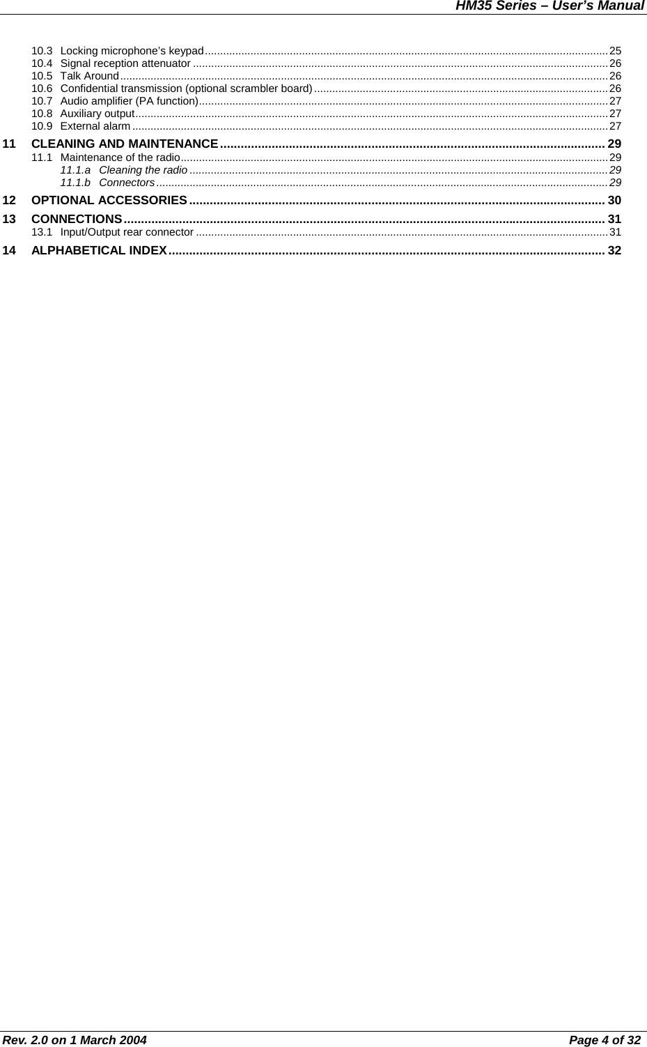
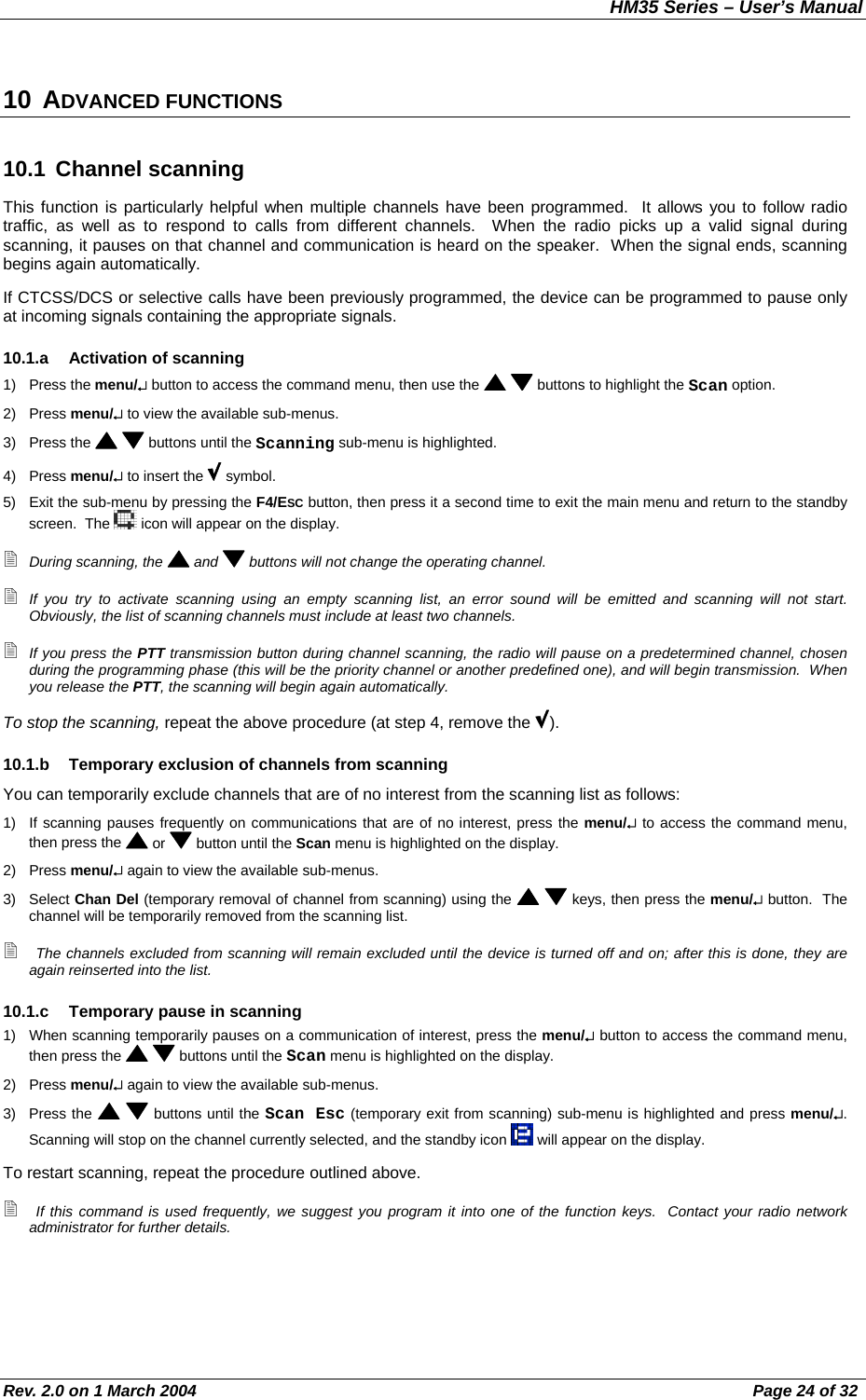
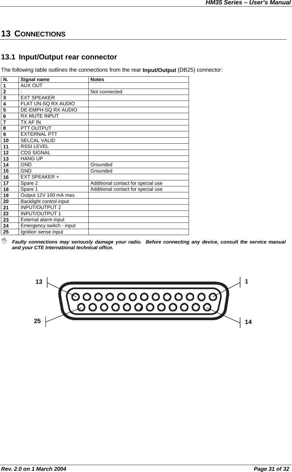
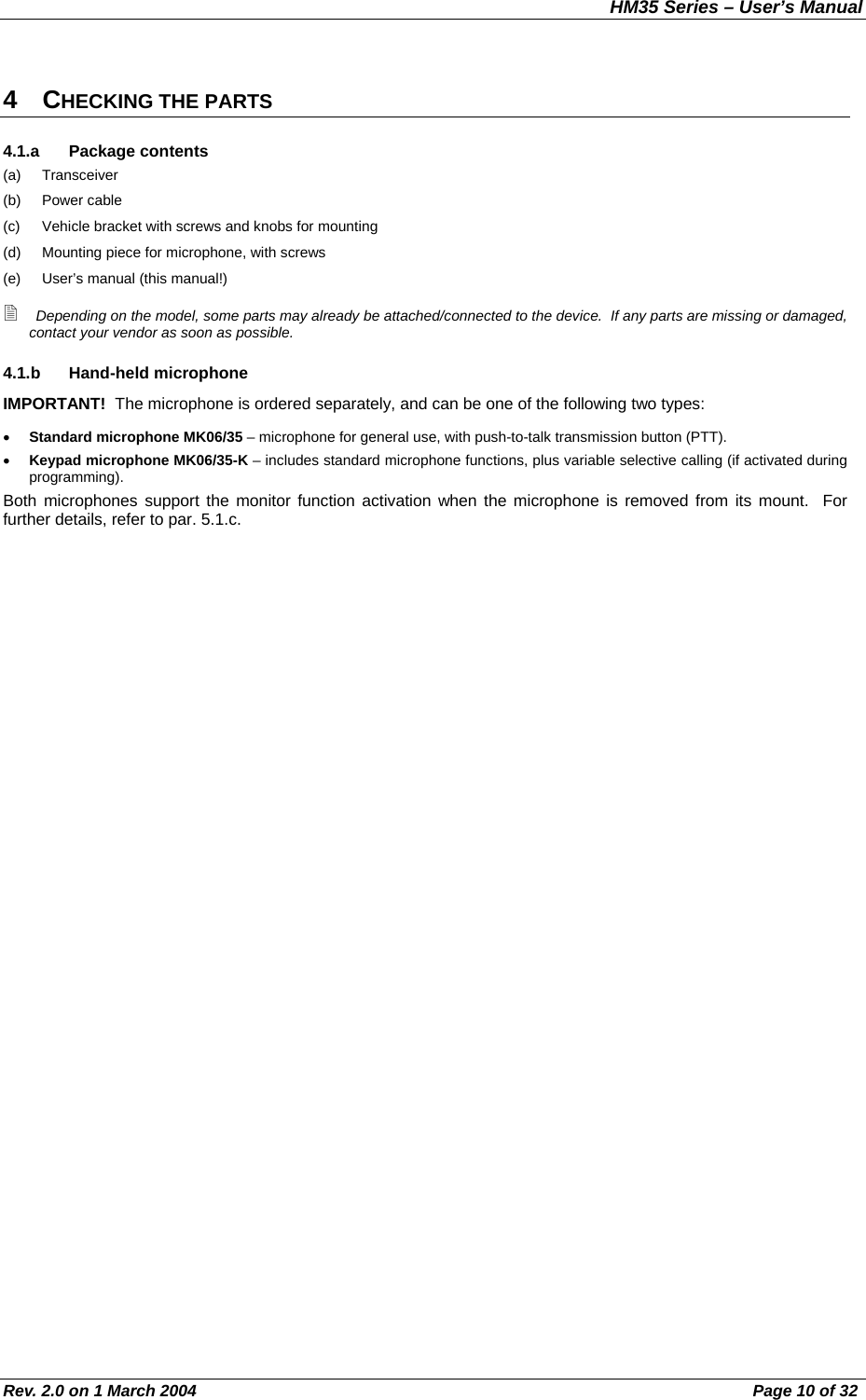
![HM35 Series – User’s Manual Rev. 2.0 on 1 March 2004 Page 8 of 32 3 PARTS OF THE RADIO AND THEIR USE 3.1 Front panel [1] Display - constantly displays the operating status of the device and guides the use of various functions through a series of icons and messages. [2] On/Off-Volume knob – used for turning the radio on/off and for adjustment of reception volume. [3] Microphone socket – this RJ type socket connects the standard hand-held (MK06/35) or keypad microphone (MK06/35-K) to the radio. [4] Programmable function keys F1, F2, F3 and F4/ESC enable the user to recall commonly used functions or can be programmed with fixed selective calls. The F4/ESC button is also used for exiting a menu (ESC). [5] (up) / (down) buttons – for channel selection and navigation of the command menu. [6] Menu/↵ button – for accessing the command menu and confirming the option shown on the display. [7] Internal speaker. [8] Status LED – is lit with different colors to indicate the radio’s status (transmission, busy channel, etc.) 3.2 Rear panel [9] Power cable – this red/black cable connects to a 13.8 VDC power source (red is positive and black is negative), for example to the vehicle battery. 9 10 11 3 7 2 651 84](https://usermanual.wiki/Midland-Radio/705445/User-Guide-502327-Page-8.png)
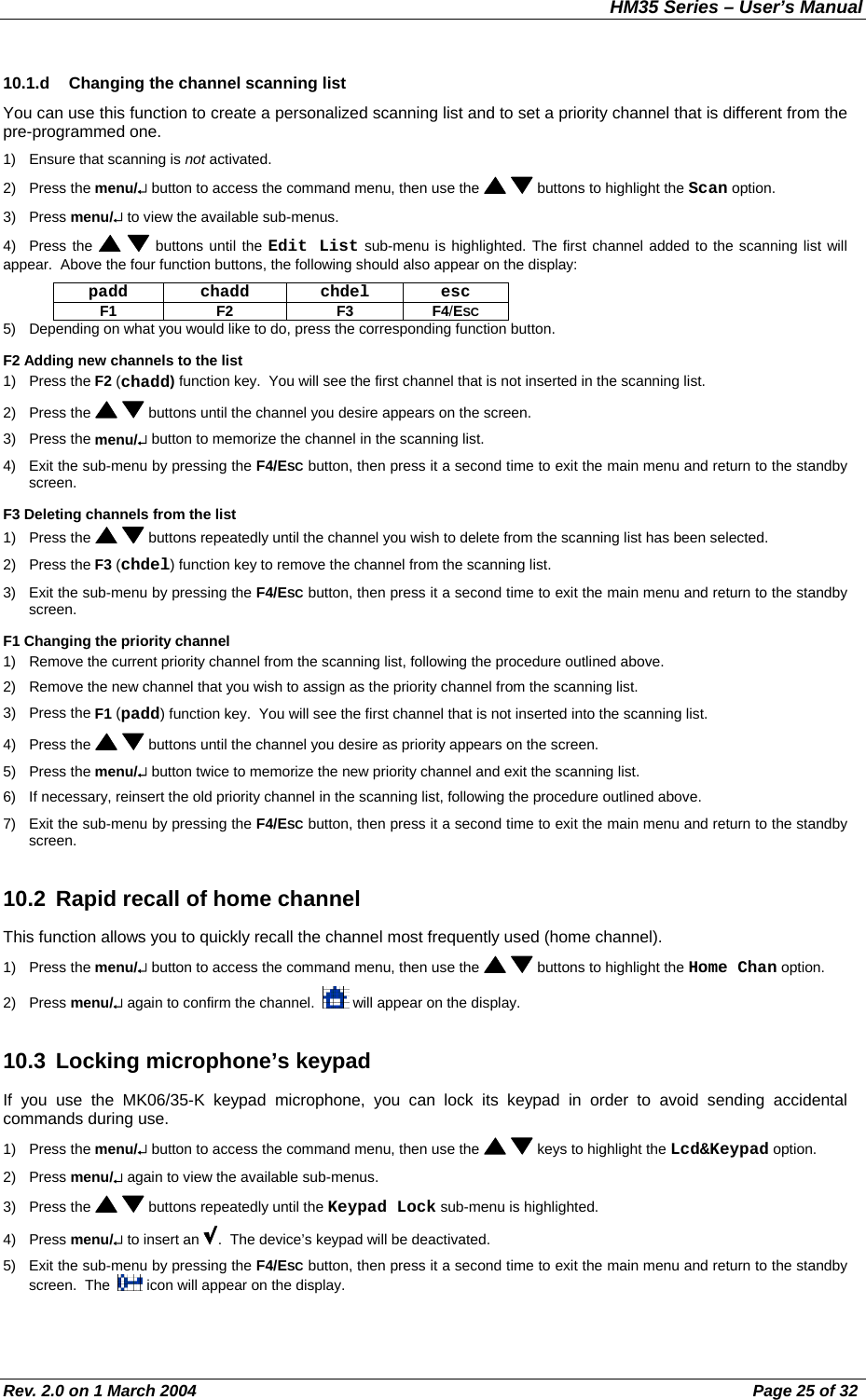
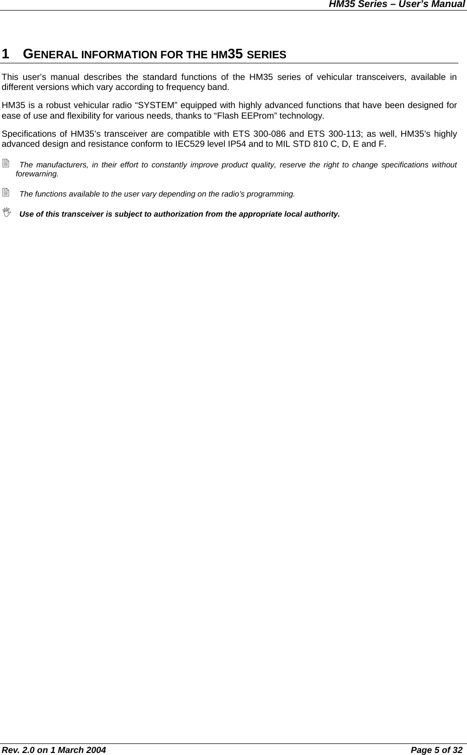
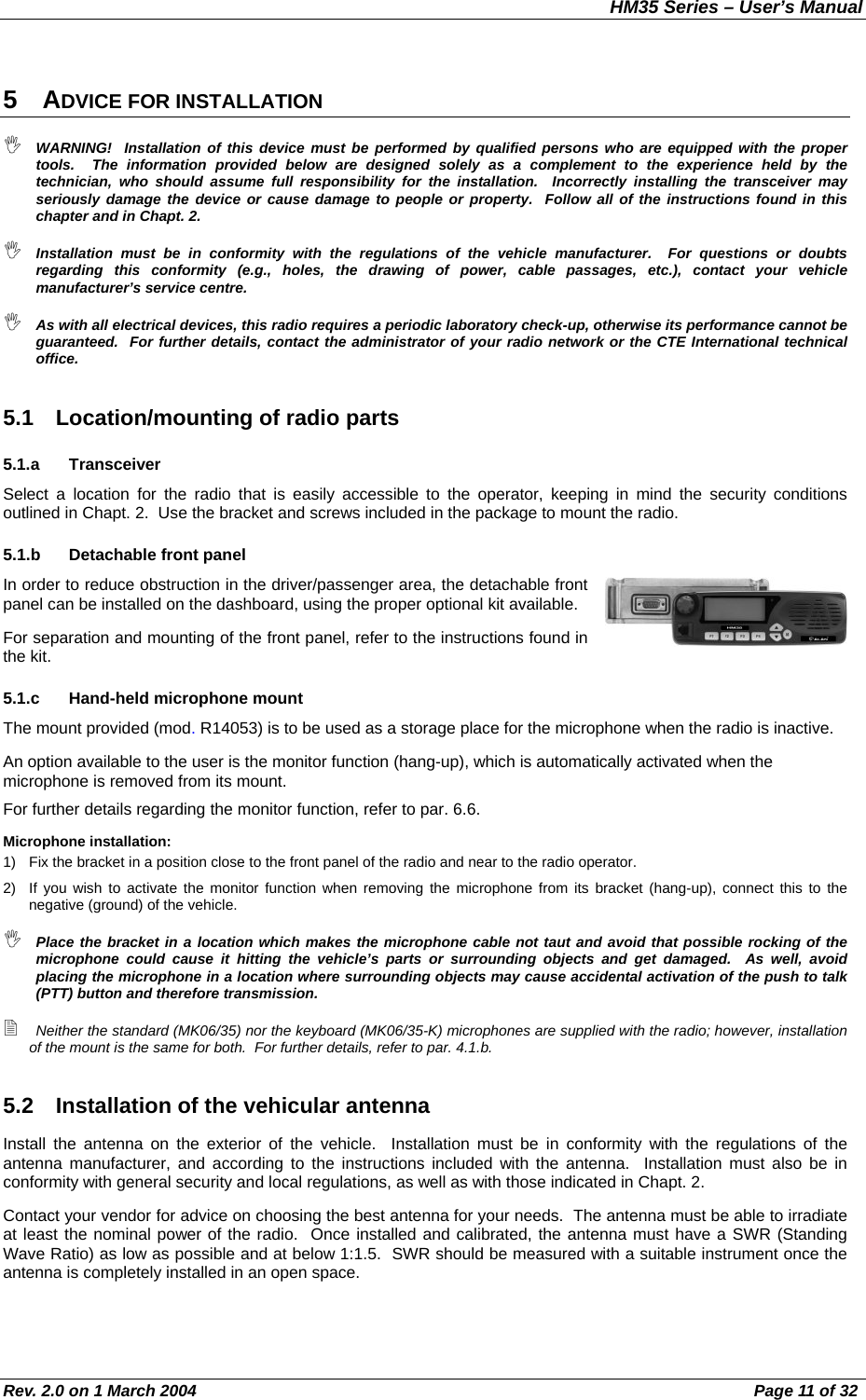
![HM35 Series – User’s Manual Rev. 2.0 on 1 March 2004 Page 9 of 32 [10] Input/output connector – for connection to the external speaker and for activation of external devices. For connections, refer to Par. 13.1. [11] Antenna socket - this SO 239 (UHF) socket is for connecting a suitable antenna. Another option is to use a BNC-type connector. For further details, please contact your local vendor.](https://usermanual.wiki/Midland-Radio/705445/User-Guide-502327-Page-9.png)
![HM35 Series – User’s Manual Rev. 2.0 on 1 March 2004 Page 12 of 32 When used in a vehicle, the radio offers optimal performance when the antenna is installed at the center of the roof, in a vertical position that is free of obstacles. 5.3 Connections A faulty connection (or connection with an unapproved device) can seriously damage the transceiver, as well as people or objects. For further details, refer to the service manual and/or to the CTE International technical office. 5.3.a Antenna After verifying the efficiency of the external antenna, connect it to the radio’s Antenna socket (refer to par. 5.2) using a suitable connector. 5.3.b Power supply Connect the red/black cable to a 13.8 VDC (+/- 10%) power source. The red terminal connects to the positive; the black is negative and must be grounded. It is important to verify that the power supply line used is able to support 10 A of continuous current. 5.3.c Connection/Disconnection of the microphone As previously mentioned, two types of microphones are available for purchase separately: • Standard microphone MK06/35 – microphone for general use, with push to talk transmission button (PTT) (not supplied). • Keypad microphone MK06/35-K – includes standard microphone functions, plus variable selective calling (if activated during programming). Standard microphone To connect the microphone, insert the microphone’s RJ plug into the [3] Microphone socket on the front panel of the radio. To disconnect the microphone, hold down the safety clip on the RJ plug and detach it from the socket with caution. Keypad microphone The keypad microphone MK06/35-K can only be used if the radio has been programmed for its activation, as per the following instructions. If it has not been programmed, the command described below will not be accessible. 1) Press the menu/↵ button to access the command menu, then press the buttons repeatedly until the Lcd&Keypad menu is highlighted. 2) Press the menu/↵ again to view the available sub-menus. 3) Press the or button repeatedly until the Keypad Micr. sub-menu is highlighted, then press menu/↵ to confirm. A will appear beside the sub-menu to indicate that the keypad microphone is active. 4) Exit the sub-menu by pressing the F4/ESC button, then press it a second time to exit the main menu and return to the standby screen. This procedure should be followed the first time you use your microphone. If you are using the standard microphone, ensure the is disabled by following the above procedure. To connect/disconnect the MK06/35-K keypad microphone, follow the same procedure as described for the standard microphone. 5.3.d External speaker (optional) If you possess an external speaker, connect it to the Input/Output [10] connector found on the rear panel of the device, referring to Chapt. 13 and to the instructions supplied with the speaker itself. The external speaker must be 8 Ohm and able to support a minimum of 12 W of power. The output of the external speaker is grounded. Be careful not to create short-circuits with the body of the vehicle. The transceiver can be programmed so the external speaker is excluded and only the internal one is used. For further details, refer to par. 8.4.](https://usermanual.wiki/Midland-Radio/705445/User-Guide-502327-Page-12.png)
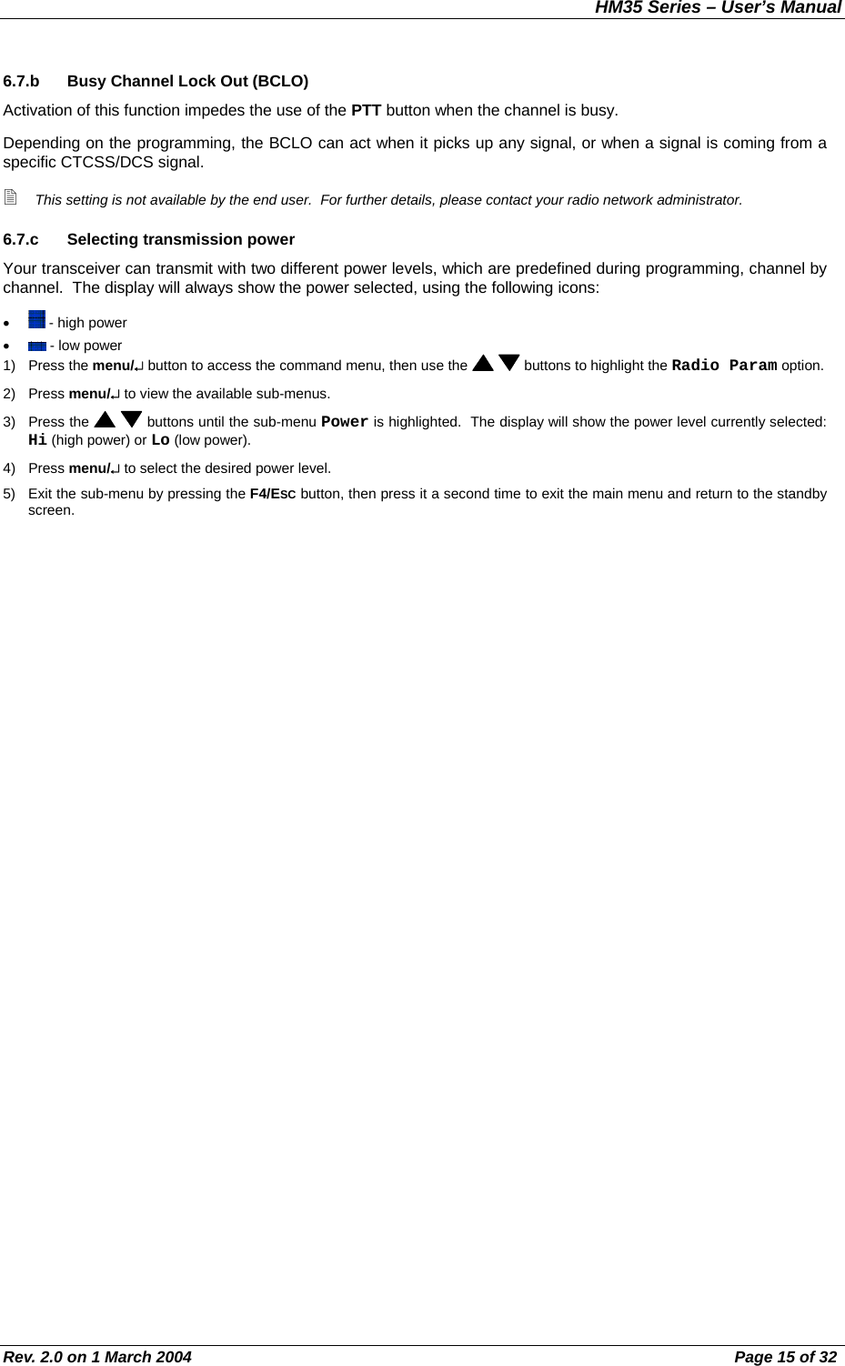
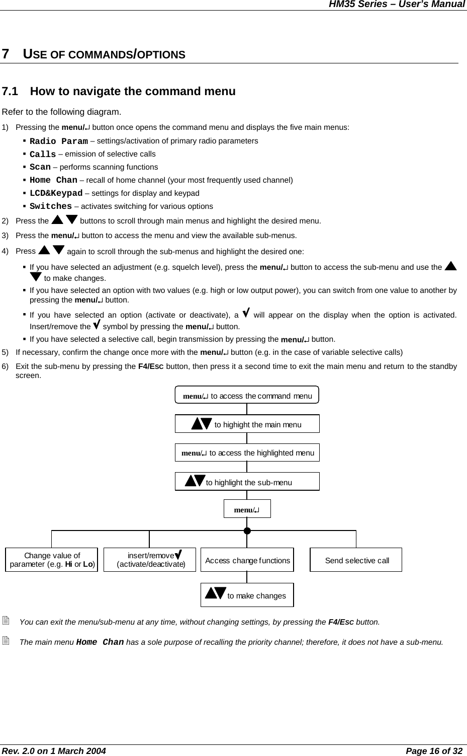
![HM35 Series – User’s Manual Rev. 2.0 on 1 March 2004 Page 14 of 32 3) Press menu/↵ to access the sub-menu. SQUELCH will appear on the display, and a horizontal bar will show the level of squelch intervention currently being used. 4) Hold down the button until the background noise is continuous. 5) Now press the button to gradually increase the level of squelch intervention, stopping as soon as the noise disappears. 6) Wait for a few seconds to ensure the noise has disappeared stably. 7) Exit the sub-menu by pressing the F4/ESC button, then press it a second time to exit the main menu and return to the standby screen. Be careful not to set the squelch level too high: you may not be able to receive weak signals. 6.6 Monitor The monitor function is mainly used for two purposes: • To allow for reception of extremely weak signals. • To temporarily disable the CTCSS/DCS and/or selective calling to allow you to listen to all communications on the tuned channel, including those outside your network. Each time the monitor function is activated, will appear on the display. 6.6.a Monitor from the menu 1) Press the menu/↵ button to access the command menu, then use the buttons to highlight Radio Param (radio parameters) from the menu. 2) Press menu/↵ to view the sub-menus available and until the Monitor sub-menu is highlighted. 3) Press menu/↵ to insert beside Monitor. This indicates that the monitor function is active. 4) Exit the sub-menu by pressing the F4/ESC button, then press it a second time to exit the main menu and return to the standby screen. 6.6.b Monitor using the microphone If the monitor function has been activated (hang-up), you will activate it each time you remove the microphone from its mount. 6.7 Transmission 1) Remove the microphone from its mount. 2) Ensure the channel is unoccupied (otherwise you will create interference), and verify the status LED is off or flashing orange. 3) Hold down the push to talk (PTT) button on the hand-held microphone. The status LED [8] to the right of the display will light up in red to confirm that you are transmitting. 4) Speak in a normal voice approximately 5 – 10cm from the microphone. 5) Release the PTT at the end of the call, ensuring the status LED is no longer lit. 6) At the end of the conversation, hang the microphone back up on its mount. Begin speaking only after having pressed the PTT button and do not release it until you have finished speaking, otherwise all or part of your message will not be transmitted. Do not yell! This does not increase the distance of transmission; rather, your words come across as distorted. Normally, a transceiver will not allow you to send and receive simultaneously, so when you are speaking, others will not be able to do so. Send your message within a reasonable time period so as not to occupy the channel for very long. Consult the following paragraphs for information on correct transmission. 6.7.a Time Out Timer (TOT) The radio can be programmed with an internal TOT (Time Out Timer), which automatically forces your radio into reception mode if you have been speaking for too long (time for this is determined in the programming phase). If this happens, release the transmission button and wait for a few seconds: the transmission functions of the radio will be automatically restored. For further information, contact your vendor or network administrator.](https://usermanual.wiki/Midland-Radio/705445/User-Guide-502327-Page-14.png)