Midland Radio 7150610D DATA RADIO User Manual USERS MANUAL
Midland Radio Corporation DATA RADIO USERS MANUAL
USERS MANUAL
OPERATOR’S MANUAL
MIDLAND MODEL 71-506-10D
FULL-DUPLEX MOBILE
Preliminary
August, 2006

71-506-10D FULL-DUPLEX MOBILE 2
SAFETY/WARNING INFORMATION
This radio is restricted to occupational use, work related operations only
where the radio operator must have the knowledge to control the exposure
conditions of its passengers and bystanders by maintaining the minimum
separation distance of 0.3 m(1 foot).
Failure to observe these restrictions will results in exceeding the FCC RF
exposure limits.
ANTENNA INSTALLATION:
The antenna must be located at least 0.3m (1 foot) away from bystanders
in order to comply with the FCC RF exposure requirements.
Important Information
All rights reserved. No part of this publication may be reproduced, transmitted,
transcribed, stored in a retrieval system, or translated into any language without the
written permission of Midland Radio Corporation
No part of any copyrighted computer programs contained in the products referred to in
this manual may be copied or reproduced without the express written consent of Midland
Radio Corporation
Midland Radio Corporation reserves the right to change the products described in this
manual without prior notice.
© Midland Radio Corporation

71-506-10D FULL-DUPLEX MOBILE 3
1.0 INTRODUCTION
Thank you for purchasing the MIDLAND MODEL 71-506-10D Full-Duplex Mobile Radio. This manual
contains information to assist you in the application and operation of the radio.
The 71-506-10D is a building block intended for use in systems requiring a compact radio for full duplex,
repeater, link, etc. The radio is capable of both analogue and digital modulation.
The 71-506-10D is designed to operate with an external, custom designed, control system, which may be
supplied by MIDLAND or by the customer. MIDLAND will provide engineering assistance and technical
information to assist in the design of the control system by the customer.
Use of the many features available in the radio will depend on the complexity of the control system.
2.0 FEATURES & PRODUCT DESCRIPTION
2.1 Standard Inclusions
The 71-506-10D transceiver is supplied complete with the following items:
71-506-10D transceiver
DC Supply Cable with Fuse and Plug
Operators Manual
Spare Fuse
Two Magnetic Keys
Mounting Plate with Hardware
2.2 Features
Designed for use with external control system
Simplex or two frequency Duplex operation
EEPROM programmable with a PC computer
Up to 64 Channels
Optional Internal Duplexer
All FM Frequency Bands from 66 to 520 MHz
Transmit Time Limiter to prevent channel
jamming
TX and RX Encryption
All-Scan and Program Scan Scanning Modes
5 Tone Encoder & Decoder plus DTMF Encoder
& Decoder
22, 26, or 35 MHz switching bandwidth (model
dependant)
Receiver front end covers full sub band without
any tuning
Channel selectable Wide or Narrow channel
spacing
Channel selectable High / Low power
CTCSS/DCS on a per channel basis
Rugged Housing
Heavy gauge mounting plate with key lock
Step-Up VCO Voltage for Superior Selectivity
Low Stand-by Current is ideal for Solar
Installations
Watch Dog Timer
2.3 Product Description
The Midland model 71-506-10D transceivers represent a great advance on the previous rugged & time
proven KG106 transceiver. They consist of separate modules all housed within one rugged, compact
mobile cabinet. The receiver, the transmitter, and the PA Unit are each enclosed within their own diecast
housings that are directly mounted to the main chassis. A full-featured logic module controls all
parameters of the radio under the control of a microprocessor. The RF Power Output is 1 - 10 Watts on a
continuous duty basis. The CTCSS module supports all EIA tones, which may be set on a per channel
basis during radio programming.
The 71-506-10D is supplied with TX and RX antenna ports to allow connection to an external duplexer or
feeder cables. Space is provided inside the housing for an antenna relay or mobile type 6-cavity duplexer.
71-506-10D FULL-DUPLEX MOBILE 4
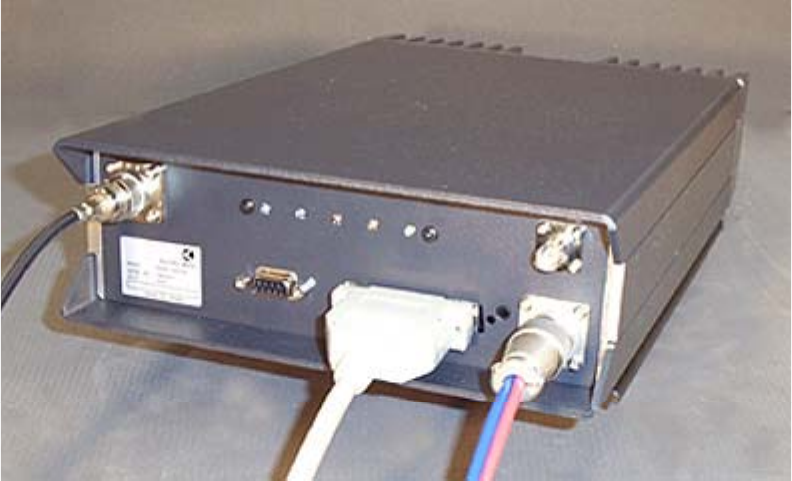
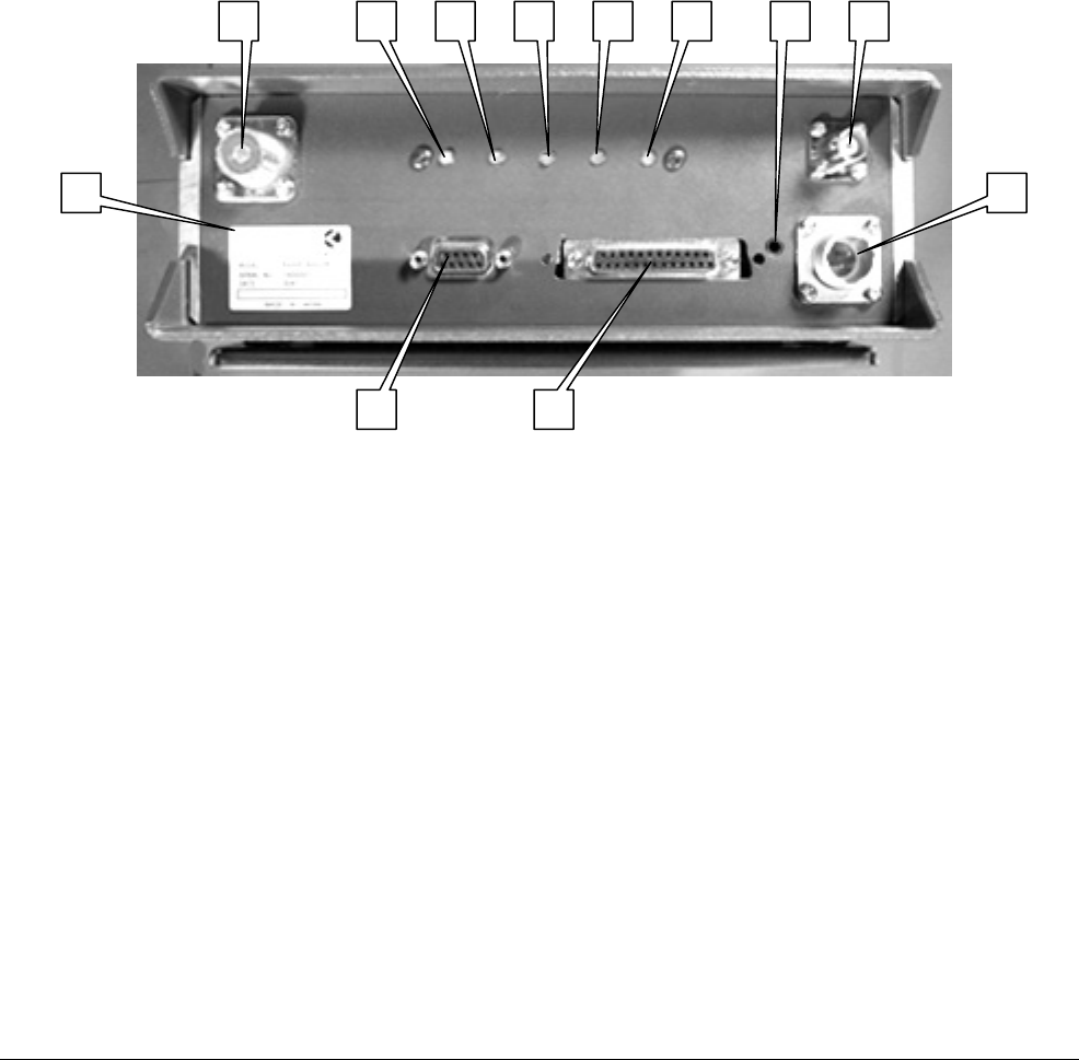
2.4 Front Panel Features
The front panel includes the following:
1. UHF Type connector for the Transmitter (optional type “N”)
2. LEDs to indicate: A=POWER, B=BUSY, C=TRANSMIT, D=ALARM, and E=REPEAT
3. Miniature jack for speaker audio output
4. BNC Connector for the Receiver
5. DC Power Connector
6. 25 position D sub connector for interface to the external control system
7. 9 position D sub connector for connection to a PC for programming
8. Model Number / FCC Label
2.5 Indicator Functions
A POWER On Indicator LED
The Power ON Indicator LED will illuminate in Green color whenever the Power ON/OFF switch is
switched to the "ON" position.
B BUSY Mode Indicator LED
The Busy Mode Indicator LED will illuminate in Green color whenever the 71-506-10D receives a
carrier signal on the selected channel that is greater then the Squelch setting.
C TRANSMIT Mode Indicator LED
The Transmit Mode Indicator LED will illuminate in Red color whenever the 71-506-10D is
transmitting.
D ALARM Mode Indicator LED
The Alarm Mode Indicator LED will illuminate (Flashing) in Amber color whenever the transceiver
detects a fault in the receiver module, the transmitter module, or the PA module on the selected
channel.
E REPEATER Mode Indicator LED
The Repeater Mode Indicator LED will illuminate in Yellow color when the selected channel has
been programmed for Repeater operation. This LED will NOT illuminate on any channel that is
programmed to operate in Base Station mode.
1 4 3
58
7 6
A B C ED

71-506-10D FULL-DUPLEX MOBILE 5
3.0 OPERATION
3.1 Installation and Programming
71-506-10D can be installed to operate Fixed Station in any mode of operation. The antenna(s)
used for this transmitter must be fixed-mounted on outdoor permanent structures. RF exposure is
addressed at the time of licensing, as required by the responsible FCC Bureau(s), including
antenna co-location requirements of §1.1307(b)(3).
The radio may also be used for mobile and transportable applications.
The 71-506-10D must be programmed before it will operate correctly. This is best done by the
equipment supplier or a competent radio engineer. They will require the correct programming kit
and a computer. Complete programming instructions are provided with the kit. If a duplexer is
used, please observe the maximum frequency range permitted by the duplexer notches.
It is important that the 71-506-10D be correctly installed at its working location. It is recommended
that this be done by a competent radio engineer.
As a minimum, it is necessary to:
• Securely attach the mounting plate to the desired location.
• Connect the DC Input power lead to a suitable 13.8 Volt Regulated DC Power supply that
has sufficient capacity. (Ensure that the DC Polarity is correct, otherwise the fuse will
blow).
• Connect the antenna feed line(s). (Check that the VSWR of the antenna is acceptable).
• Connect the Control System to the 25 position sub D connector.

71-506-10D FULL-DUPLEX MOBILE 6
3.2 Basic Operation
Note that controls and functions will vary with different control systems and with programming.
3.2.1 Switch On
Switch the 71-506-10D "ON" , the POWER indicator should illuminate.
3.2.2 Adjust the Volume Setting
Rotate the Volume Knob clockwise until the audio level from the speaker is suitable.
3.2.3 Adjust the Squelch Setting
Rotate the Squelch Knob clockwise (from the fully counter clockwise position) slowly until
the background noise can no longer be heard. It is wise to slightly rotate the knob further
in the clockwise direction so that variations in the background noise level do not "break"
the squelch setting and cause annoying noises to be heard from the speaker.
3.2.4 Select the Channel
Select the desired channel.
3.2.5 Receiving
You should now be able to hear any radio traffic that occurs on channel. It may be
necessary to further slightly adjust the Volume setting to suit your listening requirements.
3.2.6 Transmitting
Depending on the legal requirements in your country and the operating requirements
within your organization, it may be necessary to announce your Call Sign, and will
probably be necessary to announce the Call Sign of the party you are calling at the start
of your transmission.
Press the PTT switch before beginning to speak. When transmitting, it is necessary to
hold the microphone about 75mm (3") from your mouth and speak clearly into the grill of
the microphone.

71-506-10D FULL-DUPLEX MOBILE 7
4. CONTROL INTERFACE CONNECTOR DESCRIPTION
A 25 position D-sub connector for remote control is provided on the front panel of KG506.
The functions of each pin are as follows;
1 CH 0, 1 apply 1 to 6 bits of binary input to pins 1 thru 6 to select 64
2 CH 1, 2 channels, pull “LOW” for active state. Pin 1 is LSB.
3 CH 2, 4
4 CH 3, 8
5 CH 4, 16
6 CH 5, 32 MSB
7 GROUND Ground
8 RSSI Receive Signal Strength Indication, 0 to 5 V DC
9 DISC. OUT Discriminator audio output, low level
10 SQ. CONT. To external Squelch control, 10K pot to ground
11 BUSY Goes to 5V logic high when squelch is opened by signal
12 MUTE When pulled low, mutes RX and Repeat audio
13 MOD-1 Microphone modulation input
14 GROUND Ground
15 PTT Pull low to transmit
16 MOD-2 Digital modulation input, TTL level, DC sensitive
17 SIMPLEX Provides logic output during simplex operation
18 ERROR Provides “flashing” high/low if error/alarm is present
19 DECODE Logic low upon decoding 5-tone or DTMF code
20 RX AUD-1 With pin 21, provides balanced “0 dBm” audio
21 RX AUD-2 With pin 20, provides balanced “0 dBm” audio
22 TX OUT Indicates error in PA, low power or high SWR
23 EXT. POW SW Connect to ground through external POWER switch
24 VOLUME To external volume control, 10 K pot to ground
25 +12V (nom) Switched 13.6 VDC to external accessories
CN1 Mini phone jack Balanced Speaker output both sides above ground.

71-506-10D FULL-DUPLEX MOBILE 8
6. SPECIFICATIONS
6.1 General
Frequency Range
Version SA 300 - 335MHz
Version A 335 - 370MHz
Version B 365 - 400MHz
Version C 400 - 435MHz
Version DS 420 - 455MHz
Version D 440 - 475MHz
Version E 465 - 500MHz
Version F 485 - 520MHz
Number of Channels 64 channels (observe duplexer limitations)
Channel Spacing 12.5/20/25/30KHz
Operation Mode Semi Duplex/Full Duplex
Antenna Impedance 50 ohm unbalanced
Power Supply DC 13.6V negative ground only (external)
Consumption 8 amperes or less
Environmental Conditions -30 to +60 degree C, 95% humidity @35C
Dimensions 220 (w) 82 (h) 347 (d) mm
Weight 6 kgs.
6.2 Transmitter
Output Power 10W continuous, 13W maximum
Switchable Bandwidth Full sub-band
Frequency Deviation 5KHz(wide band) 2.5KHz(narrow band)
Frequency Stability +/- 1KHz
Frequency Response Within +1, -3dB, 300-3000Hz @1KHz ref.
Signal to Noise Ratio 50dB or more @1KHz 70% mod. (45dB at narrow)
Modulation Distortion 3% or less
Spurious & Harmonics 0.25uW or less
6.3 Receiver
Switchable Bandwidth full sub-band
IF Frequencies 1st IF 73.35MHz, 2nd IF 455KHz
Frequency Stability +/- 1KHz
Sensitivity 0.4uV or less for 20dB N.Q. / 0.3uV for 12dB SINAD
Squelch Sensitivity 0.25uV or less
Selectivity 70dB or more at 25KHz
Blocking 90dB or more
Intermodulation 70dB or more
Spurious Response 70dB or more
AF Response Within +1, -3dB, 300-3000Hz @1KHz ref.
AF Distortion 5% or less @1KHz 70% mod
Signal to Noise Ratio 50dB or more @1KHz 70% mod. (45dB at narrow)