Midland Radio 75440 2 W UHF Radio User Manual 70 440BP User s Manual
Midland Radio Corporation 2 W UHF Radio 70 440BP User s Manual
UserManual.wiki
>
Midland Radio
>
75440 User Manual
>
revised manual
Contents
1.
8
2.
revised manual
revised manual
Navigation menu
Upload a User Manual
Namespaces
Wiki Guide
HTML
PDF
Info
Views
User Manual
Discussion / Help
Navigation
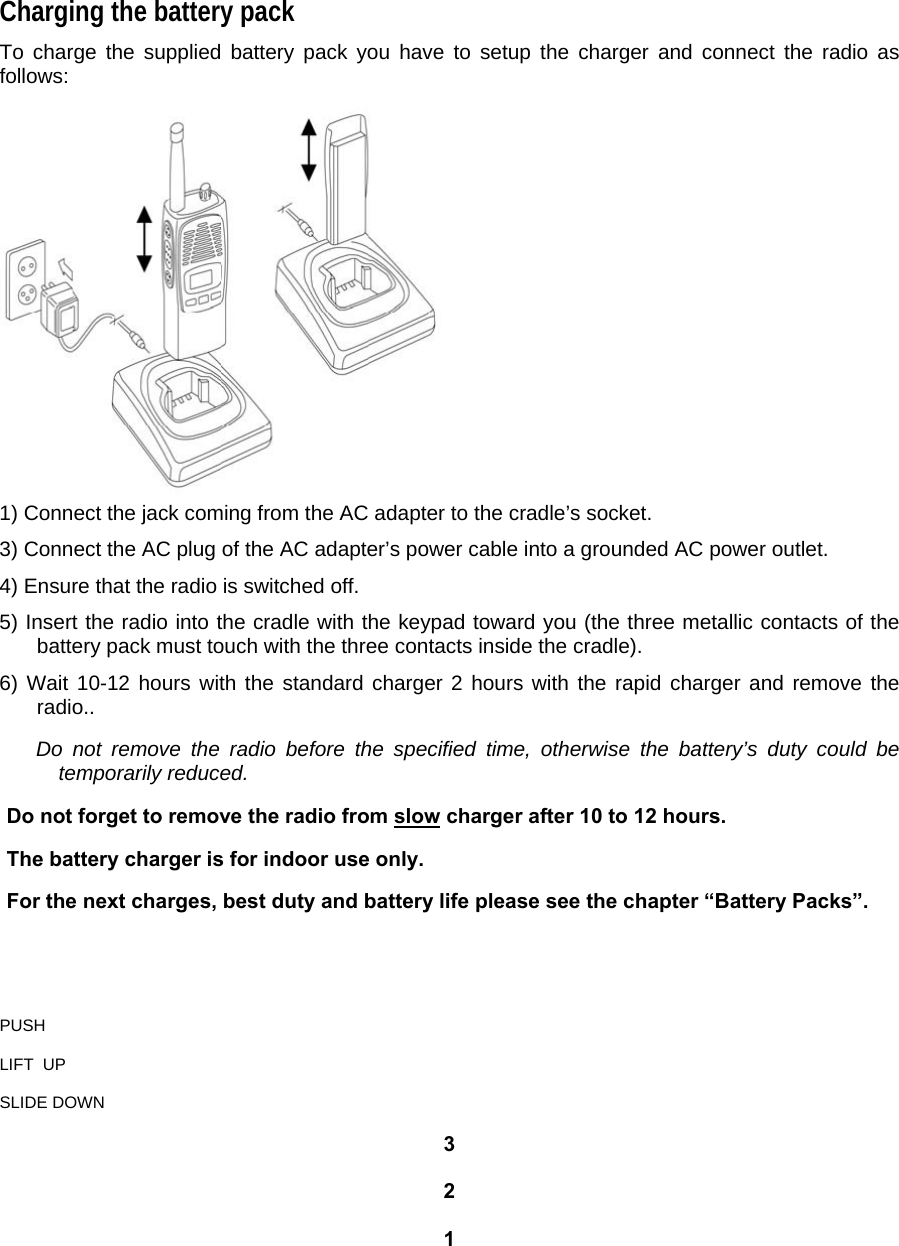
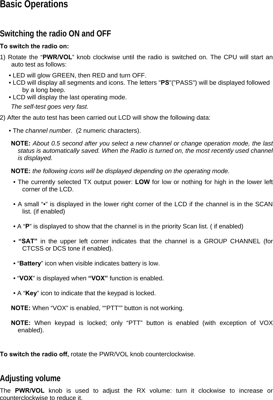
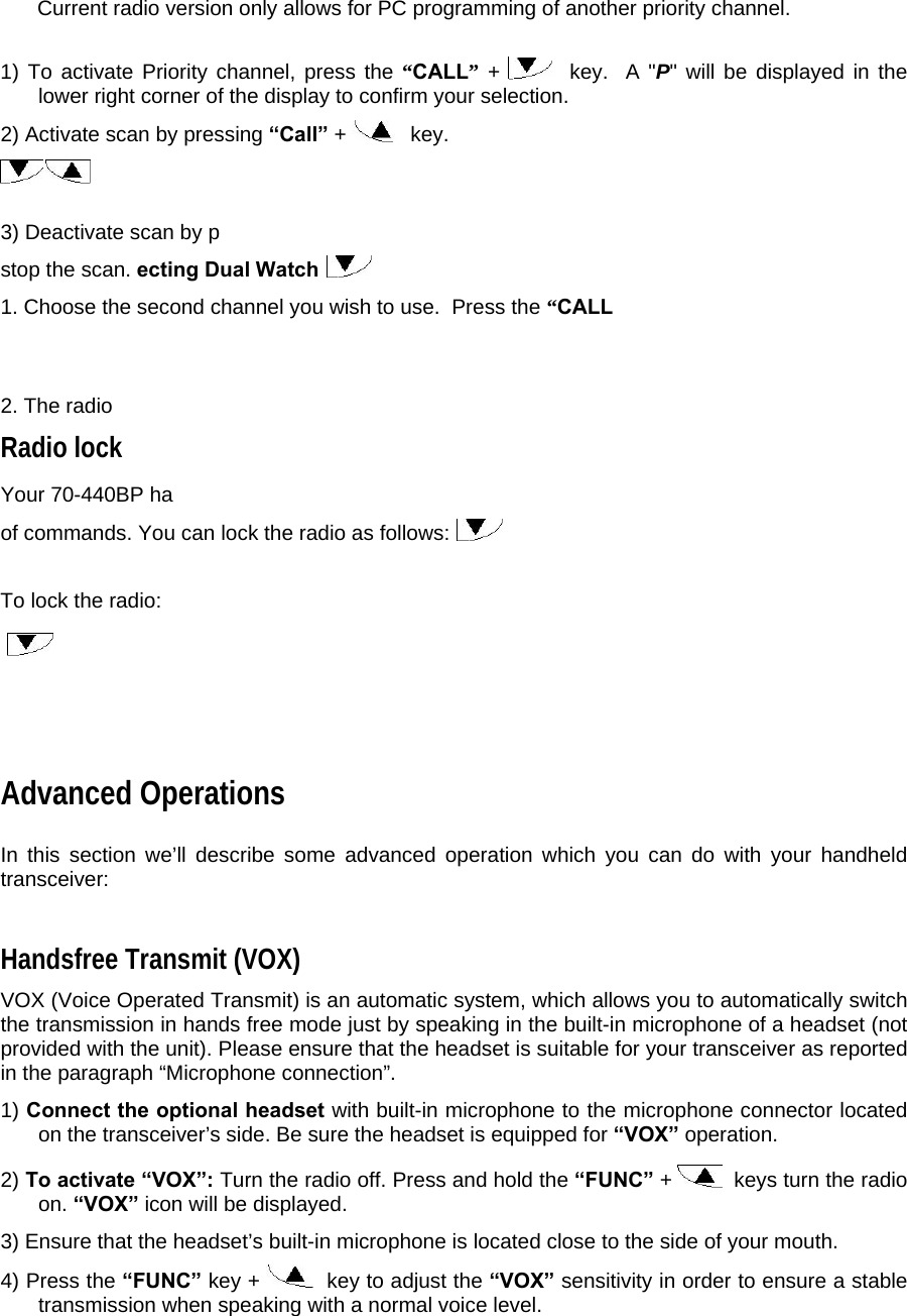
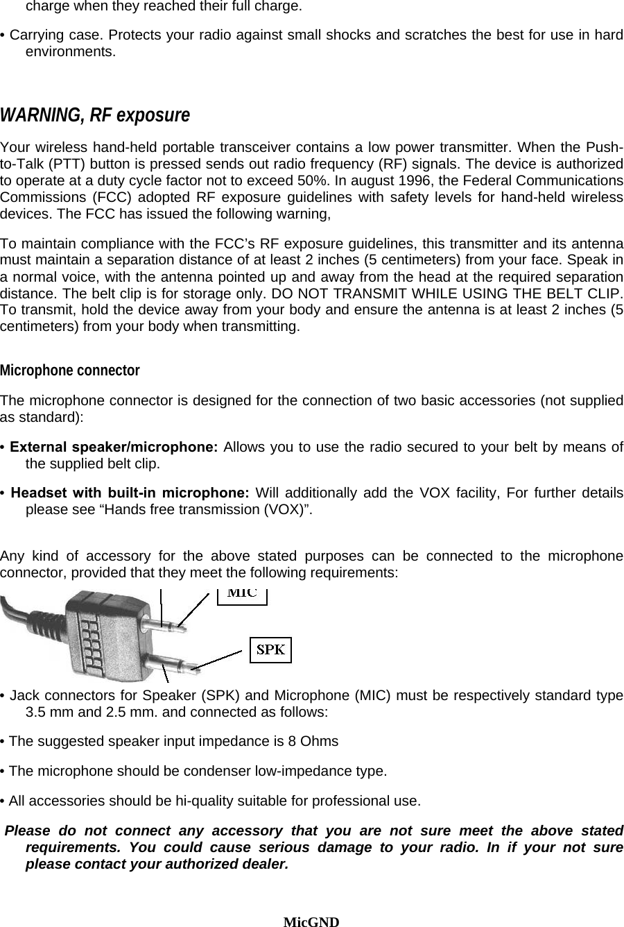
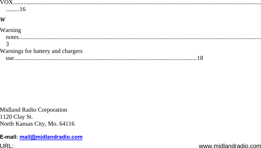
![Key names will be highlighted in bold. Important sentences and words are highlighted in Italic. Part Names and their functions Please have a look at the following parts description in order to familiarize yourself with the transceiver’s main parts and controls. Numbers in brackets refer to the illustration. Top [1] Antenna connector. Fit the antenna to this connector (MX thread type). [2] Power ON/OFF knob. Rotate this knob to turn the transceiver on and off. [3] Status LED. Glows in different colors to show the radio’s current status. Front](https://usermanual.wiki/Midland-Radio/75440.revised-manual/User-Guide-560202-Page-5.png)
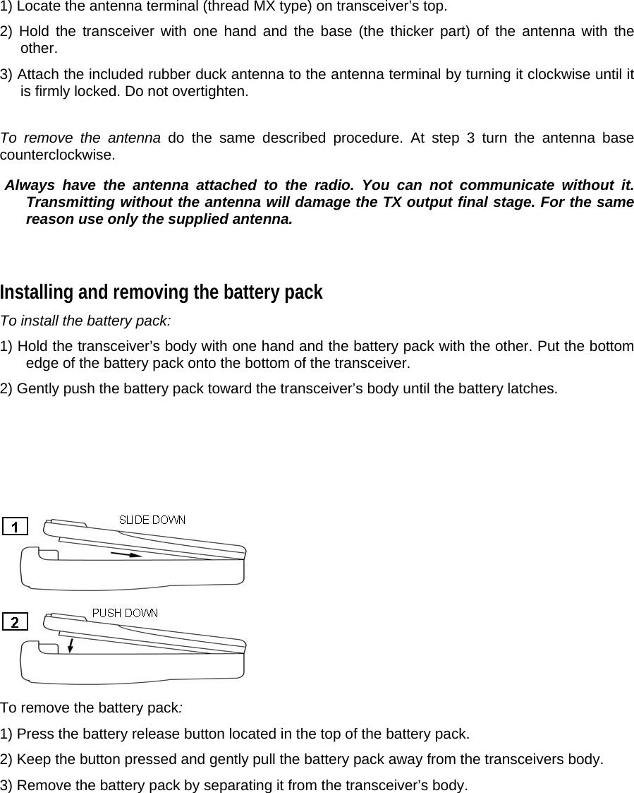
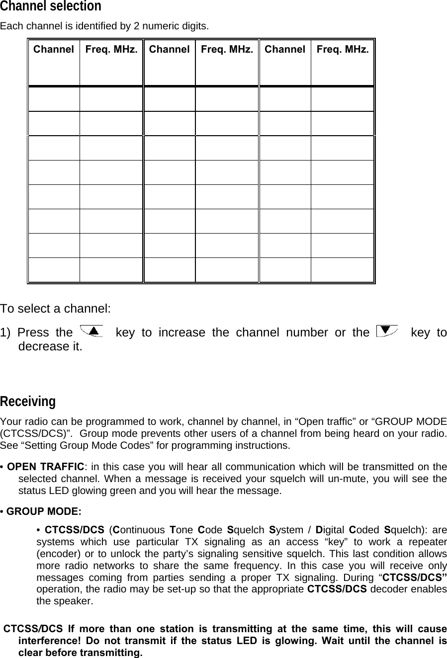
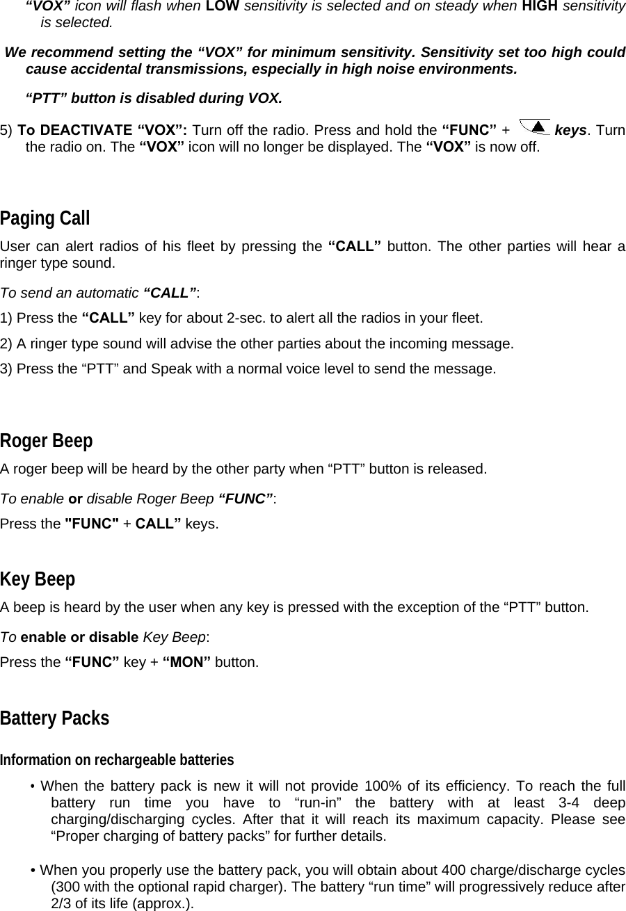
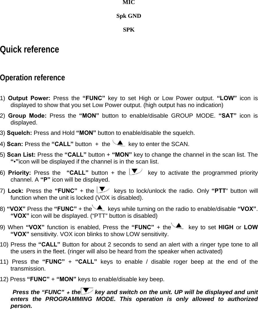
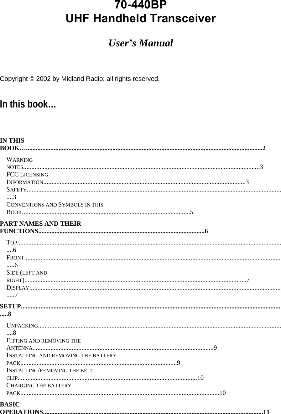
![[4] Speaker. The built in speaker located in this point emits the received sound. [5] LCD display. Shows the radio’s parameters (channel number etc.). Icon and symbols are further explained in the paragraph “Display”. Whenever any key or button is pressed, the display is automatically backlit for few seconds. [6] (Up) and (down) buttons. For scrolling forward and backward through the channel list and for changing function values. [7] “FUNC” button. Allows changing function values. [8] Microphone. Your voice is detected by the microphone located in this place 1 5 4 8 7 6 3 2](https://usermanual.wiki/Midland-Radio/75440.revised-manual/User-Guide-560202-Page-6.png)
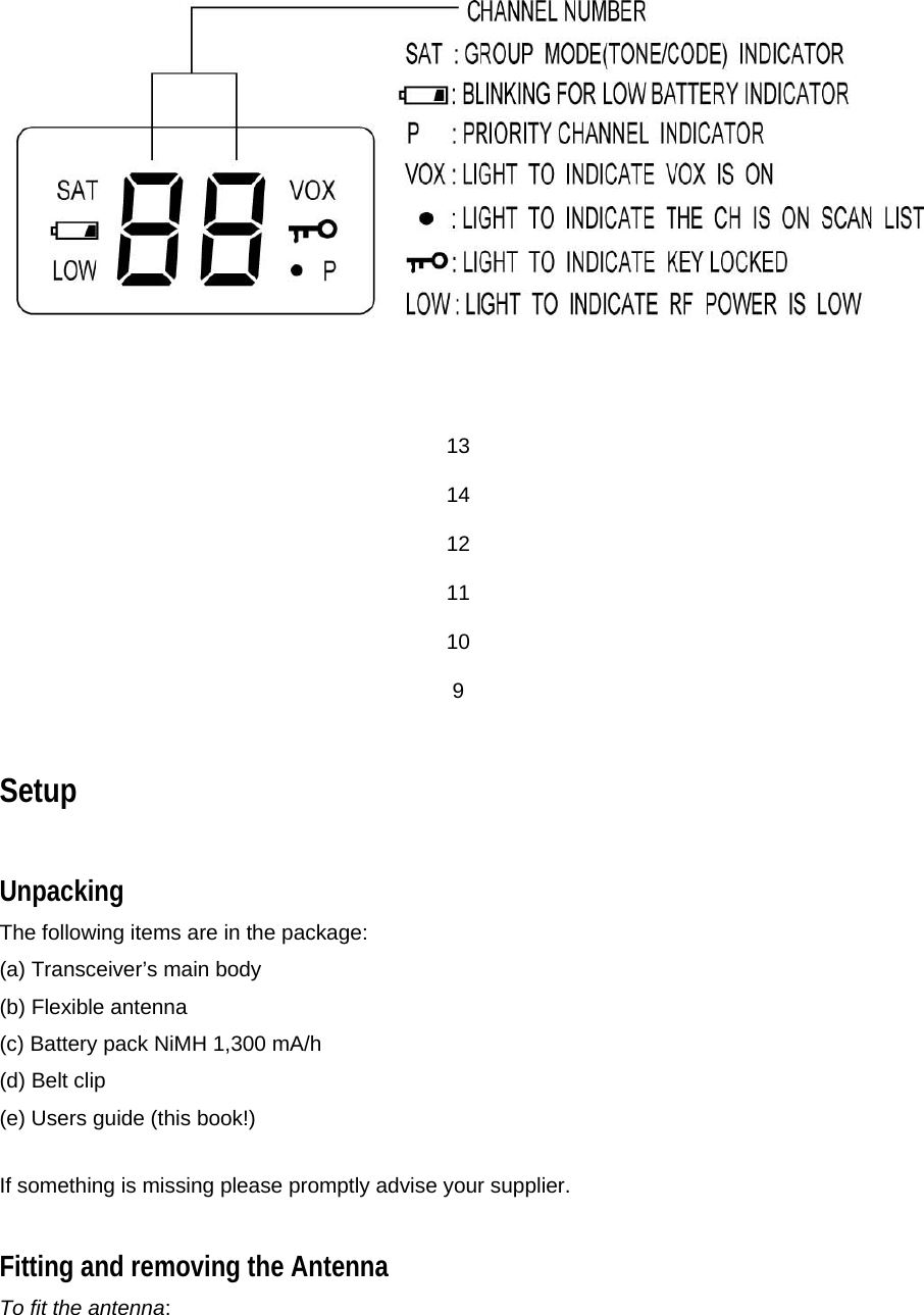
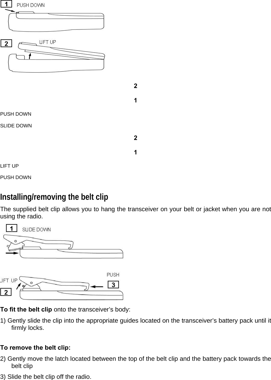
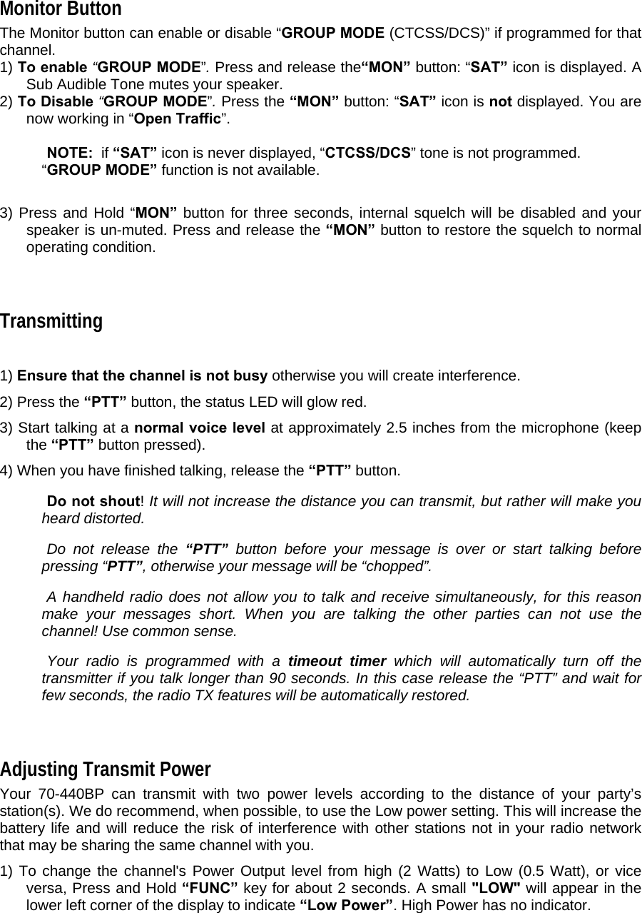
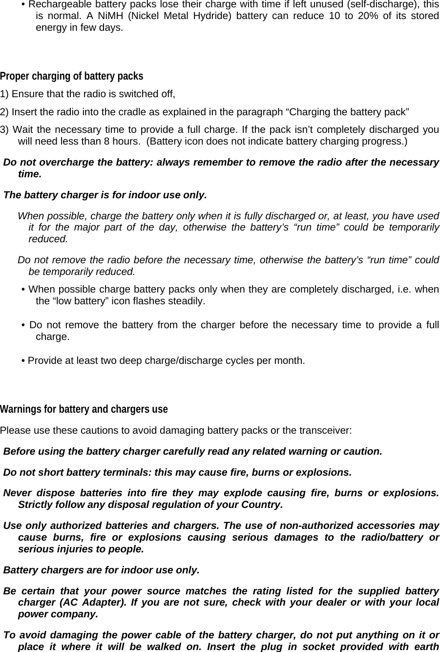
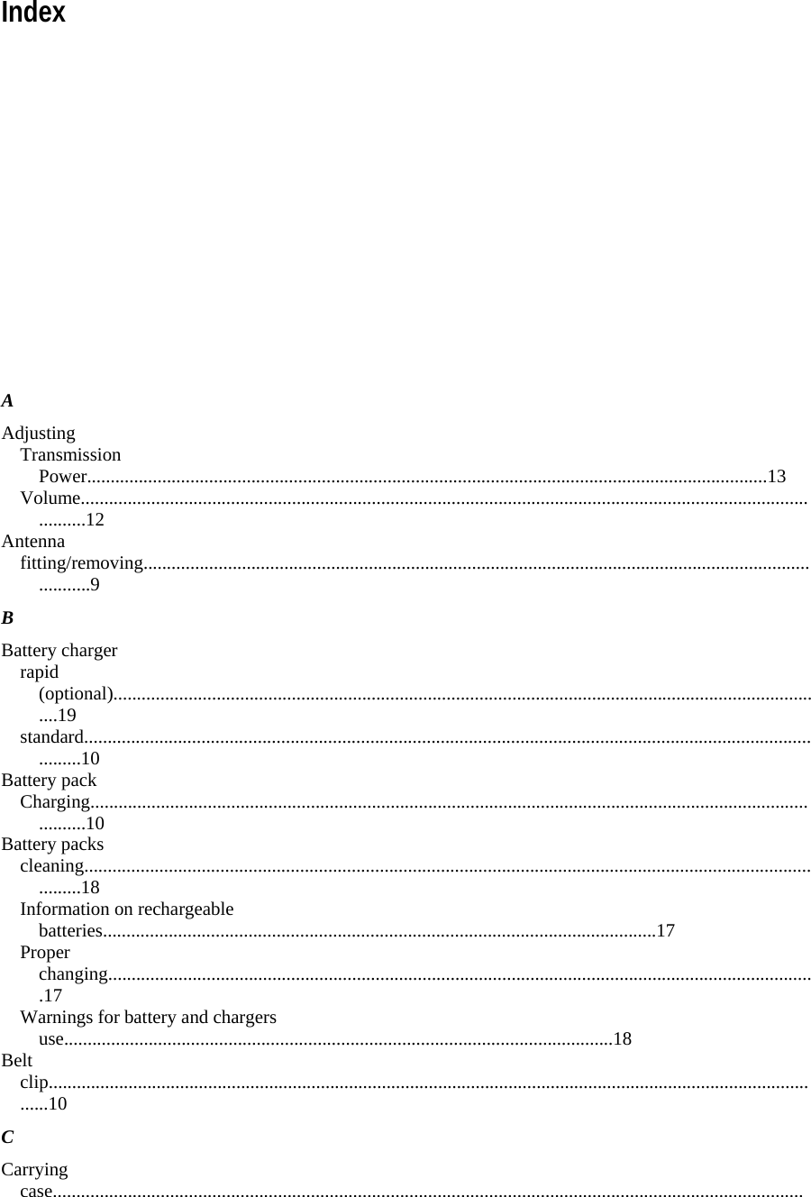
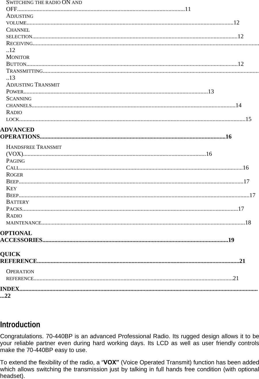
![Side (left and right) [9] Microphone connector. For remote speaker/microphone, headsets for VOX use and other accessories. It must be protected with the supplied plastic cap when not in use. For the related pin connections please see to “Microphone connection”. [10] Battery pack. This NiMH battery pack supplies energy to your radio. [11] Release button (located on the battery’s body). Allows to remove the battery pack [12] MON (monitor) button. Enables the loudspeaker for monitoring of the tuned channel when CTCSS/DCS is enabled. [13] “CALL” button. Sends a paging “CALL” (if enabled) [14] “PTT” (Push To Talk) button. When pressed switches the transceiver from receive to transmit. Display This section explains the meaning of the various indications that may appear on the LCD of your 70-440BP handheld transceiver:](https://usermanual.wiki/Midland-Radio/75440.revised-manual/User-Guide-560202-Page-7.png)