Midland Radio 90105 PORTABLE TRANSCEIVER User Manual USERS MANUAL
Midland Radio Corporation PORTABLE TRANSCEIVER USERS MANUAL
USERS MANUAL

7610-4700-1201
Issue A
4700
APCO25 CONVENTIONAL
HANDHELD RADIO
OPERATING MANUAL
© ASELSAN Inc. 3 November 2006
The continuous improvement of its products is the intent of ASELSAN, who reserves the right to make design changes
without notice.
All rights reserved. reproduction of issue to third parties in any form whatever is not permitted without written permission
from the proprietors.
PO. Box 101 Yenimahalle, Ankara 06172 TURKEY
Tel: +90 312 5921000 * Fax: +90312 3541946
http://www.aselsan.com.tr
lojistik_destek@aselsan.com.tr
4700 APCO25 CONVENTİONAL HANDHELD RADIO
OPERATING MANUAL
7610-4700-1201
Issue A
DEVICE SHOULD BE OPENED BY AUTHORIZED PERSONEL. OTHERWISE IT WILL
BE OUT OF WARRANTY.
BEFORE GETTING START TO USE THE DEVICE READ USER MANUALS.
4700 APCO25 Conventional Handheld Radio is produced by ASELSAN A.Ş.
Usage period of device is 10 year.
It is packed and labeled according to commercial packaging standards.

4700 APCO25 CONVENTİONAL HANDHELD RADIO
OPERATING MANUAL
7610-4700-1201
Issue A

4700 APCO25 CONVENTİONAL HANDHELD RADIO
OPERATING MANUAL
7610-4700-1201
Issue A
ATTENTION!
If device is stored more than 3 months, crypto key may be erased because of the
discharge of the chargeable battery of the crypto board and "EMERGENCY ERASE
BATTERY DISCHARGED" appears at the display. In this case device must be
connected to an accumulator/battery/power supply and wait for at least 30 minutes
at position ON. And then crypto loading process must be repeated.

4700 APCO25 CONVENTİONAL HANDHELD RADIO
OPERATING MANUAL
7610-4700-1201
Issue A
INTENTIALLY LEFT BLANK.

4700 APCO25 CONVENTİONAL HANDHELD RADIO
OPERATING MANUAL
7610-4700-1201
Issue A
CONTENTS
1 GENERAL INFORMATION................................................................................................................... 1-1
1.1 GENERAL PROPERTIES............................................................................................................. 1-1
1.2 TECHNICAL PROPERTIES.......................................................................................................... 1-3
1.3 PACKAGE CONTENT .................................................................................................................. 1-4
1.3.1 “ASELSAN 4700 Series Handheld Radio” Box ........................................................................ 1-4
1.3.2 “4451 Desktop Charger” Package ............................................................................................ 1-7
1.3.3 “Desktop Charger Adapter” Package ....................................................................................... 1-7
2 PHYSICAL PROPERTIES AND USAGE.............................................................................................. 2-1
2.1 FRONT PANEL ............................................................................................................................. 2-1
2.1.1 LCD Display.............................................................................................................................. 2-2
2.1.2 Key Pad .................................................................................................................................... 2-5
2.2 SIDE PANEL ................................................................................................................................. 2-8
2.2.1 PTT Button................................................................................................................................ 2-8
2.2.2 Mode and Power Change Button.............................................................................................. 2-8
2.2.3 Option / Monitor Button............................................................................................................. 2-8
2.3 TOP PANEL .................................................................................................................................. 2-9
2.3.1 Emergency Call Button ............................................................................................................. 2-9
2.3.2 Antenna Connector................................................................................................................... 2-9
2.3.3 Channel Switch......................................................................................................................... 2-9
2.3.4 Turn On/Off- Volume Switch................................................................................................... 2-10
2.3.5 Option Connector.................................................................................................................... 2-10
2.3.6 Transceiver LED ..................................................................................................................... 2-10
2.4 ALERT TONES AND CALL ALERTS ......................................................................................... 2-10
2.5 LIGHTING ALERTS .................................................................................................................... 2-10
2.6 WRITTEN ALERTS..................................................................................................................... 2-11
2.7 MENU SCREENS ....................................................................................................................... 2-13
3 MENU USSAGE.................................................................................................................................... 3-1
3.1 SETTINGS MENU......................................................................................................................... 3-1
3.2 CALL LOG MENU ......................................................................................................................... 3-3
3.3 SMS MENU................................................................................................................................... 3-3
3.4 PROGRAMMED MESSAGE MENU ............................................................................................. 3-3
3.5 STATUS MENU ............................................................................................................................ 3-4
3.6 RADIO INFO MENU...................................................................................................................... 3-4
3.7 SCAN MENU................................................................................................................................. 3-5
3.8 CRYPTO MENU............................................................................................................................ 3-6
4 OPERATING INFORMATION............................................................................................................... 4-1
4.1 RADIOS' MODES.......................................................................................................................... 4-1
4.1.1 Analog Mode............................................................................................................................. 4-1
4.1.2 Digital Mode.............................................................................................................................. 4-1
4.2 RADIO'S OPERATING MODES ................................................................................................... 4-2
4.2.1 System Mode............................................................................................................................ 4-2
4.2.2 Direct Mode............................................................................................................................... 4-2
5 HOW TO USE........................................................................................................................................ 5-1
5.1 REMOVING AND ATTACHING OF THE BATTERY BLOCK....................................................... 5-1
5.2 MAINTENANCE ............................................................................................................................ 5-4
6 SERVED SERVICES TO THE RADIO USERS .................................................................................... 6-1
6.1 EMERGENCY CALL ..................................................................................................................... 6-1
6.2 GROUP CALL ............................................................................................................................... 6-1

4700 APCO25 CONVENTİONAL HANDHELD RADIO
OPERATING MANUAL
7610-4700-1201
Issue A
6.3 GENERAL CALL ........................................................................................................................... 6-1
6.4 INDIVIDUAL CALL ........................................................................................................................ 6-1
6.5 CALL ALERT................................................................................................................................. 6-1
6.6 PHONE CALL ............................................................................................................................... 6-2
6.7 PRESENT STATUS ...................................................................................................................... 6-2
6.8 SEND STATUS ............................................................................................................................. 6-2
6.9 STATUS REQUEST...................................................................................................................... 6-2
6.10 SHORT MESSAGE (SMS)............................................................................................................ 6-2
6.11 PROGRAMMED MESSAGE......................................................................................................... 6-3
6.12 DATA SERVICES ......................................................................................................................... 6-3
6.13 ANALOG CALL ............................................................................................................................. 6-3
6.14 SELECTIVE CALL ........................................................................................................................ 6-3
6.15 TONED CALL................................................................................................................................ 6-4
6.16 REGISTERING ............................................................................................................................. 6-4
6.17 CALLER IDENT ............................................................................................................................ 6-4
6.18 REPEAT CALL.............................................................................................................................. 6-4
6.19 CHANNEL MODE ACCESS ......................................................................................................... 6-4
6.20 CHANNEL SCAN .......................................................................................................................... 6-5
6.21 GROUP SCANNING ..................................................................................................................... 6-5
6.22 SHORT CUT ................................................................................................................................. 6-5
6.23 AUDIBLE ALERTS........................................................................................................................ 6-5
6.24 LIGHTING ALERTS ...................................................................................................................... 6-5
6.25 TRANSMISSION TIME OUT......................................................................................................... 6-6
6.26 BUSY CHANNEL LOCK ...............................................................................................................6-6
6.27 DTMF ............................................................................................................................................ 6-6
6.28 SELECTING CHANNEL................................................................................................................ 6-6
6.29 KEYLOCK ..................................................................................................................................... 6-6
6.30 SIGNAL LEVEL............................................................................................................................. 6-6
6.31 BATTERY CHARGE LEVEL......................................................................................................... 6-6
7 SIDE UNITS........................................................................................................................................... 7-1
7.1 ANTENNAS................................................................................................................................... 7-1
7.2 BATTERY BLOCKS...................................................................................................................... 7-1
7.3 BATTERY BLOCK CLIPSES ........................................................................................................ 7-2
7.4 CHARGER .................................................................................................................................... 7-2
7.5 CIK UNIT....................................................................................................................................... 7-4
7.6 ACCESSORIES ............................................................................................................................ 7-5
7.6.1 Handheld Microphone Set ........................................................................................................ 7-5
7.6.2 Inner Helmet Microphone-Earlap Set ....................................................................................... 7-6
7.6.3 Tube security Packet ................................................................................................................ 7-6
7.6.4 VIP Ring Microphone/PTT-Earlap Set...................................................................................... 7-7
7.6.5 Tube Throat Microphone-Earlap Set ........................................................................................ 7-7
7.6.6 Tactical Helmet Set................................................................................................................... 7-7

4700 APCO25 CONVENTİONAL HANDHELD RADIO
OPERATING MANUAL
7610-4700-1201
Issue A
FIGURES
Figure 1-1: ASELSAN 4700 APCO25 Conventional Handheld Radio Front View......................................... 1-1
Figure 1-2: Handheld Radio Packing First Appearance................................................................................. 1-5
Figure 1-3: Handheld Radio Packing Second Appearance............................................................................1-6
Figure 1-4: Handheld Radio Package Content............................................................................................... 1-6
Figure 1-5: “4451 Desktop Charger” Appearance with package and without package.................................. 1-7
Figure 1-6: Desktop Charger Adapter Appearance with package.................................................................. 1-7
Figure 1-7: Desktop Charger Adapter Appearance without package ............................................................ 1-8
Figure 2-1: ASELSAN 4700 APCO25 Conventional Handheld Radio Front View......................................... 2-1
Figure 2-2: LCD Display Appearance............................................................................................................. 2-2
Figure 2-3: Icons at Radio Display ................................................................................................................. 2-2
Figure 2-4: Display Layout at Digital Mode .................................................................................................... 2-4
Figure 2-5: Display Layout at Analog Mode ................................................................................................... 2-4
Figure 2-6: ASELSAN 4700 APCO25 Conventional Handheld Radio Keypad.............................................. 2-5
Figure 3-1: ASELSAN Logo............................................................................................................................ 3-2
Figure 7-1: CIK Unit........................................................................................................................................ 7-4
Figure 7-2: Handheld Radio CIK Socket ........................................................................................................ 7-4
TABLES
Table 1-1: ASELSAN 4700 APCO25 Conventional Handheld Radio General Properties............................. 1-3
Table 1-2: ASELSAN 4700 APCO25 Conventional Handheld Radio Receiver Properties ........................... 1-4
Table 1-3: ASELSAN 4700 APCO25 Conventional Handheld Radio Transmitter Properties ....................... 1-4
Table 1-4: “ASELSAN 4700 Series Handheld Radio” Package Contents ..................................................... 1-4
Table 2-1: Other Icons.................................................................................................................................... 2-3
Table 2-2: Alphanumerical Key Definitions at Editor Displays of Menu ......................................................... 2-7
Table 2-3: Alert Tones and Call Alerts ......................................................................................................... 2-10
Table 2-4: Written Warnings......................................................................................................................... 2-11
Table 7-1: Desktop Charger LED Warnings................................................................................................... 7-3

4700 APCO25 CONVENTİONAL HANDHELD RADIO
OPERATING MANUAL
7610-4700-1201
Issue A
INTENTIALLY LEFT BLANK.
4700 APCO25 CONVENTİONAL HANDHELD RADIO
OPERATING MANUAL
7610-4700-1201
Issue A 1-1
1 GENERAL INFORMATION
1.1 GENERAL PROPERTIES
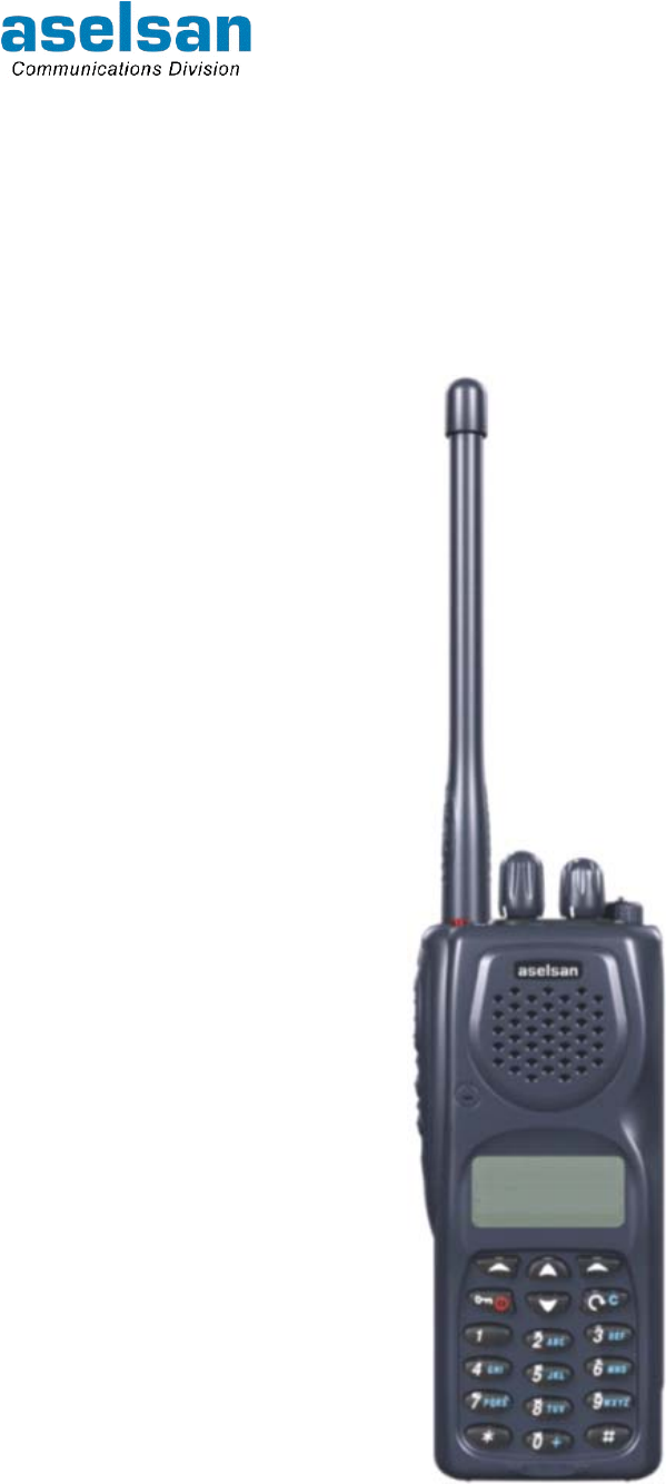
ASELSAN 4700 APCO25 Conventional Handheld Radio Front view is given in Figure 1-1.
Figure 1-1: ASELSAN 4700 APCO25 Conventional Handheld Radio Front View

4700 APCO25 CONVENTİONAL HANDHELD RADIO
OPERATING MANUAL
7610-4700-1201
Issue A 1-2
ASELSAN 4700 APCO25 Conventional Handheld Radio is developed according to the
following criteria:
• Synthesized structure,
• Microprocessor controlled structure,
• Surface mount technology usage,
• Loading external program by FLASH EPROM,
• PC controlled full automatic test and adjustment,
• Easy maintenance,
• Hardware crypto option board,
• LCD display (with 3 colors) and keypad,
• High level and high quality audio output,
• Giving information to user by audible, lighting and printed warnings,
• User interface for easy use,
• DTMF support,
• Various type of accessories,
• Full-band operating at VHF and UHF bands,
• Compatible with TGM ST-001 standards,
• Compatible with TIA/EIA-603-A standard at Analog Mode,
• Compatible with TIA/EIA-102-CAAB standard at Digital Mode,
• Compatible with APCO25 EIA/ TIA 102 standards,
• Compatible with MIL-STD-810E procedures.

4700 APCO25 CONVENTİONAL HANDHELD RADIO
OPERATING MANUAL
7610-4700-1201
Issue A 1-3
1.2 TECHNICAL PROPERTIES
Table 1-1: ASELSAN 4700 APCO25 Conventional Handheld Radio General Properties
General Technical Properties
Frequency Band 146-174MHz, 406-470MHz
Operating Frequency Band Width 28MHz (VHF) / 64MHz (UHF)
Channel Spacing (Digital) 12.5kHz
Channel Spacing (Analog) 25kHz
Channel Number 300
RF Output Power 1-5W ± %10
Modulation (Analog) 11F3 (12.5kHz) / 16F3 (25kHz)
Modulation (Digital) C4FM
RF Rate (Digital) 4.8ks/s
Data Rate (Digital) 7.2kb/s (clear) 9.6kb/s (protected)
Audio Encoder IMBE (4.4kb/s)
RF Input/Output Impedance 50Ω
Microphone Input Impedance 2kΩ
Operating Way Simplex or half-duplex
Operating Voltage 7.2VDC (Handheld radio),
Operating Current maximum <1.7A (Tx), <0.20A (Rx)
Standby Current maximum <10mA
Operating Temperature Range -30°C ∼ +60°C
Operating Voltage Range Standard supply voltage ±%20
Storage Temperature Range -40°C ∼ +85°C
Environmental Condition Standard MIL-STD-810-E
Storage ETS 300 019 Class 1.2
Shipping ETS 300 019 Class 2.3
Usage ETS 300 019 Class 7.3
Humidity (EIA/TIA RS-316C) 95% Relative Humidity at 50°C
Dimensions maximum (Y/G/D) 147/ 58.5/ 39mm ±%2 (with Li Ion 900mAh battery block, without
antenna)
Weight maximum 0.4kg (with Li Ion 1800mAh battery block)
Battery Life (with 1000mAh battery and
5W output power) minimum 8 hours
4700 APCO25 CONVENTİONAL HANDHELD RADIO
OPERATING MANUAL
7610-4700-1201
Issue A 1-4
Table 1-2: ASELSAN 4700 APCO25 Conventional Handheld Radio Receiver Properties
Receiver Technical Properties
Broadcasted Unwanted Broadcast ≤100µV/m @ f ≥30MHz
Reference Sensitivity ≤-119dBm
Unwanted Receiving Suppression ≥75dB
Inter-modulation Suppression ≥70dB
Signal Shift Band Width ≥1000Hz
Audio Frequency Output Distortion <5% @ 500mW / 8Ω
Table 1-3: ASELSAN 4700 APCO25 Conventional Handheld Radio Transmitter Properties
Transmitter Technical Properties
Operating Frequency certainty ≤0.5ppm
Broadcasted Unwanted Broadcast ≥75dB
Transmitted Unwanted Broadcast ≥75dB
C4FM Transmission Current
<850mA @ 1W
<1150mA @ 2W
<1500mA @ 4W
<1700mA @ 5W
1.3 PACKAGE CONTENT
ASELSAN 4700 APCO25 Conventional Handheld Radio is delivered in three different
packages:
1. “ASELSAN 4700 Series Handheld Radio” Package
2. “4451 Desktop Charger” Package
3. “Desktop Charger Adapter” Package
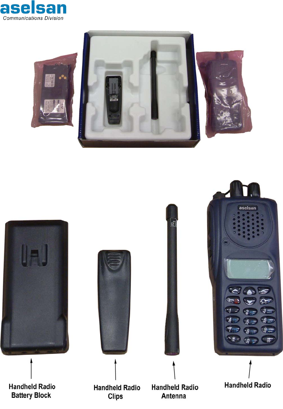
1.3.1 “ASELSAN 4700 Series Handheld Radio” Box
This box contains handheld radio and basic components. Content of the box is listed at
Table 1-4 and shown at Figure 1-4.
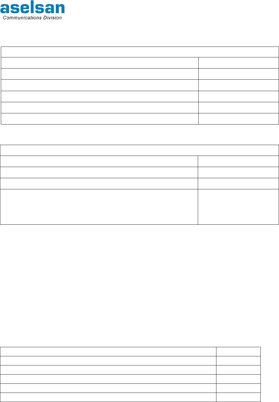
Table 1-4: “ASELSAN 4700 Series Handheld Radio” Package Contents
Item Qty (EA)
ASELSAN 4700 APCO25 Conventional Handheld Radio 1
Handheld Radio Battery Block 1
Handheld Radio Clips 1
Handheld Radio Antenna 1
Handheld Radio User Manual 1
4700 APCO25 CONVENTİONAL HANDHELD RADIO
OPERATING MANUAL
7610-4700-1201
Issue A 1-5
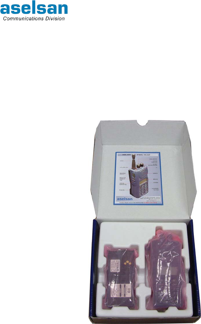
When the package has opened first appearance of the package is as given in Figure 1-2.
Battery block is at the left size, handheld radio is at the right side. If these pieces are
removed from their places clips is take place under battery block and antenna take place
under the handheld radio as shown in Figure 1-3.
Items are covered with ergonomic plastic packaging materials.
Except the items given in Table 1-4 "4700 APCO25 Conventional Handheld Radio
Operating Manual" (the one you are reading at the moment) can also take place in this
package according to the contract. One Operating Manual is given for each radio.
Figure 1-2: Handheld Radio Packing First Appearance
4700 APCO25 CONVENTİONAL HANDHELD RADIO
OPERATING MANUAL
7610-4700-1201
Issue A 1-6
Figure 1-3: Handheld Radio Packing Second Appearance
Figure 1-4: Handheld Radio Package Content
4700 APCO25 CONVENTİONAL HANDHELD RADIO
OPERATING MANUAL
7610-4700-1201
Issue A 1-7
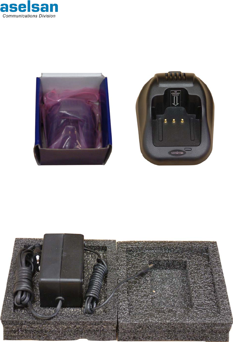
1.3.2 “4451 Desktop Charger” Package
4451 Desktop charger consist of two pieces; the charger and the adapter. Charger itself is
take place in this package. Package content and appearance of the device is given in
Figure 1-5.
Figure 1-5: “4451 Desktop Charger” Appearance with package and without package
1.3.3 “Desktop Charger Adapter” Package
Desktop charger adapter is replaced to its package inside protective foam. Appearance of
the package is given in Figure 1-6.
Figure 1-6: Desktop Charger Adapter Appearance with package
4700 APCO25 CONVENTİONAL HANDHELD RADIO
OPERATING MANUAL
7610-4700-1201
Issue A 1-8
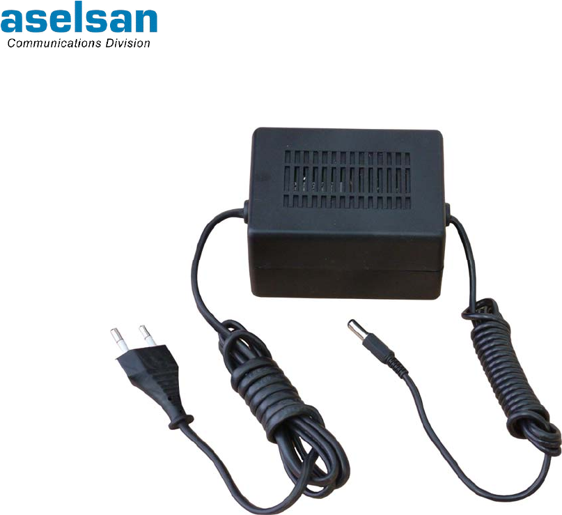
The appearance of the charger adapter without package is given in Figure 1-7.
Figure 1-7: Desktop Charger Adapter Appearance without package
4700 APCO25 CONVENTİONAL HANDHELD RADIO
OPERATING MANUAL
7610-4700-1201
Issue A 2-1
2 PHYSICAL PROPERTIES AND USAGE
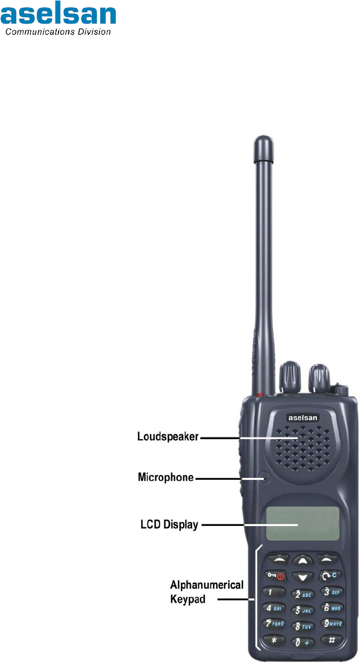
2.1 FRONT PANEL
Figure 2-1: ASELSAN 4700 APCO25 Conventional Handheld Radio Front View
Loudspeaker, microphone, LCD display and alphanumerical keypad take place at the front
panel of 4700 APCO25 Conventional Handheld Radio.
4700 APCO25 CONVENTİONAL HANDHELD RADIO
OPERATING MANUAL
7610-4700-1201
Issue A 2-2
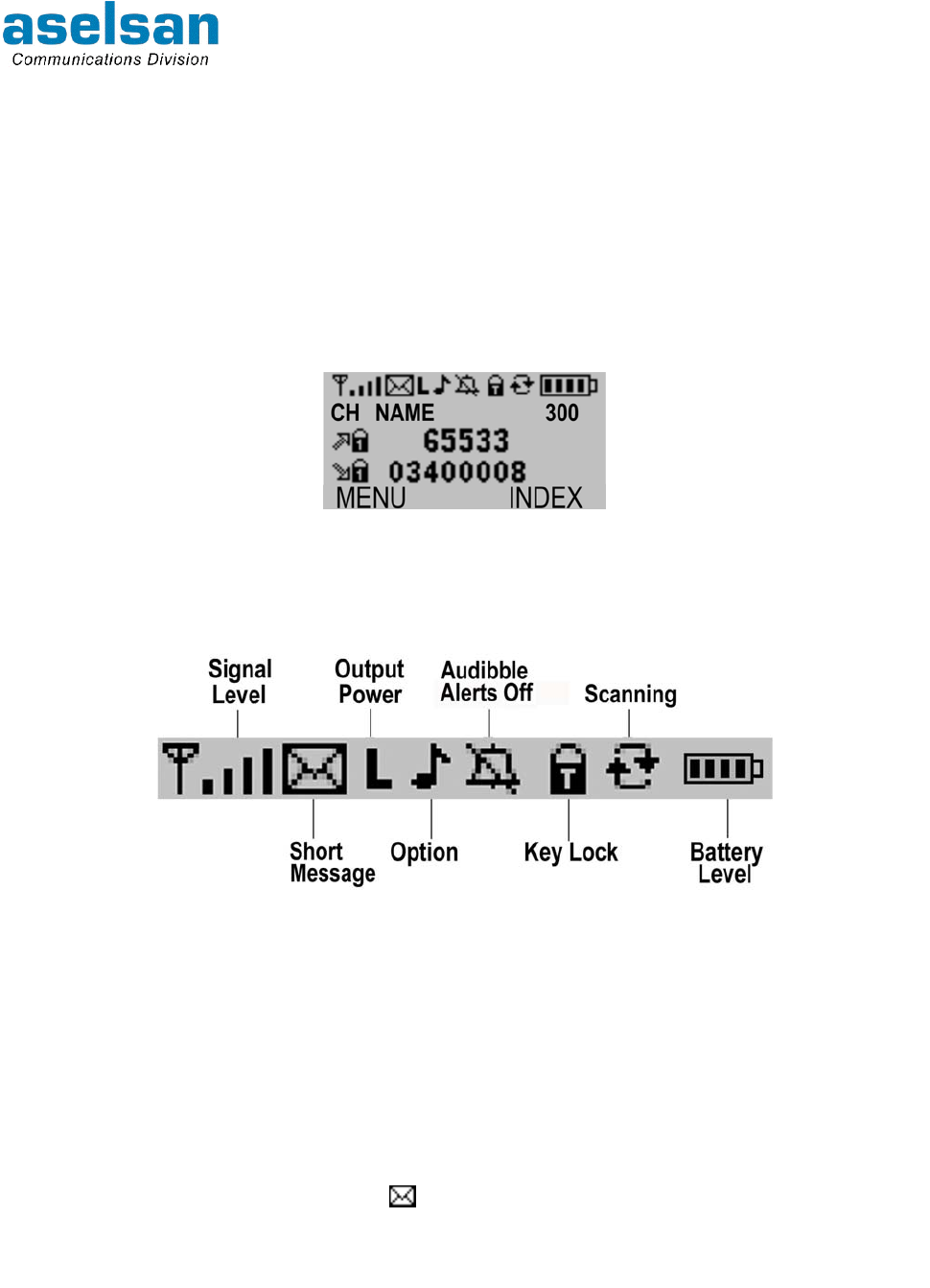
2.1.1 LCD Display
Layout of the display is adjusted as; Icons at the top of the display, 3 rows between top
and button and software buttons at the button. Software buttons cannot be seen at the
display except strolling between menus, site name or received/started call type is
appeared instead. Menu index option cannot be seen at the display until pressing a key.
LCD Display appearance is given in Figure 2-2.
Icons do not appear at the display during strolling between menus. First row of the 5 rows
indicates the software button, one row indicates the next menu, one row indicates the
previous menu and two rows indicate the existing menu.
Figure 2-2: LCD Display Appearance
2.1.1.1 Icons and Functions
Meanings of the icons at the radio's display are given below:
Figure 2-3: Icons at Radio Display
2.1.1.1.1 Signal Level Icon
Received signal is shown as 4 levels. Antenna symbol is always seen at the display as
long as the radio has got the service. As the receiving signal gets stronger, bars at the
display appears in order from short to long. Read value for RSSI is given under INFO
Menu.
2.1.1.1.2 Short Message (SMS) Icon
When a short message has received icon illuminates at the display. It goes on lighting
unless all the messages are opened.
2.1.1.1.3 Output Power Icon
L appears at Low Power, M appears at Middle Power and H icon appears at High Power.
4700 APCO25 CONVENTİONAL HANDHELD RADIO
OPERATING MANUAL
7610-4700-1201
Issue A 2-3
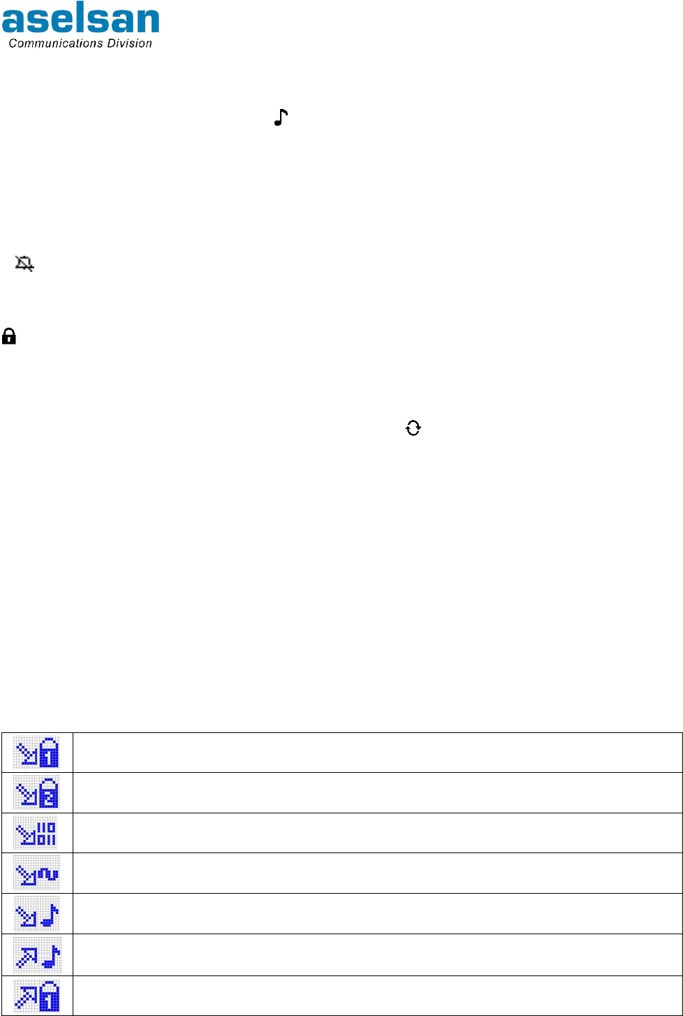
2.1.1.1.4 Option Icon
When the recognize option is in use icon appears at the display.
Analog Mode: Icon appears if tone code squelch and selective call functions are in use.
Digital Mode: If one of channel monitor properties is programmed to radio icon does not
light, if it is not programmed icon lights at the display.
2.1.1.1.5 Audible Alerts off Icon
If icon appears at the display it means that Audible Alerts are off.
2.1.1.1.6 Keys Locked Icon
icon indicates that the front panel keys, which are called as keypad, are locked. When
the keypad is functional icon does not appear.
2.1.1.1.7 Scanning Icon
When the scanning has been started at direct mode icon appears at the display. Icon
disappears when the scanning mode is exited. Broadcast received channel name and
number appears at the display during scanning. "SCANNING" blinks at the lowest row.
2.1.1.1.8 Battery Level
Remaining battery capacity is shown with 5 leveled icon. When the battery is nearly
discharge icon blinks at the display. During charge and discharge if radio is on icon bars
are lights in order to indicate charging information. When the battery is fully charged icon
appears normal at the display.
2.1.1.2 Other Icons
Icons that appear at the display about received and transmitted signal mode and their
meanings are explained in Table 2-1.
Table 2-1: Other Icons
Appears when a digital "Secret" cryption broadcast is received at digital mode.
Appears when a digital "Private" cryption broadcast is received at digital mode.
Appears when a digital clear broadcast is received at digital mode.
Appears when an analog broadcast is received.
Appears when a toned broadcast is received at analog mode.
Appears when the radio makes a toned call at analog mode.
Appears when the radio makes a digital "Secret" crypted broadcast at digital mode.
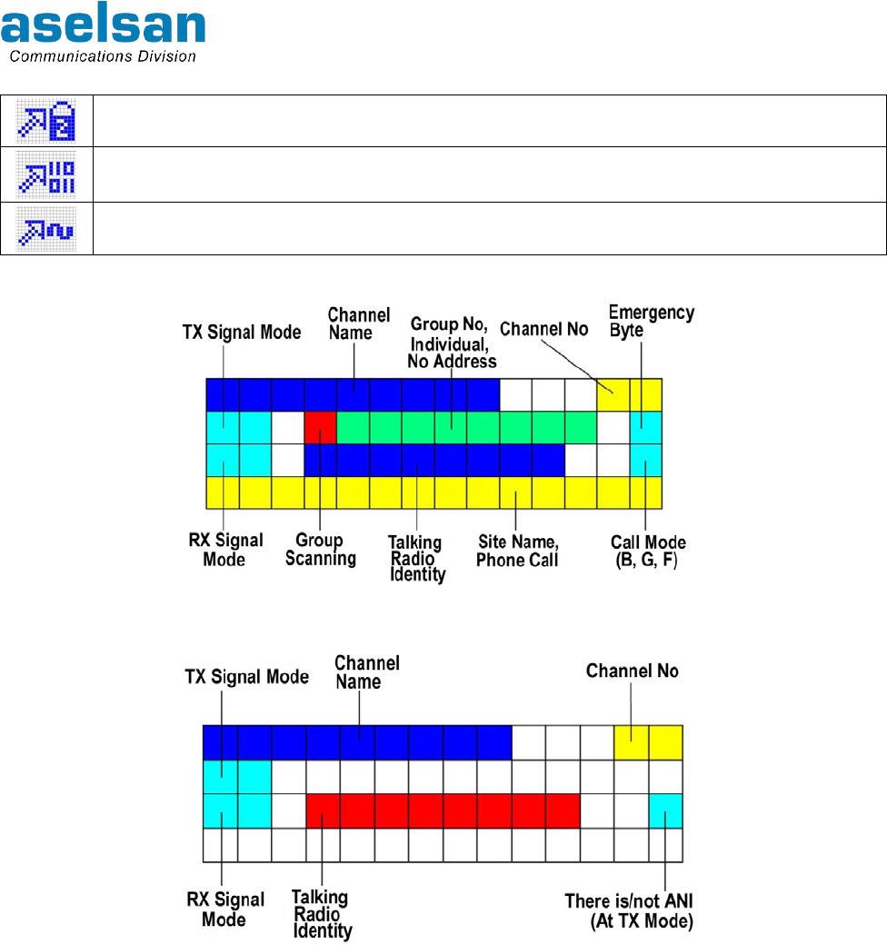
4700 APCO25 CONVENTİONAL HANDHELD RADIO
OPERATING MANUAL
7610-4700-1201
Issue A 2-4
Appears when the radio makes a digital "Private" crypted broadcast at digital mode.
Appears when the radio makes a digital clear broadcast at digital mode.
Appears when the radio starts an analog call.
Figure 2-4: Display Layout at Digital Mode
Figure 2-5: Display Layout at Analog Mode
Lowest row of display is used as "show site name" when the radio is at stand by position.
"MENU"-"INDEX" options do not appear until a key is pressed from keypad.
4700 APCO25 CONVENTİONAL HANDHELD RADIO
OPERATING MANUAL
7610-4700-1201
Issue A 2-5
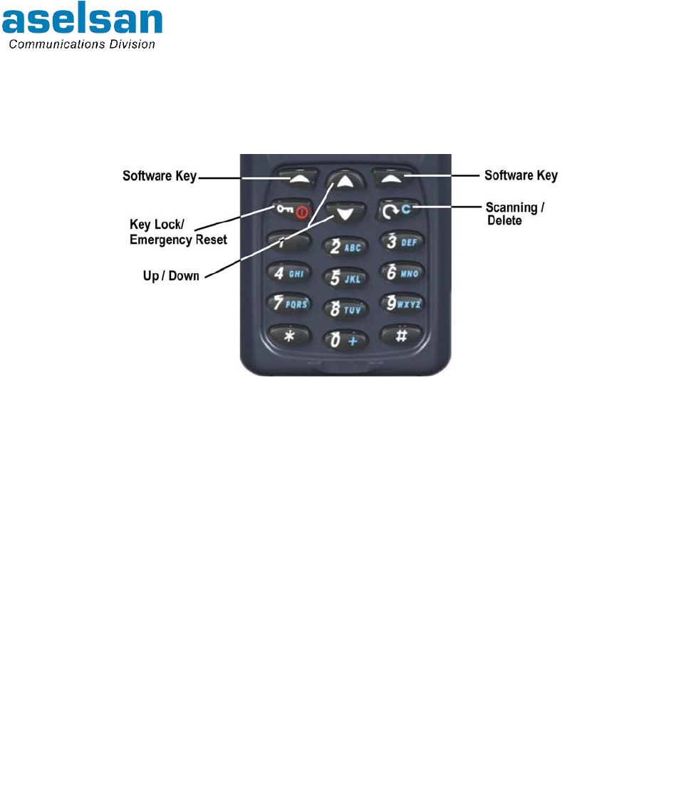
2.1.2 Key Pad
Keypad takes place at the front panel. It is consists of alphanumerical and functional keys,
which can be illuminated and locked. Emergency Call Button is not included in keypad.
Figure 2-6: ASELSAN 4700 APCO25 Conventional Handheld Radio Keypad
Menu functions of the radio are used for the processes like; passing scanning mode,
keypad lock, exiting from emergency call mode, delete etc.
2.1.2.1 Key Lock / Emergency Reset Key
• Press Short: All keys at front panel are locked,
• Press Long: Emergency call reset functions are realized.
If any key is pressed to unlock the keypad a warning message appears at the display.
2.1.2.2 Scanning/Delete Key
While writing message if this key is pressed short it deletes the letter at the left side of the
cursor. If it is pressed longer than 500ms all message is erased.
When it is used as Channel Scanning Key, start/stop channel scanning is done.
2.1.2.3 Software Keys
Their functions are changes according to the existing menu and they are written at the
screen.
2.1.2.4 Up / Down Keys
In menu up-down, at normal operating increase-decrease and at editor right-left functions
are realized by these keys. At APCO25 handheld radios, channel increase decrease
process is functional at channel 16 position.
Up Key:
• At stand-by: It increases the channel number,
• In menu: It goes forward in the menu direction that has smaller shortcut number.
Down Key:
• At stand-by: It decreases the channel number,
• In the menu: It goes forward in the menu direction that has bigger shortcut number.

4700 APCO25 CONVENTİONAL HANDHELD RADIO
OPERATING MANUAL
7610-4700-1201
Issue A 2-6
2.1.2.5 Alphanumerical Keys
Alphanumerical keypad is consisting of 0..9 numbers, * and # keys. It operates as
alphanumerical in short message and index menu. It operates as numerical at the
remaining of menu steps.
2.1.2.5.1 # Key
Digital Mode Functions:
# - Status Info Entrance: It is used to enter radio user's present status info. ”ACTIVE
STATUS” writes at the display and cursor waits for the 2 digit number. When the number is
entered related status message appears at the display.
## - Starting Individual Call: It is used to start an individual call to another radio user.
"INDIVIDUAL:" writes at the screen. Cursor blinks at the lowest row and wait for the
number entrance for maximum 8 digit (‘- - - - - - - -‘) format; it is also possible to reach
number directly from INDEX. After entering last digit or selecting from index, "OK" is
pressed. Meanwhile radio checks if the other radio is turned on, and then transmits "Start
Individual Call" audible warning to the both sides, "individual" writes at the display. Call is
started by pressing PTT Button. When the defined timeout period for the Individual Call
has finished, "Individual Call Finished" audible warning is heard at both sides.
### - Starting Phone Call: "PHONE" writes at the display and Cursor blinks at the lowest
row and wait for the maximum 14 digit number entrance. As the digits are entered screen
forwards to the left. Cursor may be moved though Right- Left with Up-down keys. Phone
call is started by pressing "OK".
Analog Mode Functions:
# - Starting Selective Call: "SELECTIVE CALL" writes at the display and waits for the (2-
6) digit number entrance. After entering the last digit "OK" is pressed to start call.
2.1.2.5.2 * Key
Digital Mode Functions:
* - : Change Group: Cursor waits for the 5 digit number entrance at the screen. If "OK" is
pressed after dialing group number radio settled to that group.
** - : General Call: If ** is pressed, "OK" and "EXIT" appears at the lowest row of. If "OK"
is pressed, user can make general call by pressing PTT Button. If "EXIT" is pressed, radio
exits from this mode.
4700 APCO25 CONVENTİONAL HANDHELD RADIO
OPERATING MANUAL
7610-4700-1201
Issue A 2-7
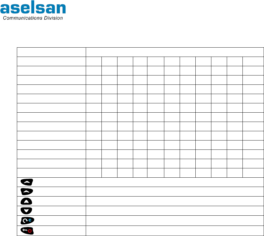
Table 2-2: Alphanumerical Key Definitions at Editor Displays of Menu
Pressing Key Number/definition
Alphanumerical Keys 1 2 3 4 5 6 7 8 9 10 11
1 1
2 A B C 2 a b c Ç ç
3 D E F 3 d e f
4 G H I 4 g h i Ğ ğ İ I
5 J K L 5 j k l
6 M N O 6 m n o Ö ö
7 P Q R S 7 p q r s Ş ş
8 T U V 8 t u v Ü ü
9 W X Y Z 9 w x y z
0 0 + . , : ; ! ” ’
* * / \ - ( ) @
# # ? € $ % & < = >
Its function written at the display (Menu/Select)
Its function written at the display (Index/Exit)
Up/left (Increase) Key
Down/right (Decrease) Key
Scanning / Delete Key
Key Lock Key

4700 APCO25 CONVENTİONAL HANDHELD RADIO
OPERATING MANUAL
7610-4700-1201
Issue A 2-8
2.2 SIDE PANEL
4700 APCO25 Conventional Handheld Radio side panel consists of:
• PTT Button,
• Mode and Power Change Button,
• Option/Monitor Button.
2.2.1 PTT Button
When PTT Button is pressed if the channel is not busy, radio passes transmission from the
existing channel. Transmission interrupted if PTT Button is released.
2.2.2 Mode and Power Change Button
To change output power this button must be pressed long (more than 500msec). To make
short digital clear/digital crypted mode change this button must be pressed short. RF
Power adjustment can make as “High-Middle-Low-High-Middle-Low (H-M-L-H-M-L)”.
2.2.3 Option / Monitor Button
At analog mode:
• When it is pressed short ‘Option (Selective call Stand-by) in use’,
• When it is pressed long (more than 500msec) ‘squelch on’ process achieved.
At digital mode:
• When it is pressed short ‘Option (Individual call Stand-by) in use’,
• When it is pressed long (more than 500msec) "monitor (authorized radio)’ process
achieved.
4700 APCO25 CONVENTİONAL HANDHELD RADIO
OPERATING MANUAL
7610-4700-1201
Issue A 2-9
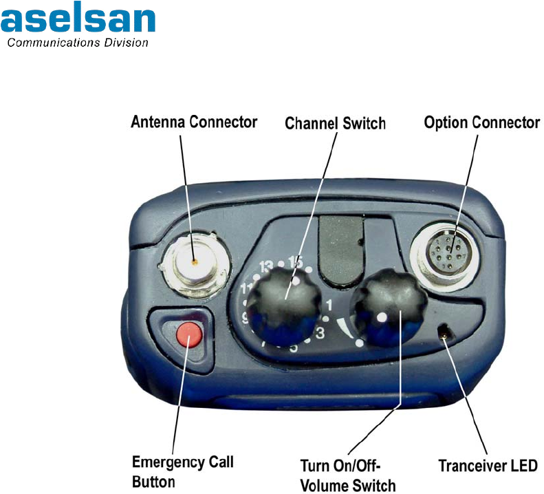
2.3 TOP PANEL
4700 APCO25 Conventional Handheld Radio top panel consists of:
• Emergency Call Button,
• Antenna Connector,
• Channel Switch,
• Turn On/Off-Volume Switch,
• Option Connector,
• Transceiver LED.
2.3.1 Emergency Call Button
At authorized radios if this button is pressed longer than 3 seconds emergency call has
started. When the radio starts emergency call transmission LED lights once for a short
time. If emergency call and channel scanning button is pressed together "EMERGENCY
DELETE" process is achieved.
2.3.2 Antenna Connector
Radio's antenna is attached to that connector. Be sure that antenna attached to the
connector exactly before getting started to use the radio.
2.3.3 Channel Switch
First 15 channels can be selected by channel switch, to select channels bigger that 15
"Channel Switch" is taken to 16th position. At this position required channel number can be
entered by keypad, or by up-down keys user can go to the required channel.
4700 APCO25 CONVENTİONAL HANDHELD RADIO
OPERATING MANUAL
7610-4700-1201
Issue A 2-10
2.3.4 Turn On/Off- Volume Switch
Radio is turned on and off by this switch. And volume level is adjusted with this switch
when the radio is turned on.
2.3.5 Option Connector
Radio's accessories attached and programmed by this connector.
2.3.6 Transceiver LED
LED illuminates blue during receiving, illuminates red at transmission.
2.4 ALERT TONES AND CALL ALERTS
Some alert tones are used to warn user in various kind of situations. Device alert tones
and call alerts can be terminated from menu when it is required. Alert tones and call alerts
list are given in Table 2-3.
Table 2-3: Alert Tones and Call Alerts
ALERT TONES CALL ALERTS
Radio turned on, Digital clear call at crypted radio,
Key pressed, Call at analog channel,
Wrong entrance, Busy channel,
Low voltage, PTT Button is pressed,
Radio turned off, System-fallback switching,
Failure (device). Registered,
Loosing service,
Unauthorized,
Individual Call Started,
Individual Call Ended.
2.5 LIGHTING ALERTS
Some lighting alerts are used to warn user. They can be terminated when it is required.
Lighting alerts list is given below:
• Key pressed (LCD display illuminates)
• Transmission (LED illuminates)
• Receiving (LED and LCD display illuminates)
• Busy channel (LED illuminates)
• Programming (LED illuminates).

4700 APCO25 CONVENTİONAL HANDHELD RADIO
OPERATING MANUAL
7610-4700-1201
Issue A 2-11
2.6 WRITTEN ALERTS
Radio user is sometimes warned by a message appear at the display. List of these
messages are given in Table 2-4.
Table 2-4: Written Warnings
ALERT EXPLANATION
FAILURE X Indicates that Failure Number X has occurred.
Transmission Time Out Some channels have transmission time out period. This warning indicates
that this period has finished.
Individual Call Time Out Appears if both sides don't talk more than 4 seconds in an individual call.
Call Warning Appears when waiting for feedback from system after transmitting call
warning message.
Call Rejected Appears when the other side rejects your call.
Status Request Appears when waiting for response from system after transmitting status
request message.
Status Request Received Appears when status information is requested from system.
No Transmission Frequency Appears when radio is taken to transmission mode while a transmission
frequency is not programmed at the channel.
Battery Discharge! Power Off Appears when the battery voltage is not capable to make transmission.
Battery Discharge’ Low
Power Select Power
Appears to warn user to take output to low power to go on communicating
when the battery is not capable to make transmission at high power.
Settled to Factory Settings Appears when user adjusts settings to factory settings.
Radio Disabled Appears when the radio is disabled.
Key Erased Radio Appears when the radio keys are erased.
Miss Call Appears when the user does not answer a received call.
Short Message 16699999
sent
Indicates that the short message has been transmitted to the related identity.
Short Message 16699999
couldn't send
Indicates that the short message has not been transmitted to the related
identity.
Ready Message 16699999
sent
Indicates that the ready message has been transmitted to the related identity.
Ready Message 16699999
couldn't send
Indicates that the ready message hasn't been transmitted to the related
identity.
Status 16699999 sent Indicates that the status message has been transmitted to the related
identity.
Status 16699999 couldn't
sent
Indicates that the status message hasn't been transmitted to the related
identity.
Call Warning 16699999 sent Indicates that the call warning message has been transmitted to the related
identity.
Call Warning 16699999
couldn't send
Indicates that the call warning message hasn't been transmitted to the related
identity.
Status Request 16699999
sent
Indicates that the status request message has been transmitted to the related
identity.
Status Request 16699999
couldn't send
Indicates that the status request message hasn't been transmitted to the
related identity.
Radio is unauthorized for this
call
Appears when the radio try to make an unauthorized call
Start Announcement Call Appears before starting announcement call.
Called Identity couldn't find Appears if called identification numbered radio is undefined, turned off or out
of coverage area.
Attach CIK Appears if CIK is not attached or cannot be perceived by the device.
Wrong PIN Appears when the dialed PIN code is wrong.
Unprogrammed Group Appears if user wants to dial a group number that is does not included.
Group Monitor On Appears when digital group monitor is turned on.

4700 APCO25 CONVENTİONAL HANDHELD RADIO
OPERATING MANUAL
7610-4700-1201
Issue A 2-12
ALERT EXPLANATION
Group Monitor Off Appears when digital group monitor is turned off.
Channel Monitor On Appears when analog channel monitor is turned on.
Channel Monitor Off Appears when analog channel monitor is turned off.
Keys are locked When the keys are locked appears at the display for information.
It also appears when a key is pressed except "Key Lock" button while the
keys are locked.
Keys are unlocked Appears when the keys are unlocked.
Key has received Appears when a key is received from system through air.
Registering During registering this message appears until a feedback is taken from
system after sending message to the system.
Searching At individual calls during call-setup this message appears until a feedback is
taken from system about the other side status.
Ringing Appears when the other side is ringing.
No answer Message appears at individual calls if the other side does not answer even
though its radio is turned on.
Called number busy Message appears at individual calls if the called radio is busy.
Channel Busy Appears when the radio is taken to transmission mode while the radio has
busy channel lock.
Sending Position (GPS) Appears for a short period during data transmission at GPS channel.
It is preferred not to show the message while the user is in the menu while
the message is being shown.
Battery nearly discharged!
Charge the battery
IF the battery voltage level is under the first bar this message appears once
per minute.
Battery Discharged! Radio
turning off
Appears when the battery is discharged and not replaced to the charger yet.
If battery is replaced to charger but charging has not been started yet "Please
Wait" appears at the display.
Please Turn Off! Deep
Discharge
If the radio is placed to charger for deep discharge radio must be turned off.
Please wait If radio is not turned off during deep discharge device resets and turned on.
After than when the charging is started again is supply is capable to operate
micro but not capable to operate radio this message appears. After a while
battery voltage increases and radio turns back normal operating mode.
Battery must be discharged
with SC4451
Appears when the battery's deep discharge period has arrived.
No connection to repeater At the channels whose receiver and transmitter frequencies are not equal;
after making transmission if no channel active is perceived in 100ms at
receiving mode this message appears.
Enter Scanning List Appears when the radio starts scanning when the scanning list is empty.
Language: English If menu is exited after selecting the language, selected language is shown for
a while.
Full Index Appears when a new record wanted to be added to the full index.

4700 APCO25 CONVENTİONAL HANDHELD RADIO
OPERATING MANUAL
7610-4700-1201
Issue A 2-13
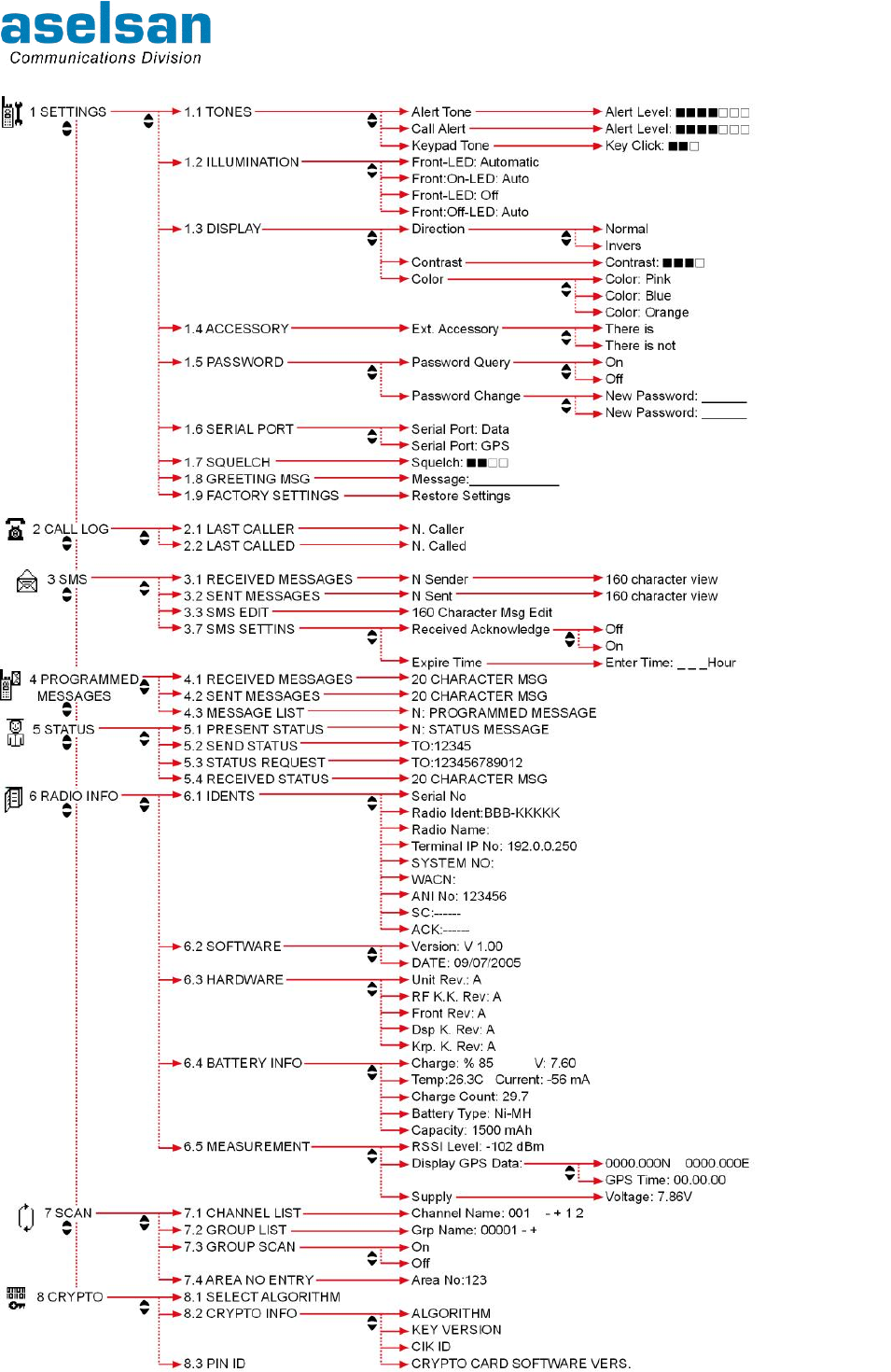
2.7 MENU SCREENS
Menu headings, which can be selected by menu buttons, are given below:
CRYPTO Menu only takes place at the radios that have crypto.
If radio has CRYPTO Menu, SETTING/Password (1.5) sub menu does not appear.
This menu appears at the radios that do not have crypto.
4700 APCO25 CONVENTİONAL HANDHELD RADIO
OPERATING MANUAL
7610-4700-1201
Issue A 2-14
4700 APCO25 CONVENTİONAL HANDHELD RADIO
OPERATING MANUAL
7610-4700-1201
Issue A 3-1
3 MENU USSAGE
All kind of process can be done easily by following the display in the menu. All menu and
sub-menu items have shortcuts. They can be authorized at 1st and 2nd level by
administrator. Administrator can close menus at some radios. These menus can be
selected up to the second digit.
3.1 SETTINGS MENU
Shortcut: 1
Radio user's settings are achieved by this menu.
Tones:
All tone levels of the radio can be adjusted according to user's desire by this menu.
Alert Tone: These alerts are produced by the radio to warn and inform user. It can be
adjusted as 7 leveled.
Call Alert: These alerts are heard when the radio has received a call or starts a call. It can
be adjusted as 7 leveled.
Keypad Tone: When the keys are pressed, "Keypad Tone" alert is heard. It can be
adjusted as 3 leveled.
If these alerts are taken to lowest level no alert tone has heard. If "Alert Tone" and "Call
Alert" warnings are disabled icon appears at the display.
Illumination:
Illuminated Alerts of the radio contain Display, keypad and LED illumination. Lights can be
adjusted according to the user's desire
Front - LED: Automatic: If this option is selected front panel only lights during
communication and when the keys are clicked. LED illuminates only during transmitting
and receiving.
Front: On - LED: Auto: If this option is selected front panel illuminates continuously. LED
illuminates only during transmitting and receiving.
Front - LED: Off: If this option is selected all LED and front panel illuminations turned off.
Front: Off: If this option is selected only LED illuminates.
Front: Off – LED: Auto: If this option is selected front panel (display and keypad) light
continuously.
Display:
Display direction, contrast and color adjustments are achieved by this menu.
Direction: User can select the direction of the display as “normal” and “inverse”. “Inverse”
alternative will be useful while carrying the radio at the waist.
Contrast: Display contrast can be adjusted by up , down keys as 4 leveled.
Color: Front panel lighting color can be adjusted as blue, orange or pink.

4700 APCO25 CONVENTİONAL HANDHELD RADIO
OPERATING MANUAL
7610-4700-1201
Issue A 3-2
Accessory:
External Accessory: This menu option is selected when an external accessory is attached
to the radio, which cannot be found by the radio automatically. Thus radio turns it
loudspeaker off.
Password:
This menu is take place at the radios, which do not have crypto. If password query is
turned on from Password/Password Query sub menu, radio asks password to the user at
the first opening. Existing password can be changed from Password/Password Change.
Serial Port:
Option connector can be connected to different terminals with different rates and serves
different services. For each process connector is taken to appropriate values by this menu.
Data: This menu option is selected for programming of the radio with programming
(AP25TP47) or adjustment (A4700) software or making data communication through radio.
If "data" is not selected software cannot connect with the radio.
GPS: This menu option is selected if GPS receiver is connected to the handheld radio.
Squelch:
Radio's receiver can deafen to prevent random turning on of the squelch at the
electromagnetically polluted environment at analog mode. This process can be done from
squelch sub menu as 4 leveled.
Greeting Message:
10 characters greeting message is entered by this menu. When the radio is turned on,
logo and then greeting message appears.
Figure 3-1: ASELSAN Logo
Factory Settings:
To turn back to the factory settings with the help of this option, new values are appointed
to the following parts:
Keypad Tone = 4
Alert Tone, call alert = 4
Illumination = Front – LED: Auto
LCD Contrast = 2
Serial Port = Data
Squelch = 0
Greeting Message = ASELSAN
Channel list = All conventional channels are included by scanning list, no priority channel
Group scan = On
4700 APCO25 CONVENTİONAL HANDHELD RADIO
OPERATING MANUAL
7610-4700-1201
Issue A 3-3
3.2 CALL LOG MENU
Shortcut: 2
Last Caller Idents:
Received last 10 individual calls or call alert can be seen from this menu.
Last Called Idents:
Transmitted last 10 individual calls or call alert can be seen from this menu.
3.3 SMS MENU
Shortcut: 3
4700 radios can send 160 characters long messages to each other in digital system mode.
Received Message:
Received last 20 messages can be seen from this menu. icon appears if there is any
unread message. icon disappears when all the messages are read.
When the received message menu is full icon light different and warn user to free some
space (deleting some messages) in the list. New messages cannot be received until some
messages deleted.
Send Messages:
Sent last 10 messages can be seen from this menu.
SMS Edit:
Message is written at this menu by using alphanumerical keys. Written message can be
sent to an identity or center by dialing from keypad or selecting from index.
When the message has been sent user is informed by • symbol at the "Send To" list.
SMS Settings:
Received Acknowledge: If user wants to get the "radio to which the message has been
transmitted get the message" info, it can be adjusted by this menu option.
Expire Time: "How long will the system keep the message to transmit it to the other user"
period is determined by this menu.
3.4 PROGRAMMED MESSAGE MENU
Shortcut: 4
4700 APCO25 Conventional Handheld Radios can send and receive predefined
programmed messages at digital system mode. Message length is maximum 20
characters.
Received Message:
Received last 10 programmed messages are seen under this menu. When the list is full
the oldest message is deleted to get new message.

4700 APCO25 CONVENTİONAL HANDHELD RADIO
OPERATING MANUAL
7610-4700-1201
Issue A 3-4
Sent Message:
Sent last 10 programmed messages are seen under this menu. When the transmitted
status message is received by the other radio, user is informed by • symbol.
Message List:
25 pre-defined status messages list is hold under this menu. In order to send status
message required message is selected and the radio ident to which the message will be
sent is dialed or selected from index.
3.5 STATUS MENU
Shortcut: 5
Present Status:
User selects this sub menu for itself among the status messages, which are pre-
programmed to the radio. User can select the appropriate message among the 15 status
messages. Selected status info is transmitted as active status when the radio is
interrogated by center or other radios.
Present status info is erased when the radio turned off.
Send Status:
Selected active status info is transmitted to other radio or center by this menu option. In
order to send active status info radio's identity to which the info will be sent is dialed or
selected from index.
Status Request:
Another radio's active status info is requested by this menu option. To get active status
info radio's identity from which the info will be requested is dialed or selected from the list.
4700 radios can use entered status info during programming.
Received status info is shown at the display for 3 seconds and then transmitted to
"Received Status" sub-menu.
Received Status:
10 status message requested by the radio can be displayed under this menu.
3.6 RADIO INFO MENU
Shortcut: 6
Idents:
• Serial number,
• Radio Ident,
• Radio Name
• Terminal IP number; in case of connecting terminal to the radio for data
communication,
• System No

4700 APCO25 CONVENTİONAL HANDHELD RADIO
OPERATING MANUAL
7610-4700-1201
Issue A 3-5
• WACK
• Analog ANI identity number
is seen under this sub menu.
Software:
Radio software version and date info is given under this menu.
Hardware:
Radio device, board base version info is given under this menu.
Battery Info:
Charge percentage, voltage level, temperature of the battery, drawn current info, charging
number, type, capacity and identity info is given under this menu.
Measurement:
RSSI Level: Broadcast signal level at the channel is seen as dBm.
Display GPS Data: If GPS is connected to the radio; position info read from GPS receiver
is shown as latitude, longitude and GPS clock info is shown as hour:minute:second.
Supply:
Power supply value is given at this menu.
3.7 SCAN MENU
Shortcut: 7
Channel List:
It occurs from simplex and unique repeater channels with 25kHz channel spacing at
analog mode, 12,5kHz channel spacing at digital ctrypted mode.
Channel list determines the priority of the calls received by the radio in channel scan
mode. Analog channel scan can create 1 first priority channel and 1 second priority
channel. During scanning if a call is received from second priority channel, radio leaves
the ordinary channel and goes to the second priority channel and meanwhile it goes on
checking if there is a call from first priority channel.
If it received a call from first priority channel, it leaves the second priority channel and goes
to first priority channel. And it does not interest in other channels until the call at this
channel is finish. When radio receives a broadcast that it can not allow user to listen it
(different tone at analog channel, different group no at digital channel) it goes on scanning
process. Channel scanning becomes unfunctional when a digital or crypted call has been
started to listen at channel.
( - ), ( + ), ( 1 ), ( 2 ) signs take place near the channel number at the list.
• (-) sign means that, channel does not included by the scanning list,
• (+) sign means that, channel included by the scanning list,
• sign means that, this channel is first priority channel during scanning,
• sign means that, this channel is second priority channel during scanning.

4700 APCO25 CONVENTİONAL HANDHELD RADIO
OPERATING MANUAL
7610-4700-1201
Issue A 3-6
Group List:
Groups, which are programmed to the radio, take place in this list.
Group Scan:
Group scanning process at radio is selected by the user. If group scan is selected as "On",
calls received from the groups in the list are listened; if it is selected as "Off", only the
broadcast at the existing group is listened. Calls being started from other groups cannot be
listened.
Area No Entry:
Channel settling and channel based settings of the radio is selected according to the order
determined by the administrator. If this menu usage authority has given to the radio, when
the city traffic number is entered, channels give service in the same number and settling
with the other radios in the city.
3.8 CRYPTO MENU
Shortcut: 8
This menu only takes place at the radios that have crypto.
Select Algorithm:
Selected algorithm can be seen under this menu. One of algorithm "secret" and "private"
leveled algorithm is selected among the existing algorithms by up , down keys and
"OK" software key.
Crypto Info:
Algorithm: Selected algorithm can be seen under this menu.
Key Version: Key sets version info can be seen under this menu.
CIK ID: Attached CIK unit number can be seen under this menu.
Crypto Card Software Version: Attached crypto board's software version info can be seen
under this menu.
PIN ID:
PIN ID that is asked at the opening of the radio can be changed under this menu. To
change PIN ID, attached CIK unit PIN2 no is entered at first and then new PIN info is
entered twice. After completing this process new PIN will be functional at the next opening
of the radio.

4700 APCO25 CONVENTİONAL HANDHELD RADIO
OPERATING MANUAL
7610-4700-1201
Issue A 4-1
4 OPERATING INFORMATION
4700 APCO25 Conventional Handheld Radios have two modes as analog and digital
(clear and crypted); and have two operating modes as system (unique repeater, District
Cover and Wide Area Cover) and direct mode (unique repeater and simplex). If system is
in fallback mode, it is perceived as direct mode operating.
4.1 RADIOS' MODES
4.1.1 Analog Mode
Analog mode is used to communicate with the radios operating in simplex mode or to
communicate with radios through a repeater, which is operating at analog mode in the
area.
Functions like; communication with analog radios, receive/transmit selective call, tone
code squelch, ANI, channel scan (2 level priorities) are achieved at analog mode. User is
warned by audible and visual alerts.
4.1.2 Digital Mode
4.1.2.1 Digital Clear Mode
This mode is to communicate in simplex, direct mode or to communicate with the other
radios at the area through RFSS by disabling crypto board. Digital clear mode – Digital
crypted mode passage is achieved by pressing short to the upper button at the side panel.
Even if the radio does not have crypto module, it can operate in digital clear mode. While
the radio is at Digital clear mode, if its keys are installed, it let user to listen to the received
crypted call.
Functions like group audio call, general audio call, individual audio call, receive/transmit
short message (SMS), receive/transmit programmed message, sending active status,
request/send status, data communication, emergency call, phone connection, call alert,
displaying talking unit identity are achieved when the radio is settled to a digital channel.
4.1.2.2 Digital Crypted Mode
New properties about crypto are added to the digital clear mode functions in this mode.
Digital clear mode – Digital crypted mode passage is achieved by pressing short to the
upper button at the side panel. While the radio is at Digital crypted mode, it let user to
listen to the received digital clear mode.
Functions like group audio call, general audio call, individual audio call, receive/transmit
short message (SMS), data communication, sending active status, request/send status,
emergency call, phone connection, call alert, displaying talking unit identity are achieved
when the radio is at digital crypted mode.

4700 APCO25 CONVENTİONAL HANDHELD RADIO
OPERATING MANUAL
7610-4700-1201
Issue A 4-2
4.2 RADIO'S OPERATING MODES
Radio menus are arranged according to the authorization at system mode. Unauthorized
and unfunctional menus cannot be seen. In case of unauthorized access request (channel,
call etc.) radio gives an audible alert to warn user.
4.2.1 System Mode
Radio communicates with the other radios which are registered to the sites that consist of
repeaters using a lot of different frequencies or just a unique repeater; all services are
given. At the first opening of the radio and passing to the system channels radio is
registered to the system. At the end of registration, registered site name appears at the
lowest row of the radio's display.
4.2.2 Direct Mode
Radio communicates with the other radios through a unique repeater that uses two
frequencies or with the radios that exist at the simplex area. Besides, radio operates as in
direct mode communication when the system is in fallback mode.
4700 APCO25 CONVENTİONAL HANDHELD RADIO
OPERATING MANUAL
7610-4700-1201
Issue A 5-1
5 HOW TO USE
• Be sure that antenna and battery block is connected truly before turning on the radio.
• Turn on the radio by turning the On/Off-Volume Switch in the clockwise direction.
• Enter the attached CIK unit's PIN code.
• Adjust the volume to required level by using On/Off-Volume Switch.
• Channel switch is turned to the required channel. Radio is waited to be registered to
the channel through system.
• To make transmission PTT Button is pressed and it is hold pressed during
transmission. LED at the top of the radio lights red during transmission.
• Output power of the radio can be selected as Low, Medium or High by pressing
Mode and Power Change Button.
• When transmission has finished PTT Button is released to pass receiving position.
LED at the top of the radio lights blue during receiving.
• Radio is turned off by turning On/Off-Volume Switch in the counter-clockwise
direction.
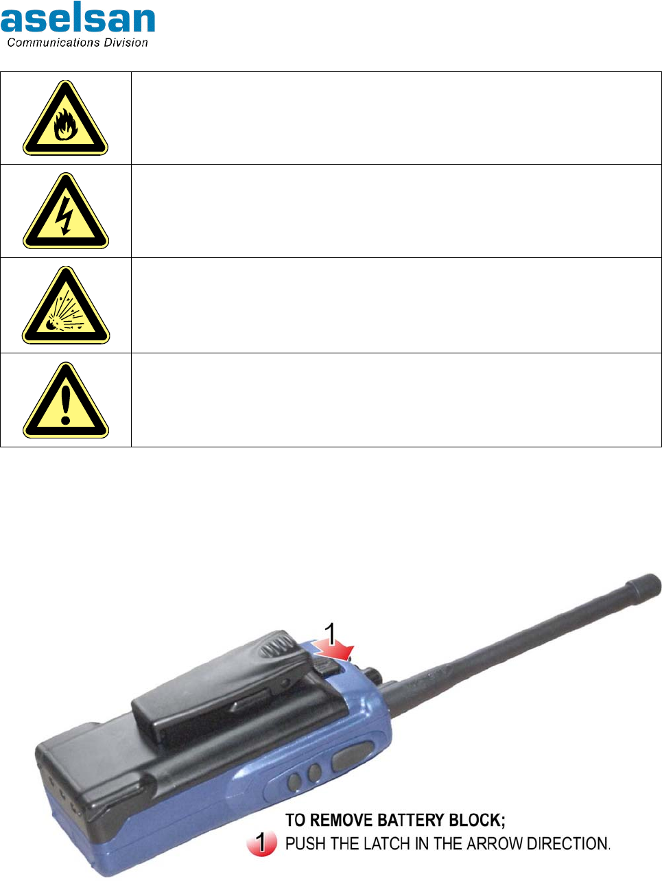
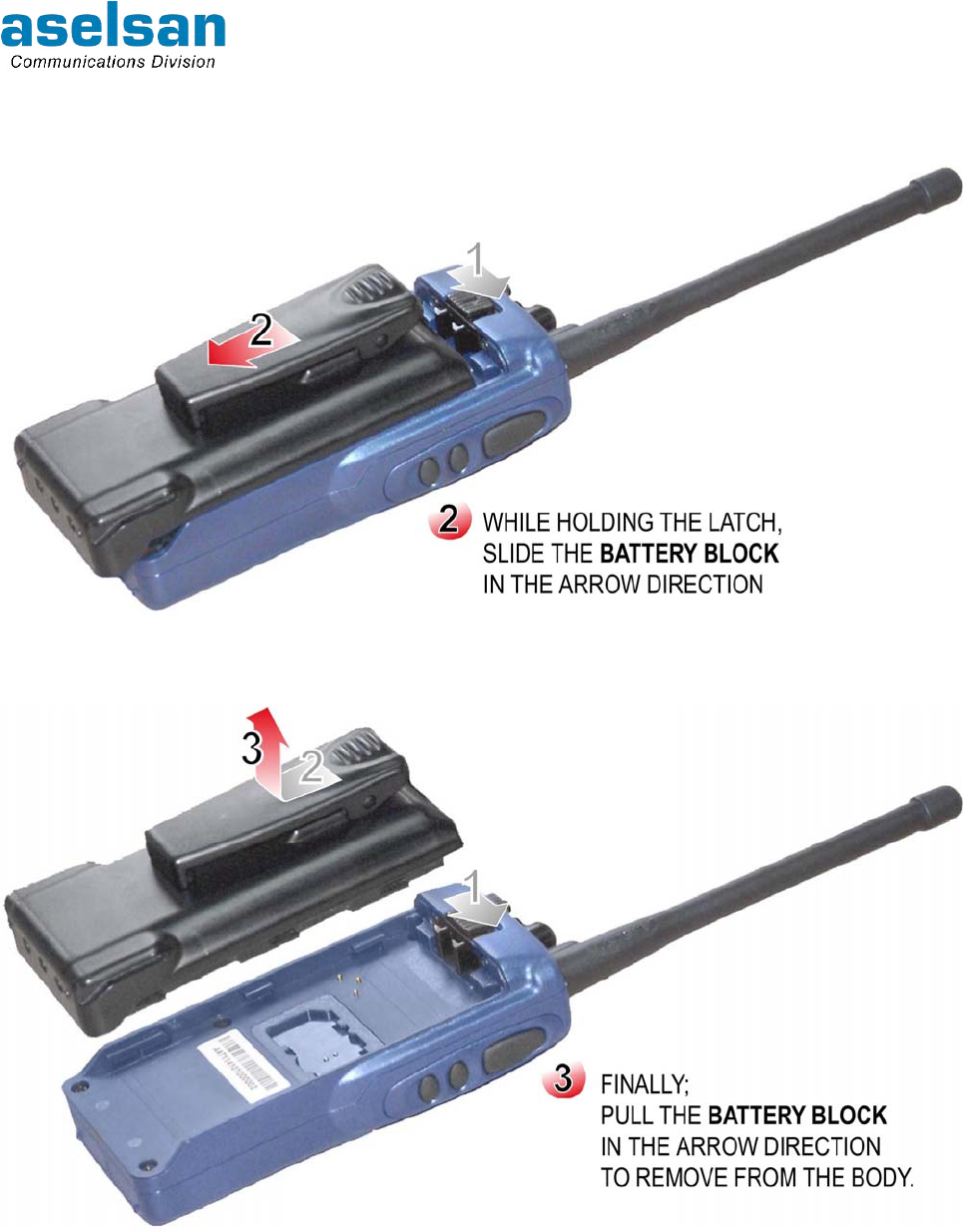
5.1 REMOVING AND ATTACHING OF THE BATTERY BLOCK
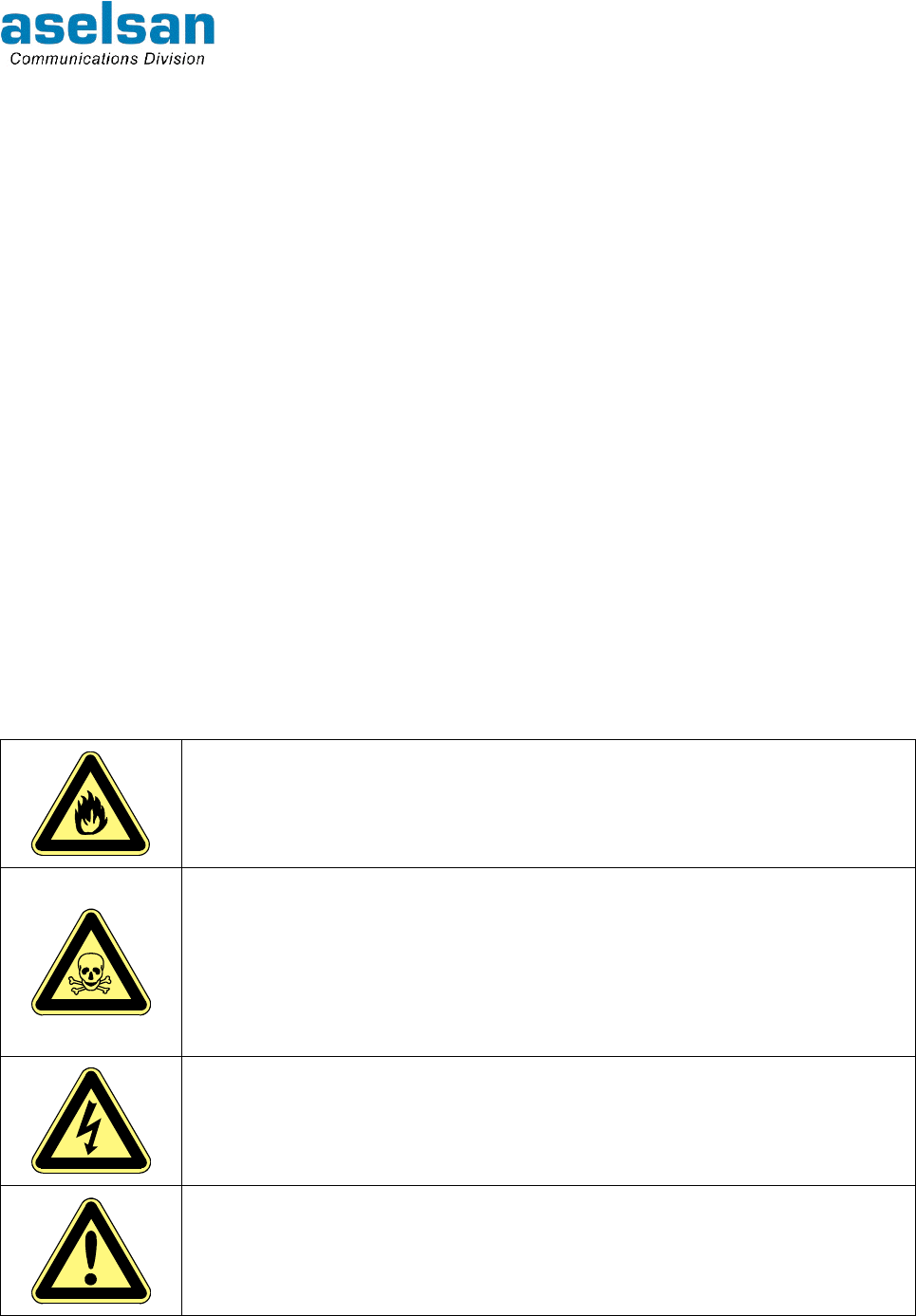
WARNINGS
Do not EVER throw batteries to fire.
At misusages batteries may release damaging chemical gasses. In
this case;
DO NOT BREATHE THE SMOKE,
LEAVE THAT PLACE AS SOON AS POSSIBLE
VENTILATE THE PLACE
Misusage of batteries may cause fire and/or explosion.
Do not try to open battery block. Battery cells contain electrolyte
liquids, which may be damaging for skin and clothes. Do not touch to
the crack battery cells with naked hand.
4700 APCO25 CONVENTİONAL HANDHELD RADIO
OPERATING MANUAL
7610-4700-1201
Issue A 5-2
Do not short cut + and – poles of battery blocks. Making shortcut
between poles with metals like paper pincer, screwdriver may cause
permanent damage and it may cause fire because of high current
capacities of battery blocks.
Battery blocks that are not going to be used anymore must be
destroyed under appropriate circumstances for environment health.
If explosive gasses exit at the atmosphere do not change battery
blocks. Touching of the contacts may cause a spark and it may cause
an explosion.
Battery blocks must be totally discharged before charging them again.
Removing and attaching steps of 4700 APCO25 Conventional Handheld Radio battery
block is given below:
4700 APCO25 CONVENTİONAL HANDHELD RADIO
OPERATING MANUAL
7610-4700-1201
Issue A 5-3

4700 APCO25 CONVENTİONAL HANDHELD RADIO
OPERATING MANUAL
7610-4700-1201
Issue A 5-4
5.2 MAINTENANCE
• Radio does not require periodic maintenance.
• Protect your radio from dust, moisture, dense sun light, extreme heat sources and
liquid materials.
• Use a soft and moistened cloth to clean. Do not use detergent and chemical
solvents.

4700 APCO25 CONVENTİONAL HANDHELD RADIO
OPERATING MANUAL
7610-4700-1201
Issue A 6-1
6 SERVED SERVICES TO THE RADIO USERS
Basic services that are supported by 4700 APCO25 Handheld Radio are summarized in
this section.
6.1 EMERGENCY CALL
Radio demands emergency alarm services by this call. If the red button at the top panel of
the radio is pressed more than 3 seconds, radio transmits "help" info to the emergency call
address (channel), which is determined before. If the call is started at the system channel
in the coverage area it is transmitted to the center, if it is started at direct mode caller
radio's identity appears at all radios' display and caller radio is warned by an audible alert.
To exit from emergency call mode button must be pressed more than 2 seconds.
6.2 GROUP CALL
This call is started to a certain group at Digital Crypted Mode. To start group call:
• ‘*’ button is pressed and the required group number ’00001-65533’ is dialed,
• PTT Button is pressed.
Call can only be listened by the radios, which are included in the group.
6.3 GENERAL CALL
This call is started to all radios at Digital Crypted Mode. To start general call:
• ‘* *’ and ‘OK’ is dialed,
• PTT Button is pressed.
Call can be listened by all radios in the existing channel.
6.4 INDIVIDUAL CALL
This call is started to only one radio at Digital Crypted Mode. To start individual call:
• ‘# #’ is dialed,
• 8 digit radio identity to which the individual will be started is dialed,
• ‘OK' pressed.
After establishing an individual call (audible alert is heard and 'INDIVIDUAL' writes at the
display) PTT Button must be pressed with in 4 seconds. If both sides do not make
transmission in 4 seconds call is terminated.
If there is individual call at the channel other radios cannot make transmission.
6.5 CALL ALERT
Radio leaves a warning message to another radio to call him back. To start call alert at the
authorized radio:
• ‘#’ button is pressed 4 times,
• 8 digit radio identity to which the call alert will be started is dialed,

4700 APCO25 CONVENTİONAL HANDHELD RADIO
OPERATING MANUAL
7610-4700-1201
Issue A 6-2
• ‘OK’ pressed.
After the call alert has been transmitted, caller radio's identity appears at the receiver
radio's display and an audible alert is heard.
6.6 PHONE CALL
Radio demands one-to-one communication at Digital / Crypted Mode by phone call. To
start phone call at the authorized radio:
• ‘# # #’ is dialed,
• Required phone number is dialed,
• ‘OK’ is pressed.
Phone call is made as uni-directional. If PTT Button is pressed, it makes transmission to
phone network and if PTT button is released it listens to the broadcast from phone
network.
Phone call is terminated if phone is closed or button is pressed at radio.
6.7 PRESENT STATUS
Radio user's status info can be selected among the status defined at radio. To select
status info:
• ‘#’ is dialed,
• Required status info between “01-15” is entered,
• ‘OK' is pressed.
If radio is turned off and turned on again, status info is deleted.
6.8 SEND STATUS
To send active status info to another radio user:
• 'Send Status' sub menu is selected from ’Status' menu,
• Radio ident to which the info will be sent is entered,
• ’OK' is pressed.
6.9 STATUS REQUEST
To request the status info of a radio under the system:
• 'Status Request' sub menu is selected from ’Status’ menu,
• Radio ident from which the status info will be requested is entered,
• ’OK' is pressed.
6.10 SHORT MESSAGE (SMS)
Authorized radio can send maximum 160 characters message, which is entered by keypad
to another radio or administration center. Received and sent messages can be seen under
'SHORT MESSAGE' menu.

4700 APCO25 CONVENTİONAL HANDHELD RADIO
OPERATING MANUAL
7610-4700-1201
Issue A 6-3
To send short message:
• ‘SMS EDIT’ sub menu is selected from ‘SMS’ menu,
• Message (maximum 160 characters) is written by alphanumerical keypad,
• ‘OK' is dialed and then the radio ident or center number to which the message will be
sent is entered is entered,
• Message is send by pressing ‘OK’ button.
6.11 PROGRAMMED MESSAGE
Radio can send programmed messages, which are determined during programming, to
another radio or administration center. Received and send programmed messages can be
seen under 'PROGRAMMED MESSAGES' menu.
To send programmed message:
• 'MESSAGE LIST' sub menu is selected under ‘PROGRAMMED MESSAGES’,
• Required message is selected by up , down buttons and 'OK’ key,
• Radio ident or center number to which the programmed message will be sent is
entered,
• Programmed Message is send by pressing ‘OK’ button.
6.12 DATA SERVICES
Message, status message transferred and data communication can be achieved by radio.
6.13 ANALOG CALL
At analog mode channel, when PTT Button is pressed radio makes transmission through
the channel and it gets the analog broadcast at the channel.
6.14 SELECTIVE CALL
At analog mode channel, radio starts a call to another radio by dialing selective call
number. This call's difference from general call is to warn that user to listen carefully. This
call is heard by all radios at the channel.
ANI: Radio's identity info.
SC: Radio's selective call number.
ACK: When radio gets a selective call it sends this number the radio to inform that it has
got the call.
Against the caller radio ANI number and SC number of the radio that it is calling, called
radio responds with its ANI number to inform the caller radio that it has received the call. If
selective call is started to a group ACK is not waited. ANI, SC tone sequences are
displayed as the talking radios identity. To be abler to make selective call radio must be
authorized and at channel parameters, ANI at that channel must be marked.
When SC is received by a radio only the caller radio's ANI info appears at the display.

4700 APCO25 CONVENTİONAL HANDHELD RADIO
OPERATING MANUAL
7610-4700-1201
Issue A 6-4
SC number is given to the radios that have selective call property. SC number is a 2-6 digit
number and can be selected by programming. Each radios SC number is given by a
method that when the last digits are used together it creates a group. In this case groups
are obtained with user number 9, 99, 999, 9999, 99999. SC started to group means that
the call is started to every radios whose SC numbers are starting same. During
programming, group tone at group identity entrance is determined as "0" or "A":
If group tone is programmed as "0" identity is entered as 22000.
If group tone is programmed as "A" identity is entered as 22GGG. thus caller radio dials
group identity as 22***.
To start selective call '#' key is pressed at analog mode and SC number of the other radio
is entered at the screen. Call has begun as soon as the all digits are entered.
While dialing the SC number, the number at the left side of the cursor is deleted by
pressing button.
6.15 TONED CALL
At analog mode channel, if channel is being shared by a lot of user, toned call is used to
achieve communication of the user groups without listening each other when the channel
is not busy. If Tone Code Squelch/Selective Call is disabled by Monitor/Option Button
whole communication at the channel can be listened.
By tone Code Squelch, tone is added to channel's receiver and transmitter frequencies.
Radio receiver only turns on when it gets this tone. Channel tone info is entered with the
frequency info during programming.
6.16 REGISTERING
Radio must be registered to the system to be able to get service from system channels.
After turning on the radio and entering PIN info, radio is registered to the system
automatically. Registered site is appeared at the lowest row of the radio's display.
If radio get out of the site coverage area and enter another site's coverage area it
registered to the new site automatically. Thus user can get service from new system
without changing the channel.
6.17 CALLER IDENT
Radio displays the caller radio's system ident at system or direct mode digital channels; at
analog channels it displays the caller radio's ANI number. For analog ANI display, radio
ANI display must be programmed to the radio.
6.18 REPEAT CALL
If call short message can not be sent because of a barrier it has repeated for 4 times to
establish communication.
6.19 CHANNEL MODE ACCESS
Radio user can follow the call that is has transmitted/received is digital/crypted from
display.

4700 APCO25 CONVENTİONAL HANDHELD RADIO
OPERATING MANUAL
7610-4700-1201
Issue A 6-5
6.20 CHANNEL SCAN
When the radio user is at direct mode channel, it can take the other direct mode channels
to its scanning list and watch if there is a call at any of them. It checks the direct mode
channels that take place in the "channel scanning list" and if there is any broadcast in one
channel, let user to listen to that channel. When any call is received it can respond from
that channel with in scanning delay period (0-10sec). At the end of the time turns back to
its channel and goes on scanning.
Channel scan list can be occurred for all 300 channels or a certain part. At analog usages,
if there is broadcast in more than one channel 2 leveled priority can be given according to
its own priority order. Priority scanning is not valid during digital channels scanning.
While communicating at analog mode, if a call has received from priority channels, radio
passes to the priority channel. 1st and 2nd priority channel can be defined. If channel list
becomes longer it will take time to turn back to the first channel to check.
Channel scan process is started and ended by pressing scanning button that take place at
the front panel. During this process software keys and keypad (except Scan/Delete key)
become unfunctional.
6.21 GROUP SCANNING
Radio user can listen to the digital/crypted calls received from all groups that it is included
or just the group that it exists at the moment according to the group scanning mode. While
the group scanning is in use at the 2nd row of display "*" sign appears near the Group
Number.
6.22 SHORT CUT
All software, hardware, usage info about radio takes place at the menus. All menus are
supported by numerical short cuts. User can reach the required sub menu by entering its
short cut number.
6.23 AUDIBLE ALERTS
Radio gives various audible alerts to inform user. Tones and time periods of each alert
changes.
6.24 LIGHTING ALERTS
Radio gives various lighting alerts to inform user. Red LED lights during transmission,
blues LED lights during receiving. According to the usage requires top panel and front
panel lighting can be adjusted separately for power save.

4700 APCO25 CONVENTİONAL HANDHELD RADIO
OPERATING MANUAL
7610-4700-1201
Issue A 6-6
6.25 TRANSMISSION TIME OUT
To prevent one radio keep busy the channel its transmission time period can be limited.
This period is determined during programming up to 255 seconds. And another time period
can be determined for same radio that it has to wait before passing transmission again.
Thus same radio does not keep busy the channel again for a while. This waiting period
can be adjusted during programming between 0-15seconds. Transmission time out is
notified by an audible alert and transmission is terminated. And radio does not pass
transmission even if its PTT button is pressed, if waiting time period before making
transmission again had been defined.
6.26 BUSY CHANNEL LOCK
Busy Channel Lock is used to prevent radio passing transmission if there is a broadcast in
the channel. Radio that has busy channel lock cannot pass transmission as long as there
is a broadcast at the channel.
6.27 DTMF
At analog mode if radio's alphanumerical keys are pressed during transmission, radio can
produce DTMF tones. But "DTMF transmission authority" must have been given to the
radio during programming. Radio can not make DTMF receive process.
6.28 SELECTING CHANNEL
Radios that have keypad select 300 channels by keypad. First 15 channels can be
selected by Channel Switch. For bigger channels, Channel Switch is taken to position 16
and required channel is dialed from keypad. Radio settled to the selected channel after
entering channel number and pressing "OK".
6.29 KEYLOCK
To prevent involuntary pressing the keys, keypad becomes unfunctional by key lock. This
is achieved by pressing key lock button at the radio. If the same button and "UNLOCK" key
is pressed keypad becomes functional again.
6.30 SIGNAL LEVEL
Received signal level is shown by bars. Besides, its value can be read as dBm from Radio
Info / Measurement sub menu. User can adjust the output power according to the received
signal level for power save or it can learn if it is outside of the coverage area.
6.31 BATTERY CHARGE LEVEL
BB4463 smart battery blocks are used at 4700 APCO25 Conventional Handheld Radios.
Charge level of the battery can be seen at the display. And remaining charging level is
shown as percentage and Volt at the related menu.
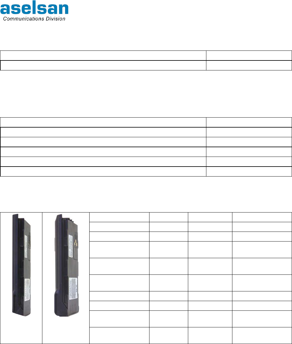
4700 APCO25 CONVENTİONAL HANDHELD RADIO
OPERATING MANUAL
7610-4700-1201
Issue A 7-1
7 SIDE UNITS
Description ASELSAN P/N
ET VHF APCO25 Conventional Crypted Dark Blue 5820-4711-4101
Side units of the handheld radio defined above are defined below.
7.1 ANTENNAS
Description ASELSAN P/N
Helical Antenna 146-174MHz 5986-0597-0154
130±2mm VHF Strong Antenna 146-155MHz 5986-0597-0150
120±2mm VHF Strong Antenna 146-155MHz 5986-0597-0160
115±2mm VHF Strong Antenna 146-155MHz 5986-0597-0169
153±2mm UHF Whip Antenna 406-470MHz 5986-1597-0438
7.2 BATTERY BLOCKS
(*) If this battery is used, radio does not give any information or alert like remaining capacity etc.
Ni-Cd, Ni-MH and Li-Ion batteries are optional. Battery blocks must be fully charged before
first usage. Especially at Ni-MH and Ni-Cd battery block usages, batteries must be
recharged after they are fully discharged. Ni-MH and Ni-Cd battery blocks reach their full
capacity after a few charge-discharge processes.
When discharge period has arrived, user warned by an alert at the display. Batteries must
be discharged by SC4441 desktop charger.
Description Capacity Type No ASELSAN P/N
Ni-Cd 1000mAh BB4463N 5820-4463-0001
Ni-Cd with clips 1000mAh BB4463NK 5820-4463-0002
Ni-Cd with clips
Economical(*) 1000mAh BB4463NKE 5820-4463-0003
Ni-MH High
Capacity 1900mAh BB4463MH 5820-4463-1003
Ni-MH High
Capacity with clips 1900mAh BB4463MHK 5820-4463-1004
Li-Ion 900mAh BB4463L 5820-4463-2001
Li-Ion with clips 900mAh BB4463LK 5820-4463-2002
Li-Ion High
Capacity 1800mAh BB4463LH 5820-4463-3001
Li-Ion
Battery
Block
Ni-Mh
Battery
Block Li-Ion High
Capacity with clips 1800mAh BB4463LHK 5820-4463-3002
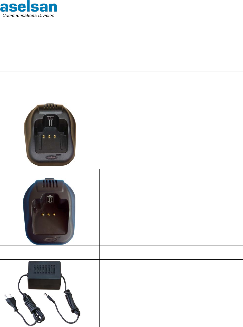
4700 APCO25 CONVENTİONAL HANDHELD RADIO
OPERATING MANUAL
7610-4700-1201
Issue A 7-2
7.3 BATTERY BLOCK CLIPSES
Description ASELSAN P/N
Battery Block Clips Standard “S” 6030-0534-4006
Battery Block Clips “L” 6030-0534-4008
Battery Block Clips “XL” 6030-0534-4007
7.4 CHARGER
ASELSAN approved battery blocks that can be
used with the SC4451 Charger are given in 'Battery
Blocks' section. And the ASELSAN approved
power adapters that can be used with the SC4451
Charger are given in the table below:
Type No Description ASELSAN P/N
SC4451 Desktop Charger
Unit 5820-4451-0001
AC4451 Vehicle Charger
Unit 5820-4451-1001
- Charger Adapter 6625-3000-0015

4700 APCO25 CONVENTİONAL HANDHELD RADIO
OPERATING MANUAL
7610-4700-1201
Issue A 7-3
Ni-Cd, Ni-MH and Li-Ion battery blocks, which have different capacities can be charged
while they are attached to the radio or removed from radio. Charger operates according to
the fast-charging technique. After the battery has been charged, it passes to the buffer
charging. While a smart battery is attached to the charger, it gives information about the
situation (charge has began, charging is going on, charging has finished, discharging has
started, discharging is going on, short circuit, maintenance required, error etc.) by the
lighting alerts. Charging or discharging process can be selected. Attached battery block
can be charged after it is fully discharged.
Charging current is limited by electronic circuits for protection.
Desktop Charger Unit LED alerts are given in Table 7-1.
Table 7-1: Desktop Charger LED Warnings
LED COLOR EXPLANATION
Red (Continuously) Battery block is at fast charge *
Red Continuously, sometimes green Charging process is about to finish (>%90)
Green (Continuously) Charging has finished (Ni-Cd , Ni-MH ->Buffer Charge)
(Battery is full>%95)
Orange (Continuously) Battery block and charger connection error **
Red (Blinks) Battery block temperature is not suitable for fast charging. When the
battery temperature comes to the suitable value range *** device
passes to fast charging automatically.
Red Continuously, sometimes orange This alert goes on for about 3 minutes. Battery must be discharged
for maintenance (Ni-Cd and Ni-MH batteries only).
Red-Green (in order) This alert goes on for 2-10 seconds after the battery is being
attached and removed from charger. At this case if battery is
replaced to the charger, discharging has begun (Ni-Cd and Ni-MH
batteries only).****
Green (Blinks) Discharging (process is being started by the user). Except Li-Ion
batteries.
Orange (Blinks) Battery is failed. Battery couldn't reach to the required voltage value
or there is short circuit between cells. There may also be a
disconnection at the positive end of the battery.*****
* : Because of block-temperature-control fast charge is applied to Ni-Cd or Ni-MH battery block after 3 minutes the
replacing the battery to the charger is the conditions are appropriate.
** : A permanent failure had been occurred at the battery block circuits, unapproved or unprogrammed battery.
*** : Starting fast charge temperature range can change according to the battery type.
**** : If battery is replaced to charger at first and then removed from charger with in 2-10 seconds to start discharge
process, LED begins to blink red-green. To start discharging battery is replaced to the charger again.
***** : This situation occurs at the battery which hadn't been used for long time and thus couldn't reach to the normal
voltage level or at the short circuit occurred battery blocks after 20 minutes. It also occurs at the battery whose positive
end connection has broken, as soon as the battery is placed to the charger.
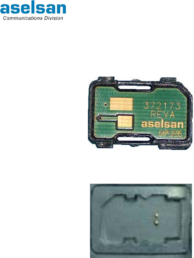
4700 APCO25 CONVENTİONAL HANDHELD RADIO
OPERATING MANUAL
7610-4700-1201
Issue A 7-4
7.5 CIK UNIT
CIK Unit must be replaced to the socket (Figure 7-2) at the rear face of front panel
between front panel and body before getting start to use handheld radio. Otherwise radio
will be unfunctional.
Figure 7-1: CIK Unit
Figure 7-2: Handheld Radio CIK Socket

4700 APCO25 CONVENTİONAL HANDHELD RADIO
OPERATING MANUAL
7610-4700-1201
Issue A 7-5
7.6 ACCESSORIES
Accessories that will be used with the 4700 APCO25 Conventional Handheld Radio are
given below:
ACCESSORY ASELSAN P/N
Handheld Microphone Set (5820-4464-0001) 5820-4464-0001
Inner Helmet Microphone-Earlap Set-PTT 5820-4464-0002
Tube Security Packet 5820-4464-0003
Tube Helmet Set 5820-4464-0004
Collar Microphone/Earlap Set 5820-4464-0005
VIP Ring Microphone/PTT-Earlap Set 5820-4464-0006
Tube Throat Microphone-Earlap Set 5820-4464-0007
Ear Top Band Helmet Set 5820-4464-0008
Tactical Helmet Set 5820-4464-0009
Acrobat-Earlap/Microphone Set 5820-4464-0011
Tube Ordinary Earlap Microphone/PTT Set 5820-4464-0012
Ear Top Ordinary Earlap Microphone/PTT Set 5820-4464-0013
Palm security Kit 5820-4464-0014
Wireless Earlap Microphone Set 5820-4464-0015
7.6.1 Handheld Microphone Set
Conversations can be heard through this
microphone set. Broadcast is transmitted by PTT
Button that takes place at the set and microphone.
It is connected to the radio by spiral cable.
(5820-4464-0001)

4700 APCO25 CONVENTİONAL HANDHELD RADIO
OPERATING MANUAL
7610-4700-1201
Issue A 7-6
7.6.2 Inner Helmet Microphone-Earlap Set
User put this set on to his head. Headphones are
passing beyond the ears at both sides. Metal
connecting headphones stay at the back of the
neck.
Loudspeaker and microphone take place at one
cable, PTT that is in the shape of ring take place at
another cable.
(5820-4464-0002)
7.6.3 Tube Security Packet
Loudspeaker is placed into the ear. This part goes
over to the attachment piece by a transparent
colored spiral cable. PTT that is in the shape of ring
take place at another cable. Microphone is attached
to the clothes with a cable.
(5820-4464-0003)

4700 APCO25 CONVENTİONAL HANDHELD RADIO
OPERATING MANUAL
7610-4700-1201
Issue A 7-7
7.6.4 VIP Ring Microphone/PTT-Earlap Set
Loudspeaker part is paced into the ear.
PTT that is in the shape of ring is at another cable.
Microphone ring is at the PTT.
(5820-4464-0006)
7.6.5 Tube Throat Microphone-Earlap Set
Loudspeaker is placed into the ear. This part goes
over to the clothes attachment piece by a
transparent colored spiral cable.
Microphone is at the elastic band, which wraps up
the throat.
(5820-4464-0007)
7.6.6 Tactical Helmet Set
User put this set on to his head. Microphone comes
through the user mouth; headphones come across
to the ears at both side. Microphone can be
adjusted by twisting. Microphone and loudspeaker
is connected to a cable. PTT that is in the shape of
ring connected to the radio through another cable.
(5820-4464-0009)

4700 APCO25 CONVENTİONAL HANDHELD RADIO
OPERATING MANUAL
7610-4700-1201
Issue A 7-8
INTENTIALLY LEFT BLANK.