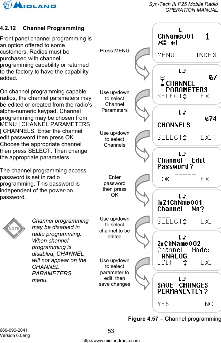
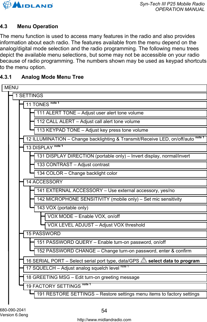
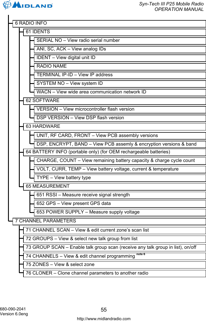
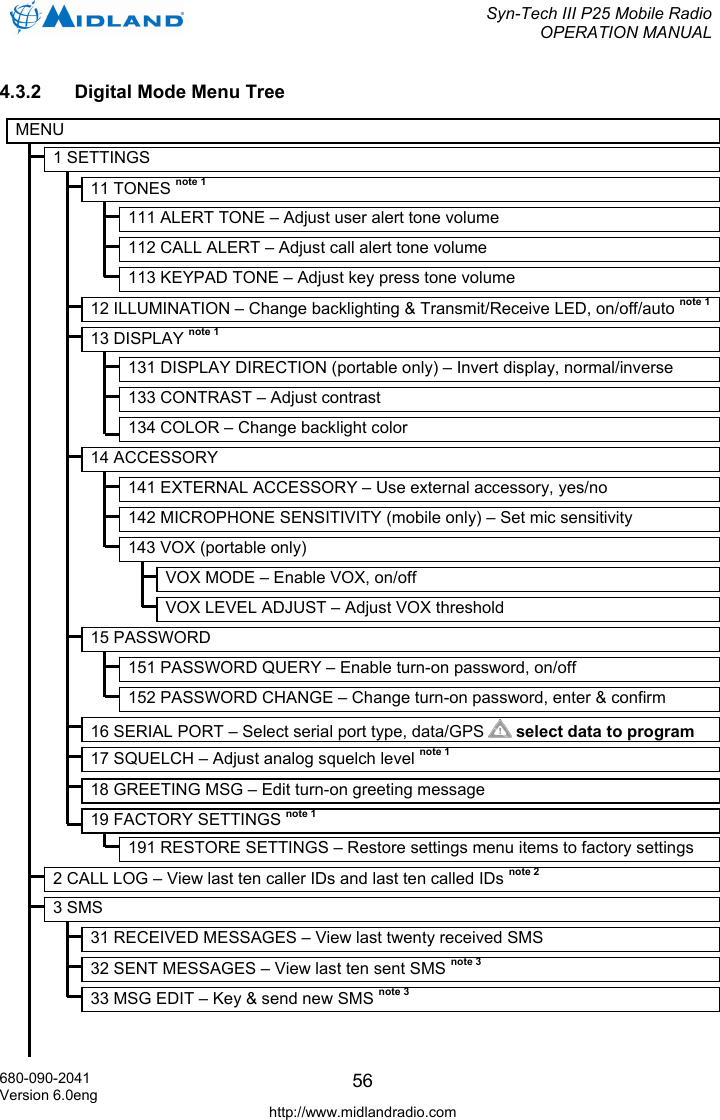
Midland Radio 901090 VHF Mobile Transceiver User Manual STM Operation Manual

Midland Radio Corporation VHF Mobile Transceiver STM Operation Manual

Users Manual

 Syn-Tech III P25 Mobile Radio OPERATION MANUAL   680-090-2041 Version 6.0eng http://www.midlandradio.com Midland Syn-Tech III P25 Mobile Radio    OPERATION MANUAL
 Syn-Tech III P25 Mobile Radio OPERATION MANUAL  680-090-2041 Version 6.0eng http://www.midlandradio.com iPREFACE Thank you for purchasing a Midland Syn-Tech III P25 Mobile Radio. Properly used, this product will give you many years of reliable service. To get the most out of your purchase, be sure to carefully read this manual and keep it on hand for later reference when needed.   Before installing and using your radio, please read this operation manual.  CUSTOMER ASSISTANCE Should you encounter any problems with this product, or are unable to use its features, please review this operation manual. If you require further assistance after reading this manual, please contact your local dealer.  FOR WARRANTY, PRODUCT SERVICE AND ACCESSORY INFORMATION Please contact your local dealer or distributor.   Do not attempt to service any internal parts yourself. This radio should be opened by authorized personnel only.  Your radio is packed and labeled according to the commercial packaging standards.
 Syn-Tech III P25 Mobile Radio OPERATION MANUAL  680-090-2041 Version 6.0eng http://www.midlandradio.com iiIMPORTANT SAFETY INFORMATION  Before installing and using your radio, please read this operation manual.  GENERAL PRECAUTIONS Always use only Midland authorized accessories. Unauthorized accessories have the risk of fire hazard, explosion, personal injury or damage to the radio.  CAUTION Changes or modifications to your radio may void its compliance with government laws/rules and make it illegal to use. Avoid using the radio at temperatures below -30ºC or above 60ºC. Avoid storing the radio at temperatures below -40ºC or above 85ºC.  WARNINGS Your Midland Syn-Tech III P25 Mobile Radio generates electromagnetic RF energy when it is transmitting. To ensure that you and those around you are not exposed to excessive amounts of that energy (beyond recommended allowable limits for occupational use): DO NOT operate your radio without a proper antenna. Otherwise, you can seriously damage your radio. DO NOT touch the antenna when you are transmitting. NEVER connect the transceiver to any AC power source. This may cause an electric shock or fire hazard and will damage your radio. NEVER connect the transceiver to a DC power source either greater than 16 volts or with reverse polarity. Doing so will damage the transceiver. DO NOT attempt to service any internal parts yourself. Please ask your dealer for necessary service. This radio should be opened by authorized personnel only. Please read the installation and operating instructions carefully.
 Syn-Tech III P25 Mobile Radio OPERATION MANUAL  680-090-2041 Version 6.0eng http://www.midlandradio.com iiiFCC EXPOSURE STATEMENTS  Restricted to occupational use to satisfy FCC RF energy exposure limits. The FCC has adopted a safety standard for human exposure to RF energy. Proper operation of this radio under normal conditions results in user exposure to RF energy below the Occupational Safety and Health Act and Federal Communication Commission limits. Mandatory Safety Instructions to Installers and Users: This radio is NOT approved for use by the general population in an uncontrolled environment. This radio is restricted to occupational use and work related operations only. Radio operators must have the knowledge to control their exposure conditions and the exposure conditions of bystanders and/or passengers to satisfy the lower exposure limit allowed for General Population. To comply with FCC RF exposure limits, DO NOT operate the transmitter of this mobile radio when a person outside the vehicle is within the minimum safe distance from the antenna: STM1050B – 22 inches (56 centimeters) STM1115B – 31 inches (79 centimeters) STM4040A/B – 18 inches (45 centimeters) SDT1090 – 31 inches (79 centimeters) The antenna supplied by the manufacturer or radio dealer must be mounted at a location such that during radio transmission, no person or persons can come closer than the above indicated minimum safe distance to the antenna. To comply with current FCC RF exposure limits, the antenna must be installed at or exceeding the minimum safe distance stated above, and in accordance with the requirements of the antenna manufacturer or supplier. Vehicle Installation Instructions: The antenna used for this transmitter must be mounted on the center of the roof ONLY and must be installed in vehicle having the following characteristics in order to prevent bystanders and passengers from being exposed to levels exceeding the limits for General Population/Uncontrolled Exposure environment: 1.  All passengers must be sitting under a solid metal roof. 2.  For rear deck trunk and roof top installations, the antenna must be located at least the minimum safe distance away from rear-seat passengers and bystanders in order to comply with the FCC RF exposure requirements. DO NOT operate the radio without the proper antenna installed. Do not substitute any antenna for the one supplied or recommended by the manufacturer or radio dealer. Antennas used for this transmitter must not exceed an antenna gain of 3 dBi. By not following the antenna recommendations you may be exposing person(s) to excess radio frequency radiation. You may contact your radio dealer or the manufacturer for further instructions. DO NOT transmit more than 50% of total radio use time (50% duty cycle). Transmitting for more than 50% of the time can cause FCC RF exposure compliance requirements to be exceeded. This radio is transmitting whenever the Transmit/Receive LED is red. Pressing the PTT switch on the side of the microphone normally causes the radio to transmit.  The preceding information is provided to make you aware of RF exposure and how to ensure that this radio is operated within FCC RF exposure limits. You, as the qualified end-user of this radio device must control the exposure conditions of bystanders to ensure the minimum separation distance, stated above for satisfying FCC RF exposure compliance, is maintained between the antenna and nearby persons. Transmit only when all person(s) are at least the minimum distance from the properly installed, externally mounted antenna.
 Syn-Tech III P25 Mobile Radio OPERATION MANUAL  680-090-2041 Version 6.0eng http://www.midlandradio.com ivPATENT AND COPYRIGHT STATEMENTS  The AMBE+2™ voice coding Technology embodied in this product is protected by intellectual property rights including patent rights, copyrights and trade secrets of Digital Voice Systems, Inc. This voice coding Technology is licensed solely for use within this Communications Equipment. The user of this Technology is explicitly prohibited from attempting to extract, remove, decompile, reverse engineer of disassemble the Object Code, or in ay other way convert the Object Code into a human readable form. U.S. Patents Nos. #5,870,405, #5826,222, #5,754,974, #5,701,390, #5,715,365, #5,649.050, #5,630,011, #5,581,656, #5,517,511, #5,491,772, #5,247,579, #5,226,084, and #5,195,166
 Syn-Tech III P25 Mobile Radio OPERATION MANUAL  680-090-2041 Version 6.0eng http://www.midlandradio.com vPRODUCT FEATURES Your Midland Syn-Tech III P25 Mobile Radio has the following features:  •  136-174 MHz VHF and 380-470 MHz UHF bands •  Mixed analog and digital mode operation • Easy installation • Low maintenance •  Tri-color LCD display • Full keypad •  High quality audio •  User friendly interface •  Extensive user prompts, alerts and warnings •  Flexible accessory connections • Microprocessor controlled •  DSP based audio • Flash memory •  Synthesized frequency control •  Extensive use of surface mount technology •  PC controlled testing and alignment • CTCSS/CDCSS sub-audible signaling •  2-Tone / 5-Tone analog signaling • Analog DTMF encoding •  Conforms with TIA/EIA-603-A standard in Analog Mode •  Conforms with TIA/EIA-102-CAAB standard in Digital Mode •  Conforms with APCO25 EIA / TIA 102 standards •  Conforms with MIL-STD-810E standards   Full technical specifications are given near the back of this manual.
 Syn-Tech III P25 Mobile Radio OPERATION MANUAL  680-090-2041 Version 6.0eng http://www.midlandradio.com viABBREVIATIONS AND ACRONYMS ACK : Acknowledge AES  :  Advanced Encryption Standard ALG :  Algorithm ANI  :  Automatic Number Identification dBm :  Decibel Milliwatt CIK :  Crypto Ignition Key Identity CDCSS  :  Continuous Digital Coded Squelch System CTCSS  :  Continuous Tone Controlled Squelch System DCS  :  Digital Coded Squelch DES  :  Data Encryption Standard DSP  :  Digital Signal Processing GPS   :  Global Positioning System ID : Identity LCD  :  Liquid Crystal Display MSG :  Message NAC  :  Network Access Code RF :  Radio Frequency RSSI  :  Received Signal Strength Indicator RX :  Receive SC :  Selective Call TCS  :  Tone Coded Squelch  TBX  :  Telephone Branch Exchange TX :  Transmit WACN   :  Wide Area Communication Network
 Syn-Tech III P25 Mobile Radio OPERATION MANUAL  680-090-2041 Version 6.0eng http://www.midlandradio.com viiTABLE OF CONTENTS 1 INTRODUCTION...................................................................................................... 1 1.1 Package Contents........................................................................................... 1 2 INSTALLATION....................................................................................................... 2 3 RADIO CONTROLS AND INDİCATORS................................................................. 3 3.1 Front and Rear Views ..................................................................................... 3 3.2 Button and Key Functions ............................................................................... 4 3.2.1 Emergency Call Button ....................................................................... 4 3.2.2 Alpha-Numeric keypad........................................................................ 4 3.2.3 Up/Down keys..................................................................................... 4 3.2.4 Left soft key (Menu) ............................................................................ 4 3.2.5 Right soft key (Index).......................................................................... 4 3.2.6 Power Adjust (long press)/Mode Change (short press) key................ 5 3.2.7 Monitor (long press)/Call Wait Option (short press) key...................... 5 3.2.8 Keypad Lock (short press)/Emergency Reset (long press) key .......... 5 3.2.9 Scan key............................................................................................. 5 3.2.10 Star key............................................................................................... 6 3.2.11 Pound key........................................................................................... 7 3.3 Display Icons................................................................................................... 9 3.4 Alpha-numeric Keypad Entry........................................................................... 9 4 OPERATION.......................................................................................................... 14 4.1 Basic Operation............................................................................................. 14 4.1.1 Turning the Radio On and Off........................................................... 14 4.1.2 Selecting Zones ................................................................................ 16 4.1.3 Selecting Channels........................................................................... 17 4.1.4 Receiving Signals ............................................................................. 18 4.1.5 Transmitting to Other Radios ............................................................ 20 4.1.6 Selecting Transmit Power................................................................. 24 4.1.7 Selecting Digital Talk Group ................Error! Bookmark not defined. 4.1.8 Selecting Talkaround Transmit Mode ..Error! Bookmark not defined. 4.1.9 Monitoring Channels............................Error! Bookmark not defined. 4.1.10 Selecting Digital Call Wait Option ........Error! Bookmark not defined. 4.1.11 Scanning Channels..............................Error! Bookmark not defined. 4.1.12 Locking the Keypad .......................................................................... 34 4.1.13 Switching to the Home Zone and Channel......... Error! Bookmark not defined. 4.2 Advanced Operation ..................................................................................... 36 4.2.1 Receiving Emergency Calls .............................................................. 36 4.2.2 Transmitting Emergency Calls .......................................................... 37 4.2.3 Receiving Digital Individual Calls .........Error! Bookmark not defined. 4.2.4 Transmitting Digital Individual Calls .....Error! Bookmark not defined. 4.2.5 Transmitting Digital Unaddressed CallsError! Bookmark not defined. 4.2.6 Transmitting Digital Telephone Interconnect Calls....Error! Bookmark not defined.
 Syn-Tech III P25 Mobile Radio OPERATION MANUAL  680-090-2041 Version 6.0eng http://www.midlandradio.com viii4.2.7 Receiving a Digital Call Alert................Error! Bookmark not defined. 4.2.8 Transmitting a Digital Call Alert............Error! Bookmark not defined. 4.2.9 Receiving and Sending Non-voice Messages.... Error! Bookmark not defined. 4.2.10 Channel Programming ...................................................................... 51 4.3 Menu Operation ............................................................................................ 54 4.3.1 Analog Mode Menu Tree .................................................................. 54 4.3.2 Digital Mode Menu Tree.................................................................... 56 5 ACCESSORIES ..................................................................................................... 59 6 STORAGE AND CLEANING PRECAUTIONS...................................................... 60 7 TROUBLESHOOTING........................................................................................... 61 8 SPECIFICATIONS ................................................................................................. 62 8.1 Receiver Technical Specifications................................................................. 64 8.2 Transmitter Technical Specifications............................................................. 65 9 WARRANTY STATEMENT ................................................................................... 66
 Syn-Tech III P25 Mobile Radio OPERATION MANUAL  680-090-2041 Version 6.0eng http://www.midlandradio.com 11 INTRODUCTION 1.1 Package Contents The following items are in your Midland Syn-Tech III P25 Mobile Radio package:    Microphone Hanger Microphone Transceiver Assembly Power Cord
 Syn-Tech III P25 Mobile Radio OPERATION MANUAL  680-090-2041 Version 6.0eng http://www.midlandradio.com 22 Installation Installation should be performed by an Authorized Midland LMR Dealer only.  Radio installation should be performed by qualified and trained personnel, familiar with automotive electronics installation, and FCC RF exposure guidelines. This transceiver should be installed in 12V negative ground vehicles only. Installation instructions are available in the corresponding radio service manual.  Antenna selection, installation and positioning requires knowledge of RF radiation and exposure conditions and should be performed by qualified personnel only. Please consult your dealer or communications coordinator for more information.
 Syn-Tech III P25 Mobile Radio OPERATION MANUAL  680-090-2041 Version 6.0eng http://www.midlandradio.com 33  Radio Controls and Indicators 3.1  Front and Rear Views      Mobile Radio Front View Mobile Radio Rear View F1 Key F2 Key
 Syn-Tech III P25 Mobile Radio OPERATION MANUAL  680-090-2041 Version 6.0eng http://www.midlandradio.com 43.2  Button and Key Functions Below is a brief description of each button or key. For more details of each function refer to the operation section of this manual. Many of the functions may be reassigned or disabled by radio programming or unavailable because of the current analog/digital mode selection. Many of the buttons have a short press, or press and release function, and a long press, or press and hold function. The short press is function is performed if the button is pressed for less than one second, and the long press function is performed if the button is pressed for more than one second. 3.2.1   Emergency Call Button The emergency button initiates emergency mode. The emergency function is only available in digital mode. The emergency key must be pressed for a programmed activation time. Once emergency mode is activated, the radio will switch to the emergency channel and initiate five SBC emergency transmissions. The emergency bit will be set on all user initiated digital transmissions until the emergency is cleared by a long press of the keypad lock key or the radio is turned off. 3.2.2  Alpha-Numeric keypad The alpha-numeric keypad provides direct channel select from standby mode. The alpha-numeric keypad also generates DTMF tones while PTT is pressed on analog channels and enters alpha-numeric characters within other functions. 3.2.3   Up/Down keys The up/down keys provide up/down channel select from standby mode. The up/down keys are generally used to scroll through lists within other functions. 3.2.4   Left soft key (Menu) The left soft key enters the menus from standby mode. The left soft key is generally used as SELECT or OK within other functions. 3.2.5   Right soft key (Index) The right soft key accesses the index (20 unit ID address book) from standby mode. Once the appropriate ID is displayed, press SELECT to edit the entry or the
 Syn-Tech III P25 Mobile Radio OPERATION MANUAL  680-090-2041 Version 6.0eng http://www.midlandradio.com 5(scan) to initiate an individual call to the displayed unit. Up to six of the first entries may be predefined in radio programming and may not be editable. Individual call initiation may be disabled by radio programming.  The right soft key is generally used as EXIT within other functions. The right soft key is used a nuisance channel delete during scan. 3.2.6   F1 Button (Power Adjust/Mode Change) A long press of this key changes the transmit power level. The selections are high, medium and low power. A default power level is set each time the channel is selected.  A short press of this key changes the transmit mode on multi-mode and digital channels. The selections may include analog, digital clear, and digital encrypted transmit modes. A default mode is set each time the channel is selected. 3.2.7   F2 Button (Monitor/Call Wait Option) A long press of this key turns monitor on. The function of the monitor button depends on digital/analog/mixed mode and the radio programming. If monitor is enabled the monitor function may disable the squelch on analog and mixed channels. The monitor function may allow all NACs and talk groups to be received on digital and mixed channels. While monitor is on, a long press of the Monitor/Call Wait key turns monitor off.  A short press of this key turns the call wait option on. The call wait option is available only on digital channels. When the call wait option is on, group calls will be muted. If an individual call (addressed to the radio) or all call is received, the call will be heard and the call wait option will be canceled. While call wait is on, a short press of the Monitor/Call Wait key turns call wait off. 3.2.8   Keypad Lock (short press)/Emergency Reset (long press) key A short press of this key initiates keypad lock. While the keypad is locked, a short press of the Keypad Lock/Emergency Reset key will initiate keypad unlock mode.  While the emergency function is active, a long press of the Keypad Lock/Emergency Reset key will cancel the emergency mode. 3.2.9   Scan key A short press of this key turns on scan. All channels in the selected zone’s scan list will be scanned. If PTT is pressed while scanning, the radio will transmit on the selected
 Syn-Tech III P25 Mobile Radio OPERATION MANUAL  680-090-2041 Version 6.0eng http://www.midlandradio.com 6channel. If PTT is pressed while scan is paused on a channel the radio will transmit on the pause channel. If MENU is pressed scan is canceled. While scan is on, a short press of the Scan key cancels scan.  The Scan key is also used as a clear (long press) or backspace (short press) key during alpha-numeric keypad entry. 3.2.10   Star key The ∗ key is a multi-function key allowing selection of several functions with successive presses. The available functions depend on analog/digital mode. In digital mode the talk group select, all call, talkaround, home and command zone functions may be available. In analog mode the talkaround, home and command zone functions may be available. 3.2.10.1  Switching Talk Group The first press of the ∗ key may prompt “TALKGROUP:” to enter a new talk group. This function is only available in digital mode and the entered talk group must be in the selected zone’s talk group list. 3.2.10.2  Entering/Exiting Unaddressed Voice Call Mode Successive presses of the ∗ key may prompt “ENTER TO ALL CODE MODE?” or “EXIT ALL CODE MODE?” to enter/exit all call mode. This function is only available in digital mode. All call mode implements a call to all talk groups using the channel.  Transmitting all calls may be disabled by radio programming. 3.2.10.3  Entering/Exiting Talkaround Mode Successive presses of the ∗ key may prompt “ENTER TO TALKAROUND MODE?” or “EXIT TALKAROUND MODE?” to enter/exit talkaround mode. This option is not available on simplex (direct) channels. The talkaround function sets the transmitter to the programmed receive frequency/CTCSS/DCS/NAC.  3.2.10.4  Switching to Home Zone and Channel Successive presses of the ∗ key may prompt “GO TO HOME?” to switch to the home zone and channel. 3.2.10.5  Adding to Command Zone Successive presses of the ∗ key may prompt “ADD TO COMMAND ZONE?” to add the current channel to the command zone.
 Syn-Tech III P25 Mobile Radio OPERATION MANUAL  680-090-2041 Version 6.0eng http://www.midlandradio.com 73.2.11   Pound key The # key is a multi-function key allowing selection of several functions with successive presses. The available functions depend on analog/digital mode. In digital mode the zone select, status set, individual call, telephone call and call alert functions may be available. In analog mode the zone select, selective call and two tone call functions may be available.  3.2.11.1 Switching Zones The first press of the # key may prompt “ZONE NO:” to switch zones. The up/down keys will scroll through the available zones. Or, the zone number may be entered using the numeric keypad. The left soft key selects the displayed zone and the right soft key exits without changing zones. 3.2.11.2  Setting Current Status Successive presses of the # key may prompt “CUR. STATUS:” to set the current status. This function is only available in digital mode. The current status is used when sending status to other users, or when other users request the current status. The current status may also be set under MENU | STATUS | PRESENT STATUS.  Sending current status and requesting status from other users may be disabled in radio programming. You may still set current status and receive status messages from other users. 3.2.11.3  Entering Individual Call Mode Successive presses of the # key may prompt “INDIVIDUAL:” to enter individual call mode. This function is only available in digital mode. A unit ID may be entered or selected from the index list. Once a unit ID is selected, the radio will enter individual call mode. The radio will transmit unit to unit calls to the entered unit ID each time PTT is pressed. If PTT is not pressed and no signal is received the individual call mode will time out after ten seconds.  Individual calling may be disabled by radio programming. 3.2.11.4  Initiating a Telephone Interconnect Request Successive presses of the # key may prompt “DIAL TELEPHONE NUMBER” to initiate a telephone call. This function is only available in digital mode. This function initiates a telephone interconnect request on the RF subsystem.
 Syn-Tech III P25 Mobile Radio OPERATION MANUAL  680-090-2041 Version 6.0eng http://www.midlandradio.com 8 Telephone dialing may be disabled or the number of dial digits may be limited by radio programming. 3.2.11.5  Sending a Call Alert Successive presses of the # key may prompt “CALL ALERT:” to initiate a call alert transmission. This function is only available in digital mode.  Call alert transmissions may be disabled by radio programming. 3.2.11.6 Transmitting a Selective Call Successive presses of the # key may prompt “SELECTIVE CALL” to transmit a selective call. This function is only available in analog mode.  Selective calling may be disabled by radio programming. 3.2.11.7  Transmitting a 2-Tone Call Successive presses of the # key may prompt “TWO-TONE CALL” to transmit a 2-tone call. This function is only available in analog mode.  Two-tone calling may be disabled by radio programming.
 Syn-Tech III P25 Mobile Radio OPERATION MANUAL  680-090-2041 Version 6.0eng http://www.midlandradio.com 93.3  Programmable Key Function Assignments The preceding section detailed the default functions for each key. However, many of the keys may be programmed to perform other functions. You may find it convenient to record the new functions of the programmable keys below. Please keep in mind, some functions may not be available because of the analog/digital mode selection.    alpha-numeric keypad:     1 key long press:     2 key long press:     3 key long press:     4 key long press:     5 key long press:     6 key long press:     7 key long press:     8 key long press:     9 key long press:     0 key long press:     ∗ key list:  1.     2.     3.     4.     5.     6.     ∗ key long press:      # key list:  1.     2.     3.     4.     5.     6.      # key long press:      up/down keys:      right soft key:
 Syn-Tech III P25 Mobile Radio OPERATION MANUAL  680-090-2041 Version 6.0eng http://www.midlandradio.com 10   F1 key short press:      F1 key long press:      F2 key short press:      F2 key long press:      scan key:
 Syn-Tech III P25 Mobile Radio OPERATION MANUAL  680-090-2041 Version 6.0eng http://www.midlandradio.com 113.4  Alpha-numeric Keypad Entry The keypad is used to enter alpha-numeric characters within many functions. When the radio is in alpha-numeric mode, successive presses (less than one second apart) of the keys will step through the available characters. Pausing for more than a second will accept the displayed character and move the cursor right one space. A short press of the   (Scan/Clear) key deletes the previous character and moves the cursor left one space. A long press of the   (Scan/Clear) key returns the radio to standby mode.  Table 3.1: Alpha-numeric Keypad Entry Number of Key Presses Keys 1  2 3 4 5 6 7 8 9 10 11 1 Space 1          2  A  B C 2 a b c Ç ç     3 D E F 3 d e f     4 G H I 4 g h i Ğ ğ İ I 5  J  K L 5  j  k  l         6 M N O 6 m n o Ö ö   7  P  Q R S  7  p  q  r  s  Ş ş 8 T U V 8 t u v Ü ü   9 W X Y Z 9 w x y z   0 0 + . , : ; ! ” ’    *  / \ - ( ) @        #  ? € $ % &  < = >
 Syn-Tech III P25 Mobile Radio OPERATION MANUAL  680-090-2041 Version 6.0eng http://www.midlandradio.com 123.5 Display Icons   Table 3.2: Display Icons  This Analog Receive icon appears when an analog signal is received.   This Analog CTCSS Receive icon appears when an analog signal encoded with the correct CTCSS is received.  This Analog CDCSS Receive icon appears when an analog signal encoded with the correct CDCSS is received.  This Digital Receive icon appears when a clear (unencrypted) digital signal is received.  This Digital DES Receive icon appears when an encrypted digital signal using the DES encryption algorithm is received.  This Digital AES Receive icon appears when an encrypted digital signal using the AES encryption algorithm is received.  This Analog Transmit icon appears when the radio is set to transmit in analog mode.  This Analog CTCSS Transmit icon appears when the radio is set to transmit in analog mode with CTCSS.  This Analog CDCSS Transmit icon appears when the radio is set to transmit in analog mode with CDCSS.  This Analog Mixed Reply Transmit icon appears after the radio receives an analog transmission on a mixed mode channel (temporary switch to analog TX).  This Digital Transmit icon appears when the radio is set to transmit in clear digital mode.  This Digital Mixed Reply Transmit icon appears after the radio receives a digital transmission on a mixed mode channel (temporary switch to digital TX).  This Digital DES Transmit icon appears when the radio is set to transmit in digital encrypted mode using the DES encryption algorithm.  This Digital AES Transmit icon appears when the radio is set to transmit in digital encrypted mode using the AES encryption algorithm.
 Syn-Tech III P25 Mobile Radio OPERATION MANUAL  680-090-2041 Version 6.0eng http://www.midlandradio.com 13 This Digital Talkaround Receive icon appears when a clear digital signal is received in direct or talkaround mode.  This Analog Talkaround Transmit icon appears when the radio is set to transmit in analog talkaround mode.  This Digital Talkaround Transmit icon appears when the radio is set to transmit in digital talkaround mode.  This Received Signal Level icon appears when a signal is being received. The number of bars indicates the relative signal strength.  This SMS icon appears after an SMS is received and remains on until the message is read.  This High Power icon appears when high transmit power level is selected.   This Medium Power icon appears when medium transmit power level is selected.  This Low Power icon appears when low transmit power level is selected.   This Tone Squelch icon appears when channel is set to receive a CTCSS or CDCSS signal.  This Call Wait icon appears when call wait mode is selected.   This Alert Tones Off icon appears when alert tones are disabled or silence mode is on.  This Keypad Lock icon appears when keypad lock is selected.   This Scan icon appears when scan is selected.   This Low Battery icon appears when a low voltage condition is detected.
 Syn-Tech III P25 Mobile Radio OPERATION MANUAL  680-090-2041 Version 6.0eng http://www.midlandradio.com 144  OPERATION 4.1 Basic Operation Despite the radio’s advanced feature set, the basic receive and transmit operations can still be quite simple. The radio is capable of distinguishing between analog and digital signals, and the channel may be configured to receive both signal types with no user intervention. The radio channel may also be configured to allow users to transmit analog signals, digital signals, or choose the appropriate transmit mode. The radio may also automatically switch the transmit mode after receiving a different mode signal. The radio will switch back to the selected mode after a time period. 4.1.1  Turning the Radio On and Off Press and release the On/Off Volume Knob to turn the mobile radio on. Press and hold the On/Off Volume Knob at least two seconds to turn the mobile radio off. Rotate the knob clockwise to increase the speaker volume. Rotate the knob counter-clockwise to decrease the speaker volume.  While the radio is performing power-on self-tests, it will display the greeting message and the current zone selection. The radio will power-on to the last selected channel.   If a power-on password has been set, the radio will prompt for power-on password entry when it is turned on. Use the numeric keypad to enter the correct 6-8 digit password, then press the left soft key (OK).  Figure 4.2 – Increase volumeFigure 4.1 – On/Off Figure 4.3 – Decrease volumeEnter 6-8 digit password Press OK to continue Figure 4.4 – Power-on password entry
 Syn-Tech III P25 Mobile Radio OPERATION MANUAL  680-090-2041 Version 6.0eng http://www.midlandradio.com 15If a user password has been set, the radio will prompt for user password entry when it is turned on. Use the numeric keypad to enter the correct 5 digit user password, then press the left soft key (OK).  The power-on and user passwords have similar functions. The power-on password is enabled and changed by the radio programmer. The user password is enabled and changed by the radio user.  Enter 5 digit password Press OK to continue Figure 4.4 – User password entry
 Syn-Tech III P25 Mobile Radio OPERATION MANUAL  680-090-2041 Version 6.0eng http://www.midlandradio.com 164.1.2 Selecting Zones The radio channels may be organized into zones or channel groupings to sort and organize the channels. To select a new zone, press the zone entry key (default:   pound key), then use the up/down keys to scroll through the available zones. The new zone number may also be entered using the keypad. Press the left soft key (OK) to switch to the new zone. The first channel in the new zone will be displayed.  Not sure which zone is currently selected? Press the zone entry key to display the current zone selection. Press exit to return to standby mode.  A new zone may also be selected using zone up/zone down keys.  A new zone may also be selected using MENU | CHANNEL PARAMETERS | ZONES. Press zone entry keyUse up/down to select new zonel Press OK to select new zoneFigure 4.5 – Zone selection
 Syn-Tech III P25 Mobile Radio OPERATION MANUAL  680-090-2041 Version 6.0eng http://www.midlandradio.com 174.1.3   Selecting Channels The  (up/down) keys may be used to increment or decrement the channel selection.  The  (alpha-numeric keypad) may be used to enter a channel number for direct channel selection.  Enter channel number  Press OK  Figure 4.7 – Direct channel number entry
 Syn-Tech III P25 Mobile Radio OPERATION MANUAL  680-090-2041 Version 6.0eng http://www.midlandradio.com 184.1.4 Receiving Signals The radio channel may be configured to receive only analog transmissions, only digital transmissions or both. If the channel is programmed to receive both analog and digital signals (mixed mode receive), the radio will automatically switch to the appropriate mode when receiving the signal. 4.1.4.1 Analog Reception An analog signal exceeding the squelch threshold is indicated by a green Transmit/Receive LED and the Analog Receive icon ( ). On channels programmed for tone squelch, the decoded tone sqelch signal is indicated by the CTCSS Receive icon ( ) or CDCSS Receive icon ( ). A relative value of signal strength is also indicated by the Received Signal Level icon ( ). If the channel’s analog reception parameters are met, the received audio is heard over the speaker. Figure 4.8 – Analog receive display
 Syn-Tech III P25 Mobile Radio OPERATION MANUAL  680-090-2041 Version 6.0eng http://www.midlandradio.com 194.1.4.2 Digital Reception A decoded digital signal is indicated by a green Transmit/Receive LED and the Digital Receive icon ( ). A relative value of signal strength is also indicated by the Receive Signal Strength icon ( ). If the channel’s digital reception parameters are met, the received audio is heard over the speaker. 4.1.4.3  Encrypted Digital Reception A decoded encrypted digital signal is indicated by a green Transmit/Receive LED and the Digital DES Receive icon ( ) or Digital AES Receive icon ( ). A relative value of signal strength is also indicated by the Receive Signal Strength icon ( ). If the channel’s digital reception parameters are met and the encryption keys are matched, the received audio is heard over the speaker.  More information is displayed about received digital signals. While receiving, the talk group ID is displayed in decimal format on the third line ( ), and the source ID is displayed in decimal format on the fourth line (). If the received source ID is in the radio’s address book, the name associated with the source ID will be displayed (). If the received signal has status bits set to 0, the direct or Digital Talkaround icon is displayed to the left of the source ID ( ), otherwise the Digital Receive icon is displayed ( ). To the right of the talk group ID is a single letter indicating the emergency bit is normal ( ) or emergency ( ). To the right of the source ID is a single letter indicating the link control format is a group call ( ) or individual call ().  Figure 4.9 – Digital receive display Figure 4.10 – Encrypted receive display
 Syn-Tech III P25 Mobile Radio OPERATION MANUAL  680-090-2041 Version 6.0eng http://www.midlandradio.com 204.1.5  Transmitting to Other Radios The radio channel may be configured to transmit in analog mode, digital mode or encrypted mode.  Your radio may allow you to select the transmit mode with the TX Mode Change key (default:   short press F1 key). A default transmit mode is chosen by radio programming. The default transmit mode is used each time the channel is selected or radio is turned on. The other available modes may be chosen by successive presses of the TX Mode Change key.  Your radio may automatically switch the transmit mode to the last received mode. This mixed reply transmit mode will be display the Analog Mixed Reply Transmit icon () or Digital Mixed Reply Transmit icon ( ). When a reply timer expires the radio will switch back to the previously selected mode. Press Mode Change key to select next TX mode Press Mode Change key to select next TX Mode Figure 4.11 – Transmit mode selection Figure 4.12 – Mixed reply display
 Syn-Tech III P25 Mobile Radio OPERATION MANUAL  680-090-2041 Version 6.0eng http://www.midlandradio.com 214.1.5.1 Analog Transmissions 1.  Press the TX Mode Change key repeatedly until analog transmit mode is displayed. Depending on channel programming, the analog transmit mode may display the Analog Transmit icon ( ), Analog CTCSS Transmit icon ( ) or Analog CDCSS Transmit icon (). 2.  Ensure that the channel is clear. 3.  Press and hold the push to talk key (PTT). The Transmit/Receive LED will light red while transmitting. 4.  Hold the microphone approximately two inches from your mouth and speak in a clear, normal voice. Keep the PTT switch pressed until you have finished speaking. 5.  Release the PTT switch to return to standby mode and receive any reply. Figure 4.13 – Analog transmit displays
 Syn-Tech III P25 Mobile Radio OPERATION MANUAL  680-090-2041 Version 6.0eng http://www.midlandradio.com 224.1.5.2 Digital Transmissions 1.  Press the TX Mode Change key repeatedly until the Digital Transmit icon ( ) is displayed. 2.  Check that the correct talk group ID is selected. 3.  Ensure that the channel is clear. 4.  Press and hold the push to talk key (PTT). The Transmit/Receive LED will light red while transmitting. 5.  Hold the microphone approximately two inches from your mouth and speak in a clear, normal voice. Keep the PTT switch pressed until you have finished speaking. 6.  Release the PTT switch to return to standby mode and receive any reply. 4.1.5.3 Encrypted Transmissions 1.  Press the TX Mode Change key repeatedly until encrypted transmit mode is displayed. Depending on channel programming, the encrypted transmit mode may display the Digital DES Transmit icon ( ) or Digital AES Transmit icon ( ). 2.  Check that the correct talk group ID is selected. 3.  Ensure that the channel is clear. 4.  Press and hold the push to talk key (PTT). The Transmit/Receive LED will light red while transmitting. 5.  Hold the microphone approximately two inches from your mouth and speak in a clear, normal voice. Keep the PTT switch pressed until you have finished speaking. 7.  Release the PTT switch to return to standby mode and receive any reply.  Figure 4.14 – Digital transmit display Figure 4.15 – Encrypted transmit display
 Syn-Tech III P25 Mobile Radio OPERATION MANUAL  680-090-2041 Version 6.0eng http://www.midlandradio.com 234.1.5.4 Time Out Time A Time Out Time may be programmed to limit the length of continuous transmissions. If the Time Out Time is exceeded, release PTT and wait for the channel to be available again. The Time Out Time may be set from 15-240 seconds in radio programming. 4.1.5.5  Busy Channel Lockout The radio may be programmed to inhibit transmission while the channel is busy. Wait until the channel is clear before transmitting.  Figure 4.16 – Transmit time out Figure 4.17 – Busy channel lockout
 Syn-Tech III P25 Mobile Radio OPERATION MANUAL  680-090-2041 Version 6.0eng http://www.midlandradio.com 244.1.6  Selecting Transmit Power To minimize interference with others, use the lowest transmit power that will provide adequate range. The radio has three transmit power levels which are selected with successive long presses of the Power Change key (Default:   long press F1 key). The actual transmit power associated with each level is set in radio programming.   Press Power Change key to select mid power Press Power Change key to select low power Figure 4.18 – Transmit power selection Press Power Change key to select high power
 Syn-Tech III P25 Mobile Radio OPERATION MANUAL  680-090-2041 Version 6.0eng http://www.midlandradio.com 254.1.7  Selecting Digital Talk Group The default talk group may be set for the channel in radio programming. When the channel is selected, the default talk group is used. If a default talk group was not set for the channel, the radio will use the talk group last selected and displayed.  Each zone in the radio may have a list of allowed talk groups or may have all valid talk groups assigned to it. When the radio is in digital transmit mode, you may select a new talk group from this list by pressing the Talk Group Entry key (default:   star key) until “TALKGROUP:” is displayed. Then use the alpha-numeric keypad to enter the new talk group. Then press the left soft key (OK) to use the entered talk group. If the entered talk group is not in the zone’s talk group list, the radio will not allow the talk group selection.  If a talk group list has been created for the zone, a new talk group may also be selected using the Group Up/Group Down keys. The zone’s talk group list may be viewed and a new talk group may also be selected from MENU | CHANNEL PARAMETERS | TALKGROUPS.  The radio has a talk group scan feature which is on by default. When a signal is received from any talkgroup in the list, the radio will switch to the received talkgroup for the duration of the receive signal and then start the scan delay timer. You may reply using the received talk group during the scan delay time, by pressing PTT. After the scan delay time expires the radio will switch back to the selected talk group. Use MENU | CHANNEL PARAMETERS | TALKGROUP SCAN to turn talk group scan on/off.  Press Group Entrykey Enter new talk group then press OK Figure 4.19 – Group Entry talk group selection
 Syn-Tech III P25 Mobile Radio OPERATION MANUAL  680-090-2041 Version 6.0eng http://www.midlandradio.com 264.1.8  Selecting Talkaround Transmit Mode On channels programmed for repeater operation, the radio may be set to talkaround mode. Talkaround mode allows direct portable to portable communication without accessing the repeater. Press the Talkaround Mode key (default:  star key) until “ENTER TO TALKAROUND MODE?” is displayed then press the left soft key (YES). The radio will switch it’s transmit frequency parameters to those programmed for receive. The Analog Talkaround Transmit icon () or Digital Talkaround Transmit icon ( ) is displayed while talkaround mode is active  The radio will remain in talkaround mode until it is canceled, the channel is changed, the radio is turned off, or a new zone is selected. To cancel talkaround mode, press the Talkaround Mode key until “EXIT TALKAROUND MODE?” is displayed, then press the left soft key (YES).  Press Talkaround Mode key. Select YESFigure 4.20 – Entering talkaround mode Press Talkaround Mode key Select YES Figure 4.21 – Exiting talkaround mode
 Syn-Tech III P25 Mobile Radio OPERATION MANUAL  680-090-2041 Version 6.0eng http://www.midlandradio.com 274.1.9 Monitoring Channels Press the Monitor Change key (default:   long press F2 button) to turn the monitor function on. The function of the monitor button depends on radio programming. If Monitor Channel is enabled, the monitor function will disable the squelch on analog and mixed channels. Press Monitor key to turn monitor on Squelch is opened Press Monitor key to turn monitor off Figure 4.22 – Monitoring channel
 Syn-Tech III P25 Mobile Radio OPERATION MANUAL  680-090-2041 Version 6.0eng http://www.midlandradio.com 28If Monitor All NACs & T.Groups is enabled, the monitor function allows all NACs and talk groups to be received on digital and mixed channels. While monitor is on, a press the Monitor Change key to turn monitor back off.   Press Monitor key to turn on monitor Monitors all talk groups and NACs Press Monitor key to turn off monitor Figure 4.23 – Monitoring all talk groups and NACs
 Syn-Tech III P25 Mobile Radio OPERATION MANUAL  680-090-2041 Version 6.0eng http://www.midlandradio.com 294.1.10  Selecting Call Wait Option Press the Individual Call Wait key (default:   short press F2 button) to turn the call wait option on. The Call Wait icon ( ) is displayed while call wait mode is on. While the call wait option is on, all normal group calls will be muted while the radio waits for an individual. On digital channels, if an individual call (with matching destination ID) or all call is received, the call will be heard and the call wait option will be canceled. On analog channels, if a matching 2-tone or 5-tone call is received the call will be heard and the call wait option will be canceled. While call wait is on, press of the Individual Call Wait key to turn call wait off.  Press Call Wait key to turn on call wait Press Call Wait key to turn off call wait Radio will mute normal group calls Figure 4.24 – Selecting call wait option
 Syn-Tech III P25 Mobile Radio OPERATION MANUAL  680-090-2041 Version 6.0eng http://www.midlandradio.com 304.1.11 Scanning Channels Press the Busy Scan, Priority Scan or Selected Priority Scan key (default:   short press scan key) to turn on scan. The Scan icon ( ) is displayed while scan is active. All channels in the selected zone’s scan list will be scanned. While scan is on, press the scan key to cancel scan. If MENU is pressed, scan is canceled. 4.1.11.1 Busy Scan Busy scan will scan all channels in the selected zone’s scan list. Any priority channel assignments will be ignored. 4.1.11.2 Priority Scan Priority scan will scan all channels in the selected zone’s scan list. The assigned high and low priority channels will be used. While scan is paused on a non-priority channel, the priority channels will be checked for activity. 4.1.11.3  Selected Priority Scan Selected priority scan will scan all channels in the selected zone’s scan list. The selected channel will be assigned and used as the high priority channel. If a low priority channel has been assigned it will also be used. While scan is paused on a non-priority channel, the priority channels will be checked for activity.  Figure 4.25 – Busy scan display Figure 4.25 – Priority scan display Figure 4.25 – Selected priority scan display
 Syn-Tech III P25 Mobile Radio OPERATION MANUAL  680-090-2041 Version 6.0eng http://www.midlandradio.com 314.1.11.4 Transmitting While Scanning If PTT is pressed while scanning the radio will transmit on the selected channel. Press Scan key to turn on scan Press PTT to transmit on the selected channel Release PTT, scan resumes after scan delay Figure 4.26 – Pressing PTT while scanning
 Syn-Tech III P25 Mobile Radio OPERATION MANUAL  680-090-2041 Version 6.0eng http://www.midlandradio.com 32If PTT is pressed while scan is paused on a channel the radio will transmit on the pause channel.   Radio receives signal while scan is on Press PTT to transmit on pause channel Release PTT, scan resumes after scan delay Figure 4.27 – Pressing PTT while scan is paused
 Syn-Tech III P25 Mobile Radio OPERATION MANUAL  680-090-2041 Version 6.0eng http://www.midlandradio.com 334.1.11.5  Editing the Scan List You can add and delete channels from the selected zone’s scan list using MENU | CHANNEL PARAMETERS | CHANNEL SCAN. If a “+” is displayed above the channel name, the channel is currently in the scan list. If “-“ is displayed above the channel name, the channel is not in the scan list. A “1” or “2” indicate priority channel selections.  Use up/down to select Channel ParametersUse up/down to select Channel Scan Select channel to add or remove Press MENU Figure 4.28 – Editing the zone’s scan list
 Syn-Tech III P25 Mobile Radio OPERATION MANUAL  680-090-2041 Version 6.0eng http://www.midlandradio.com 344.1.12  Locking the Keypad Press the   (Keypad Lock) key to lock the alpha-numeric, up/down, scan, and left and right soft keys. While the keypad is locked, press the   (Keypad Lock) key, then press the left soft key (UNLOCK) to unlock the keypad.                    Keypad lock may be disabled in radio programming. The F1 and F2 side buttons may be programmed to lock with the keypad.  Press Keypad Lock to lock the keypad Press Keypad Lock then press UNLOCK to unlock the keypad Figure 4.29 – Locking the keypad
 Syn-Tech III P25 Mobile Radio OPERATION MANUAL  680-090-2041 Version 6.0eng http://www.midlandradio.com 354.1.13  Switching to the Home Zone and Channel Press the Home Zone key (default:   star key) until “Go to Home?” is displayed. Then press the left soft key (OK) to switch to the home zone and channel. If the channel switch is not in the sixteenth position, the radio will switch to the home zone and the channel selected by the switch. The home zone and channel are set in radio programming.  4.1.14  Initiating Silence Mode Press the Silence Mode key to turn on Silence Mode. Silence mode turns off the transmit/busy LED, display backlighting and radio beeps. Press the Silence Mode key again to turn silence mode off.   Press Home Zonekey until “Go To Home?”Press OK to switch to home zone and channel Figure 4.30 – Switching to home zone & channel Press Silence Mode key to turn on Figure 4.31 – Turning Silence Mode on/off Press Silence Mode key againg to turn off
 Syn-Tech III P25 Mobile Radio OPERATION MANUAL  680-090-2041 Version 6.0eng http://www.midlandradio.com 364.2 Advanced Operation Some of the radio’s more advanced operations are listed in this section. Most of these advanced features may be disabled in radio programming. In this case, the feature being described may not appear, or may have a reduced, view only function. 4.2.1  Receiving Emergency Calls When an emergency alert transmission is received, the radio sounds and displays the emergency alert and displays the unit ID of the sender. Pressing any key will silence the alert tone. Press the right soft key to exit the emergency display mode. When a call with the emergency bit set is received the radio displays the call with emergency bit indicator ().  Figure 4.33 – Emergency call display Figure 4.32 – Emergency alert display
 Syn-Tech III P25 Mobile Radio OPERATION MANUAL  680-090-2041 Version 6.0eng http://www.midlandradio.com 374.2.2 Transmitting Emergency Calls Press and hold the   (emergency) key to activate the emergency function. Once emergency mode is activated, the radio switches to the emergency channel set for the selected zone in radio programming or initiates the emergency transmissions on the current channel.  The radio will automatically transmit five emergency alert transmissions and set the emergency bit on all user initiated transmissions until the emergency is cleared. The emergency is cleared by a long press of the   (Keypad Lock) key or by turning the radio off.         Emergency calls may be disabled in radio programming. When emergency calls are disabled the emergency button will not function.  Press and hold Emergency key Hold Keypad Lock for 2 seconds to clear Radio reverts to previous channel Figure 4.34 – Transmitting in emergency mode
 Syn-Tech III P25 Mobile Radio OPERATION MANUAL  680-090-2041 Version 6.0eng http://www.midlandradio.com 384.2.3  Receiving Digital Individual Calls A digital individual call is addressed to a single unit ID rather than a talk group. When this radio receives an individual call from another radio it will automatically switch to individual call mode. The radio will use the received source ID as the destination ID in individual call replies.                If no signal is received and PTT is not pressed for ten seconds, individual call mode will time out.  Press PTT to reply to individual call Individual call time out (after ten seconds) Figure 4.35 – Receiving individual call
 Syn-Tech III P25 Mobile Radio OPERATION MANUAL  680-090-2041 Version 6.0eng http://www.midlandradio.com 394.2.4  Transmitting Digital Individual Calls A digital individual call is addressed to a single unit ID rather than a talk group. To transmit an individual call, press the Individual Entry key (default:   pound key) until “INDIVIDUAL:” is displayed. Enter the unit ID or press the left soft key (INDEX) to select from the address book. Press the left soft key (OK) to enter individual call mode.  Then press PTT to initiate an individual call to the selected unit ID.  An individual call may also be initiated directly from the index by selecting the index entry, then pressing the  (scan key).           If no signal is received and PTT is not pressed for ten seconds, individual call mode will time out.   Individual call initiation may be disabled in radio programming.  Press # key until “Individual:” is displayedEnter unit ID or press INDEX. Press OK to enter individual call mode Figure 4.36 – Entering individual call mode
 Syn-Tech III P25 Mobile Radio OPERATION MANUAL  680-090-2041 Version 6.0eng http://www.midlandradio.com 404.2.5 Transmitting Digital All Calls A digital all call is similar to a group call, except no talk group is specified (reserved talk group $FFFF is used). Any digital radio with matching receive frequency and NAC should receive the all call.   To enter all call mode, press the All Call key (default:   star key) until “ENTER TO ALL CODE MODE?” is displayed, then press the left soft key (YES). The radio will now transmit with reserved talk group $FFFF.  To exit all call mode, press the All Call key until “EXIT ALL CODE MODE?” is displayed then press the left soft key (YES).    All call initiation may be disabled in radio programming.  Press All Call key until “Enter to Unaddressed Voice Call?”Press YES Figure 4.37 – Entering all call mode Press All Call key until “Exit Unaddressed Voice Call?” Press YES Figure 4.38 – Exiting all call mode
 Syn-Tech III P25 Mobile Radio OPERATION MANUAL  680-090-2041 Version 6.0eng http://www.midlandradio.com 414.2.6  Transmitting Digital DTMF/Telephone Dialing Press the Telephone Entry key (default:   pound key) until “DIAL TELEPHONE NUMBER” is displayed. Press the left soft key (OK) then enter the telephone dialing digits. Press the left soft key (CALL). The radio will send a telephone dialing request.               Telephone interconnect calls may be disabled or the number of dial digits may be limited in radio programming.  Press the Telephone Entry key Press OK, enter dial digits,then press CALLFigure 4.39 – Initiating DTMF/telephone dialing
 Syn-Tech III P25 Mobile Radio OPERATION MANUAL  680-090-2041 Version 6.0eng http://www.midlandradio.com 424.2.7  Receiving a Digital Call Alert A call alert is normally used as a low priority request to return the call when it’s more convenient. When a call alert is received the radio will display the unit ID of the initiator. 4.2.8  Transmitting a Digital Call Alert Press the Call Alert key (default:  pound key) until “CALL ALERT:” is displayed. Enter the destination unit ID or press the left soft key for INDEX. Press the left soft key (SEND) to send the call alert. The radio will send up to four call alert requests.    Call alert transmissions may be disabled in radio programming.  Figure 4.40 – Receiving a call alert Press Call Alert key Enter unit ID or press INDEX Press SEND Figure 4.41 – Initiating a call alert request If unit ID is does not answer
 Syn-Tech III P25 Mobile Radio OPERATION MANUAL  680-090-2041 Version 6.0eng http://www.midlandradio.com 434.2.9  Receiving and Sending Non-voice Messages The radio can receive and send three types of non-voice messages when operating in digital mode.  SMS messages are free text messages sent from one radio to another. With SMS messages, the message (up to 160 characters maximum) is entered using the alpha-numeric keypad and transmitted to the other radio.  Predefined messages are common messages among all radios. A predefined message is selected from the predefined message list (of 20 messages of maximum 20 characters) and the message pointer is transmitted to the other radio.  Status messages are common status settings among all radios. A current status is selected by the radio user (of 30 status settings of maximum 20 characters), and may be sent to another radio. Your current status may also be queried by another user.    Both status and predefined messages rely on the receiving radio’s database to determine the message displayed. The message characters are not sent, instead only a pointer of which message should be displayed is sent. For proper status and predefined messaging operation, both the receiving and transmitting radios should be using the same message database.
 Syn-Tech III P25 Mobile Radio OPERATION MANUAL  680-090-2041 Version 6.0eng http://www.midlandradio.com 444.2.9.1  Receiving SMS Messages When an SMS message is received, the radio will display the SMS Message icon ( ). You may view the last twenty received SMS messages from MENU | SMS | RECEIVED MESSAGES.     The   icon indicates unread messages and will remain on until all new messages have been viewed. Within the Received Messages menu, unread messages are preceded by a ∗.  Figure 4.42 – SMS message received Press MENU Use up/down keys to select SMS Use up/down keys to select Received Messages Select message to view Figure 4.43 – Viewing received SMS message
 Syn-Tech III P25 Mobile Radio OPERATION MANUAL  680-090-2041 Version 6.0eng http://www.midlandradio.com 454.2.9.2 Sending SMS Messages SMS messages are sent from MENU | SMS | MSG EDIT. Use the alpha-numeric keypad to enter the desired text, then enter the destination ID or select it from the index.    Sending SMS messages may be disabled by radio programming. When SMS is disabled, SENT MESSAGES and MSG EDIT will not appear on the SMS menu. The radio will still receive SMS and you can view received messages.  Figure 4.44 – Sending SMS message Press MENU Use up/down keys to select SMS Use up/down keys to select Msg Edit Key in message and press OK Enter destination ID or use INDEX then press SEND
 Syn-Tech III P25 Mobile Radio OPERATION MANUAL  680-090-2041 Version 6.0eng http://www.midlandradio.com 464.2.9.3  Receiving Predefined Messages When a predefined message is received, the corresponding text is pulled from the database and displayed along with the source ID. You may also view the last ten received predefined messages from MENU | PREDEFINED MESSAGES | RECEIVED MESSAGES.   Figure 4.45 – Received predefined message
 Syn-Tech III P25 Mobile Radio OPERATION MANUAL  680-090-2041 Version 6.0eng http://www.midlandradio.com 474.2.9.4  Sending Predefined Messages Predefined messages are sent from MENU | PREDEFINED MESSAGES | MESSAGE LIST. Select the desired message from the list then enter the destination ID or select it from the index.    Sending predefined messages may be disabled in radio programming. When predefined messages are disabled, the message list may still be viewed, but predefined messages can’t be sent.  Press MENU Use up/down keys to select Predefined Messages Use up/down keys to select Message List Use up/down to select message and press SELECT Enter destination ID or use INDEX then press SEND Figure 4.46 – Sending predefined message
 Syn-Tech III P25 Mobile Radio OPERATION MANUAL  680-090-2041 Version 6.0eng http://www.midlandradio.com 484.2.9.5  Setting Present Status The radio’s present status may be set from MENU | STATUS | PRESENT STATUS or by pressing the Current Status Entry key (default:   pound key) until “CUR. STATUS:” is prompted.    When the radio is turned on, the present status will be reset to the first status option in the list.  4.2.9.6 Receiving Status When a status message is received, the corresponding text is pulled from the database and displayed along with the source ID. You may also view the last ten received status messages from MENU | STATUS | RECEIVED STATUS.                Figure 4.48 – Receiving status Press MENU Use up/down keys to select Status Use up/down keys to select Present Status Use up/down keys to select new status then press SELECT Figure 4.47 – Selecting current status
 Syn-Tech III P25 Mobile Radio OPERATION MANUAL  680-090-2041 Version 6.0eng http://www.midlandradio.com 494.2.9.7 Sending Status Your current status may be sent from MENU | STATUS | SEND STATUS. Enter the destination ID or use the index to select it, then press SEND to transmit your current status.    Transmitting status may be disabled in radio programming. When status transmissions are disabled, SEND STATUS and STATUS REQUEST will not appear on the STATUS menu.  Press MENU Use up/down keys to select Status Use up/down keys to select Send Status Enter unit ID or use INDEX then press SEND Figure 4.49 – Sending status
 Syn-Tech III P25 Mobile Radio OPERATION MANUAL  680-090-2041 Version 6.0eng http://www.midlandradio.com 504.2.9.8 Requesting Status You may request the current status of another radio from MENU | STATUS | STATUS REQUEST. Enter the destination ID or select it from the index, then press SEND to request another radio’s status.    Transmitting status may be disabled in radio programming. When status transmissions are disabled, SEND STATUS and STATUS REQUEST will not appear on the STATUS menu.  Press MENU Use up/down keys to select Status Use up/down keys to select Status Request Enter unit ID or use INDEX then press SEND Figure 4.50 – Requesting status
 Syn-Tech III P25 Mobile Radio OPERATION MANUAL  680-090-2041 Version 6.0eng http://www.midlandradio.com 514.2.10  Selecting from User Tone List Press the User Selectable Code Entry keys (short or long press of the numeric keypad) to enter a one or two digit User Tone List selection. The name associated with the new tone/NAC selection will be briefly displayed when it is selected and when PTT is pressed. The user selected code will be utilized for the current channel until it is changed to another tone or the radio is reprogrammed. Selecting Code “0” will return the radio to the default tone/NAC selection originally programmed for the channel.                       The ability to use the User Tone List is set in radio programming on a per channel basis. Some channels may not have the User Tone List enabled. Key in the User Tone List number to use a new channel tone/NAC selection Figure 4.51 – Selecting new user tone/NAC Figure 4.52 – Current selection displayed w/PTT Current User Tone List selection is displayed when PTT is pressed User Selectable Code Entry of “0” selects the default channel programming Figure 4.53 – Selecting default tone/NAC
 Syn-Tech III P25 Mobile Radio OPERATION MANUAL  680-090-2041 Version 6.0eng http://www.midlandradio.com 524.2.11  Adding and Deleting from Command Zone Press the Add/Delete from Command Zone key (default:  star key) until “Add to Command Zone?” is displayed. Then press the left soft key (OK) to add the displayed channel to the command zone. Once the command zone contains channels, it will be displayed on the zone selection list.  Channels may be removed from the command zone by selecting the desired channel in the command zone. Then press the Add/Delete from Command Zone key until “Delete from Command Zone” is displayed. Then press the left soft key (OK) to remove the channel from the command zone.          Figure 4.54 – Adding to Command Zone Press Command Zone key until “Add To Command Zone?” Then press YES Use Zone Entry to switch to the Command ZoneFigure 4.55 – Switching to Command Zone Figure 4.56 – Deleting from Command Zone Press Command Zone key until “Delete from Command Zone?” Then press YES
 Syn-Tech III P25 Mobile Radio OPERATION MANUAL  680-090-2041 Version 6.0eng http://www.midlandradio.com 534.2.12 Channel Programming Front panel channel programming is an option offered to some customers. Radios must be purchased with channel programming capability or returned to the factory to have the capability added.  On channel programming capable radios, the channel parameters may be edited or created from the radio’s alpha-numeric keypad. Channel programming may be chosen from MENU | CHANNEL PARAMETERS | CHANNELS. Enter the channel edit password then press OK. Choose the appropriate channel then press SELECT. Then change the appropriate parameters.  The channel programming access password is set in radio programming. This password is independent of the power-on password.    Channel programming may be disabled in radio programming. When channel programming is disabled, CHANNEL will not appear on the CHANNEL PARAMETERS menu.  Figure 4.57 – Channel programming Press MENU Use up/down to select Channel Parameters Use up/down to select Channels Enter password then press OK Use up/down to select channel to be edited Use up/down to select parameter to edit, then save changes
 Syn-Tech III P25 Mobile Radio OPERATION MANUAL  680-090-2041 Version 6.0eng http://www.midlandradio.com 544.3 Menu Operation The menu function is used to access many features in the radio and also provides information about each radio. The features available from the menu depend on the analog/digital mode selection and the radio programming. The following menu trees depict the available menu selections, but some may not be accessible on your radio because of radio programming. The numbers shown may be used as keypad shortcuts to the menu option. 4.3.1  Analog Mode Menu Tree MENU 1 SETTINGS 11 TONES note 1 111 ALERT TONE – Adjust user alert tone volume 113 KEYPAD TONE – Adjust key press tone volume 112 CALL ALERT – Adjust call alert tone volume 19 FACTORY SETTINGS note 1 191 RESTORE SETTINGS – Restore settings menu items to factory settings 18 GREETING MSG – Edit turn-on greeting message 16 SERIAL PORT–Select serial port type, data/GPS  select data to program 15 PASSWORD 151 PASSWORD QUERY – Enable turn-on password, on/off 152 PASSWORD CHANGE – Change turn-on password, enter & confirm 14 ACCESSORY 141 EXTERNAL ACCESSORY – Use external accessory, yes/no 143 VOX (portable only)  VOX MODE – Enable VOX, on/off VOX LEVEL ADJUST – Adjust VOX threshold 13 DISPLAY note 1 131 DISPLAY DIRECTION (portable only) – Invert display, normal/invert 134 COLOR – Change backlight color 133 CONTRAST – Adjust contrast 12 ILLUMINATION – Change backlighting & Transmit/Receive LED, on/off/auto note 1 142 MICROPHONE SENSITIVITY (mobile only) – Set mic sensitivity 17 SQUELCH – Adjust analog squelch level note 1
 Syn-Tech III P25 Mobile Radio OPERATION MANUAL  680-090-2041 Version 6.0eng http://www.midlandradio.com 55  6 RADIO INFO 61 IDENTS SERIAL NO – View radio serial number WACN – View wide area communication network ID IDENT – View digital unit ID ANI, SC, ACK – View analog IDs 65 MEASUREMENT 651 RSSI – Measure receive signal strength 653 POWER SUPPLY – Measure supply voltage 652 GPS – View present GPS data 64 BATTERY INFO (portable only) (for OEM rechargeable batteries) CHARGE, COUNT – View remaining battery capacity & charge cycle count TYPE – View battery type VOLT, CURR, TEMP – View battery voltage, current & temperature TERMINAL IP-ID – View IP address RADIO NAME SYSTEM NO – View system ID 63 HARDWARE UNIT, RF CARD, FRONT – View PCB assembly versions DSP, ENCRYPT, BAND – View PCB assemly & encryption versions & band 62 SOFTWARE VERSION – View microcontroller flash version DSP VERSION – View DSP flash version 7 CHANNEL PARAMETERS 71 CHANNEL SCAN – View & edit current zone’s scan list 72 GROUPS – View & select new talk group from list 73 GROUP SCAN – Enable talk group scan (receive any talk group in list), on/off 74 CHANNELS – View & edit channel programming note 6 75 ZONES – View & select zone 76 CLONER – Clone channel parameters to another radio
 Syn-Tech III P25 Mobile Radio OPERATION MANUAL  680-090-2041 Version 6.0eng http://www.midlandradio.com 564.3.2  Digital Mode Menu Tree   MENU 1 SETTINGS 11 TONES note 1 111 ALERT TONE – Adjust user alert tone volume 113 KEYPAD TONE – Adjust key press tone volume 112 CALL ALERT – Adjust call alert tone volume 19 FACTORY SETTINGS note 1 191 RESTORE SETTINGS – Restore settings menu items to factory settings 18 GREETING MSG – Edit turn-on greeting message 16 SERIAL PORT–Select serial port type, data/GPS  select data to program 15 PASSWORD 151 PASSWORD QUERY – Enable turn-on password, on/off 152 PASSWORD CHANGE – Change turn-on password, enter & confirm 14 ACCESSORY 141 EXTERNAL ACCESSORY – Use external accessory, yes/no 143 VOX (portable only) VOX MODE – Enable VOX, on/off VOX LEVEL ADJUST – Adjust VOX threshold 13 DISPLAY note 1 131 DISPLAY DIRECTION (portable only) – Invert display, normal/inverse 134 COLOR – Change backlight color 133 CONTRAST – Adjust contrast 12 ILLUMINATION – Change backlighting & Transmit/Receive LED, on/off/auto note 1 142 MICROPHONE SENSITIVITY (mobile only) – Set mic sensitivity 17 SQUELCH – Adjust analog squelch level note 1 2 CALL LOG – View last ten caller IDs and last ten called IDs note 2 3 SMS 31 RECEIVED MESSAGES – View last twenty received SMS 33 MSG EDIT – Key & send new SMS note 3 32 SENT MESSAGES – View last ten sent SMS note 3
 Syn-Tech III P25 Mobile Radio OPERATION MANUAL  680-090-2041 Version 6.0eng http://www.midlandradio.com 57  5 STATUS 51 PRESENT STATUS – View and set present status 54 RECEIVED STATUS – View last ten received status messages 53 STATUS REQUEST – Request another radio’s present status note 5 52 SEND STATUS – Send present status to another radio note 5 4 PREDEFINED MESSAGES 41 RECEIVED MESSAGES – View last ten received messages 43 MESSAGE LIST – View and send predefined message note 4 42 SENT MESSAGES – View last ten sent messages note 4 6 RADIO INFO 61 IDENTS SERIAL NO – View electronic serial number WACN – View wide area communication network ID IDENT – View digital unit ID ANI, SC, ACK – View analog IDs 65 MEASUREMENT 651 RSSI – Measure receive signal strength 653 POWER SUPPLY – Measure supply voltage 652 GPS – View present GPS data 64 BATTERY INFO (portable only) (for OEM rechargeable batteries) CHARGE, COUNT – View remaining battery capacity & charge cycle count TYPE – View battery type VOLT, CURR, TEMP – View batter voltage, current and temperature TERMINAL IP-ID – View IP address RADIO NAME SYSTEM NO – View system ID 63 HARDWARE UNIT, RF CARD, FRONT – View PCB assembly versions DSP, ENCRYPT, BAND – View PCB assemly & encryption versions & band 62 SOFTWARE VERSION – View microcontroller flash version DSP VERSION – View DSP flash version
 Syn-Tech III P25 Mobile Radio OPERATION MANUAL  680-090-2041 Version 6.0eng http://www.midlandradio.com 58               note 1 These selections are unavailable when the Settings option is disabled in radio programming.  note 2  This selection is unavailable when the Call Log option is disabled in radio programming.  note 3  These selections are unavailable when the SMS option is disabled in radio programming.  note 4  These selections are limited or unavailable when the Predefined Messages option is disabled in radio programming.  note 5  These selections are unavailable when the Status option is disabled in radio programming.  note 6  This selection is unavailable when the Channel Programming option is disabled in radio programming.  note 7  This selection is only available when encryption option is purchased.   8 ENCRYPTION note 7 81 ALGORITHM – View and select available encryption types 82 ENCRYPTION INFO – View encryption information, Algorithm ID and Key ID 7 CHANNEL PARAMETERS 71 CHANNEL SCAN – View & edit current zone’s scan list 72 GROUPS – View& select new talk group from list 73 GROUP SCAN – Enable talk group scan (recieve any talk group in list), on/off 74 CHANNELS – View & edit channel programming note 6 75 ZONES – View & select zone 76 CLONER – Clone channel parameters to another radio
 Syn-Tech III P25 Mobile Radio OPERATION MANUAL  680-090-2041 Version 6.0eng http://www.midlandradio.com 595 ACCESSORIES Original Midland accessories give you operational efficiency, flexibility and reliability in difficult working conditions.  ACCESSORY MIDLAND P/N Microphone ACC4425 Loudspeaker ACC1425 Under dash mounting kit 560-090-0091 Trunk mounting kit  90-2528 Power cable assembly 90-0042 Programming software  MRP P25 Programming cable  ACC2600 Cloning kit  ACC2305 Test and alignment adaptor  ACC2205
 Syn-Tech III P25 Mobile Radio OPERATION MANUAL  680-090-2041 Version 6.0eng http://www.midlandradio.com  606  STORAGE AND CLEANING PRECAUTIONS  Keep the radio clean and away from dust, humidity, dense sunlight, extreme heat sources and liquids.  Avoid exposing the radio and accessories to cleaning solvents, aerosol sprays, adhesive agents, paints etc. Chemical reactions with such agents will destroy seals, case, display and finish.  If the radio is exposed to dirt, wipe with a soft and moist cloth at least once a week to prevent build-up of dirt and dust deposits.  Your radio does not require any periodic maintenance.
 Syn-Tech III P25 Mobile Radio OPERATION MANUAL  680-090-2041 Version 6.0eng http://www.midlandradio.com  617 TROUBLESHOOTING PROBLEM POSSIBLE CAUSE(s)  SOLUTION(s) No display on LCD when radio is turned on. Fuse is blown or connections are insecure.  Check fuse and connections. No sound from Loudspeaker. Volume level is too low.  or Squelch level is too high.  or Radio is set for external accessory. Adjust volume level.  or Adjust squelch level.  or Turn off external accessory.  or Check speaker connections. No response to key press.  Key lock is on.  Unlock the keypad. No answer to calls. Out of range of other stations or signal is blocked by terrain. Switch to high output power.  or Move closer until you have a “line-of-sight” to the other station. Radio to PC connection fails. Serial port is set for GPS receiver. Change serial port selection to “DATA”.
 Syn-Tech III P25 Mobile Radio OPERATION MANUAL  680-090-2041 Version 6.0eng http://www.midlandradio.com  628 SPECIFICATIONS GENERAL SPECIFICATIONS Modulation  16K0F3E, 11K0F3E , 8K0D1E, 8K0F1E Data Rate  P25 : 9.6 kb/s Symbol Rate  P25 : 4.8 kb/s Protocol  Project 25-CAI : 4.4 kb/s IMBE Encryption Algorithms  DES-OFB, AES Channel Capacity  999 Operating Voltage Range  13.6 Vdc ± % 20 (10.88-16.32 Vdc) Standby Current Drain (backlight off)  ≤ 0.4 A  RX Current Drain      ≤ 1.5  TX Current Drain      ≤ 8.5 A  Display  64x128 pixel LCD Keypad  20 key, back lit Dimensions (HxWxL) (projections not included) 1.8x6.5x6.5 in (46x165x165 mm)  Weight   1.50 kg     ENVIROMENTAL SPECIFICATIONS Operating Temperature Range  -30°C / +60°C Storage Temperature Range  -40°C / +85°C Humidity  % 95, 50°C ESD  IEC 801- 2KV Water and Dust Protection  IP65, MIL-STD
 Syn-Tech III P25 Mobile Radio OPERATION MANUAL  680-090-2041 Version 6.0eng http://www.midlandradio.com  63 MILITARY STANDARDS 810C/D/E/F   MIL-STD 810C  MIL-STD 810D  MIL-STD 810E  MIL-STD 810F  Method Proc./ Cat.  Method  Proc./ Cat.  Method  Proc./ Cat.  Method  Proc./ Cat. Low Pressure  500.1 I 500.2 II 500.3 II 500.4 II High Temperature  501.1 I, II 501.2 I/A1, II/A1  501.3  I/A1, II/A1  501.4  I/Hot, II/Hot Low Temperature  502.1 I 502.2 I/C1, II/C2  502.3  I/C1, II/C2  502.4  I/C1, II/C2 Temperature Shock  503.1 – 503.2 I/A1-C2 503.3 I/A1-C2 503.4 I/Hot-C2 Solar Radiation  505.1 II 505.2  I  505.3  I  505.4  I Rain  506.1 I, II 506.2 I, II 506.3 I, II 506.4 I, III Humidity  507.1 II 507.2 II 507.3 II 507.4 – Salt Fog  509.1 – 509.2 – 509.3 – 509.4 – Sand and Dust  510.1  I  510.2  I, II  510.3  I, II  510.4  I, II Vibration  514.2  VIII/F, XI/H  514.3  I/10, II/3  514.4  I/10, II/3  514.5  I/24, II/5 Shock   516.2  I, II, V  516.3  I, V, VI  516.4  I, V, VI  516.5  I, V, VI
 Syn-Tech III P25 Mobile Radio OPERATION MANUAL  680-090-2041 Version 6.0eng http://www.midlandradio.com  648.1  Receiver Technical Specifications RECEIVER SPECIFICATIONS  VHF UHF Frequency Range  136-174 MHz  380-470 MHz Frequency Separation  Full Bandsplit  Full Bandsplit Channel Spacing  12.5 / 20 / 25 / 30 kHz  12.5 / 20 / 25 / 30 kHz Frequency Step  2.5 / 3.125 kHz  2.5 / 3.125 kHz Rated Audio Output Power *  7.5 W / 8 Ω  7.5 W / 8 Ω Frequency Stability *  (-30°C / +60°C; 25°C ref)  ± 2.5 ppm  ± 1.5 ppm Analog Sensitivity *       12 dB SINAD Digital Sensitivity **      5% BER    1% BER  ≤ -119 dBm  ≤ -120 dBm ≤ -117 dBm  ≤ -118 dBm  ≤ -119 dBm ≤ -116 dBm Adjacent Channel Rejection    Analog 25 kHz channel *    Analog 12.5 kHz channel *    Digital 12.5 kHz channel **   ≥ 75 dB ≥ 63 dB ≥ 63 dB  ≥ 75 dB ≥ 63 dB ≥ 63 dB Intermodulation Rejection *  ≥ 75 dB  ≥ 75 dB Spurious Response Rejection*  ≥ 85 dB  ≥ 85 dB Hum and Noise Ratio    Analog 25 kHz channel *    Analog 12.5 kHz channel *    Digital 12.5 kHz channel **  ≥ 48 dB ≥ 42 dB ≥ 50 dB  ≥ 42 dB ≥ 36 dB ≥ 50 dB Audio Distortion *  ≤ 3 %  ≤ 3 %    * Measured in the analog mode per EIA-603 under nominal conditions.   ** Measured in the digital mode per TIA-102.CAAA under nominal conditions.
 Syn-Tech III P25 Mobile Radio OPERATION MANUAL  680-090-2041 Version 6.0eng http://www.midlandradio.com  658.2 Transmitter Technical Specifications TRANSMITTER SPECIFICATIONS  VHF UHF Frequency Range  136-174 MHz  380-470 MHz Frequency Separation  Full Bandsplit  Full Bandsplit Channel Spacing  12.5 / 20 / 25 / 30 kHz  12.5 / 20 / 25 / 30 kHz Frequency Step  2.5 / 3.125 kHz  2.5 / 3.125 kHz Rated RF Output Power *    5-50 W/10-110W  5-40 W Frequency Stability *  (-30°C / +60°C; 25°C ref)  ± 2.5 ppm  ± 1.5 ppm Modulation Limiting *    Analog 25 kHz channel    Analog 12.5 kHz channel  ± 5.0 kHz ± 2.5 kHz  ± 5.0 kHz ± 2.5 kHz C4FM Modulation Fidelity **    RMS Error    C4FM Deviation  ≤ 2 %  1800 ±100 Hz  ≤ 2 %  1800 ±100 Hz Spurious Emissions * (Conducted and Radiated)  ≤ -70 dBc  ≤ -70 dBc Audio Frequency Response * (6 dB/Octave Pre-emphasis  from 300 to 3000 Hz) +1, -3 dB  +1, -3 dB Hum and Noise Ratio    Analog 25 kHz channel *    Analog 12.5 kHz channel *  ≥ 52 dB ≥ 46 dB  ≥ 46 dB ≥ 40 dB Audio Distortion *  ≤ 1 %  ≤ 1 %    * Measured in the analog mode per EIA-603 under nominal conditions.   ** Measured in the digital mode per TIA-102.CAAA under nominal conditions.
 Syn-Tech III P25 Mobile Radio OPERATION MANUAL  680-090-2041 Version 6.0eng http://www.midlandradio.com  669 WARRANTY STATEMENT Midland Radio Corporation (herein, Midland) warrants each new radio product manufactured or supplied by it to be free from defects in material and workmanship under normal use and service for a period listed below, provided that the user has complied with the requirements stated herein.  The Warranty period begins on the date of purchase from an Authorized Midland Sales and Service Outlet. This Warranty is offered to the original end user and is not assignable or transferable. Midland is not responsible for any ancillary equipment attached to or used in conjunction with Midland products.  Midland offers to the original end user a Two (2) Year Limited Warranty on Midland Business and Industrial radio products. Accessories carry a One (1) Year Limited Warranty.  During this period, if the product fails to function under normal use because of manufacturing defect(s) or workmanship, it should be returned to the Authorized Midland Sales and Service Outlet from which it was purchased. The Sales and Service Outlet will repair the product or return the product for repair to Midland or its Authorized Repair Depot. The user is responsible for the payment of any charges or expenses incurred for the removal of the defective product from the vehicle or other site of its use; for the transportation of the product to the Sales and Service Outlet; for the return of the repaired / replacement product to the site of its use and for the reinstallation of the product.  Midland shall have no obligation to make repairs or to cause replacement required, which results from normal wear and tear or is necessitated in whole or in part by catastrophe, fault or negligence of the user, improper or unauthorized alterations or repairs to the Product, incorrect wiring, use of the Product in a manner for which it was not designed or by causes external to the Product. This Warranty is void if the product serial number is altered, defaced or removed.  Midland’s sole obligation hereunder shall be to replace or repair the Product covered in this Warranty. Replacement, at Midland’s option, may include a similar or higher-featured product. Repair may include the replacement of parts or boards with functionally equivalent reconditioned or new parts or boards. Replaced parts, accessories, batteries or boards are warranted for the balance of the original time period. All replaced parts, accessories, batteries or boards become the property of Midland.  THE EXPRESS WARRANTIES CONTAINED HEREIN ARE IN LIEU OF ALL OTHER WARRANTIES, EITHER EXPRESSED OR IMPLIED OR STATUTORY, INCLUDING, WITHOUT LIMITATION, ANY WARRANTY OF MERCHANTABILITY OR FITNESS FOR A PARTICULAR PURPOSE.  FOR ANY PRODUCT WHICH DOES NOT COMPLY WITH THE WARRANTY SPECIFIED, THE SOLE REMEDY WILL BE REPAIR OR REPLACEMENT. IN NO EVENT WILL MIDLAND BE LIABLE TO THE BUYER OR ITS CUSTOMERS FOR ANY DAMAGES, INCLUDING ANY SPECIAL, INCIDENTAL, INDIRECT OR CONSEQUENTIAL DAMAGES, OR FOR THE LOSS OF PROFIT, REVENUE OR DATA ARISING OUT OF THE USE OF OR THE INABILITY TO USE THE PRODUCT.  This warranty is void for sales and deliveries outside of the U. S. A. and Canada.
 Syn-Tech III P25 Mobile Radio OPERATION MANUAL  680-090-2041 Version 6.0eng http://www.midlandradio.com  67                5900 Parretta Drive Kansas City, MO. 64120 http://www.Midlandradio.com

Navigation menu