Midland Radio 911060B 60 Watt VHF Base Station User Manual OPERATOR S MANUAL
Midland Radio Corporation 60 Watt VHF Base Station OPERATOR S MANUAL
users manual
OPERATOR'S MANUAL
BASE TECH III BASE/REPEATER STATION
P25/ANALOG
(PRELIMINARY)
October 12. 2006
Attention
The antenna(s) used for this transmitter must be fixed-mounted on outdoor
permanent structures with a separation distance of at least 6 meters from all
persons during normal operation. The peak conducted output power at each
antenna terminal must not exceed 60 Watts and the peak radiated output power
must not exceed 250 Watts EIRP. Users and installers must ensure that FCC
requirements for satisfying RF exposure compliance are met. (See FCC Rules Part
1, Sections 1307 and 1310)

Preliminary Base Tech III Operating Manual
2
SECTION INDEX Page
1) LCD Display 3
2) LED Display 3
3) Key Controls 4
4) Programming 5
5) Volume Control 6
6) Squelch Control 6
7) LCD Backlight Dimmer 6
8) Selecting Channel 7
9) P-25 Squelch Control 7
10) P-25 PTT mode 8
11) P-25 Calling Selection 9
12) Individual Call 10
13) Group Name 10
14) Key Lock 11
15) Channel Status Data 11
16) P-25 Status Data 12
17) Bar Graph/ Channel Display 12
18) LCD Backlight Hold 13
19) Changing TX Power 13
20) Caller ID 13
21) Emergency Call Reception 14
22) Repeater Mode 14
23) Remote Control 14
24) P-25 Test Mode 15-16
25) Adjust Mode 17
26) Key Test 18
27) Displaying Firm Ware Version 19
28) Displaying Serial Number 19
29) Displaying Program Software Version 20
30) Data Check 20
31) Error Displays 21
32) Firmware Error Check 21
33) RS232C Error Detection 21
34) DSP Error Detection 22
Preliminary Base Tech III Operating Manual
3
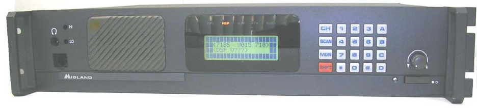
1) LCD Display
LCD display consists of 4 x 20 characters as shown.
Line 1 : Incoming RSSI with 10 steps
Line 2: Output power levels with 10 steps
Line 3: Left 4 letters show Channel Numbers. Middle 8 letters
show channel name (if not programmed, shows blank).
Right 4 letters show status of the radio.
1/ RX mode : M= Mix, both analog and digital can be received
D= Only digital can be received.
2/ TX mode: D=PTT digital transmission
A=PTT analog transmission
3/ Monitor mode: X= Monitor off
S= Selective squelch
4/ P-25 squelch: N= Normal squelch
S= Selective squelch
5/ Key lock mode: =Key lock
6/ Shift mode: Depressing the SHIFT KEY (back to normal
after 2 seconds)
Line 4 : Left 2 letters .show GROUP CALL, ALL CALL, INDIVIDUAL CALL.
Right 18 letters show GROUP NAME, INDIVIDUAL NUMBERS, ETC.
1 2 3 4 5 6 7 8 9 0 1 2 3 4 5 6 7 8 9 0
1
2
3
4
RX = = = = = = = = = =
TX = = = = = = = = = =
C001 Channel MDXN
GP 500
2) LED Display
BASE TECH III has 5 LED's, from the left ;
DIGI= LED on when receiving digital signal
REP= LED on when repeat mode. BASE TECH III can be programmed
SIMPLEX -SEMIDUPLEX - DUPLEX- REPEATER on a per channel basis
ALM= LED flashing on when an error on either TX or RX occurs
TX= LED on when in Transmit
BUSY= LED on when carrier is present
Preliminary Base Tech III Operating Manual
4
3) Key controls
a/ Key entry without SHIFT key
0-9 : channel numbers and individual call address (target address)
A: P-25 calls (Group call, All call, Individual call)
B: The beginning and the end of individual call number
C: No function
D= P-25 mode (analog or digital)
*= Cancel channel number, individual number
#= Ending channel number, individual number
CH= Channel number entry, depress CH, then 0-9 for channels
F(Scan)= No function
MON= monitor ON or OFF '
Rotary knob: Volume, Squelch, Back Light Dimmer level
b/ Key entry following to SHIFT key 0= P-25 test mode start
and finish
1=back light ON/OFF
2=Tx power Hi/LOW
3=No function
4=No function
5=No function
6=No function
7=lndicating channel data
8=Key lock ON/OFF
9=No function
A= No function
B= No function
C= No function
D= No function
*= Indicating P-25 data
#=No function
CH= Toggle Bar-Graph ON/OFF
F(scan)= No function
MON=P-25 squelch. normal or selective squelch

Preliminary Base Tech III Operating Manual
5
4) Programming
Base Tech III can be programmed through PC at anytime when RX mode. Programming is not
possible while Base Tech III in key entry.
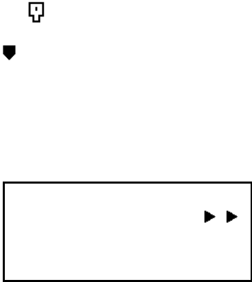
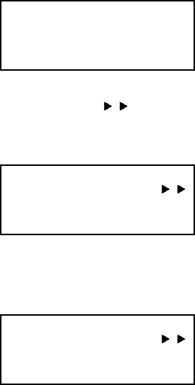
When programming is started, the LCD indicates as shown.
Figure-1 shows Data from radio to PC,
Figure-2 shows Data from PC to radio.
If the program software is not communicating properly, the radio will re-write again and again
(endless). When this happens, keep depressing SHIFT and switch on the radio. Then the radio will
recover.
Figure-3 shows display when SHIFT+ POWER switch on.
<Data Programming>
<71BS V100 710>
Data Output
Figure 1.
<Data Programming>
<71BS V100 710>
Data Input
Figure 2.
<Data Programming>
<71BS V100 710>
Figure 3.

Preliminary Base Tech III Operating Manual
6
5) Volume control
Push rotary knob, and then rotating the knob. Volume level varies from VOLO to VOL-34.
Figure 4 shows VOL-12 level
RX = = = = = = = = = =
TX = = = = = = = = = =
C001 Channel
GP VOL - 1 2
Figure 4.
6) Squelch control
Push rotary knob to select Squelch. Squelch level varies from SQL-l to SQL-l5.
Figure-5 shows SQL-9 level
RX = = = = = = = = = =
TX = = = = = = = = = =
C001 Channel
GP SQL - 9
Figure 5.
7) LCD backlight dimmer
Push rotary knob to select DIM. Dimmer level varies from DIM-O to DIM-15. DIM-0 is the most darkest.
Figure-6 shows DIM-5 level
RX = = = = = = = = = =
TX = = = = = = = = = =
C001 Channel
GP DIM - 5
Figure 6

Preliminary Base Tech III Operating Manual
7
8) Channel Selection
BASE TECH III has capability of up to 500 channels. Press CH, and then 0-9 key for channel
numbers Example:-1 CH-8
CH + 0 + 0 + 8
Example-2 CH-500
CH + 5 + 0 + 0
9) P-25 Squelch control
Press SHIFT then MON to choose P-25 squelch mode.
Normal SQ= If NAC is the same, then receiver will unmute
Selective SQ= If NAC and GROUP is the same, then receiver will unmute
If radio is called with the correct individual number, then radio will unmute.
Figure-7 shows Normal SQ,
Figure-8 shows Selective SQ
RX
TX
C001 Channel MDXN
GP Normal SQL
Figure 7.
RX
TX
C001 Channel MDXN
GP Selective SQL
Figure 8

Preliminary Base Tech III Operating Manual
8
10) P-25 PTT mode
Press D to select PTT mode.
When PTT= analog, PTT transmits analog
When PTT= digital, PTT transmits digital;
Figure-9 shows Analog
Figure-10 shows Digital
RX
TX
C001 Channel MAXN
GP PTT is Analog
Figure 9
RX
TX
C001 Channel MDXN
GP PTT is Digital
Figure 10

Preliminary Base Tech III Operating Manual
9
11) P-25 Calling selection
Press A to select GP= group call, AL= all call, ID= individual call
Figure-11 shows group call 500=TGID (talk group ID)
Figure-12 show all call, 65535=all call group TGID
Figure-13 shows individual call
RX
TX
C001 Channel MDXN
GP 500
Figure 11
RX
TX
C001 Channel MDXN
AL 65535
Figure 12.
RX
TX
C001 Channel MDXN
ID - - - - - - - - -
Figure13

Preliminary Base Tech III Operating Manual
10
12) Individual call (target call)
This function works only selected Individual call in Para-11
Press B, and enter 0-9 for individual numbers.
Press B or # to complete entry.
To clear, press * to erase the last entry.
Figure-14 shows to start entry, pressing B
Figure-15 shows to complete entry, 1 +2+3+4+5+B
RX
TX
C001 Channel MDXN
ID __
Figure 14.
RX
TX
C001 Channel MDXN
ID 1 2 3 4 5
Figure 15.
13) Group name
If GP is selected, TGID name is indicated (Max 8 characters)
Figure-16 shows POLICE for TGID name
RX
TX
C001 Channel MDXN
GP P O L I C E
Figure 16

Preliminary Base Tech III Operating Manual
11
14) Key lock
SHIFT+8 = Key lock. This symbol shows on LCD
However, PTT, MON and SHIFT key are not locked.
If you need to lock these 3 keys, then you may select in Programming software as DISABLE. If the
station is to be remotely controlled it is recommended to leave PTT enabled, Remote PTT will not
work when PTT is locked.
To release key lock, press SHIFT+ 8 again.
Figure-17 shows key locked
Figure-18 shows key unlocked
RX
TX
C001 Channel
GP Key Lock
Figure 17
RX
TX
C001 Channel
GP Key Unlock
Figure 18
15) Channel status data
Press SHIFT+7 shows the following modes, every 1.5 seconds to check modes when 7 is depressed.
1/ Rx width (narrow/wide/4khz)
2/ TX width (narrow/wide/4KHz)
3/ Base mode (Simplex/Semi-duplex/Duplex/Repeater)
4/ Rx CTCSS/DCS, CTCSS and DCS are used in Rx
5/ TX CTCSS/DCS, CTCSS and DCS are used in TX However, these functions must be enabled in
software at MISCELLANEOUS menu; INFORMATION DISPLAY-ENABLE
Figure-19 shows SHIFT+ 7 indicating narrow channel.
RX
TX
C001 Channel
RX Narrow Channel
Figure 19

Preliminary Base Tech III Operating Manual
12
16) P-25 Status data
Press SHIFT+* shows the following modes, every 1.5 seconds to move when * is depressed.
1/ Unit ID (source address)
2/ RX NAC
3/ TX-NAC
4/ TGID
However, these functions must be enabled in software at MISCELLANEOUS menu; INFORMATION
DISPLAY-ENABLE
Figure 20 shows SHIFT+* indicating Unit ID code
RX
TX
C001 Channel
Unit ID 1 1 9 3 0 4 6
Figure 20
17) Bar Graph/ Channel Display
Press SHIFT+CH to eliminate bar graph. In turn, current working frequencies are shown on LCD.
Press SHIFT + CH to toggle back
Figure-21 shows SHIFT+CH to indicate TX and RX frequencies.
RX 160.0125 MHz
TX 161.8500 MHz
C001 Channel
GP 500
Figure 21
Preliminary Base Tech III Operating Manual
13
18) LCD back light hold
By Default, back light illuminates for 5 seconds after any key press then goes out. Press SHIFT +1
for back light hold. Press SHIFT+ 1 again to be back normal. Figure-below shows back light turns
on.
RX
TX
C001 Channel
GP Light turn ON
19) Changing TX power
Press SHIFT+2 to select High and Low TX power. shows high power. If the radios are pre-
programmed Hi-Lo power with programming soft, SHIFT+2 overcomes this pre-program level.
Figure-below shows Hi power with SHIFT+2.
RX
TX
C001 Channel
GP 500
20) Caller ID
BASE TECH III indicates caller's Unit ID or Individual ID. However if the radio is programmed as
repeater mode, these caller's ID are not displayed. Figure-below shows caller's ID 12345.
RX
TX
C001 Channel
Call 0 0 1 2 3 4 5

Preliminary Base Tech III Operating Manual
14
21) Emergency call reception
In the 4th line of the LCD shows EMG when emergency received. LCD back light is
flashing and audible tone out from speaker. Figure-below shows Emergency caller's ID
98765.
RX
TX
C001 Channel
EMG 98765
22) Repeater mode
BASE TECH III repeats automatically when programmed as a repeater.
a) Rx mode = digital
Repeats only the same NAC code. If the NAC is $F7F, all incoming signals are repeated. .
Repeating shuts automatically after 0.0-9.9 seconds if no incoming signal is detected (time
programmable).
b) Rx mode = Mix
In addition with above conditions, radio repeats the correct CTCSS,
DCS are detected, or only the carrier as well.
Radio can not repeat analog and digital at the same time.
23) Remote control
BASE TECH III can be controlled by remotely. Keep the EXT/CH at low level, then switch ON, radio
works as remote mode. If you switch ON first, prior to the LOW level, no remote mode is activated.
To recover normal mode, EXT/CH set at HI. Please note the maximum channels through remote
control is up to 256 channels.
CHO - CH7 : all low ... CH-1
CHO - CH7 : all high........C H-256
Figure-below shows CH –1 in remote control mode. The 3rd line shows E001 instead of C001
(EXXX means remote, CXXX is Local Mode)
RX
TX
E001 Channel
GP 500

Preliminary Base Tech III Operating Manual
15
24) P-25 Test mode
Press SHIFT+ 0 to move test mode. The table for test mode are;
1/ Standard transmitter test pattern
2/ Standard transmitter symbol rate pattern
3/ Standard transmitter low deviation pattern
4/ Standard transmitter C4FM modulation fidelity pattern
5/ Standard tone test pattern
Press the PTT to transmit above patterns. To change patterns, press key 1-5.
Figure-23 shows test mode, LCD indicates from 1 to 5 alternatively.
Figure-24 show Symbol rate
Figure-25 shows Low deviation(CTCSS/DCS)
Figure-26 shows C4FM
Figure-27 shows Tone test
At Tone test, indicates Rx error bit rate in %
Figure-28 shows error rate 45%
Figure-29 shows back to 1 mode.
<P 25 Test Mode>
Test Pattern
C0001 Channel
Figure 23
<P 25 Test Mode>
Symbolic Rate
C0001 Channel
Figure 24
<P 25 Test Mode>
Low Deviation
C0001 Channel
Figure 25

Preliminary Base Tech III Operating Manual
16
<P 25 Test Mode>
C4FM modulation
C0001 Channel
Figure 26
<P 25 Test Mode>
Tone Test
C0001 Channel
Figure 27
<P 25 Test Mode>
Tone Test
C0001 Channel
Error Rate 45%
Figure 28
<P 25 Test Mode>
Test Pattern
C0001 Channel
Figure 29

Preliminary Base Tech III Operating Manual
17
25) Adjust mode
Ground the TP-2 on the analog logic board, and switch on the radio. Then the following parameters
are adjustable.
1/ RX AK2344 VR4... Rx 0dBm output level
2/ RX FX828 MOD-1... Deviation level at the repeater mode (analog)
3/ TX FX828 MOD-1... Deviation level (digital)
4/ TX FX828 MOD-2... Deviation level (analog)
Press A and B to adjust the level, and # key for changing mode.
Cycle power to radio to return to the normal mode.
Figure-30 shows adjust mode
Figure-31 shows RX MOD-1
Figure-32 shows TX MOD-1
Figure-33 shows TX MOD-2
<Adjust Mode>
RX AK2344 VR4
C0001 3 1 / 3 1
Figure 30
<Adjust Mode>
RX FX828 MOD1
C0001 3 1 / 3 1
Figure 31
<Adjust Mode>
TX FX828 MOD1
C0001 3 1 / 3 1
Figure 32
<Adjust Mode>
TX FX828 MOD2
C0001 3 1 / 3 1
Figure 33

Preliminary Base Tech III Operating Manual
18
26) Key test
Keep depressing C and switch on the radio, then radio comes to Key test mode.
Figure-34 shows key test mode
<Key Test>
Please Key - in
Figure 34
Then depress any key to test.
Figure-35 shows CH key depressed.
Figure-36 shows rotary switch turn clockwise
Figure-37 shows rotary switch turn counter-clockwise
<Key Test>
CH Key
Figure 35
<Key Test>
RTSW UP
Figure 36
<Key Test>
RTSW DWN
Figure 37

Preliminary Base Tech III Operating Manual
19
27) Displaying firmware version
Both firmware and DSP soft version are indicated on LCD after the radio switch on for 2
seconds.
Figure-38 shows when “no start message” is programmed
<71BS V100 710
<DSP V041>
Figure 38
Figure-39 shows start message “Your Messag Here” is programmed
Your Messag Here
Figure 39
28) Displaying serial number
Press D and switch on the radio, the serial number is indicated. (max 8 digits). Releasing D key, the
radio starts normally.
Figure-40 shows KY0000329 serial number
r
Serial KY000329
Figure 40

Preliminary Base Tech III Operating Manual
20
29) Displaying Program software version
Keep pressing A and turn on the radio, then programming soft version is indicated. Releasing A key
to start radio normally.
Figure-41 shows V-1.00 version
Set by p-kgprg 1.00
Figure 41
30) Data check
BASE TECH III has self diagnostic function. All data in EEROM is checked every time the radio
is switched on. If the data is not properly stored, radio automatically turns to programming mode
Figure-42 shows EROM error
EROM Data Error
Figure 42

Preliminary Base Tech III Operating Manual
21
31) Error Displays
Either RX PLL, TX PLL or PA power is defective, then ALM LED flashes on and indicates which unit
becomes faulty.
Figure-43 shows RX PLL error, Note this may be displayed in REM mode if the remote channel lines
are open or a channel is selected remotely that is not programmed. (EXXX will be displayed instead
of CXXX, where XXX is the channel number.)
Figure-44 shows TX PLL error
Figure-45 shows PA error
RX
TX
C001 Channel
RX PLL Error
Figure 43
RX
TX
C001 Channel
TX PLL Error
Figure 44
RX
TX
C001 Channel
PA Error
Figure 45
32) Firmware error detection
When the radio itself detects malfunction, the main CPU will restart automatically.
33) RS232 error detection
If the communications between PC and the radio have trouble, the following message are shown
on the LCD.
1/ Over run error
2/ Framing error
3/ Parity error
4/ Unknown command
5/ Data unmatched
6/ Send error
7/ Answer timeout
8/ Receive timeout

Preliminary Base Tech III Operating Manual
22
34) DSP error detection
When DSP does not work properly, the following message are shown
on the LCD. Please check DSP board is firmly connected, or replacing the DSP board.
Figure-46 shows DSP failure
Figure-47 shows DSP not ready
Figure-48 shows DSP serial error
RX
TX
C001 Channel
DSP Failure!
Figure 46
RX
TX
C001 Channel
DSP not ready
Figure 47
RX
TX
C001 Channel
DSP serial Err!
Figure 48