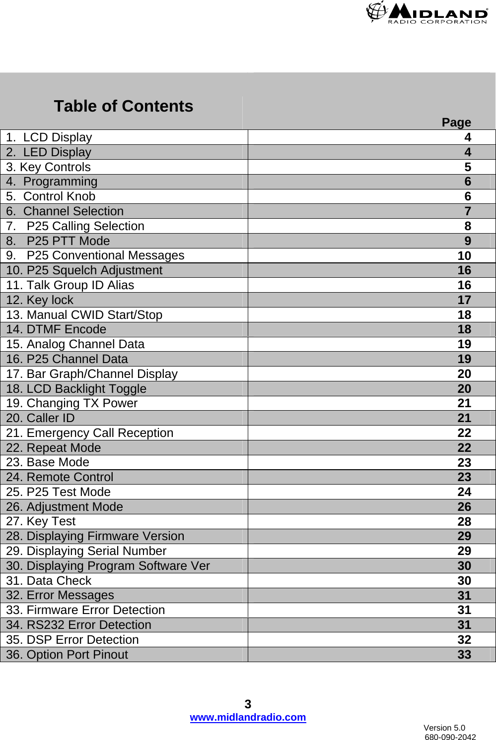
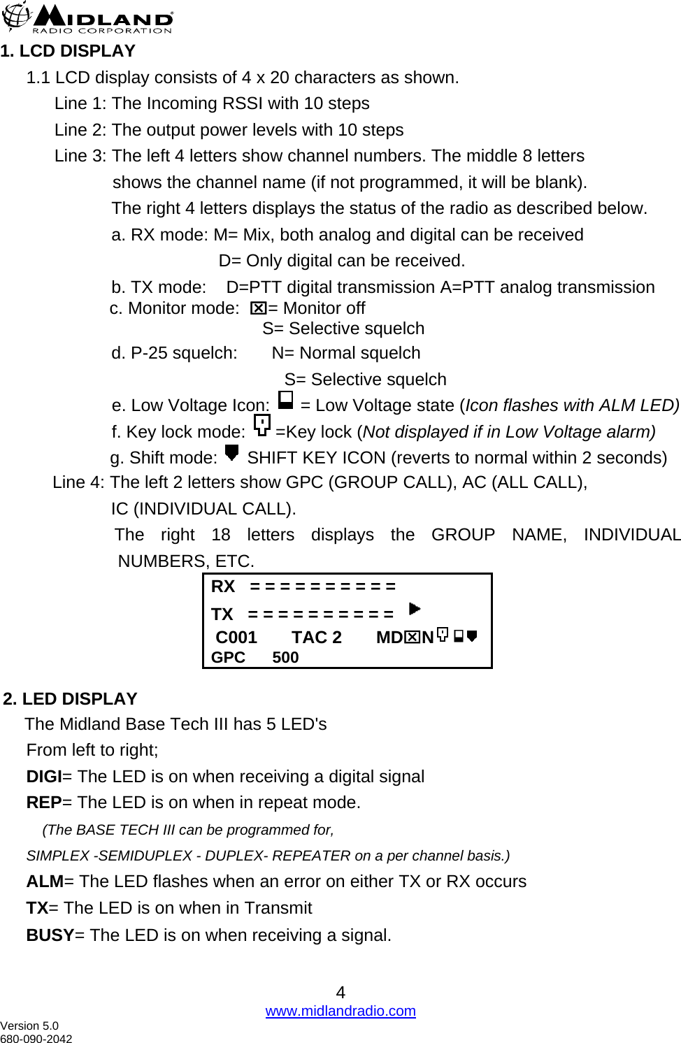
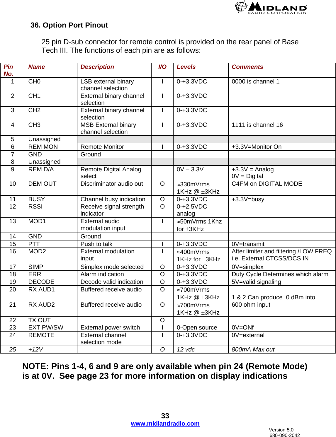
Midland Radio 917100R BASE STATION TRANSMITTER User Manual Base Tech III OPERATOR S MANUAL
Midland Radio Corporation BASE STATION TRANSMITTER Base Tech III OPERATOR S MANUAL
UserManual.wiki
>
Midland Radio
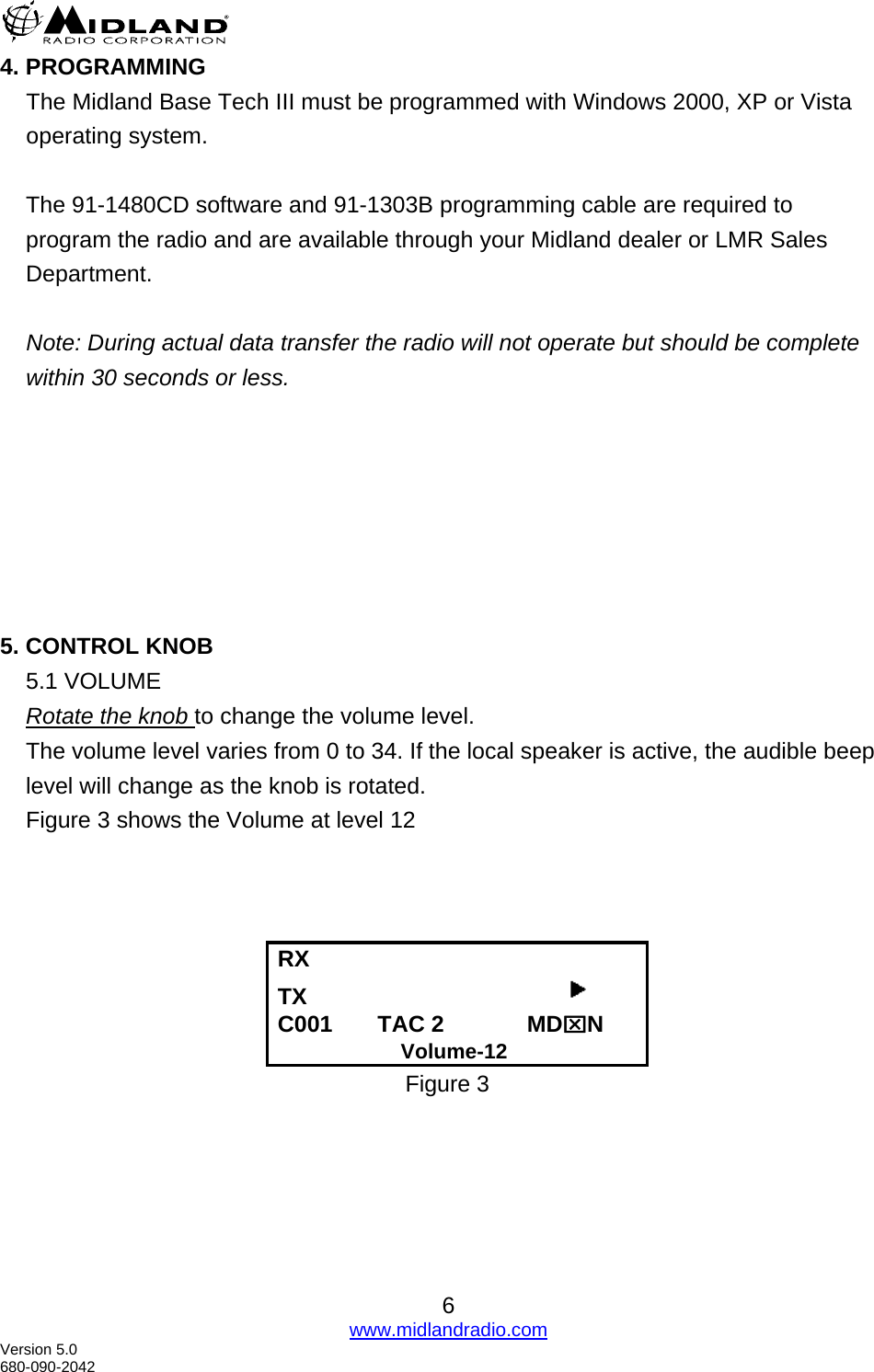
>
917100R User Manual
Users Manual
Navigation menu
Upload a User Manual
Namespaces
Wiki Guide
HTML
PDF
Info
Views
User Manual
Discussion / Help
Navigation