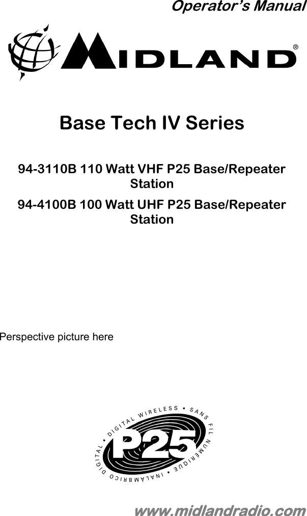
Midland Radio 943110B VHF BASE TECH IV TRANSCEIVER User Manual User s Guide
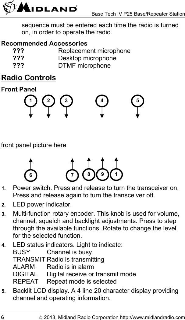
Midland Radio Corporation VHF BASE TECH IV TRANSCEIVER User s Guide
UserManual.wiki
>
Midland Radio
>
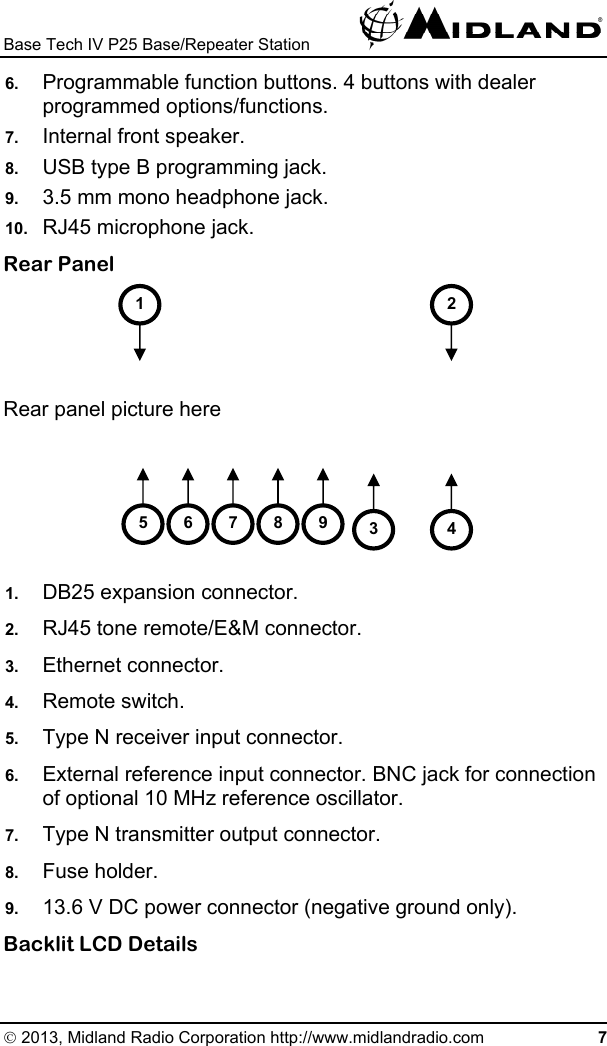
943110B User Manual
User Manual
Navigation menu
Upload a User Manual
Namespaces
Wiki Guide
HTML
PDF
Info
Views
User Manual
Discussion / Help
Navigation