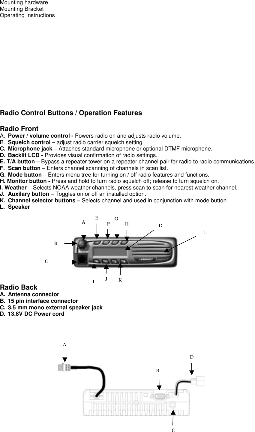
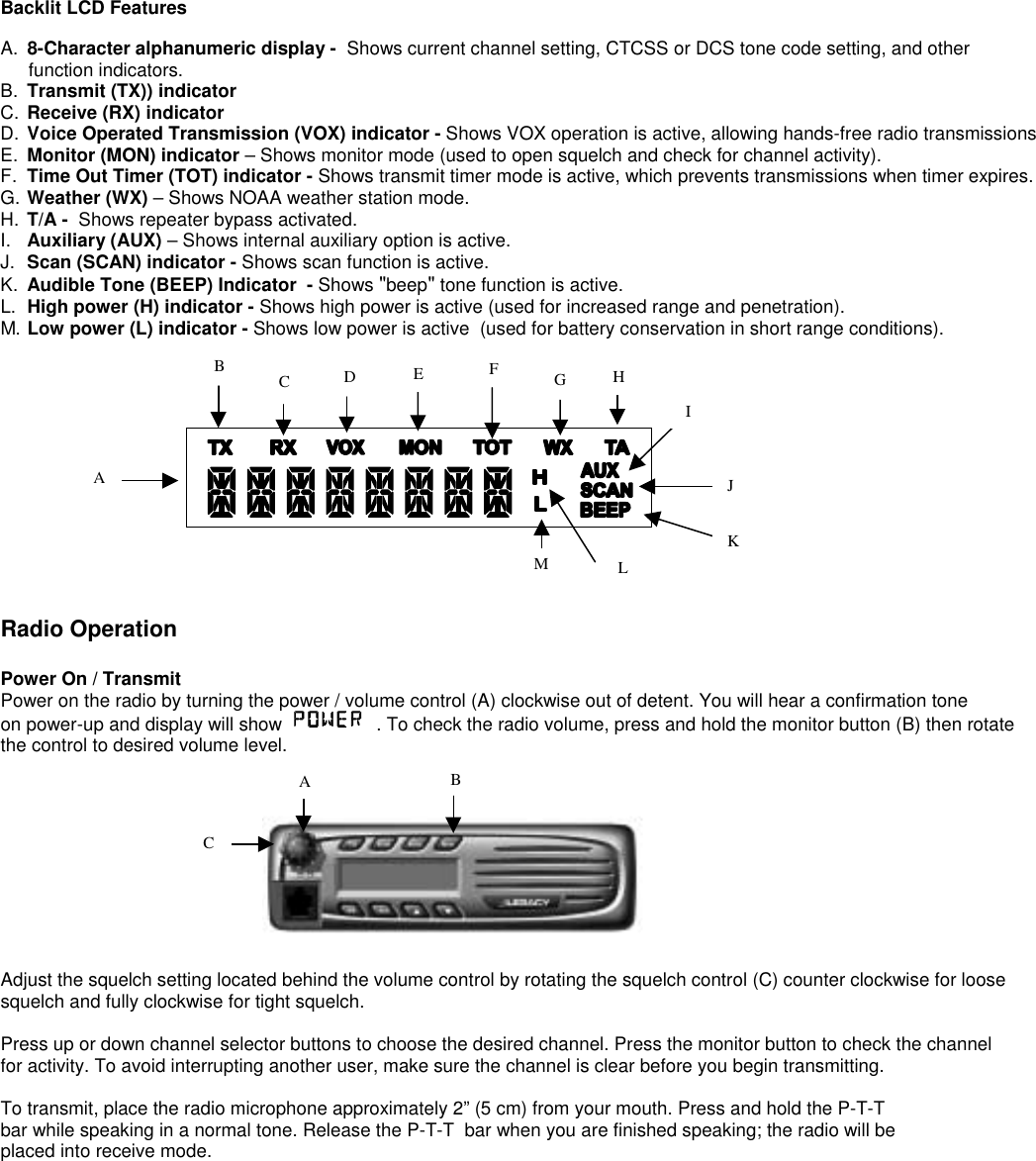
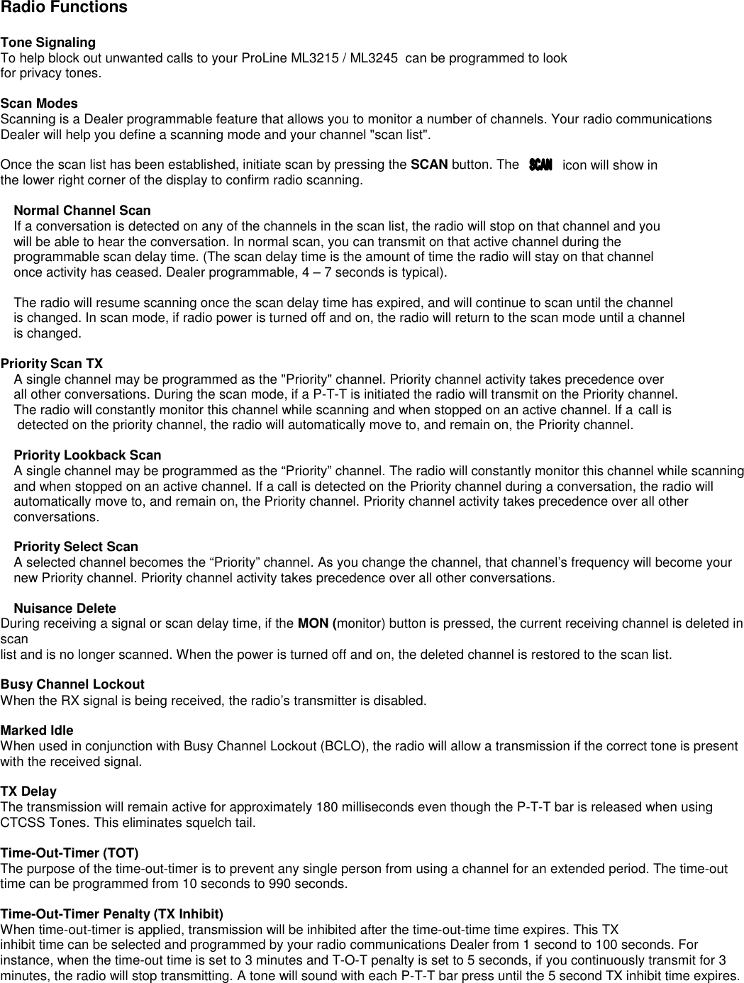
Midland Radio ML3215 32 Channel Mobile Radio User Manual PL5161 PL5164

Midland Radio Corporation 32 Channel Mobile Radio PL5161 PL5164

revised manual

ProLineSeries    ML3215 /ML3245Operating
Table of ContentsFCC RF Exposure Compliance Requirements - for Occupational Use Only........……… 1Safety Information.................................……………………………………………………….. 1About Topaz3...........................................……………………………………………………..  2About Your Legacy ProLine Radios.............…………………………………………………… 2Unpacking and Checking Equipment..........…………………………………………………… 2Radio Control Buttons / Operation Features..……………………………………………. ….. 3Radio Operation.......................................……………………………………………………… 4Power On /Transmit...............................………………………………………………………. 4Radio Functions.......................................……………………………………………………… 4ToneSignaling.........................……………………………………………………………………4Scan Modes........................................………………………………………………………….5 Normal ChannelScan..........................………………………………………………………… 5Priority Scan TX ............................……………………………………………………………… 5Priority Look Back Scan............…………………………………………………………………. 5Priority Select Scan............…………………………………………………………………….. 5Vacant Channel Scan............…………………………………………………………………,, 5Nuisance Delete....................................……………………………………………………. 5Busy Channel Lockout............................…………………………………………………… 5Marked Idle..........................................…………………………………………………….. 5TX Delay..............................................…………………………………………………….. 5Time-Out-Timer (T-O-T)............................. ………………………………………………. 5Time-Out-Timer Penalty (TX Inhibit)............………………………………………………. 5Two-Tone Decode.................................……………………………………………………. 5VOX (Voice Operated X-mit) ............……………………………………………………….. 5P/A Mode .................................…………………………………………………………. 5Mode Operation and Function Setup............…………………………………………………. 6Power On............………………………………………………………………………………… 6Channel Change............………………………………………………………………………… 6Transmit ............………………………………………………………………………………….. 6Channel Option View............………………………………………………………………….. 6Channel Option Settings Menu ...........…………………………………………………  6System Option Settings Menu ............……………………………………………………… 10Display Option Settings Menu ............………………………………………………………… 13P/A Option Settings Menu ............……………………………………………………………… 14ACC-733 DTMF Microphone Operation............………………………………………………... 14Licensing and Service Information..…………………………………………………………. 15FCC Licensing......................................…………………………………………………………. 15Service...............................................…………………………………………………………. 15Maintenance..........................................…………………………………………………………. 15Software Copyrights................................………………………………………………………… 16Topaz3 / Legacy Product Warranty.........…………………………………………………………….16
FCC RF Exposure Compliance Requirements -for Occupational Use OnlyThe Federal Communications Commission (FCC), with its actionin General Docket 93-62, November 7, 1997, has adopted asafety standard for human exposure to Radio Frequency (RF) electromagnetic energy emitted by FCC regulated equipment.Topaz3 / Maxon subscribes to the same safety standard for theuse of its products. Proper operation of this radio will result inuser exposure far below the Occupational Safety and Health Act (OSHA) and Federal Communications Commission limits.Antennas used for this transmitter must not exceed an antenna gain of 0dBd. The radio must be used in vehicle-mount config-urations with a maximum operating duty factor not exceeding 50%, in typical push-to-talk configurations. This radio is NOTapproved for use by the general population in an uncontrolled environment. This radio is restricted to occupational use, workrelated operations only where radio operator must have the knowledge to control the exposure conditions of its passengersand bystanders by maintaining the minimum separation distance of 47.7 inches (121 cm) between any persons and the antenna.Failure to observe these restrictions will result in exceeding the FCC RF exposure limits.CAUTION - DO NOT transmit for more than 50% of total radio use time (50% duty cycle). Transmitting more than 50% of thetime can cause FCC RF exposure compliance requirements to be exceeded. The radio is transmitting when the “TX” icon onthe radio display is illuminated. You can cause the radio to transmit by pressing the P-T-T button on the radio’s microphone.CAUTION - DO NOT operate the transmitter of  ML3215, ML3245 mobile radios when someone (bystanders) outside the vehicle is within 47.7 inches (121 cm) of the antenna.Antenna installation must be limited to the center of the roof-top of a vehicle where the passengers are below the metallicground plane (roof-top) to ensure compliance.NOTE: This radio operates in FCC regulated frequency bands.All radios must be licensed by the FCC before use. Because this radio contains a transmitter, Federal law prohibitsunauthorized use or adjustments of this radio.This device complies with Part 15 of the FCC Rules. Operation is subject to the condition that this device does not causeharmful interference.SafetyCAUTION -  DO NOT operate the transmitter of any radio unless all RF connectors are secure and any open connectors are properly terminated.CAUTION -  DO NOT operate the radio near electrical blasting  caps or in an explosive atmosphere.CAUTION -  All equipment must be properly grounded for safe  operation.WARNING -  DO NOT allow children to operate transmitter -  equipped radio equipment.WARNING -  All equipment should be serviced by a qualified technician.WARNING -  It is mandatory that radio installations in vehicles fueled by liquefied petroleum gas conform to the followingstandard: National Fire Protection Association Standard NFPA 58 applies to radio installations in vehicles fueledby liquefied petroleum (LP) gas with LP gas container in the  trunk or other sealed-off spacewithin the interior of the vehicle. This standard requires that:1.  Any space containing radio equipment shall be isolated by a seal from the space in which the LP gas container and itsfittings are located.2.  Remote (outside) filling connections shall be vented to the outside.
About Topaz3Topaz3 is the exclusive supplier of Maxon®, Legacy and TruTalk brand communication products.Our product line ranges from FCC licensed two-way radios suitable for Business and Industry (B&I) markets like farm,government, law enforcement, utility, etc. to consumer communications equipment for recreational and light-duty businessmarkets.Product offerings include a variety of UHF and VHF handheld and mobile radios, repeaters and RF link modules as well asGMRS (General Mobile Radio Service) radios, MURS (Multi User Radio Service) radios, Citizen’s Band radios and weathermonitors.Available accessory items include a variety of carrying cases, spare batteries, desktop and mobile chargers,ear bud speaker microphones and more for each radio model.For additional information on our product line, visit our website: www.topaz3.comAbout Your Legacy ProLine RadioThe Legacy ProLine models ML3215 (VHF) and ML3245 (UHF) are fully programmable, synthesized radios featuring:•  32 Channels of operation•  8-Character alphanumeric display•  2  or 45 Watts output power• Channel scan•  38 Standard and 11 non-standard CTCSS tones•  104 DCS Codes•  Approved to MIL-STD810F specifications• Scan channel delete•  Busy channel lockout• Programmable CTCSS / DCS tones and two-tone decode• Wide / narrow channel spacing• TX Inhibit• VOX operation• Public address mode• Nuisance Delete•  Die-cast aluminum frame, polycarbonate cabinetPlease read this manual thoroughly before operating the radio. Application of some functions described in thismanual are determined by the system you use. Your radio communications Dealer will program your radio for youto have the greatest number of functions possible relative to your needs.Should you have questions regarding the operation of this radio, consult your radio communications Dealer, or contactthe Topaz3 Customer Service Department: 1-800-821-7848, Ext. 499.Unpacking InformationCarefully unpack the radio and its accessories. Use the item list below to identify the components included in the productpackaging, to ensure that no items are discarded in the packing materials.Radio BodyMicrophone
Mounting hardwareMounting BracketOperating InstructionsRadio Control Buttons / Operation FeaturesRadio FrontA.  Power / volume control - Powers radio on and adjusts radio volume.B.  Squelch control – adjust radio carrier squelch setting.C. Microphone jack – Attaches standard microphone or optional DTMF microphone.D. Backlit LCD - Provides visual confirmation of radio settings.E. T/A button – Bypass a repeater tower on a repeater channel pair for radio to radio communications.F.  Scan button – Enters channel scanning of channels in scan list.G. Mode button – Enters menu tree for turning on / off radio features and functions.H. Monitor button - Press and hold to turn radio squelch off; release to turn squelch on.I. Weather – Selects NOAA weather channels, press scan to scan for nearest weather channel.J. Auxilary button – Toggles on or off an installed option.K. Channel selector buttons – Selects channel and used in conjunction with mode button.L. SpeakerRadio BackA. Antenna connectorB. 15 pin interface connectorC. 3.5 mm mono external speaker jackD. 13.8V DC Power cordAEFGDLHBCIJKABCD
Backlit LCD FeaturesA. 8-Character alphanumeric display -  Shows current channel setting, CTCSS or DCS tone code setting, and otherfunction indicators.B. Transmit (TX)) indicatorC.  Receive (RX) indicatorD.  Voice Operated Transmission (VOX) indicator - Shows VOX operation is active, allowing hands-free radio transmissionsE.  Monitor (MON) indicator – Shows monitor mode (used to open squelch and check for channel activity).F.  Time Out Timer (TOT) indicator - Shows transmit timer mode is active, which prevents transmissions when timer expires.G. Weather (WX) – Shows NOAA weather station mode.H.  T/A -  Shows repeater bypass activated.I.  Auxiliary (AUX) – Shows internal auxiliary option is active.J.  Scan (SCAN) indicator - Shows scan function is active.K.  Audible Tone (BEEP) Indicator  - Shows "beep" tone function is active.L.  High power (H) indicator - Shows high power is active (used for increased range and penetration).M. Low power (L) indicator - Shows low power is active  (used for battery conservation in short range conditions).Radio OperationPower On / TransmitPower on the radio by turning the power / volume control (A) clockwise out of detent. You will hear a confirmation toneon power-up and display will show    . To check the radio volume, press and hold the monitor button (B) then rotatethe control to desired volume level.Adjust the squelch setting located behind the volume control by rotating the squelch control (C) counter clockwise for loosesquelch and fully clockwise for tight squelch.Press up or down channel selector buttons to choose the desired channel. Press the monitor button to check the channelfor activity. To avoid interrupting another user, make sure the channel is clear before you begin transmitting.To transmit, place the radio microphone approximately 2” (5 cm) from your mouth. Press and hold the P-T-Tbar while speaking in a normal tone. Release the P-T-T  bar when you are finished speaking; the radio will beplaced into receive mode.FEDCBAMLHGKJICBA
Radio FunctionsTone SignalingTo help block out unwanted calls to your ProLine ML3215 / ML3245  can be programmed to lookfor privacy tones.Scan ModesScanning is a Dealer programmable feature that allows you to monitor a number of channels. Your radio communicationsDealer will help you define a scanning mode and your channel "scan list".Once the scan list has been established, initiate scan by pressing the SCAN button. The icon will show inthe lower right corner of the display to confirm radio scanning.Normal Channel ScanIf a conversation is detected on any of the channels in the scan list, the radio will stop on that channel and youwill be able to hear the conversation. In normal scan, you can transmit on that active channel during theprogrammable scan delay time. (The scan delay time is the amount of time the radio will stay on that channelonce activity has ceased. Dealer programmable, 4 – 7 seconds is typical).The radio will resume scanning once the scan delay time has expired, and will continue to scan until the channelis changed. In scan mode, if radio power is turned off and on, the radio will return to the scan mode until a channelis changed.Priority Scan TXA single channel may be programmed as the "Priority" channel. Priority channel activity takes precedence overall other conversations. During the scan mode, if a P-T-T is initiated the radio will transmit on the Priority channel.The radio will constantly monitor this channel while scanning and when stopped on an active channel. If a call is detected on the priority channel, the radio will automatically move to, and remain on, the Priority channel.Priority Lookback ScanA single channel may be programmed as the “Priority” channel. The radio will constantly monitor this channel while scanningand when stopped on an active channel. If a call is detected on the Priority channel during a conversation, the radio willautomatically move to, and remain on, the Priority channel. Priority channel activity takes precedence over all otherconversations.Priority Select ScanA selected channel becomes the “Priority” channel. As you change the channel, that channel’s frequency will become yournew Priority channel. Priority channel activity takes precedence over all other conversations.Nuisance DeleteDuring receiving a signal or scan delay time, if the MON (monitor) button is pressed, the current receiving channel is deleted inscanlist and is no longer scanned. When the power is turned off and on, the deleted channel is restored to the scan list.Busy Channel LockoutWhen the RX signal is being received, the radio’s transmitter is disabled.Marked IdleWhen used in conjunction with Busy Channel Lockout (BCLO), the radio will allow a transmission if the correct tone is presentwith the received signal.TX DelayThe transmission will remain active for approximately 180 milliseconds even though the P-T-T bar is released when usingCTCSS Tones. This eliminates squelch tail.Time-Out-Timer (TOT)The purpose of the time-out-timer is to prevent any single person from using a channel for an extended period. The time-outtime can be programmed from 10 seconds to 990 seconds.Time-Out-Timer Penalty (TX Inhibit)When time-out-timer is applied, transmission will be inhibited after the time-out-time time expires. This TXinhibit time can be selected and programmed by your radio communications Dealer from 1 second to 100 seconds. Forinstance, when the time-out time is set to 3 minutes and T-O-T penalty is set to 5 seconds, if you continuously transmit for 3minutes, the radio will stop transmitting. A tone will sound with each P-T-T bar press until the 5 second TX inhibit time expires.
Press the P-T-T bar after the TX inhibit time expires to resume transmitting.Two-Tone DecodeEach channel can be programmed with two-tone decode selections: Individual Call, Group Call and Super Group Call. Yourradio communications Dealer can program your radio(s) for this feature. To activate or reset the two-tone decode, press andhold the AUX  button for 3 seconds. After two-tone is decoded an alarm will sound if  two tone alarm is turned on.VOX (Voice Operated TX)Allows your radio to transmit with the sound of your voice for hands-free operation. Your radio has a VOX sensitivity leveladjustment for noisy or windy conditions. The VOX icon will be displayed when option is active.P/A ModeAllows your radio to become a public address system with an optional external speaker connected. In this mode onlymicrophone audio heard over the optional external speaker when the P-T-T bar is pressed.Mode Operation and Function Set UpDepending on how your Dealer has programmed your radio, you may be able to change certain modes and functions of yourradio. Consult with your radio communications Dealer regarding which functions are available with your radio.The following identifies display prompts for various radio functions. NOTE: All functions are activated or turned off by pressingthe MODE button. Use the up or down buttons to toggle through the choices available with each function. To exit, press theMODE or P-T-T bar on the microphone.Power OnPower on the radio by turning the power / volume control knob clockwise out of detent. The radio will perform aself-check, showing  in the display. Two beeps are sounded when the radio is ready to enter normaloperation mode. If power-on detects an error to data in the last memory, the  display will appear,and an error tone will beep.Channel ChangePress and release the up or down. Your display will change with each channel selection, and will vary depending on how yourDealer programmed each channel description. A press and hold of up or down will scroll trough the channels.TransmitPress the P-T-T bar to transmit on the microphone; release to receive. Both TX (transmit) and RX (receive) are indicated bydisplay icons. When the VOX option is set and activated by voice, the radio transmits; if voice input stops, the radio maintainsTX for around 2 seconds, then returns to receive mode.Channel Option ViewIn receiving mode, if the MON (monitor) button is pressed for more than 2 seconds, the RX tone option and the TX toneoption for each channel selected will display.This display example identifies:       Receive, CTCSS, Tone 1This display example identifies:Transmit, CTCSS, Tone 1Channel Option Settings MenuNOTE: These setting instructions are per-channel. You must repeat for all channels. To enter the Menu setting, press andrelease the MODE button during the receive or standby mode. In the menu setting, use the up or down buttons to scrollthrough the sub-menu settings. To enter a sub-menu, press the MODE button when the desired sub-menu appears on screen,then press the up or down buttons to scroll through the sub-menu selections. To activate or turn off a sub-menu setting, pressand release the MODE button. The radio will save the setting, and return to standby mode.If the P-T-T button is pressed, the radio returns to standby mode. If the MON (monitor) button is pressed, the radio will returnto the previously displayed Menu setting.The Channel Options Settings menu and sub-menus are detailed on the next few pagesPress up or down to the desired channel. Press the MODE button and then the up or down button until appears. Press and release the MODE button to select. Sub-menu settings include:  ,  ,
 ,  , and   .Scroll through the sub-menu settings with the up or down buttons. To enter a sub-menu, press the MODE button when thedesired sub-menu appears on screen. settings include:   You can toggle between these settings with the up or down buttons. When the desired setting appears on screen, press theMODE button. Under the RX Tone and TX tone settings,  your choices toggle between   ,   ,  ,and       (No Tone, Continuous Tone Coded Squelch System tones, Digitally Coded Squelch tones and Invert DigitallyCoded Squelch tones).If you choose the CTCSS tone setting, you will need to use the up or down buttons to select the desired tone code of49 available. If you choose CTCSS code 1, your display will read: If you choose CTCSS code 49, your display will read: When the desired CTCSS tone code appears on the display, select and set your choice by pressing the MODE button or theP-T-T. The radio will save your selection and return to standby mode.CTCSS Tone Signaling Frequency TableNo. Freq. No. Freq. No. Freq. No. Freq. No. Freq.01 67.0 11 97.4 21 136.5 31 192.8 41 171.302 71.9 12 100.0 22 141.3 32 203.5 42 177.303 74.4 13 103.5 23 146.2 33 210.7 43 183.504 77.0 14 107.2 24 151.4 34 218.1 44 189.905 79.7 15 110.9 25 156.7 35 225.7 45 196.606 82.5 16 114.8 26 162.2 36 233.6 46 199.507 85.4 17 118.8 27 167.9 37 241.8 47 206.508 88.5 18 123.0 28 173.8 38 250.3 48 229.109 91.5 19 127.3 29 179.9 39 69.3 49 254.110 94.8 20 131.8 30 186.2 40 159.8If you choose the DCS tone code setting, you will need to use the up or down buttons to select the desired tone code of 105available. If you choose DCS code 023, your display will read: If you choose DCS code 754, your display will read: When the desired DCS tone code appears on the display,  select and set your choice by pressing the MODE button or the P-T-T. The radio will save your selection and return to standby mode.DCS Tone Signaling Frequency TableDCSCode DCSCode DCSCode DCSCode DCSCode DCSCode DCSCode DCSCode DCSCode DCSCode DCSCode023 054 125 165 245 274 356 445 506 627 732025 065 131 172 246 306 364 446 516 631 734026 071 132 174 251 311 365 452 523 632 743031 072 134 205 252 315 371 454 526 654 754032 073 143 212 255 325 411 455 532 662036 074 145 223 261 331 412 462 546 664043 114 152 225 263 332 413 464 565 703047 115 155 226 265 343 423 465 606 712051 116 156 243 266 346 431 466 612 723053 122 162 244 271 351 432 503 624 731
If you choose the IDCS tone code setting, you will need to use the up or down buttons to select the desired tone code of 105available. If you choose IDCS code 023, your display will read: If you choose IDCS code 754, your display will read: When the desired IDCS tone code appears on the display,  select and set your choice by pressing the MODE button or the P-T-T. The radio will save your selection and return to standby mode.IDCS Tone Signaling Frequency TableIDCSCode IDCSCode IDCSCode IDCSCode IDCSCode IDCSCode IDCSCode IDCSCode IDCSCode IDCSCode IDCSCode754 654 526 454 371 315 252 205 134 072 031743 632 523 452 365 311 251 174 132 071 026734 631 516 446 364 306 246 172 131 065 025732 627 506 445 356 274 245 165 125 054 023731 624 503 432 351 271 244 162 122 053723 612 466 431 346 266 243 156 116 051712 606 465 423 343 265 226 155 115 047703 565 464 413 332 263 225 152 114 043664 546 462 412 331 261 223 145 074 036662 532 455 411 325 255 212 143 073 032To set the per-channel radio transmit output power, press and release the MODE button, then the up or down buttons untilappears. Press the MODE button to select. Scroll through the sub-menu settings with the up or down buttons, press theMODE button when   appears. Settings include:          You can toggle between these per-channel settings with the up or down buttons. When the desired setting appears on screen,press the MODE button to select. The radio will save your selection, and return to standby mode. The displaywill show an “H”  or an “L” to confirm High (45 Watt) or Low (2 Watt) output power setting for the current channel.To set the normal scan list on/off setting, press and release the MODE button then the up or down buttons until the  display appears. Press and release the MODE button again to select. Scroll through the sub-menu settings with the upor down buttons, press the MODE button when  appears on screen.appears. Settings include:          You can toggle between these settings with the up or down buttons. When the desired setting appears on screen, pressthe MODE button to select. The radio will save your On or Off selection for the current channel, and return to standby mode.NOTE: Your radio will only scan channels with the scan setting “On”.To set the Priority scan list on/off setting, press and release the MODE button then the up or down buttons until the
display appears. Press and release the MODE button again to select. Scroll through the sub-menu settings with the upor down buttons, press the MODE button when     appears on screen. Settings include: and    .You can toggle between these settings with the up or down buttons. When the desired setting appears on screen, press theMODE button to select. The radio will save your On or Off selection for the current channel, and return to standby mode.NOTE: This setting is linked to the Priority Scan sub-menu in the “System Option” menu, detailed following this section. “IfPriority Scan option of “System Option” menu is on, Priority scan works only when the channel selector is positioned to thechannel with “PSCAN ON” displayed.”To set the two-tone option, press the MODE button then the up or down buttons until the  display appears. Press andrelease the MODE button again to select. Scroll through the sub-menu settings with the up or down buttons, press the MODEbutton when   appears on screen. Settings include:          You can toggle between these settings with the up or down buttons. When the desired setting appears on screen, press theMODE button to select. Next, toggle between On and Off status settings which occur for each above sub-menu.Example:  ,  and                       .When the desired setting appears on screen, press the MODE button to select. The radio will save your On or Off selection forthe current channel and return to standby mode. NOTE: Individual, Group and Super Group frequencies and timing areprogrammed by your radio communications Dealer.For quick reference, the next few pages detail the Channel Options Menu, sub-menus and their settings. Mode Option Setting Each Channel SettingSystem Option SettingDisplay Option SettingChannel Option Setting ToneOption Rx ToneTx ToneNo ToneCTCSSDCSInvert DCS1 ~ 49023 ~ 754023 ~ 754No ToneCTCSSDCSInvert DCS1~49023~754023 ~ 754P/A mode Setting
System Option Settings MenuTo enter the System Option Setting Menu, press and release the MODE button during the receive or standby mode, then usethe up or down buttons until  appears. Select the above option with a press and release of the MODE button. (Beep Set, VOX (Voice Operated TX) Set, Time-Out-Timer Set, Penalty, Busy Channel Lockout Set, Marked Idle, Scan Set,Priority Scan, Transmit Delay, Power Save, Clear-To-Talk, Roger Beep, 2 tone alarm, Microphone Hook and AudioCompander). Details on sub-menu settings follow.You can toggle between these settings with the up or down buttons. When the desired setting appears on screen, press theMODE button to select. If you choose the Beep Set setting, you will need to use the up or down buttons to choose or  . When the desired setting appears on screen, press the MODE button to select. The radio willsave your On or Off selection and return to standby mode.If you choose the VOX Set setting, you will also need to choose between On or Off selections, by using the up or downbuttons to choose, and the MODE button to select. If you choose On, you will need to choose a VOX level setting, whichincludes: ,   or  . You can toggle between these VOX sensitivity level settings with theup or down buttons. When the desired setting appears on screen, press the MODE button. The radio will save your selectionand return to standby mode.If you choose the Time-Out-Timer setting, your choices include:  or   . Toggle betweenthe settings with the up or down buttons. When the desired setting appears on screen, press the MODE button. If you choose“On”, you will need to choose the duration of the Time-Out-Timer setting, from 10 seconds to 990 seconds. Use the up ordown buttons to toggle, until the desired number of seconds appears on the display. Use the MODE button to select. The radiowill save your selection and return to standby mode. Example of display: NOTE: In the Time-Out-Timer sub-menu, if “Off” is selected by pressing the MODE button, the TOT function will be disabled,and the radio will return to standby mode.If you choose the Time-Out-Timer Penalty setting, your  choices include Penalty On or Off. Toggle between the settings withthe up or down buttons. When the desired setting appears on screen, press the MODE button. If you choose “On”, you willneed to choose the duration of the Penalty setting, from 1 second to 100 seconds. Use the up or down buttons to toggle, thenthe MODE button to select  the desired amount of time. The radio will save your selection and return to standby mode.Example of display: .NOTE: In the Time-Out-Timer Penalty sub-menu, if “Off” is selected by pressing the MODE button, the TOT Penalty functionwill be disabled, and the radio will return to standby mode.NOTE: If the radio transmits in excess of the set time, it will beep an error tone and the radio will receive a signal, but will NOTtransmit during the penalty time.Tx Output Power High/LowNormal Scan ListPriority Scan List2-Tone OptionPower High/LowNormal Scan On/OffPriority Scan On/OffIndividual ToneGroup ToneSuper Group ToneOn/OffOn/OffOn/Off
If you choose the Busy Channel Lockout setting, your choices include:   or     . Togglebetween the settings with the up or down buttons. When the desired setting appears on screen, press the MODE button. Yourradio will save your On or Off selection and return to standby mode.NOTE: If you select “On”, and the channel is busy, it will inhibit transmission.If you choose the Marked Idle setting, your choices include On or Off. Toggle between the settings with the up or downbuttons. When the desired setting appears on screen, press the MODE button to select. The radio will save your selection andreturn to standby mode.Example of display:  .NOTE: If the channel is set by Busy Channel Lockout, and transmit is inhibited, Marked Idle allows a transmission when yourCTCSS or DCS tone signal is received.If you choose the Scan Set setting,  your choices include:  ,  ,      and    . (Scan Mode, Scan Speed, Scan Delay and Lookback). You can toggle between these settings with the up ordown buttons. When the desired setting appears on screen, press the MODE button to select. If you select        , your choices will include:   ,   ,     and   . (Normal Scan Transmit, PriorityScan Transmit,  Priority Select Scan and Priority Only TX Scan). You can toggle between these settings with the up or downbuttons. When the desired setting appears on screen, press the MODE button to select. The radio will save your selection, andreturn to standby mode.If you select  the Scan Speed setting, you will need to choose the scan speed time, from 50 milliseconds to 500 milliseconds.Use the up or down buttons to select the desired speed, then the MODE button to select. The radio will save your selectionand return to standby mode. Example of display:  .NOTE: Scan speed time is the amount of time that scan stays on a channel (when there is no signal) before moving to thenext channel on the scan list.If you select the Scan Delay setting, you will need to choose the scan delay time, from 1 seconds to 30 seconds. Use the upor down buttons to select the desired time, then the MODE button to select. The radio will save your selection and return tostandby mode. Example of display:  .NOTE: Scan delay time is the standby time to remain on the channel after the receiving signal stops or after transmitting.If you select the Lookback setting, you will need to choose the desired lookback frequency time, from 1 second to 10seconds. Use the up or down buttons to select the desired time, then the MODE button to select. The radio will save yourselection and return to standby mode. Example of display:   .NOTE: In Priority Scan mode, Lookback time is the interval time to check the Priority Channel when the radio receives a signalon a non-priority channel.If you choose the Priority Scan setting, your choices include Priority Scan On or Off settings. You can toggle between thesesettings with the up or down buttons. When the desired setting appears on the display, press the MODE button to select. If youchoose the On setting, use the up or down buttons to select your desired Priority Scan channel, then the MODE button toselect. The radio will save your On or Off setting, and return to standby mode.Example of display:  .NOTE: In the Priority Scan setting mode, if the MODE or P-T-T buttons are pressed, Priority Scan will be disabledand the radio will return to standby mode.If you choose the TX Delay setting, your choices include On or Off settings. You can toggle between these settings with theup or down buttons. When the desired setting appears on the display, press the MODE button to select. The radio will saveyour selection and return to standby mode. Example of display: .NOTE: The TX Delay setting is used to remove the squelch tail from the receiving radio by creating a CTCSS turn-off(no tone) for 180 milliseconds after TX is completed.
If you choose the Clear To Talk setting, your choices include On or Off settings. You can toggle between these settings withthe up or down buttons. When the desired setting appears on the display, press the MODE buttonto select. The radio will save your selection and return to standby mode. Example of display:   .NOTE: If you select On, the radio issues a beep tone when pressing the P-T-T button, letting you know that speaking maybegin.If you choose the Roger Beep setting, your choices include On or Off settings. You can toggle between these settings withthe up or down buttons. When the desired setting appears on the display,  press the MODE button to select. The radio willsave your selection and return to standby mode.An example of the Roger Beep display:   .NOTE: If you select On, the radio issues a beep tone after TX is completed to confirm the transmission has finished.If you choose the 2 Tone Alarm setting, your choices include On or Off settings. You can toggle between these settings withthe up or down buttons. When the desired setting appears on the display, press the MODE button to select. The radio will saveyour selection and return to standby mode. An example of the 2 Tone Alarm display:  .NOTE: If you select On, the radio issues an alarm tone after a  2 tone signal is decoded and RX carrier is no longer present ifa call is received during the alarm the alarm will stop until the call is gone. Once the RX signal is no longer present the alarmwill continue until the 2 tone decode is reset by pressing the AUX button for 3 seconds.If you choose the Microphone Hook setting, your choices include On or Off settings. You can toggle between these settingswith the up or down buttons. When the desired setting appears on the display,  press the MODE button to select. The radio willsave your selection and return to standby mode.An example of the Microphone Hook display:  .NOTE: If you select On, the Microphone hub will not require ground to activate privacy tones.If you choose the Microphone Hook setting Off, the Hook Scan setting will appear, your choices include On or Off settings.You can toggle between these settings with the up or down buttons. When the desired setting appears on the display,  pressthe MODE button to select. The radio will save your selection and return to standby mode. An example of the Hook Scan display:  .NOTE: If you select Microphone Hook setting Off, the Microphone hub will require ground to activate privacy tones ifmicrophone hub is removed from ground privacy tones are defeated and the radio will operate in carrier squelch mode. If youselect Hook scan On, your radio will continue to scan with the microphone hub not grounded in carrier squelch mode.If you choose the Audio Compander setting, your choices include On or Off settings. You can toggle between these settingswith the up or down buttons. When the desired setting appears on the display,  press the MODE button to select. The radio willsave your selection and return to standby mode.An example of the Audio Compander display:  .NOTE: If you select On the audio quality between wide and narrow band channels will be the same.For quick reference, the next few pages detail the System Option Menu, sub-menus and their settings.System Option SettingBeep Tone Beep On/OffVOX Option VOX On/OffVOX Sensitivity Level 1 ~ Level 3TOT On 1 ~ 990 sec
Display Option Settings MenuWith the radio powered on, select the desired channel. Press the MODE button and then the up or down buttons untilappears. Press and release the MODE button to select. Sub-menu settings include:    Time Out TimerTOT OffTOT Penalty Penalty OnPenalty Off1 ~ 100 secBusy Lock Busy Lock On/OffMarked Idle Marked Idle On/OffScan Set Scan Mode Normal Scan TxPriority Scan TxPriority Select ScanPriority Only TxScan Speed TimeScan Delay TimeLook Back TimePriority ScanTx DelayClear To TalkRoger Beep50 ~ 500 msec1 ~ 30 sec1 ~ 10 secOnOffPriority Channel 1 ~ 16On/OffOn/OffOn/Off2-Tone Alarm Set On/OffMicrophone Hook OffOnHook Off Scan OffOnAudio CompanderOn/Off
                You can toggle between these settings with the up or down buttons. When the desired setting appears on screen, press theMODE button to select. If you select   , your choices will include:   ,  and (Name, Channel Number and Frequency). You can toggle between these settings with the up or down buttons. When thedesired setting appears on the display, press the MODE button to view the current information for that setting.Example of Name display:  .NOTE: The Name, Channel Number and Frequency settings are display-only settings. You can not change them within thesescreens.If you select the Slide Setting, your choices include Slide On or Slide Off. Toggle between the settings with the up or downbuttons. When the desired setting appears on screen, press the MODE button. Your radio will save your On or Off selectionand return to standby mode. NOTE: If Slide Setting is On, and the radio is in standby for more than 1 minute, a slide messagepre-programmed by your Dealer will scroll on screen.P/A Option Settings MenuWith the radio powered on press the MODE button and then the up or down buttons until  appears. Press andrelease the MODE button to select. To turn P/A mode off press the MODE button.   Example of P/A display: ACC-733 DTMF Microphone OperationThe ACC-733 can be used for telephone interconnect or other DTMF applications. Consult your Dealer for other applicationpossibilities. The ACC-733 can be operated in an auto dial mode or manually operated and is back lighted for low light conditions.A telephone ringer will be heard when a telephone connection has been established or for an incoming call.Auto Dial OperationUp to 16 digits can be dialed when using auto dial. Follow these steps to place a call using auto dial.A.  Enter the desired number by pressing and releasing 0 –9, * or # keys. The dialed numbers will appear in your radiodisplay. # will be indicated as F in your display. Note: The # key is normally used to end, or hang up, an interconnectsystem. Consult your Dealer for exact system operation. The * key will be indicated as E.Display Option Setting Channel Display Format Name Character DisplayChannel No. DisplayFrequency DisplaySlide Set Slide OnSlide OffBack Light Set Light OnLight Off
B.  Press the SND key to send the dialed number.C.   When the called party answers, press the P-T-T of the microphone to answer. Release the P-T-T to listen for a response.D.  When the conversation has ended Press and hold the P-T-T of the microphone press and hold the # key for 1 or 2seconds to end the call. Release the P-T-T when the call has ended.Manual Dial OperationA.  Press and hold the P-T-T of the microphone and enter the desired number by pressing and releasing 0 –9, * or # keys.The dialed numbers will appear in your radio display. # will be indicated as F in your display.  Note: The # key is normallyused to end, or hang up, an interconnect system. Consult your Dealer for exact system operation. The * key will beindicated as E.B.  When dialing is complete release the P-T-T and wait for the called party to answer.C.   When the called party answers, press the P-T-T of the microphone to answer. Release the P-T-T to listen for a response.D.  When the conversation has ended Press and hold the P-T-T of the microphone press and hold the # key for 1 or 2seconds to end the call. Release the P-T-T when the call has ended.To Store a Number in MemoryA.  Dial the desired number. Entered number will show in the radio display.B.  Press and release the STR key.C.  Press and release any number 0 – 9, * and # to store the number.To Recall a Stored number from MemoryA.  Press and release the RCL key.B.  Press and release the number key from which a number has been stored.C.  Press SND to dial the recalled number.If a number has been accidentally recalled repeat steps A. and B. until the proper number has been recalled.Clearing a Stored NumberA.  Press and release the RCL key.B.  Press and release the number key from which a number has been stored. The stored number will show in the radiodisplay.C.  Press and hold the CLR key to remove the stored number. A new number can now be entered and stored in that location.Clearing a Dialed NumberWhen a number has been accidentally entered during auto dial a press and release of the CLR key will delete an individualnumber. A press and hold of the CLR key will clear the entire dialed number.Licensing and Service InformationFCC LicensingThe Federal Communications Commission requires the operator of this radio be properly licensed under the applicable Partand/or Parts of the FCC Rules and Regulations.Consult your radio communications Dealer or contact the nearest FCC field office for information about obtaining a license.ServiceDo not tamper with internal adjustments. Damage to the equipment and/or improper operation may result. Thereare no serviceable components inside the radio.It is recommended that you return your radio to a qualified radio communications Dealer for any service or repairs.MaintenanceYour Legacy radio is designed to be maintenance free. To keep it in good working condition:
• Clean external surfaces with a clean cloth dampened in a solution of dishwasher detergent diluted in water. Apply thesolution sparingly to avoid any moisture leaking into cracks and crevices. DO NOT submerge the radio. Use a non-metallic brush, if necessary, to dislodge stubborn particles. Dry the surface thoroughly with a soft, lint free cloth.• DO NOT use solvents or spirits for cleaning – they may permanently damage the housing.Software Copyrights, Warranty StatementSoftware Copyrights The Topaz3 / Legacy products described in these operating instructions may include copyrighted Topaz3 / Legacy softwareprograms stored in semi-conductor memories or other media. Laws in the United States and other countries preserve forTopaz3 / Legacy certain exclusive rights for copyrighted software programs, including the exclusive right to copy or reproducein any form the copyrighted software program.Accordingly, the copyrighted Topaz3 / Legacy software programs contained in the Topaz3 / Legacy product(s) described inthis operating instruction manual may not be copied or reproduced without the express written permission of Topaz3, LLC.Furthermore, the purchase of Topaz3 / Legacy products shall not be deemed to grant either directly or by implication,estoppel, or otherwise, any license under the copyrights, patents or patent applications of Topaz3, LLC, except for normal non-exclusive, royalty-free license to use that arises by operation of law in the sale of a product.Topaz3 / Legacy Product WarrantyTopaz3, LLC (hereinafter, “Topaz3”) warrants that the Products and included accessories sold herein will be free from defectsin workmanship or materials under normal use and service for a period of two (2) years (one year for accessories) from thedate of purchase by the original end user, provided that the buyer has complied with the requirements stated herein. Thiswarranty is offered to the initial end user and is not assignable or transferable. Topaz3 is not responsible for any ancillaryequipment which is attached to or used in conjunction with Topaz3 / Legacy products.If the Product fails to function under normal use because of manufacturing defect(s) or workmanship during the two (2) yearsperiod following the date of purchase, it will be replaced or repaired at Topaz3's option at no charge when returned to theplace of purchase. The defective unit must be accompanied by proof of the date of purchase in the form of a sales receipt.The sole obligation of Topaz3 hereunder shall be to replace or repair the Product covered in this Warranty. Replacement, atTopaz3's option, may include a similar or higher-featured product. Repair may include the replacement of parts or boards withfunctionally equivalent reconditioned or new parts or boards. Replaced parts, accessories, batteries, or boards are warrantedfor the balance of the original time period. All replaced parts, accessories, batteries or boards become the property of Topaz3.Topaz3 shall have no obligation to make repairs or to cause replacement required through normal wear and tear ornecessitated in whole or in part by catastrophe, fault or negligence of the user, improper or unauthorized alterations or repairsto the Product, use of the Product in a manner for which it was not designed, or by causes external to the Product. Thiswarranty is void if the serial number is altered, defaced or removed.The user is responsible for the payment of any charges or expenses incurred for the removal of the defective product from thevehicle or site of its use, for the transportation of the product to the place of repair, for the return of the repaired / replacedproduct to the site of its use and for the reinstallation of the product.THE EXPRESS WARRANTIES CONTAINED HEREIN ARE IN LIEU OF ALL OTHER WARRANTIES, EITHER EXPRESSEDOR IMPLIED OR STATUTORY, INCLUDING, WITHOUT LIMITATION, ANY WARRANTY OF MERCHANTABILITY ORFITNESS FOR A PARTICULAR PURPOSE.
FOR ANY PRODUCT WHICH DOES NOT COMPLY WITH THE WARRANTY SPECIFIED, THE SOLE REMEDY WILL BEREPAIR OR REPLACEMENT. IN NO EVENT WILL TOPAZ3 BE LIABLE TO THE BUYER OR ITS CUSTOMERS FOR ANYDAMAGES, INCLUDING ANY SPECIAL, INCIDENTAL, INDIRECT OR CONSEQUENTIAL DAMAGES,OR FOR THE LOSS OF PROFIT, REVENUE OR DATA ARISING OUT OF THE USE OF OR THE INABILITY TO USE THEPRODUCT.This warranty is void for sales and deliveries outside of the U. S. A.Topaz3, LLC10828 NW Air World DriveKansas City, Missouri  64153www.topaz3.comToll free: 800-821-7848Phone: 816-891-6320 • Fax: 816-891-8815Printed in KoreaP/N: 680-090-xxxx

Navigation menu