Midland Radio MURS22 MURS-22 User Manual 2001083 MURS 22 CertificationReport
Midland Radio Corporation MURS-22 2001083 MURS 22 CertificationReport
UserManual.wiki
>
Midland Radio
>
MURS22 User Manual
Manual
Navigation menu
Upload a User Manual
Namespaces
Wiki Guide
HTML
PDF
Info
Views
User Manual
Discussion / Help
Navigation

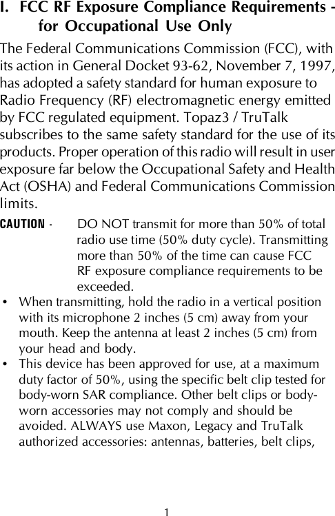

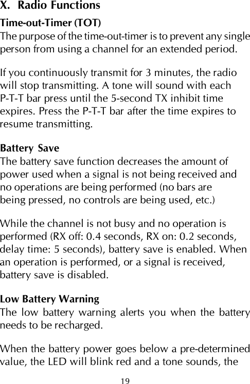
![VIII. CTCSS Tone Setup, continued10. Repeat steps 3 - 9 to set up the other channel.Example of setting up a channel with CTCSS toneno. 01: After entering CTCSS setup mode, press andhold the P-T-T bar until a 1-second tone sounds. Toselect 0 for the 10’s digit, hold the bar for 2-3 seconds.Wait for 2 seconds. A 1-second tone will sound toconfirm that “0” has been selected. Press the P-T-T bar1 time to select “1” for the 1’s digit. A beep soundswhen you press the P-T-T switch. Wait for 2 seconds.A short beep will sound to confirm that 1 has beenselected. Press the monitor bar. The LED will showgreen and blink twice. Press the monitor bar again.A 1-second tone will sound for the “0”, there will bea short pause, and then a short beep will sound forthe “1” to confirm that 01 has been selected.IX. Channel Setting ConfirmationFrequency ConfirmationYou can confirm the channel settings of your radioby following these steps:1. Select the channel you want to confirm.2. Press and hold the P-T-T bar, then turn the powerON. The beep pattern will sound. [i.e.- If frequency3 (151.9400) is set up on the channel, 3 short beepswill sound.]3. Repeat steps 1 - 2 to confirm the frequency of theother channel.17](https://usermanual.wiki/Midland-Radio/MURS22/User-Guide-153224-Page-23.png)
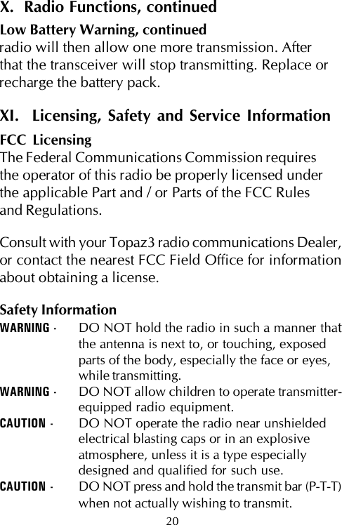
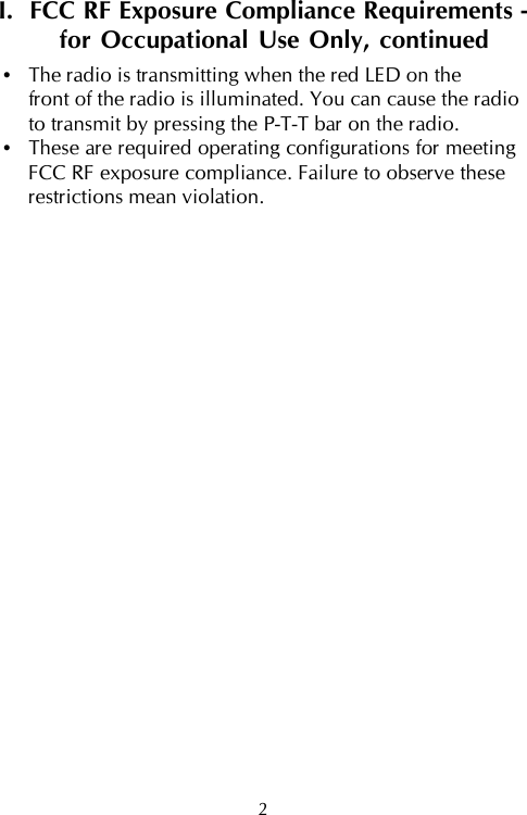
![18IX. Channel Setting Confirmation, continuedCTCSS Tone ConfirmationNOTE: There will be a short pause between theconfirmation of the 10’s digit and the confirmationof the 1’s digit.1. Select the channel you want to confirm.2. Press and hold the monitor bar, then turn the powerON. The beep pattern will sound. [i.e – If CTCSStone 01 is set up on the channel, a 1-second tonewill sound (0), there will be a short pause, andthen a short beep will sound (1)].3. Repeat steps 1 - 2 to confirm the CTCSS tone of theother channel.Confirmation Beep SettingsNumber Beep Pattern Number Beep Pattern0 1-second tone 5 five beeps1 single beep 6 long then short beep2 two beeps 7 long then 2 short beeps3 three beeps 8 long then 3 short beeps4 four beeps 9 long then 4 short beepsFactory Default Channel Setting - Model MURS-22Channel 1 154.5700 MHz Code no. 00 (OFF)Channel 2 154.6000 MHz Code no. 00 (OFF)](https://usermanual.wiki/Midland-Radio/MURS22/User-Guide-153224-Page-24.png)