Midland Radio MXT105 MOBILE GMRS TRANSCEIVER User Manual MXT105 Owner s manual indd
Midland Radio Corporation MOBILE GMRS TRANSCEIVER MXT105 Owner s manual indd
Owners Manual
MXT105 MicroMobile

Page 2 midlandusa.com
Model MXT105
Table of Contents
WELCOME TO THE WORLD OF MIDLAND RADIO
FEATURES
FCC NOTICE
Exposure To Radio Frequency Energy
INSTALLING YOUR RADIO
Preparation for Installation
Installing the Mounting Bracket
Installing the Antenna
Electrical and Rear Panel Connections
Connecting the Microphone
Using an External Speaker
CONTROLS AND INDICATORS
Operating Controls
LCD Display
Rear Panel Connections
OPERATING YOUR RADIO
About Range
Power On/Off
Selecting the Active Channel
Transmitting and Receiving a Call
UTILITY FUNCTIONS
Flipping the Display
Locking the Keypad
Adjusting the Display Illumination
Using Monitor Mode
NOAA Wx Radio Scan
Scanning for Active Channels
MENU” MODE FUNCTIONS
MXT105 “Menu” Mode Quick Reference Chart
Selecting a Privacy Code
Adjusting Squelch Sensitivity
Silent Operation
Selecting the Transmit (TX) Power Level
RESTORING THE DEFAULT SETTINGS
CARE AND MAINTENANCE
TROUBLESHOOTING GUIDE
SPECIFICATIONS
GMRS Frequency Chart
Wx Band Chart
CTCSS Privacy Codes Frequency Chart
DCS Privacy Codes Chart
LIMITED WARRANTY (United States and Canada)
2
3
3
4
4
5
5
6
7
8
8
9
9
9
10
10
11
11
12
12
12
13
13
13
14
14
15
16
17
17
17
19
19
20
20
21
21
22
22
22
23
23
26

Page 3
midlandusa.com
Model MXT105
WELCOME TO THE WORLD OF MIDLAND RADIO
Congratulations on your purchase of a high quality MIDLAND product.Your
MXT105 2-way radio represents state-of-the-art high tech engineering.
Designed for General Mobile radio Service (GMRS) operation, this
compact package is big on performance. It is a quality piece of electronic
equipment, skillfully constructed with the nest components. The circuitry
is all solid-state and mounted on a rugged printed circuit board. Your
MXT105 radio is designed for reliable and trouble-free performance for
years to come.
FEATURES
– 15 GMRS Channels
– 10 NOAA Weather Channels
– 142 Privacy Codes (38 CTCSS / 104 DCS)
– Monitor Function
– Keypad Lock
– Power HI/LO Settings
– External Speaker Jack
IMPORTANT!
Changes or modications to this unit not expressly approved by
MIDLAND RADIO CORPORATION could void your right to operate this
unit. Your radio is set up to transmit a regulated signal on an assigned
frequency. It is against the law to alter or adjust the settings inside the
COMMUNICATOR to exceed those limitations. Any adjustment to your
radio must be made by qualied technicians.

Page 4 midlandusa.com
Model MXT105
FCC NOTICE
The MXT105 operates on GMRS (General Mobile Radio Service)
frequencies, which require a Federal Communications Commission (FCC)
license. You must be licensed prior to operating on channels 1-7 or 15-22,
which comprise the GMRS channels of the MXT105. Serious penalties
may result from unlicensed use of GMRS channels, in violation of FCC
rules, as stipulated in the Communications Act’s Sections 501 and 502
(amended). You will be issued a call sign by the FCC that should be used
for station identication when operating your radio on GMRS channels.
You should also cooperate by engaging in permissible transmissions only,
avoiding channel interference with other GMRS users, and being prudent
with the length of your transmission time.
To obtain a license or ask questions about the license application, contact
the FCC at 1-888-CALL FCC or go to the FCC’s website:
http:// www.fcc.gov and request form 605.
Exposure To Radio Frequency Energy
Your Midland radio is designed to comply with the following national and
international standards and guidelines regarding exposure of human
beings to radio frequency electromagnetic energy.
▪United States Federal Communications Commission, Code of Federal
Regulations: 47 CFR part 2 sub-part J
▪American National Standards Institute (ANSI)/Institute of Electrical &
Electronics Engineers (IEEE) C95. 1-1992
▪Institute of Electrical and Electronics Engineers (IEEE) C95. 1-1999 Edition
▪National Council on Radiation Protection and Measurements (NCRP) of
the United States, Report 86, 1986
▪International Commission on Non-lonizing Radiation Protection (ICNIRP)
1998
▪To control your exposure and ensure compliance with the general popu-
lation or uncontrolled environment exposure limits, transmit no more than
50% of the time. The radio generates measurable RF energy exposure
only when transmitting.
▪The consumer must maintain a minimum safe separation distance of 15.5
inches (40 cm) from the antenna when transmitting.

Page 5
midlandusa.com
Model MXT105
INSTALLING YOUR RADIO
Preparation for Installation
This radio may be installed in any 12-volt negative ground system vehicle
Most current U.S. and Foreign vehicles use a negative ground system,
but some older models and some newer large trucks may have a positive
ground. Check the specications for your vehicle before beginning
installation. Generally, you have a negative-ground system if the negative
(-) battery terminal is connected to the motor block. Contact your dealer if
you are unable to determine your vehicle’s polarity system.
1. Read these instructions completely before beginning installation
2. Read and follow all safety precautions in your vehicle’s Service Manual.
3. Make sure all necessary tools, materials, and parts are on hand.
4. Disconnect the negative (-) battery cable before installing your radio. Be
sure to reconnect the cable when installation is complete.
5. Determine a mounting location for your radio. The MXT105 is designed
to be installed under the dash or vertically on the center console. Choose
a location that does not impair visibility or interfere with driving. Also take
into consideration the routing and length of the lead wires and cables to
the power source, antenna, and/or optional external speaker.
CAUTION: Extreme care should be exercised when drilling into
the dash to avoid damage to under dash electronic ignition,
cruise control, instrument and/or accessory wiring.
Page 6 midlandusa.com
Model MXT105
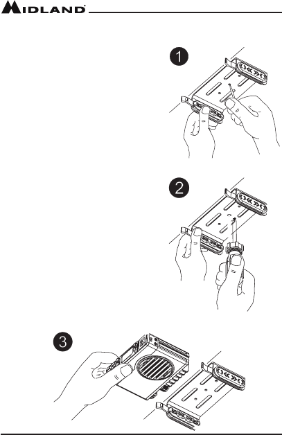
1. Using the mounting bracket as a
template, mark the location of each
screw hole under the dash. Use a
nail or other sharp pointed object to
mark the hole locations.
2. Attach the bracket to the dash with
the Phillips head sheet metal screws
provided. Tighten the screws
securely. DO NOT OVER-TIGHTEN.
3. Slide the radio into the mounting
bracket. BE SURE the mounting
bracket retainers engage the slots
in the sides of the radio to prevent
movement while driving.
Installing the Mounting Bracket

Page 7
midlandusa.com
Model MXT105
Installing the Antenna
The MXT105 includes a “magnetic mount” antenna, intended to be
attached to the vehicle’s roof, trunk or similar location. Specic installation
requirements vary between vehicles. Use the following guidelines to install
the antenna.
*Where you locate your antenna does make a difference.*
1. Some general rules for antenna location that can aid radio
performance.
2. Metal surfaces covered by berglass or vinyl may affect radio range.
Avoid these locations.
3. Mount the antenna as high on the vehicle as possible. The higher the
better.
4. If possible, mount the antenna in the center of whatever surface you
choose.
5. The antenna cable is 19.7 feet (6 meters) long. Be sure the mounting
location will allow for connection of the cable to the radio.
6. Be sure the mounting location is clean and dry before installing the
antenna.
7. Route the antenna cable through an accessible entry point, such as a
rear door or trunk opening.
8. When routing the antenna cable inside the vehicle, keep the cable
away from noise sources, such as the ignition system, gauges, etc.
9. Exercise care to prevent cable damage. Make use of existing gaskets,
grommets and weather stripping to protect the cable along its route.

Page 8 midlandusa.com
Model MXT105
Electrical and Rear Panel Connections
Refer to Rear Panel Connections for rear panel connector locations.
NOTE: Radio antenna is installed separately.
1. The power cord supplied with the MXT105 is equipped with a cigarette
lighter adapter for easy installation. Simply plug the connector into the
vehicle’s cigarette lighter. If a “hard-wired” installation is desired, connect
the power cord to the vehicle’s electrical system as follows:
▪Cut the power cord just after the cigarette lighter adapter.
▪Connect the positive lead (RED wire with in-line fuse holder) to
either (a) the fuse block or (b) directly to the positive post of the
vehicle’s battery.
NOTE: The fuse block is usually the most convenient connection
point. The power cord positive lead can also be connected to the
Accessory terminal on the fuse block or ignition switch, so the radio
automatically turns off when the ignition is turned off.
▪Securely connect the ground lead (BLACK wire) directly to the
vehicle’s metal frame. A good direct metal-to-metal ground is
essential for optimum performance.
2. Connect the 2-pin plug-in connector of the power cable to the 13.8V DC
jack on the rear panel.
3. Attach the antenna cable to the ANT jack on the rear panel.
4. If desired, an optional external speaker (purchased separately) can be
connected to the EXT SPKR jack (see Using an External Speaker).
Connecting the Microphone
Insert the RJ11 connector into the front of the MXT105. Once the
microphone is connected, use a small tool to insert the strain relief.
The microphone bracket can then be attached to the vehicle dash or other
convenient location in a manner similar to the mounting bracket.
Page 9
midlandusa.com
Model MXT105
Using an External Speaker
The MXT105 provides a rear-panel jack for connection of an optional
external speaker (purchased separately).
When selecting an external speaker, ensure the speaker has 8-ohm
impedance and is rated for 4.0 watts.
NOTE: When an external speaker is connected, the radio’s internal
speaker is automatically disabled.
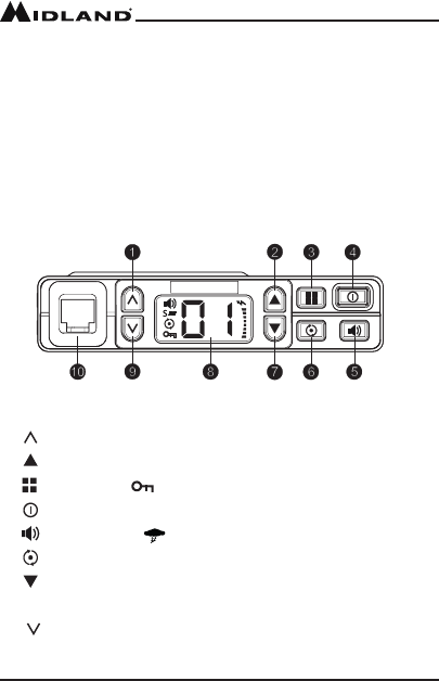
CONTROLS AND INDICATORS
Operating Controls
1. Volume Up
2. Channel Up
3. Menu and Lock
4. Power On/Off and Display Brightness
5. Monitor and Weather Channel
6. Scan
7. Channel Down
8. LCD Display
9. Volume Down
10. Microphone Jack
Page 10 midlandusa.com
Model MXT105
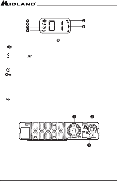
LCD Display
1. Receiving Icon - Indicates the radio is receiving transmission
from another user.
2. - CTCSS / DCS Icon - Indicates a Continuous Tone Coded
Squelch System (CTCSS) or Digitally Coded Squelch (DCS) Privacy
Code has been enabled for the currently selected channel.
3. Scanning Icon - Indicates the “auto-scan” function is active.
4. Keypad Lock Icon - Indicates the keypad lock is currently
enabled.
5. Channel Icon - Shows the selected transmit/receive channel.
6. RX/TX Icon - Indicates the strength of the current transmit or receive
signal.
7. Transmitting Icon - Indicates the radio is transmitting to another
user.
Rear Panel Connections
1. ANT Jack - SO-239 UHF connector for external antenna (included)
2. EXT SPKR Jack - 3.5mm Audio connector for optional external speaker
(purchased separately) (see Using an External Speaker for
specications).
3. 13.8V DC Jack - 2-pin DC connector for 12V DC nominal input power
connection

Page 11
midlandusa.com
Model MXT105
OPERATING YOUR RADIO
About Range
Your MXT105 is designed to give you maximum operating range under
optimum conditions.
Optimum conditions for maximum operating range are:
▪Over water
▪In open rural areas without obstructions
▪On at areas where you can see the other radio user
To ensure you get maximum range:
▪Be sure to mount the antenna (included) as high as possible on your
vehicle
▪Be sure to set your radio to use Hi power (see Selecting the
Transmit (TX) Power Level)
Maximum Range / No Sight Obstruction
Medium Range / Partial Obstruction to Line of Sight
Short Range / Major Obstruction to Line of Sight

Page 12 midlandusa.com
Model MXT105
Power On/Off
To turn the radio on and off:
1. With the radio off, press and hold the Power On/Off button for two
seconds to turn the radio on.
▪The LCD display will show all icons for one second and then display
the most recently selected channel.
2. With the radio on, press and hold the Power On/Off button for two
seconds to turn the radio off.
▪The LCD display will go blank when the radio turns off.
Selecting the Active Channel
IMPORTANT! To communicate between two MXT105 radios, both radios
must be set to the same channel and Privacy Code (see Selecting a
Privacy Code) selections.
To select the active channel:
1. Be sure the radio is turned on (see Power On/Off)
2. Press the Channel Up button to scroll forward through the
available channels. Press the Channel Down button to scroll
backward through the available channels.
▪The Channel icon on the LCD display will show the currently
selected channel.
Transmitting and Receiving a Call
IMPORTANT! To communicate between two MXT105 radios, both
radios must be set to the same channel (see Selecting a Privacy Code)
selections.
To transmit and receive a call:
1. Be sure the radio is turned on (see Power On/Off)
2. To transmit a call, press and hold the PTT button on the microphone,
and speak into the microphone in a normal voice.
NOTE: For maximum clarity, hold the microphone 2 to 3 inches from your
mouth when speaking.

Page 13
midlandusa.com
Model MXT105
▪The RX/TX icon will show continuously on the LCD display while
transmitting.
3. To receive a call, release the PTT button on the microphone.
▪The RX/TX icon will show on the LCD display when your radio is
receiving a transmission.
4. If necessary, press the Volume Up or Volume Down button to
increase or decrease radio volume.
UTILITY FUNCTIONS
Utility functions let you congure several operational parameters of the
MXT105 to suit your personal preferences. For additional utility functions,
“MENU” MODE FUNCTIONS.
Flipping the Display
The MXT105 incorporates a unique Display Flip function that allows the
unit to be installed upside-down, if required, and the display read from
either orientation.
To “ip” the LCD display:
1. Be sure the radio is turned off (see Power On/Off)
2. Press and hold the Channel Down button, then press and hold the
Power On/Off button for two seconds to turn the radio on.
▪The LCD display will rotate 180° from its most recent orientation.
3. Repeat steps 1 and 2 to return the LCD display to its previous
orientation.
Locking the Keypad
You can use the keypad “lock” function to prevent accidentally changing
your radio’s settings. When the function is enabled, the current radio
settings are “locked” in place.
NOTE: When the “lock” function is enabled, the PTT button on the
microphone and the Volume Up / Volume Down buttons on the
radio remain active.

Page 14 midlandusa.com
Model MXT105
To “lock” and “unlock” the keypad:
1. Be sure the radio is turned on (see Power On/Off)
2. Press and hold the Menu button for two seconds.
▪The Keypad Lock icon will show on the LCD display when the
keypad is “locked.”
3. Repeat steps 1 and 2 to “unlock” the keypad.
▪The Keypad Lock icon will turn off when the keypad is
“unlocked”
Adjusting the Display Illumination
You can adjust the illumination of the LCD display to ensure optimum
visibility under various daytime and night-time lighting conditions. There
are ve levels of illumination, from off to full brightness.
To adjust display brightness:
1. Be sure the radio is turned on (see Power On/Off)
2. Briey press and release the Power On/Off button.
▪Each time the button is pressed and released, the display
illumination increases to the next brightness level.
▪When the maximum brightness level is reached and the button is
pressed and released, the display illumination turns off.
Using Monitor Mode
Monitor mode lets you check for activity on the current active channel. You
can also use Monitor mode to adjust the volume of your radio when not
receiving a signal.
To enter and exit Monitor mode:
1. Be sure the radio is turned on (see Power On/Off)
2. Be sure you have selected the desired channel (see Selecting the
Active Channel)
3. Briey press and release the Monitor/Quiet Channel button to
enter Monitor mode.
▪You will hear any activity on the current selected channel.
Page 15
midlandusa.com
Model MXT105
4. Press the Volume Up or Volume Down button to increase or
decrease radio volume.
5. Once the radio volume has been adjusted to the desired level, briey
press and release the Monitor/Quiet Channel button to exit
Monitor mode.
NOAA Weather Radio/Scan
Your MXT105 has a NOAA Weather Radio function, to enable the user to
receive weather reports from designated NOAA stations. Your radio also
has a NOAA Weather Scan function, to enable the user to scan all 10
channels of the NOAA Weather Radio.
To turn the NOAA Weather Band on, Long press the Monitor button
while in GMRS mode.
▪The radio will go to WX Band mode and start scanning all 10
channels and stop on any active channel.
▪When the channel becomes inactive for 10 seconds the radio will
resume scanning.
- To have radio re-scan all weather channels press and release the
Scan button
▪To exit the Weather band, press the PTT button or press and hold
the Monitor button

Page 16 midlandusa.com
Model MXT105
Scanning for Active Channels
Your MXT105 includes an “auto-scan” mode that continuously scans all 15
available channels for activity. Additionally, if desired, you can remove one
or more channels from the list of scanned channels.
To enter and exit “auto-scan” mode:
1. Be sure the radio is turned on (see Power On/Off)
2. Quickly press and release the Scan button to enter “auto-scan”
mode
▪The Scanning icon will show on the LCD display when the radio
is in “auto-scan” mode
▪Your radio will rapidly scan through the 15 available channels and
will pause on any active channel.
▪“Auto-scan” will resume when there has been no activity on the
current channel for four seconds.
3. To transmit during “auto scan,” press and hold the PTT button on the
microphone while the radio is paused on the desired channel.
▪The radio will remain on the active channel for three seconds after
the PTT button is released.
4. To exit the “auto-scan” mode, quickly press and release the Scan
button.
▪The Scanning icon will turn off when the radio is no longer in
“auto-scan” mode.
To remove a channel from “auto-scan” mode:
1. Be sure the radio is turned on (see Power On/Off)
2. Use the Channel Up or Channel Down button to scroll forward
or backward through the available channels until the Channel icon for
the channel you wish to remove shows on the LCD display.
Page 17
midlandusa.com
Model MXT105
3. Press and hold the Scan button.
▪The selected channel is removed from the list of “scanned” channels
and will not be included in “auto-scan.”
4. Repeat steps 1 through 3 to return a removed channel to the list of
“scanned” channels.
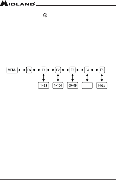
“MENU”MODE FUNCTIONS
The “Menu” mode provides access to the features and functions shown in
the chart below. For additional utility functions, see UTILITY FUNCTIONS.
MXT105 “Menu” Mode Quick Reference Chart
F1- CTCSS Codes. Use this option to select and assign a Continuous
Tone Coded Squelch System (CTCSS) Privacy Code for the currently
active channel.
F2- DCS Codes. Use this option to select and assign a Digitally Coded
Squelch (DCS) Privacy Code for the currently active channel.
F3 - Squelch Sensitivity. Use this option to adjust squelch sensitivity.
F4 - Silent Operation. Use this option to set the option for the keypad
audible “beep” tones.
F5 - Transmit Power Level. Use this option to change the transmit power
level to HI or LO.
Selecting a Privacy Code
Continuous Tone Coded Squelch System (CTCSS) and Digitally Coded
Squelch (DCS) are systems that allow several users to share the same
channel without disturbing each other. When CTCSS or DCS enabled for a
selected channel, the channel is muted to all incoming signals unless they
carry the correct CTCSS or DCS tone.
ON-OFF
Page 18 midlandusa.com
Model MXT105
When a transmission with the correct tone is received, the mute is
removed and the voice audio can be heard. When the transmission ends
the channel is muted again. Transmissions that do not have the correct
tone are not heard.
The MXT105 has 142 Privacy Codes (38 CTCSS codes and 104 DCS
codes), which can be applied to any channel. If desired, you can select
a different Privacy Code for each channel. See CTCSS Privacy Codes
Frequency Chart and DCS Privacy Codes Chart for lists of available
Privacy Codes.
IMPORTANT! To communicate between two MXT105 radios, both radios
must be set to the same channel (see Selecting the Active Channel) and
Privacy Code selections.
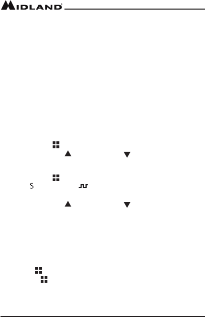
To select a Privacy Code:
1. Press the Menu button to a place the radio in “Menu” mode.
2. Use the Channel Up or Channel Down button to scroll the menu
options until the LCD display shows F1 (for CTCSS) or F2 (for DCS),
as desired.
3. Press the Menu button again to conrm your selection.
▪The (for CTCSS) or (for DCS) icon will show on the LCD
display, according to your selection.
4. Use the Channel Up or Channel Down button to scroll forward or
backward through the available Privacy Codes until the desired Privacy
Code is shown on the LCD display.
NOTE: DCS Privacy Codes 100-104 are shown on the LCD display as
A0-A4.
NOTE: Selecting a Privacy Code of “oF” will disable the Privacy feature.
5. When the desired Privacy Code is shown on the LCD display, press
the Menu button to conrm your selection. YOU MUST PRESS
THE MENU BUTTON TO CONFIRM YOUR SELECTION OR THE
PRIVACY CODE WILL NOT BE CHANGED.
NOTE: If you select a CTCSS Privacy Code, any pre-selected DCS
Privacy Code will be cancelled, and vice-versa.

Page 19
midlandusa.com
Model MXT105
Adjusting Squelch Sensitivity
The MXT105 has adjustable squelch sensitivity. The minimum squelch
level of 00 is the most sensitive, which allows the squelch to open on very
weak signals. Setting the squelch to the maximum setting of 09 requires
very strong signals to open the squelch.
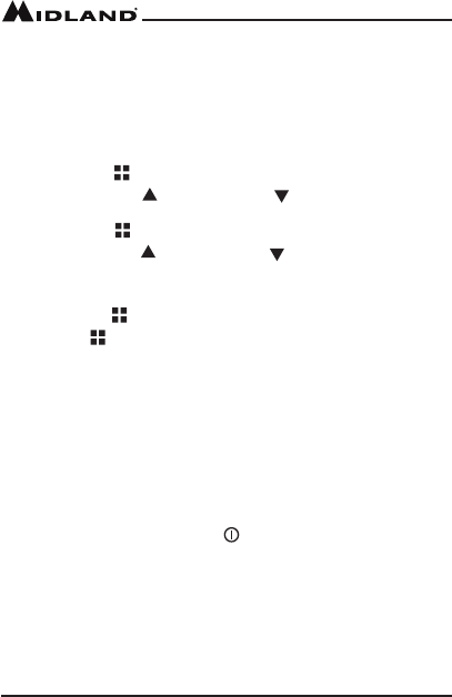
To adjust the squelch sensitivity:
1. Press the Menu button to place the radio in “Menu” mode.
2. Use the Channel Up or Channel Down button to scroll the menu
options until the LCD display shows F3.
3. Press the Menu button again to conrm your selection
4. Use the Channel Up or Channel Down button to scroll forward
or backward to select the desired squelch level, from 00 to 09.
▪The default squelch setting is 05, which generally provides reliable
squelch operation for most applications.
5. When the desired squelch level is shown on the LCD display, press
the Menu button to conrm your selection. YOU MUST PRESS
THE MENU BUTTON TO CONFIRM YOUR SELECTION OR THE
SQUELCH SENSITIVITY WILL NOT BE CHANGED.
Silent Operation
The MXT105 has a SILENT OPERATION mode. In this mode, all “beeps”
and “tones” are disabled.
To Set the Silent Operation:
1. Press the Menu button to place the radio in “Menu” mode.
2. Use the Channel Up or Channel Down button to scroll the menu
options until the LCD display shows F4
3. Press the Menu button again to conrm your selection.
4. Select “on” or “oF” by pressing the Channel Up or Channel Down
5. When your selection is made, press the Menu button (or wait 3
seconds) to conrm your selection.
Page 20 midlandusa.com
Model MXT105
Selecting the Transmit (TX) Power Level
The MXT105 provides two transmit power levels; HI and Lo. the Lo power
level is generally suitable when operating under optimum conditions (see
About Range). The HI power level is recommended to ensure you get
maximum range from your radio.
To adjust the transmit power level:
1. Press the Menu button to place the radio in “Menu” mode.
2. Use the Channel Up or Channel Down to scroll the menu
options until the LCD display shows F5
3. press the Menu button again to conrm your selection.
4. Use the Channel Up or Channel Down button to toggle the
transmit power setting between HI and Lo.
5. When the desired transmit power level is shown on the LCD display,
press the Menu button to conrm your selection. YOU MUST PRESS
THE MENU BUTTON TO CONFIRM YOUR SELECTION OR THE
POWER LEVEL WILL NOT BE CHANGED.
RESTORING THE DEFAULT SETTINGS
You can restore the original (factory default) settings for your MXT105 at
any time.
To restore the default settings:
1. Be sure the radio is turned off (see Power On/Off).
2. Press and hold the Volume Up button.
3. Press and hold the Power On/Off button for two seconds to turn the
radio on.
4. Release both buttons.
▪The radio will enter “standby” mode at channel 1, with no Privacy
Code selected.
>

Page 21
midlandusa.com
Model MXT105
CARE AND MAINTENANCE
CAUTION: DO NOT use alcohol or cleaning solutions to clean the
radio. DO NOT immerse the radio in water.
1. Use a soft cloth moistened with water to clean the radio.
2. Dry the radio with a dry lint-free cloth should it get wet.
TROUBLESHOOTING GUIDE
If you experience difculties using your MXT105, refer to the following
chart to correct common operation problems. If you have a problem which
you believe requires service, please call rst and speak with a service
technician at 816-241-8500. Many problems can be remedied over the
phone without returning the unit for service.
.
PROBLEM
No Power
Cannot Receive
Messages
Check vehicle power source (battery); replace
as needed.
Check input power connection and/or wires to
vehicle power source.
Verify both radios have the same channel
selection and Privacy Code settings.
Conrm communication is not affected by buildings
and other structures ( see About Range)
Make sure keypad “lock” is not on
(see Locking the Keypad)
Adjust the display illumination
(see Adjusting the Display Illumination)
Make sure you are within range of the other radio.
Reset the radio ( turn radio off then back on)
Keypad is not
Responding
Display Backlight
is Dim
SOLUTION
Page 22 midlandusa.com
Model MXT105
SPECIFICATIONS
Channels:
Privacy Codes:
Operating Frequency:
Power Source:
15 GMRS Channels and
10 NOAA Weather Channels
38 CTCSS; 104 DCS
UHF; 462.5500 ~ 462.725 MHz
13.8 VDC Nominal
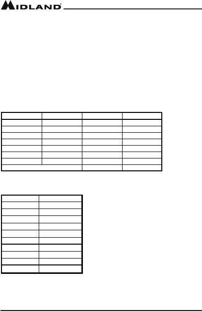
GMRS Frequency Chart
Ch. No. Ch. Freq. (MHz) Ch. No. Ch. Freq. (MHz)
1 462.5625 15 462.550
2 462.5875 16 462.575
3 462.6125 17 462.600
4 462.6375 18 462
5 462.6625 19 462.650
6 462.6875 20 462.675
7 462.7125 21 462.700
Ch 8 ~ 14 Reserved for FRS 22 462.725
WX Band Channels
.625
162.550
162.400
162.475
162.425
162.450
162.500
162.525
161.650
161.775
163.275
1
2
3
4
5
6
7
8
9
10
Channel Number Frequency (MHz)

Page 23
midlandusa.com
Model MXT105
CTCSS Privacy Codes Frequency Chart
Code Freq. Code Freq. Code Freq. Code Freq Code Freq
1 67.0 9 9 1.5 17 118.8 25 156.7 33 210.7
2 71.9 10 94.8 18 123.0 26 162.2 34 218.1
3 74.4 11 97.4 19 127.3 27 167.9 35 225.7
4 77.0 12 100.0 20 131.8 28 173.8 36 233.6
5 79.7 13 103.5 21 136.5 29 179.9 37 241.8
6 82.5 14 107.2 22 141.3 30 186.2 38 250.3
7 85.4 15 110.9 23 146.2 31 192.4
8 88.5 16 114.8 24 151.4 32 203.5
9
DCS Privacy Codes Chart
No. Code No. Code No. Code No. Code
1 23 27 165 53 413 79 731
2 25 28 172 54 423 80 732
3 26 29 174 55 431 81 734
4 31 30 205 56 432 82 743
5 32 31 223 57 445 83 754
6 43 32 226 58 464 84 36
7 47 33 243 59 465 85 53
8 51 34 244 60 466 86 122
9 54 35 245 61 503 87 145
10 65 36 251 62 506 88
2
12
11 71 37 261 63 516 89
2
25
12 72 38 263 64 532 90
2
46
13 73 39 265 65 546 91
2
52
14 74 40 271 66 565 92
2
55
15 114 41 306 67 606 93 266
16 115 42 311 68 612 94 274
17 116 43 315 69 624 95 325
18 125 44 331 70 627 96 332
19 131 45 343 71 631 97 356
20 132 46 346 72 632 98 446
21 134 47 351 73 654 99 452
22 143 48 364 74 662 100
4
54
23 152 49 365 75 664 101
4
55
24 155 50 371 76 703 102
4
62
25 156 51 411 77 712 103
5
23
26 162 52 412 78 723 104 526
Page 24 midlandusa.com
Model MXT105
2-Way Radios
2-Way Radios
Weather Radios
Emergency Crank Radios
HD Wearable Video Cameras
CB Radios
Page 25
midlandusa.com
Model MXT105
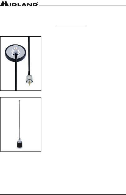
ACCESSORIES
Accessories can be purchased at midlandusa.com
MXTA3
Antenna Magnetic Mount
$39.99
MXTA5
Antenna Magnetic Mount
$29.99

Page 26 midlandusa.com
Model MXT105
LIMITED WARRANTY (United States and Canada)
Subject to the exclusions set forth below, Midland Radio Corporation will repair or replace,
at its option without charge, any Midland FRS/GMRS which fails due to a defect in
material or workmanship within One Year following the initial consumer purchase.
This warranty does not apply to water damage, battery leak, abuse or misuse of
unauthorized accessories, unauthorized service or modication or altered products.
Accessories have a 90 day warranty from date of purchase, including any charge cables
or batteries.
ANY IMPLIED WARRANTIES, INCLUDING, WITHOUT LIMITATION THE IMPLIED
WARRANTIES OF MERCHANTABILITY AND FITNESS FOR A PARTICULAR
PURPOSE, SHALL BE LIMITED AS SET FORTH HEREIN AND TO THE DURATION
OF THE LIMITED WARRANTY, OTHERWISE THE REPAIR OR REPLACEMENT AS
PROVIDED UNDER THIS EXPRESS LIMITED WARRANTY IS THE EXCLUSIVE
REMEDY OF THE CONSUMER AND IS PROVIDED IN LIEU OF ALL OTHER
WARRANTIES, EXPRESS OR IMPLIED. IN NO EVENT SHALL MIDLAND BE
LIABLE, WHETHER IN CONTRACT OR TORT (INCLUDING BUT NOT LIMITED TO
NEGLIGENCE, GROSS NEGLIGENCE, BODILY INJURY, PROPERTY DAMAGE
AND DEATH) FOR DAMAGES IN EXCESS OF THE PURCHASE PRICE OF THE
PRODUCT OR ACCESSORY, OR FOR ANY INDIRECT, INCIDENTAL, SPECIAL OR
CONSEQUENTIAL DAMAGES OF ANY KIND, OR LOSS OF REVENUE OR PROFITS,
LOSS OF BUSINESS, LOSS OF INFORMATION OR DATA OR OTHER FINANCIAL
LOSS ARISING OUT OF OR IN CONNECTION WITH THE ABILITY OR INABILITY TO
USE THE PRODUCTS OR ACCESSORIES TO THE FULL EXTENT THESE DAMAGES
MAY BE DISCLAIMED BY LAW.
For Product Purchased in the USA:
Performance of any obligation under this warranty may be obtained
by returning the warranted product, prepaid freight, along with proof of
purchase to:
Midland Radio Corporation
Warranty Service Department
5900 Parretta Drive
Kansas City, MO 64120
This warranty gives you specic legal rights, and you may also have other
rights, which vary from state to state.
NOTE: The above warranty applies only to merchandise purchased in the United
States of America or any of the territories or possessions thereof, or from a U.S. Military
exchange.
For Product Purchased in Canada:
Performance of any obligation under this warranty may be obtained by returning the
warranted product, along with proof of purchase, to your place of purchase in Canada.
This warranty gives you specied legal rights. Additional warranty rights may be provided
by law in some areas within Canada.

Page 27
midlandusa.com
Model MXT105
THIS PAGE IS
INTENTIONALLY
LEFT BLANK

Note: Features and Specications are subject to change without
notice. MIDLAND RADIO CORPORATION is not responsible for
unintentional errors or omissions on its packaging.
We’d love to hear from you! Let us know what
you think of your new Midland product at:
or by visiting us at:
midlandusa.com
MIDLAND RADIO CORPORATION
5900 Parretta Drive
Kansas City, MO 64120
Call 816.241.8500