Midland Radio PL450 PL1145/PL2245 Mobile Radio User Manual ProLine1
Midland Radio Corporation PL1145/PL2245 Mobile Radio ProLine1
UserManual.wiki
>
Midland Radio
>
PL450 User Manual
>
manual
Contents
1.
manual
2.
FCC Proline 1 to 2
3.
Rev C PL 1145 book
4.
REV B PL 2245
manual
Navigation menu
Upload a User Manual
Namespaces
Wiki Guide
HTML
PDF
Info
Views
User Manual
Discussion / Help
Navigation

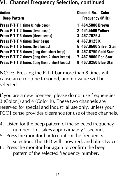
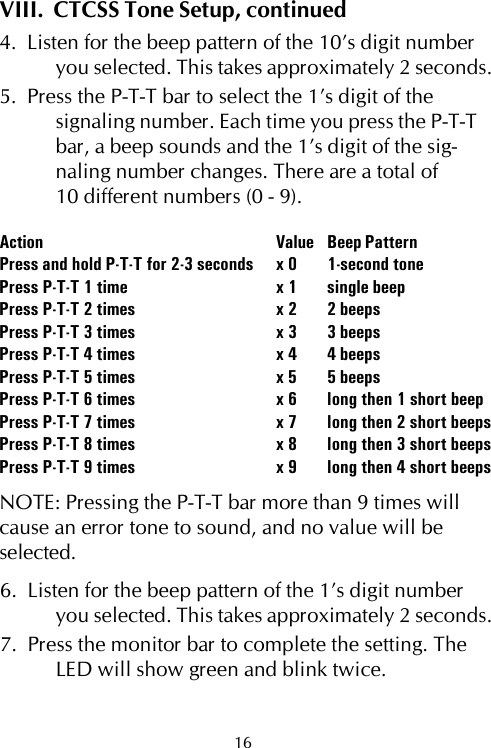
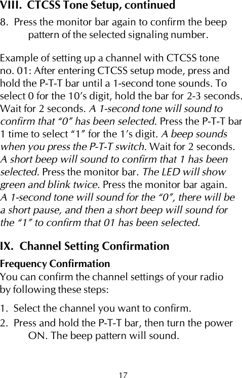
![IX. Channel Setting Confirmation, continuedFrequency Confirmation, continued[i.e.- If frequency 3 (Color J) is set up on thechannel, 3 short beeps will sound.]CTCSS Tone ConfirmationNOTE: There will be a short pause between theconfirmation of the 10’s digit and the confirmationof the 1’s digit.1. Press and hold the monitor bar, then turn the powerON. The beep pattern will sound. [i.e – If CTCSStone 01 is set up on the channel, a 1-second tonewill sound (0), there will be a short pause, andthen a short beep will sound (1).Confirmation Beep SettingsNumber Beep Pattern Number Beep Pattern0 1-second tone 5 five beeps1 single beep 6 long then short beep2 two beeps 7 long then 2 short beeps3 three beeps 8 long then 3 short beeps4 four beeps 9 long then 4 short beepsFactory Default Channel Setting - Model PL1145Channel 1 Yellow (464.5500MHz) Code no. 01 (67Hz)18](https://usermanual.wiki/Midland-Radio/PL450.manual/User-Guide-132901-Page-23.png)