Midland Radio PL5164 PL5164 Portable Radio User Manual Table of Contents
Midland Radio Corporation PL5164 Portable Radio Table of Contents
UserManual.wiki
>
Midland Radio
>
PL5164 User Manual
>
122001 Manual
Contents
1.
122001 Manual
2.
022002 Manual revised
3.
030602 Manual revised
4.
050302 Manual Revised
5.
Revised Users Manual
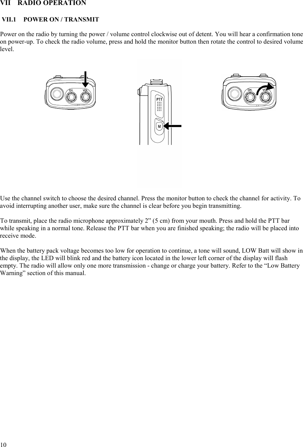
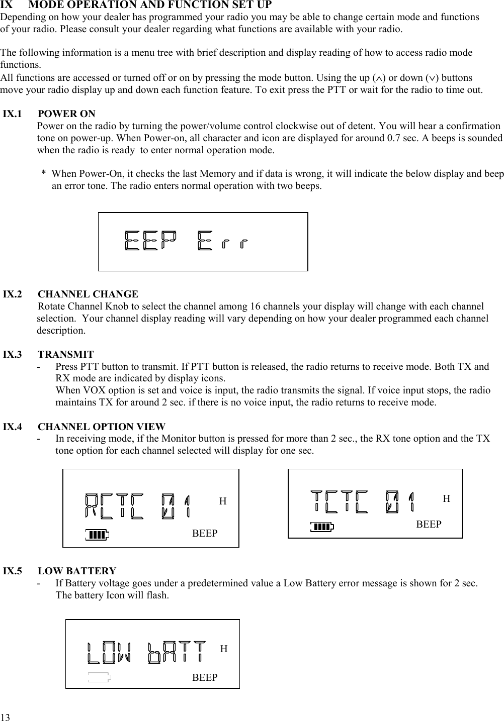
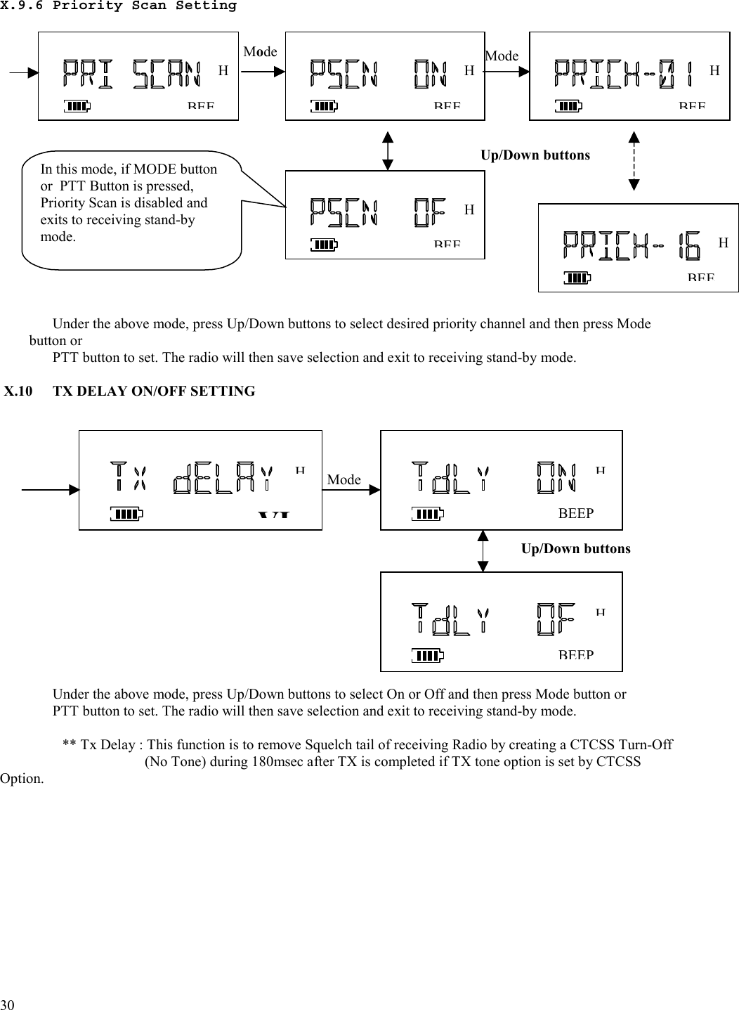
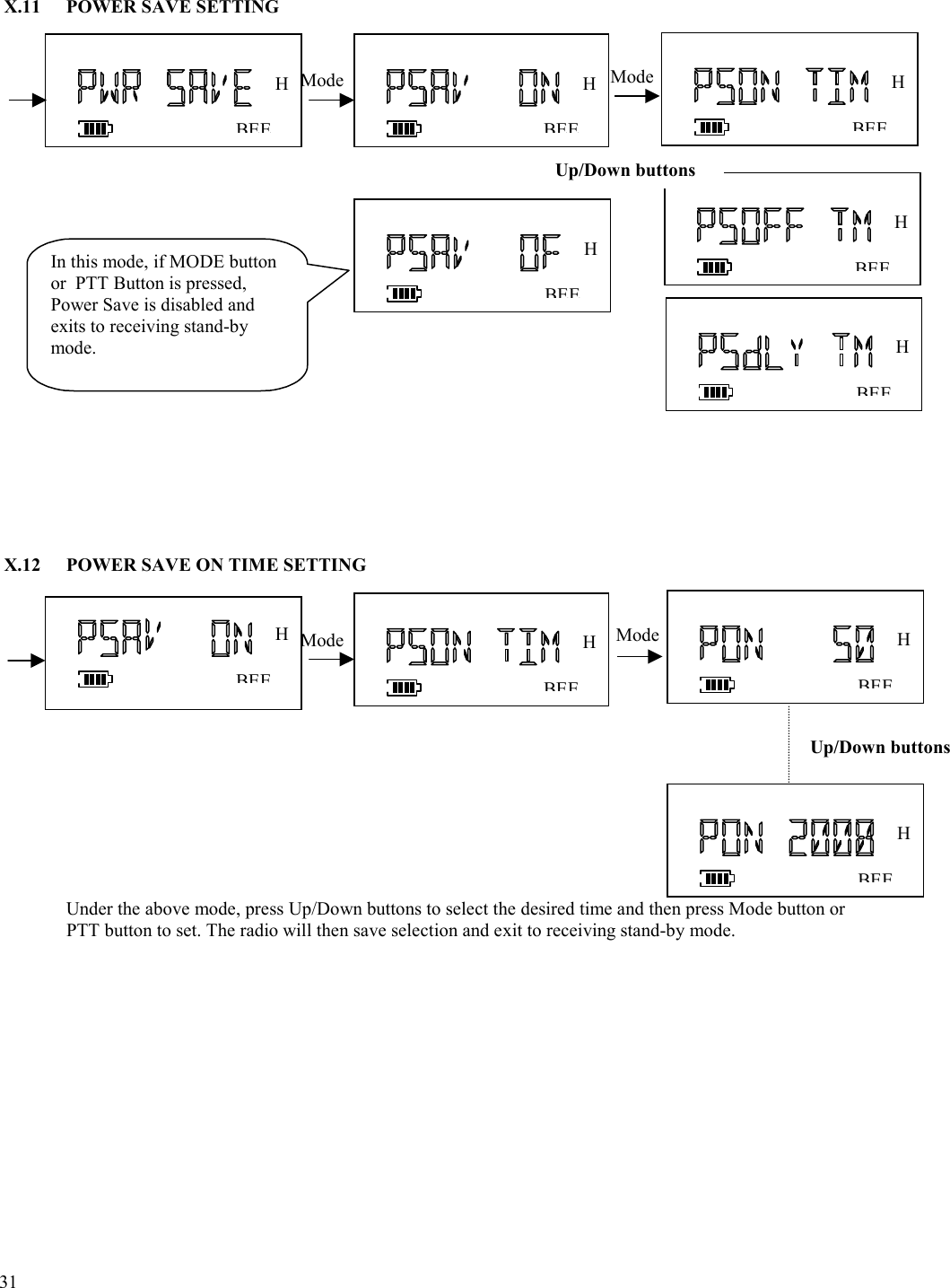
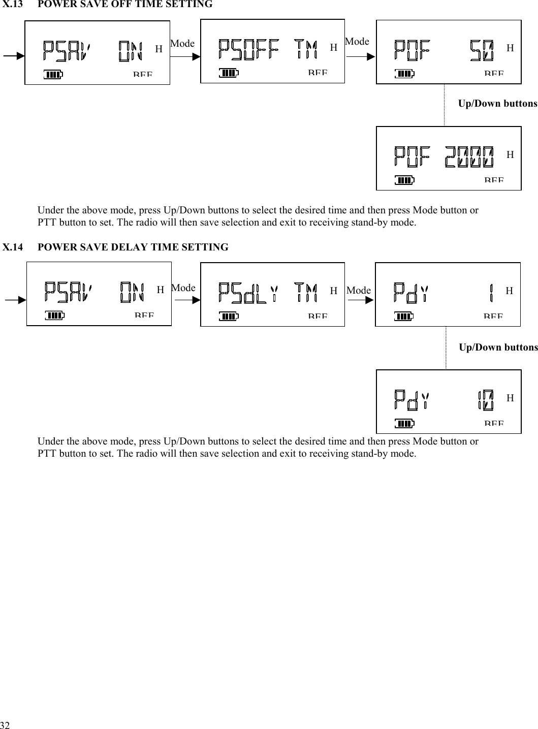
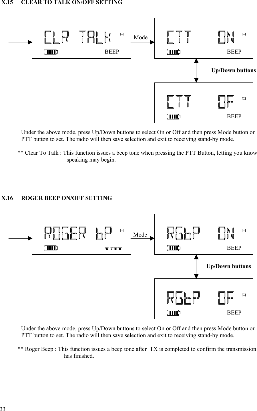
122001 Manual
Navigation menu
Upload a User Manual
Namespaces
Wiki Guide
HTML
PDF
Info
Views
User Manual
Discussion / Help
Navigation