Midland Radio RG2 Marine Transceiver User Manual ISTR NEPT UK indd
Midland Radio Corporation Marine Transceiver ISTR NEPT UK indd
UserManual.wiki
>
Midland Radio
>
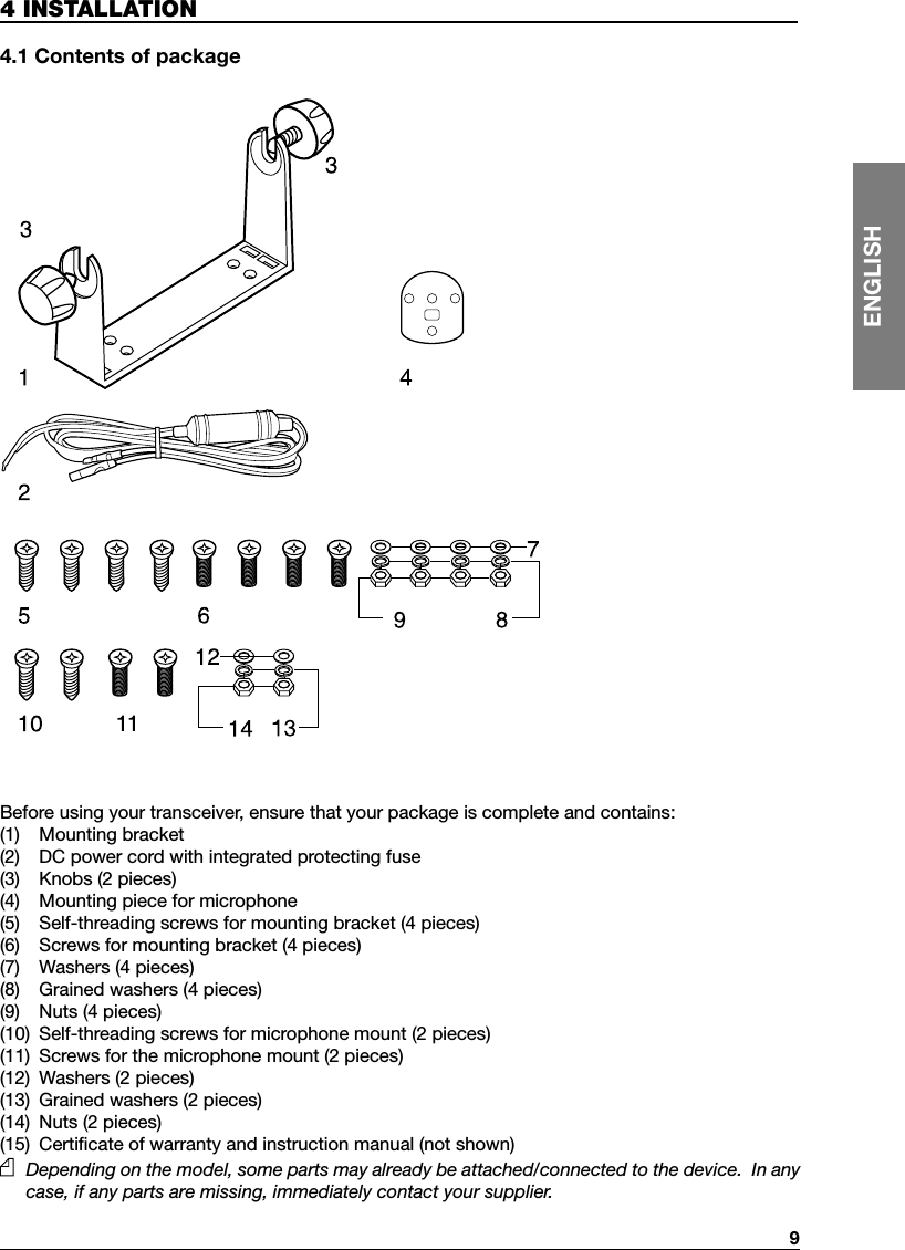
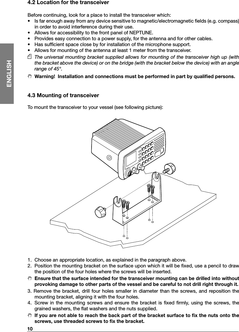
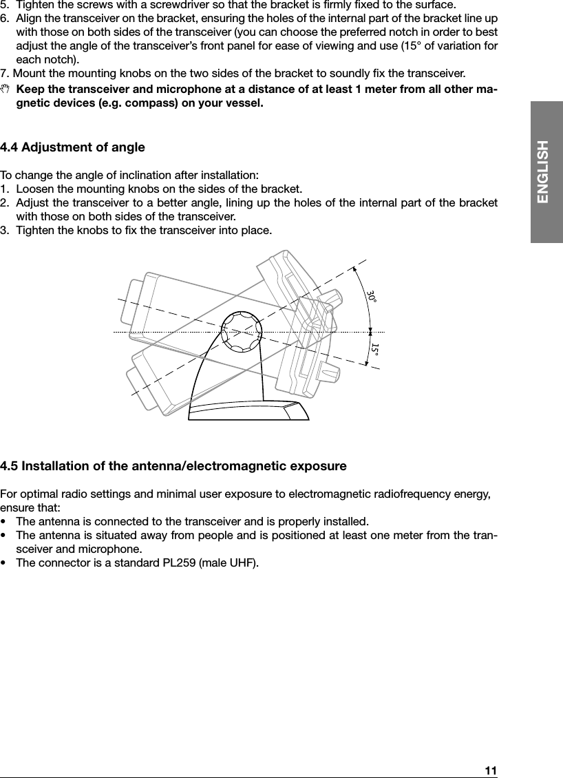
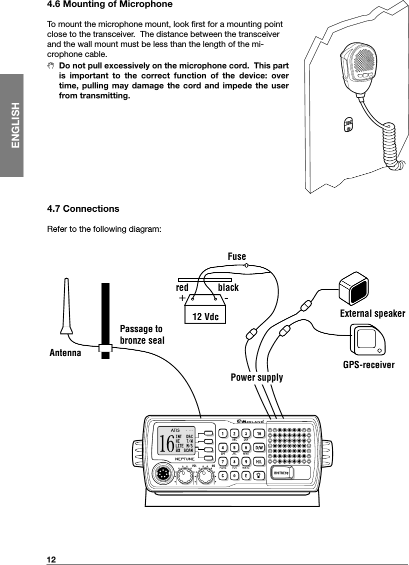
RG2 User Manual
users manual
Navigation menu
Upload a User Manual
Namespaces
Wiki Guide
HTML
PDF
Info
Views
User Manual
Discussion / Help
Navigation