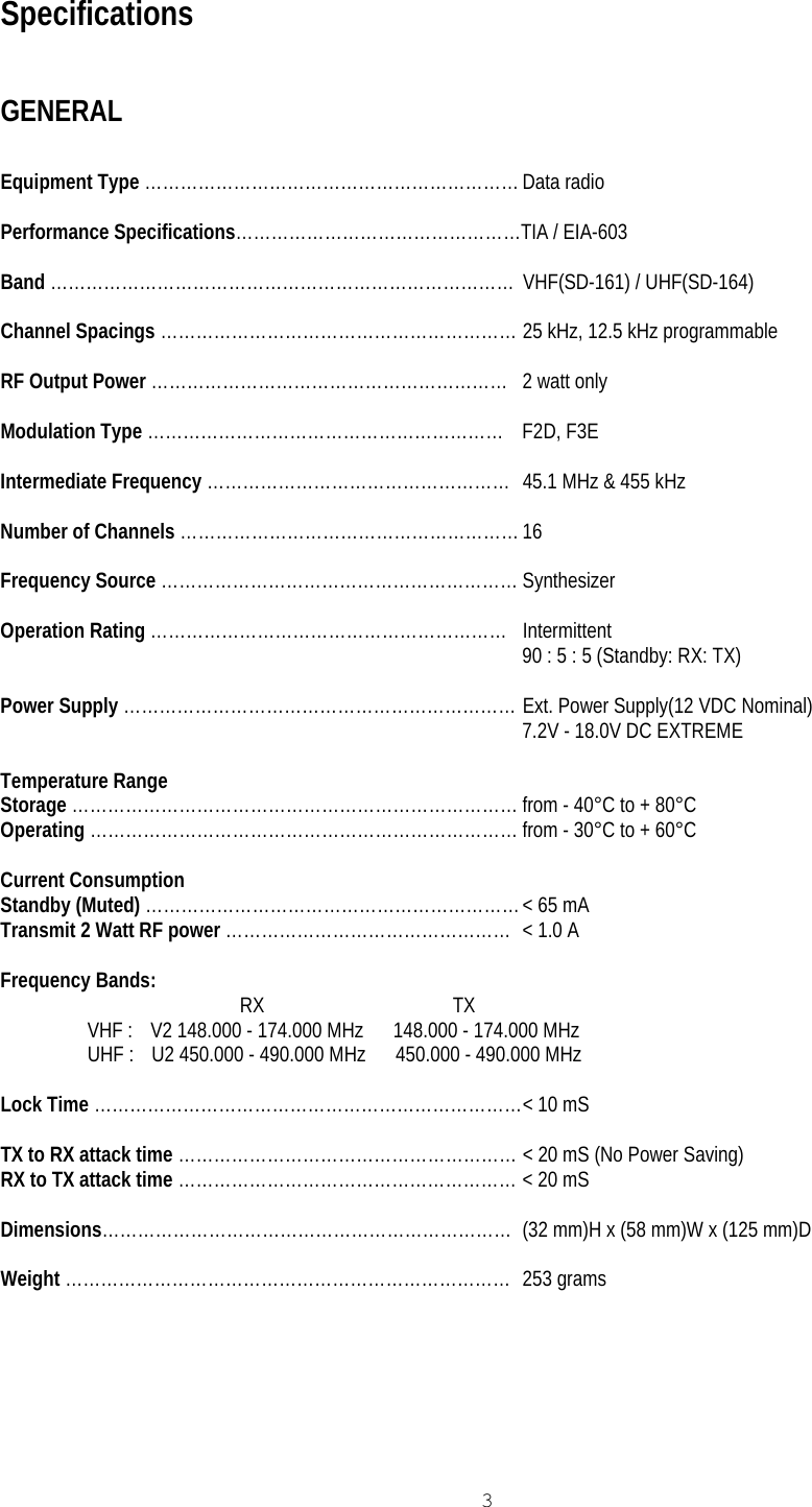
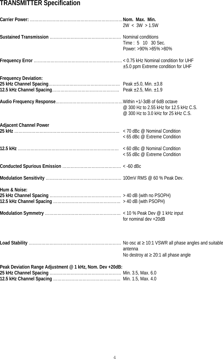
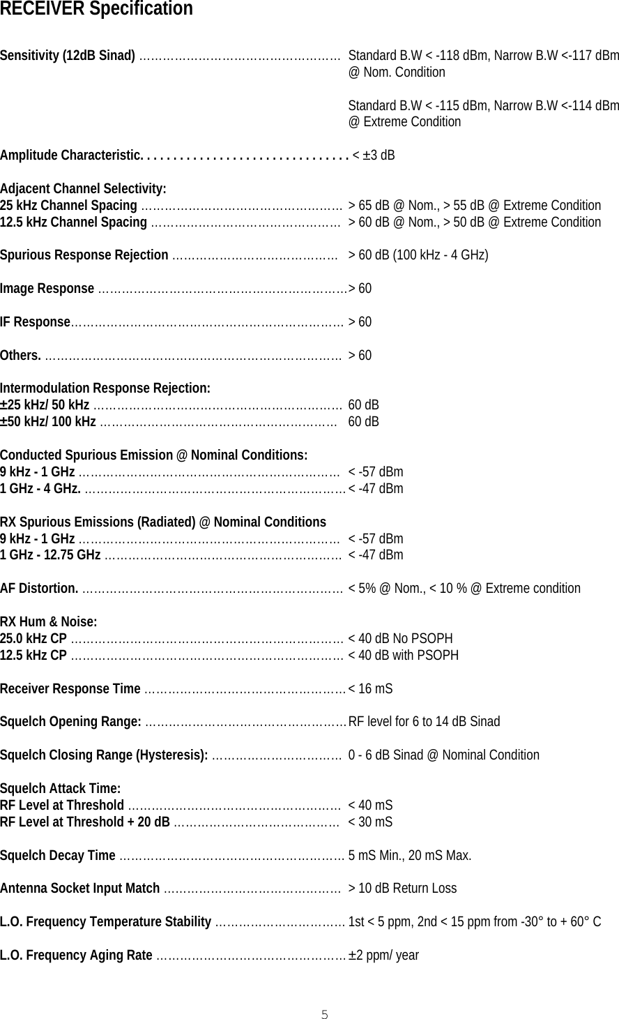
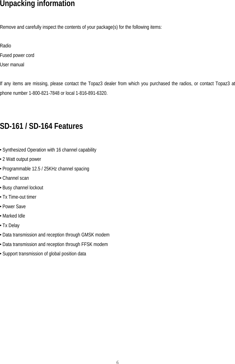
Midland Radio SD161 VHF Radio Transmitter User Manual Specifications
Midland Radio Corporation VHF Radio Transmitter Specifications
UserManual.wiki
>
Midland Radio
>
SD161 User Manual
users manual
Navigation menu
Upload a User Manual
Namespaces
Wiki Guide
HTML
PDF
Info
Views
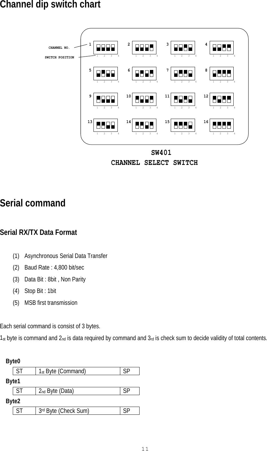
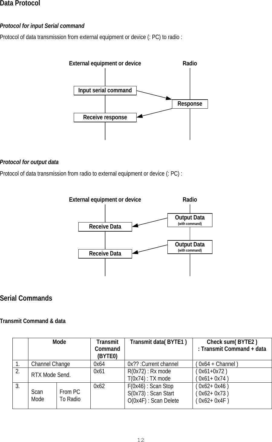
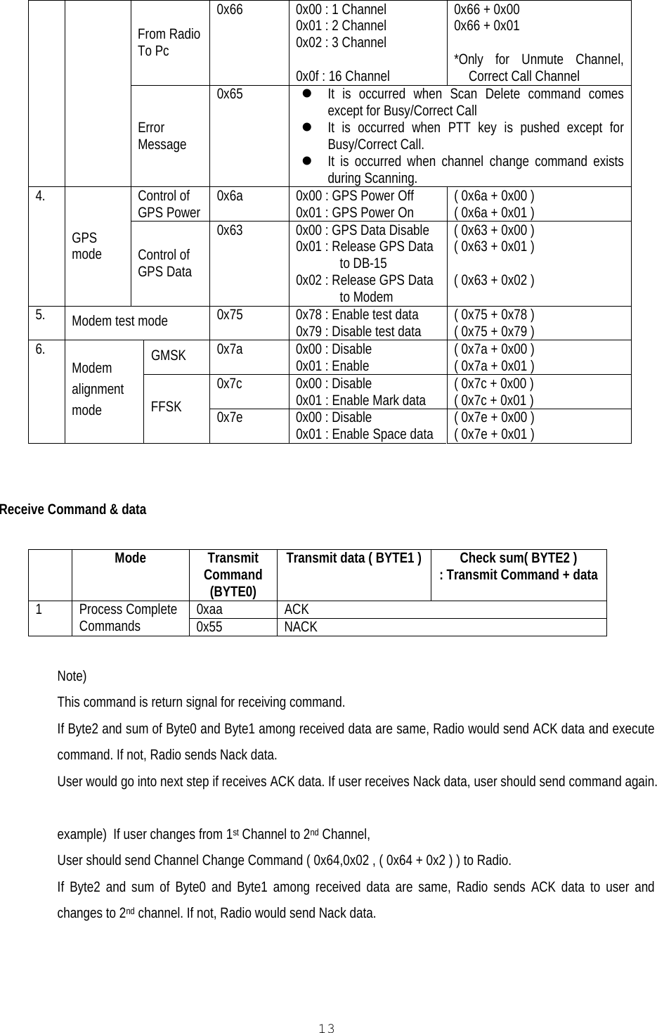
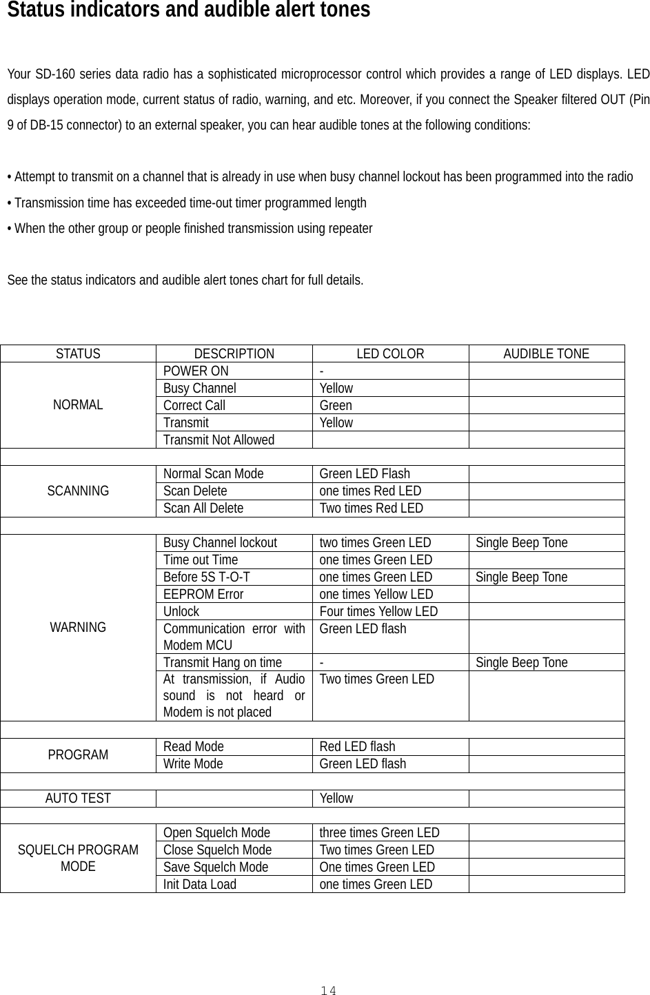
User Manual
Discussion / Help
Navigation