Midland Radio SD164 UHF Data Transceiver - Transmitter User Manual User s manual
Midland Radio Corporation UHF Data Transceiver - Transmitter User s manual
users manual
SD-164
Data Radio
User Instruction Manual
FCC RF Exposure Compliance Requirements -
The Federal Communications Commission (FCC), with its action
in General Docket 93-62, November 7, 1997, has adopted a
safety standard for human exposure to Radio Frequency (RF) electromagnetic energy emitted by FCC regulated equipment.
Topaz3 / Maxon subscribes to the same safety standard for the
use of its products. Proper operation of this radio will result in
user exposure far below the Occupational Safety and Health Act (OSHA) and Federal Communications Commission limits.
Antennas used for this transmitter must not exceed an antenna gain of 7dBd. The radio must be used in config-
urations with a maximum operating duty factor not exceeding 50%, in typical push-to-talk configurations. This radio is
approved for use by the general population in an uncontrolled environment. The antenna(s) used for this transmitter
must be installed to provide a separation distance of at least 49cm from all persons, must not be co-located or operating
in conjunction with asny other antenna or transmitter.
CAUTION - DO NOT transmit for more than 50% of total radio use time (50% duty cycle). Transmitting more than 50% of the
time can cause FCC RF exposure compliance requirements to be exceeded. The radio is transmitting when the “TX” icon on
the radio display is illuminated. You can cause the radio to transmit by pressing the P-T-T button on the radio’s microphone.
Users must be provided with antenna installation instructions and transmitter operating conditions for satisfying RF
exposure compliance.
NOTE: This radio operates in FCC regulated frequency bands.
All radios must be licensed by the FCC before use. Because this radio contains a transmitter, Federal law prohibits
unauthorized use or adjustments of this radio.
This device complies with Part 15 of the FCC Rules. Operation is subject to the condition that this device does not cause
harmful interference.
Safety
CAUTION - DO NOT operate the transmitter of any radio unless all RF connectors are secure and any open
connectors are properly terminated.
CAUTION - DO NOT operate the radio near electrical blasting caps or in an explosive atmosphere.
CAUTION - All equipment must be properly grounded for safe operation.
WARNING - DO NOT allow children to operate transmitter - equipped radio equipment.
WARNING - All equipment should be serviced by a qualified technician.
WARNING - It is mandatory that radio installations in vehicles fueled by liquefied petroleum gas conform to the following
standard: National Fire Protection Association Standard NFPA 58 applies to radio installations in vehicles fueled
by liquefied petroleum (LP) gas with LP gas container in the trunk or other sealed-off space
within the interior of the vehicle. This standard requires that:
1. Any space containing radio equipment shall be isolated by a seal from the space in which the LP gas container and its
fittings are located.
2. Remote (outside) filling connections shall be vented to the outside.
2
About your SD-164 Data Radio
The SD-160 Series (hereinafter called “the radios”) of RF Link Modules from Topaz3 utilize the latest technology in their
designs and manufacturing. SD-164 models are Phase Lock Loop Synthesizer (PLL) / microprocessor controlled and offer
two (2) watts of power with 16-channel capability. Multiple functions including 1200 to 9600 baud rates, AC and/or DC
audio coupling, GMSK, FFSK and FSK modulation are standard in these fully programmable wide bandwidth RF Link
Module units. Programmable sub-audio squelch system (CTCSS & DCS) and two-tone squelch system are newly added to
the signal level detect squelch system (RSSI). GPS Data handling is provided to interface and control internal GPS receiver.
To assure satisfaction from the radio, we urge you to thoroughly read the operation and function information in this manual
before operating your SD-164.
Applications of some of the functions described in this manual are determined by the system you use. Your Topaz3 dealer
will program your radio so that you have the greatest number of functions possible relative to your needs.
Should you have questions regarding the operation of the radio, please consult your Topaz3 Dealer.
3
Specifications
GENERAL
Equipment Type ……………………………………………………… Data radio
Performance Specifications…………………………………………TIA / EIA-603
Band …………………………………………………………………… UHF
Channel Spacings …………………………………………………… 25 kHz, 12.5 kHz programmable
RF Output Power …………………………………………………… 2 watt only
Modulation Type …………………………………………………… F2D, F3E
Intermediate Frequency …………………………………………… 45.1 MHz & 455 kHz
Number of Channels ………………………………………………… 16
Frequency Source …………………………………………………… Synthesizer
Operation Rating …………………………………………………… Intermittent
90 : 5 : 5 (Standby: RX: TX)
Power Supply ………………………………………………………… Ext. Power Supply(12 VDC Nominal)
7.2V - 18.0V DC EXTREME
Temperature Range
Storage ………………………………………………………………… from - 40°C to + 80°C
Operating ……………………………………………………………… from - 30°C to + 60°C
Current Consumption
Standby (Muted) ……………………………………………………… < 65 mA
Transmit 2 Watt RF power ………………………………………… < 1.0 A
Frequency Bands:
RX TX
UHF : U2 450.000 - 490.000 MHz 450.000 - 490.000 MHz
Lock Time ………………………………………………………………< 10 mS
TX to RX attack time ………………………………………………… < 20 mS (No Power Saving)
RX to TX attack time ………………………………………………… < 20 mS
Dimensions…………………………………………………………… (32 mm)H x (58 mm)W x (125 mm)D
Weight ………………………………………………………………… 253 grams
4
TRANSMITTER Specification
Carrier Power: ………………………………………………………… Nom. Max. Min.
2W < 2.2W > 1.5W
Sustained Transmission …………………………………………… Nominal conditions
Time : 5 10 30 Sec.
Power: >90% >85% >80%
Frequency Error ……………………………………………………… < 0.75 kHz Nominal condition for UHF
±5.0 ppm Extreme condition for UHF
Frequency Deviation:
25 kHz Channel Spacing…………………………………………… Peak ±5.0, Min. ±3.8
12.5 kHz Channel Spacing………………………………………… Peak ±2.5, Min. ±1.9
Audio Frequency Response…………………………………………Within +1/-3dB of 6dB octave
@ 300 Hz to 2.55 kHz for 12.5 kHz C.S.
@ 300 Hz to 3.0 kHz for 25 kHz C.S.
Adjacent Channel Power
25 kHz ………………………………………………………………… < 70 dBc @ Nominal Condition
< 65 dBc @ Extreme Condition
12.5 kHz ……………………………………………………………… < 60 dBc @ Nominal Condition
< 55 dBc @ Extreme Condition
Conducted Spurious Emission …………………………………… < -60 dBc
Modulation Sensitivity ……………………………………………… 100mV RMS @ 60 % Peak Dev.
Hum & Noise:
25 kHz Channel Spacing …………………………………………… > 40 dB (with no PSOPH)
12.5 kHz Channel Spacing ………………………………………… > 40 dB (with PSOPH)
Modulation Symmetry ……………………………………………… < 10 % Peak Dev @ 1 kHz input
for nominal dev +20dB
Load Stability ………………………………………………………… No osc at ≥ 10:1 VSWR all phase angles and suitable
antenna
No destroy at ≥ 20:1 all phase angle
Peak Deviation Range Adjustment @ 1 kHz, Nom. Dev +20dB:
25 kHz Channel Spacing …………………………………………… Min. 3.5, Max. 6.0
12.5 kHz Channel Spacing ………………………………………… Min. 1.5, Max. 4.0
5
RECEIVER Specification
Sensitivity (12dB Sinad) …………………………………………… Standard B.W < -118 dBm, Narrow B.W <-117 dBm
@ Nom. Condition
Standard B.W < -115 dBm, Narrow B.W <-114 dBm
@ Extreme Condition
Amplitude Characteristic. . . . . . . . . . . . . . . . . . . . . . . . . . . . . . . . < ±3 dB
Adjacent Channel Selectivity:
25 kHz Channel Spacing …………………………………………… > 65 dB @ Nom., > 55 dB @ Extreme Condition
12.5 kHz Channel Spacing ………………………………………… > 60 dB @ Nom., > 50 dB @ Extreme Condition
Spurious Response Rejection …………………………………… > 60 dB (100 kHz - 4 GHz)
Image Response ………………………………………………………> 60
IF Response…………………………………………………………… > 60
Others. ………………………………………………………………… > 60
Intermodulation Response Rejection:
±25 kHz/ 50 kHz ……………………………………………………… 60 dB
±50 kHz/ 100 kHz …………………………………………………… 60 dB
Conducted Spurious Emission @ Nominal Conditions:
9 kHz - 1 GHz ………………………………………………………… < -57 dBm
1 GHz - 4 GHz. ………………………………………………………… < -47 dBm
RX Spurious Emissions (Radiated) @ Nominal Conditions
9 kHz - 1 GHz ………………………………………………………… < -57 dBm
1 GHz - 12.75 GHz …………………………………………………… < -47 dBm
AF Distortion. ………………………………………………………… < 5% @ Nom., < 10 % @ Extreme condition
RX Hum & Noise:
25.0 kHz CP …………………………………………………………… < 40 dB No PSOPH
12.5 kHz CP …………………………………………………………… < 40 dB with PSOPH
Receiver Response Time …………………………………………… < 16 mS
Squelch Opening Range: …………………………………………… RF level for 6 to 14 dB Sinad
Squelch Closing Range (Hysteresis): …………………………… 0 - 6 dB Sinad @ Nominal Condition
Squelch Attack Time:
RF Level at Threshold ……………………………………………… < 40 mS
RF Level at Threshold + 20 dB …………………………………… < 30 mS
Squelch Decay Time ………………………………………………… 5 mS Min., 20 mS Max.
Antenna Socket Input Match ……………………………………… > 10 dB Return Loss
L.O. Frequency Temperature Stability …………………………… 1st < 5 ppm, 2nd < 15 ppm from -30° to + 60° C
L.O. Frequency Aging Rate ………………………………………… ±2 ppm/ year
6
Unpacking information
Remove and carefully inspect the contents of your package(s) for the following items:
Radio
Fused power cord
User manual
If any items are missing, please contact the Topaz3 dealer from which you purchased the radios, or contact Topaz3.
SD-164 Features
• Synthesized Operation with 16 channel capability
• 2 Watt output power
• Programmable 12.5 / 25KHz channel spacing
• Channel scan
• Busy channel lockout
• Tx Time-out timer
• Power Save
• Marked Idle
• Tx Delay
• Data transmission and reception through GMSK modem
• Data transmission and reception through FFSK modem
• Support transmission of global position data
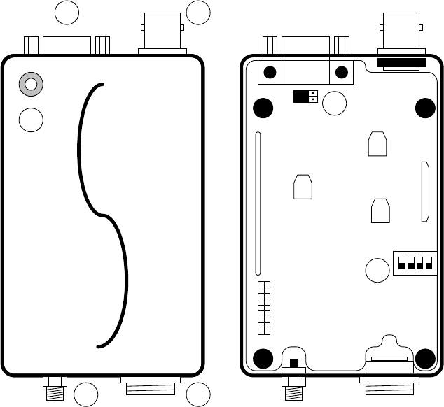
Description of radio components
Antenna connector
DB-15 connector
Power connector
GPS Antenna connector (option)
LED (Busy / Tx indicator)
7
Exterior View
RV402
RV401
SW401
maxon
RV403
CON407
12
34
5
7
6
Digital Board
Antenna installation
Fasten the antenna to the radio by turning the antenna cable clockwise into the receptacle on left of radio when looking at
front of radio.
Powering the data radio
Your data radio accepts many sources of DC power to permit more versatile use. This radio operates from 7.2V to 18V DC
and standard voltage for test is 12V DC.
Connecting the data radio to DC power
Connect DC power plug of power cable to radio’s DC IN power connector and then fasten power plug to the radio by
turning the ring clockwise.
8
SD-164 Operation
Channel select / SCAN
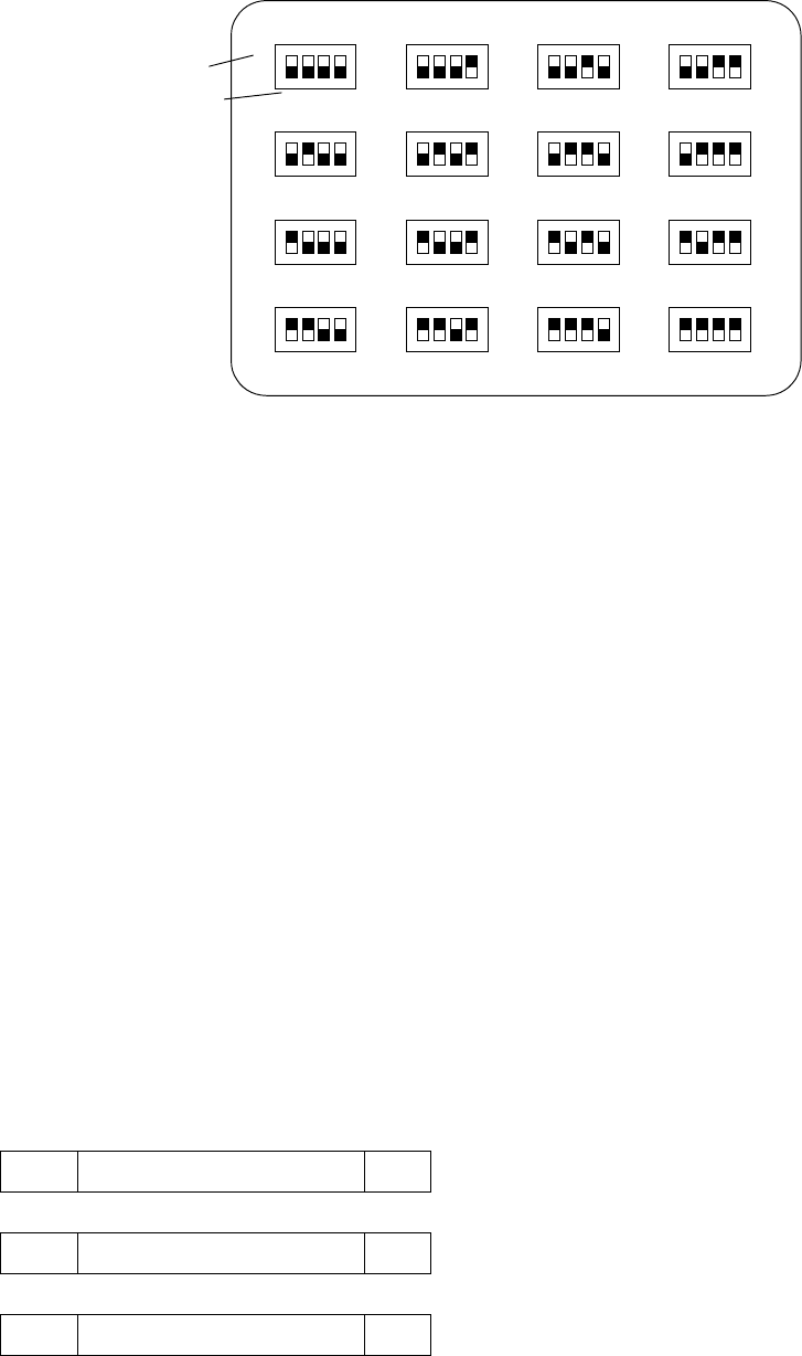
Your radio’s channel can be selected by inner DIP-S/W or serial command inputted from external control system. To
change channel by inner DIP-S/W (), you should open the upper cover and then look for DIP-S/W() on the digital
board of bottom cover. After that, change the DIP-S/W to select wanted channel according to channel dip switch chart.
To use serial command for channel selection, it should be inputted by external equipment or device(ex. Personal computer)
through Pin 8 of DB-15 connector. See the message format for serial command for full details.
If your radio has been programmed the channel scan, you must enter the scan mode by serial command.
Transmit
The transmission will be made by various inputs as like PTT signal (Pin 3 of DB-15 connector), TX serial command and
Serial data input (Pin 10 of DB-15 connector : This input is only available when modem option board is installed). Basically,
TTL level is used as PTT signal and it’s low active. But, If you installed option modem board, you can use RS-232 level as
PTT signal instead of TTL level. To maintain transmission, continuous PTT signal input is required. But, if you use Tx serial
command for transmission, normally, it’s released by Rx serial command. Before the transmission, check the color of the
radio’s top-panel LED(). It will glow orange if RF activity is present; it will not be illuminated if the radio indicates a “clear”
channel. When the channel is “clear”, input the PTT signal or Tx serial command and transmit data or audio. Remove the
PTT signal or input Rx serial command when you have finished transmission.
CAUTION : Operation of the transmitter without a proper antenna installed may
result in permanent damage to the radio.
Receive
When you have finished transmission, remove the PTT signal or input Rx serial command. You will receive data from
another radio or hear another person talking from the connected external speaker.
9
Scan modes
Scanning is a dealer programmable feature that allows you to monitor a number of channels. Your dealer will help you
define a scanning mode and your channel “scan list”
Channel scan
Once the scan list has been established, initiate scan by serial commands. If a conversation is detected on any of the
channels in the scan list, the radio will stop on that channel and you will be able to hear the conversation. At that time, busy
channel data is sent to external equipment or device through serial command. So, you can identify busy channel data as
decoding of received serial command from your radio in the external equipment or device.
Normally, if you try to transmit during scanning, the transmission will be made on the channel that the call was received
during the programmable scan delay time. (The scan delay time is the amount of time the radio will stay on that channel
once activity has ceased. In case of dealer programmable, 4 ~ 7 seconds is typical). The radio will resume scanning once
the scan delay time has expired, and will continue to scan until the serial command for scan stop is inputted by external
equipment. After the scan resumes, if a transmission is made, the radio will transmit on the selected priority channel. This
feature is similar to priority scan TX except for selection of priority channel. You can assign priority channel by inner dip
switch only.
Scan channel delete
To temporarily delete a channel from the scan list, simply input serial command for scan deletion to the radio while
scanning and stopped on the channel to be deleted. This will remove that channel from the scan list until the scan is closed
or the radio’s power is reset. When scan restarts after close one time, all scan list are deleted, start scan after turn off or
turn on the power of the radio, the originally programmed scan list will be activated.
CTCSS / DCS Scanning
To help to block out unwanted calls to your radio, the SD-160 series can be programmed by your dealer to scan for tones.
10
Channel dip switch chart
1 2 3 4 1 2 3 4 1 2 3 4 1 2 3 4
1 2 3 4 1 2 3 4 1 2 3 4 1 2 3 4
1 2 3 4 1 2 3 4 1 2 3 4 1 2 3 4
1 2 3 4 1 2 3 4 1 2 3 4 1 2 3 4
1
16
234
5678
9101112
151413
SW401
CHANNEL SELECT SWITCH
CHANNEL NO.
SWITCH POSITION
Serial command
Serial RX/TX Data Format
(1) Asynchronous Serial Data Transfer
(2) Baud Rate : 4,800 bit/sec
(3) Data Bit : 8bit , Non Parity
(4) Stop Bit : 1bit
(5) MSB first transmission
Each serial command is consist of 3 bytes.
1st byte is command and 2nd is data required by command and 3rd is check sum to decide validity of total contents.
Byte0
ST 1st Byte (Command) SP
Byte1
ST 2nd Byte (Data) SP
Byte2
ST 3rd Byte (Check Sum) SP
11
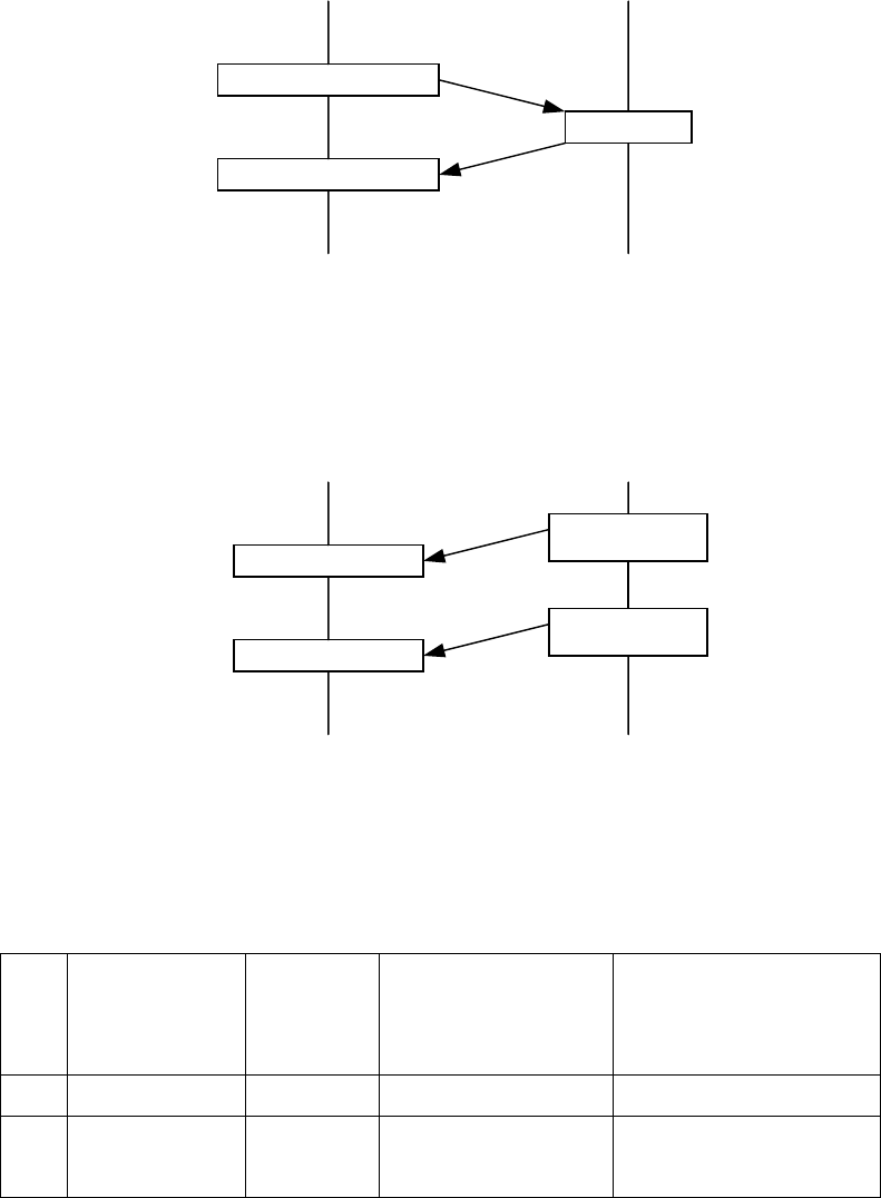
Data Protocol
Protocol for input Serial command
Protocol of data transmission from external equipment or device (: PC) to radio :
Input serial command
Receive response
Response
External equipment or device Radio
Protocol for output data
Protocol of data transmission from radio to external equipment or device (: PC) :
Receive Data
Receive Data
Output Data
(with command)
External equipment or device Radio
Output Data
(with command)
Serial Commands
Transmit Command & data
Mode Transmit
Command
(BYTE0)
Transmit data( BYTE1 ) Check sum( BYTE2 )
: Transmit Command + data
1. Channel Change 0x64 0x?? :Current channel ( 0x64 + Channel )
2. RTX Mode Send.
0x61 R(0x72) : Rx mode
T(0x74) : TX mode
( 0x61+0x72 )
( 0x61+ 0x74 )

12
From PC
To Radio
0x62 F(0x46) : Scan Stop
S(0x73) : Scan Start
O(0x4F) : Scan Delete
( 0x62+ 0x46 )
( 0x62+ 0x73 )
( 0x62+ 0x4F )
From
Radio
To Pc
0x66 0x00 : 1 Channel
0x01 : 2 Channel
0x02 : 3 Channel
0x0f : 16 Channel
0x66 + 0x00
0x66 + 0x01
*Only for Unmute Channel,
Correct Call Channel
3. Scan
Mode
Error
Message
0x65 It is occurred when Scan Delete command comes
except for Busy/Correct Call
It is occurred when PTT key is pushed except for
Busy/Correct Call.
It is occurred when channel change command exists
during Scanning.
4. GPS Initialize 0x63 0x00 : GPS Disable
0x01 : GPS Enable
( 0x63+ 0x00)
( 0x63+ 0x01)
5. Mode Entrance 0x60 0x01 0x60 + 0x01
Receive Command & data
Mode Transmit
Command
(BYTE0)
Transmit data ( BYTE1 ) Check sum( BYTE2 )
: Transmit Command + data
0xaa ACK 1 Process Complete
Commands 0x55 NACK
Note)
This command is return signal for receiving command.
If Byte2 and sum of Byte0 and Byte1 among received data are same, Radio would send ACK data and execute
command. If not, Radio sends Nack data.
User would go into next step if receives ACK data. If user receives Nack data, user should send command again.
example) If user changes from 1st Channel to 2nd Channel,
User should send Channel Change Command ( 0x64,0x02 , ( 0x64 + 0x2 ) ) to Radio.
If Byte2 and sum of Byte0 and Byte1 among received data are same, Radio sends ACK data to user and
changes to 2nd channel. If not, Radio would send Nack data.

13
Status indicators and audible alert tones
Your SD-160 series data radio has a sophisticated microprocessor control which provides a range of LED displays. LED
displays operation mode, current status of radio, warning, and etc. Moreover, if you connect Speaker filtered OUT (Pin 9 of
DB-15 connector) to the external speaker, you can hear audible tones at the following conditions:
• Attempt to transmit on a channel that is already in use when busy channel lockout has been programmed into the radio
• Transmission time has exceeded time-out timer programmed length
• When the other group or people finished transmission using repeater
See the status indicators and audible alert tones chart for full details.
STATUS DESCRIPTION LED COLOR AUDIBLE TONE
POWER ON -
Busy Channel Yellow
Correct Call Green
Transmit Yellow
NORMAL
Transmit Not Allowed
Normal Scan Mode Green LED Flash
Scan Delete one times Red LED
SCANNING
Scan All Delete Two times Red LED
Busy Channel lockout two times Green LED Single Beep Tone
Time out Time one times Green LED
Before 5S T-O-T one times Green LED Single Beep Tone
EEPROM Error one times Yellow LED
Unlock Four times Yellow LED
Communication error with
Modem MCU
Green LED flash
Transmit Hang on time - Single Beep Tone
WARNING
At transmission, if Audio
sound is not heard or
Modem is not placed
Two times Green LED

14
Read Mode Red LED flash
PROGRAM
Write Mode Green LED flash
AUTO TEST Yellow
Open Squelch Mode three times Green LED
Close Squelch Mode Two times Green LED
Save Squelch Mode One times Green LED
SQUELCH PROGRAM
MODE
Init Data Load one times Green LED

15
DB 15 PIN descriptions with input/output level
D-Type
Pin No.
Function Description Signal Type Input/
Output
1 Data modulation IN
(Tx Mod)
Signal is directly injected to MOD through data
low pass filter without pre-emphasis.
Analog signal
1KHz audio at 60%
peak system deviation
input level =
100 to 120mVrms
I/P
2 Data unfiltered OUT
(RX disc)
Discriminator audio from the SD-160. This is
the unprocessed AF signal prior to tone
filtering and de-emphasis.
Analog signal
1KHz audio at 60%
peak system deviation
produces
200 to 300mVrms
O/P
3 PTT In
(Tx Key)
Signal from the ‘external device’ to key the
SD-160 transmitter.
This line has an internal pull up resistor to +5V.
Pulling the line to 0V turns on the transmitter.
Note : If you installed option modem board,
you can select RS-232 signal level by
Jumper (CON407, ) on the digital board.
TTL level
0V = Tx
o/c = Rx
RS-232 level (option)
+12V = Tx
-12V = Rx
I/P
4 Ground Ground connection to chassis of the radio. 0V (Chassis)
5 Serial Data Out
(TXD)
Serial data output for radio control or program.
It uses asynchronous data format.
TTL level O/P
6 Busy
(CD)
Logic level output from SD-160 to indicate
whether a carrier is present or not
Note : If you installed option modem board,
you can select RS-232 signal level by
Jumper (CON407, ) on the digital board.
TTL level
0V = carrier
5V = no carrier
RS-232 level (option)
+12V = carrier
-12V = no carrier
O/P
7 Microphone filtered
audio IN
This signal is injected to the MOD at the point
through audio-amplification, pre-emphasis and
high pass filtering where sub-audio tone is
mixed with audio.
Audio
1KHz audio at 60%
peak system deviation
input level =
6 to 8Vrms
I/P

16
8 Serial data IN
(RXD)
Serial command or data input for radio control
or program. It uses asynchronous data format.
TTL level I/P
9 Speaker filtered OUT Audio output from the audio amplifier.
It’s filtered by tone-filter, de-emphasis circuit.
Audio
1KHz audio at 60%
peak system deviation
produces Nominal
1Vrms @ 8Ω
O/P
10 Serial data IN for
option modem
The Serial data to be transmitted is input to
this pin. It’s only available when option modem
board is installed. Inputted data are modulated
by modem IC and then injected to MOD.
It uses asynchronous data format.
RS-232 level I/P
11 Serial data Out for
option modem
The recovered asynchronous serial data
output from the receiver. It’s only available
when option modem board is installed. It uses
asynchronous data format.
RS-232 level O/P
12 Serial data busy for
option modem
(reserved)
To eliminate data loss according to buffer
overrun of slave MCU’s memory, it indicates
buffer status.
RS-232 level O/P
13 GPS data input Data input for initial setting of GPS module.
It follows NMEA 0183 format and uses
asynchronous data format.
TTL level I/P
14 DGPS data input Data input for DGPS Correction of GPS
module. It follows NMEA 0183 format and
uses asynchronous data format.
TTL level I/P
15 GPS data output Position data output from the GPS module. It
follows NMEA 0183 format and uses
asynchronous data format.
TTL level O/P

17
Modem for data communication
Descriptions
A new kinds of internal Option-Modem are applied to SD-160 series. One is FFSK modem and the other is GMSK modem.
The most obvious method of increasing the efficiency is to maximize the data signaling speed in the limited channel
bandwidth. But, FSK has very wide transmission bandwidth requirement. To solve this problem, we will supply GMSK
(Gaussian Filtered Minimum Shift Keying) internal option-board.
In the case of data, its frequency spectra conflict with sub-audio frequency spectra. So tone squelch system is not
adaptable. If there is tone, only FFSK / MSK modem available and no GMSK modem is used.
Our internal Modem Option Boards consist of Slave MCU, Modem IC, and extra circuitry. This Option-Boards directly
communicates with DTE (Data Terminal Equipment) to send and receive the meaningful data through the D-sub connector.
Communication between DTE and Option-Board
These modem option boards support only asynchronous communication between DTE and modem option boards to
minimize loss of data during the transmission.
Your dealer will help you define a TX On/Off Delay time, RX On Delay time, Baud Rate, Modem Enabled, Modem Baud
Rate, RTS Control Mode, and Test Mode.
Chart for modem speed
Data transmission speed for FFSK Modem
UART Baud Rate
of DTE (BPS) Channel Space Modem Baud Rate
(BPS)
Narrow (12.5KHz) 1200
1200
Standard (25KHz) 1200
Narrow (12.5KHz) 2400
2400
Standard (25KHz) 2400
4800 Standard (25KHz) 4800

18
Data transmission speed for GMSK Modem
UART Baud Rate
of DTE (BPS)
Channel Space Modem Baud Rate
(BPS)
Narrow (12.5KHz) 4800
4800
Standard (25KHz) 4800
9600 Standard (25KHz) 9600
Transmission GPS Data through Modem
If GPS option board is installed in SD-160 series data radio, you can obtain your position data through GPS data output of
your radio (Pin 15 of DB-15 connector). Besides, you can transmit received GPS data to the other radio or base station
through modem if you install modem board with GPS board.
Your dealer will help you install GPS option board and define related parameter set-up.

19
Option board pin-out chart
FFSK Modem Option board
Connector
No.
Pin
No. Function Description
Input/
Output
1 VCC 6V to 12V Power Input I/P
2 GND Ground
3 PTT Signal from the digital board to transmit data key the SD-
160 transmitter I/P
4 TXD_EN It ensures that the radio has stabilized in transmission
before the data is processed for modulation. I/P
5 TX_END To finish transmission, it indicates memory buffer of Master
MCU of digital board is empty. O/P
6 MUTE
(Busy)
Logic level input from digital board to indicate whether a
carrier is present or not I/P
7 CORRECT_CALL It indicates that received signal has wanted tone or code if
you apply tone squelch. I/P
8 POWER_SAVE Power save input for modem board. I/P
9 CMD_EN It indicates that command for Modem programming is
effective. I/P
10 CMD_IN/OUT Data Input and Output for Modem programming. I/P,
O/P
11 CMD_CLK Clock Input for Modem programming. I/P
12 MODEM_SEL It Indicates modem type to Master MCU for programming. O/P
13 RX_IN The FFSK/MSK signal input for the receiver of modem IC. I/P
Connector 1
14 TX_OUT The FFSK/MSK signal output when the transmitter is
enabled. O/P
1 Serial_IN The Serial data to be transmitted is input to this pin. I/P
2 Serial_OUT The recovered asynchronous serial data output from the
receiver. O/P
Connector 2
3 Busy To eliminate data loss according to buffer overrun of slave
MCU’s memory, it indicates buffer status. O/P

20
4 Carrier_Detect Handshake signal for RTS control mode. It indicates
whether Slave MCU of modem has decoded data or not. O/P
5 PTT_IN Handshake signal for RTS control mode. It requests data
transmission to Slave MCU of modem. I/P
6 PROGRAM It’s reserved input for firmware upgrade. I/P
GMSK Modem Option board
Connector
No.
Pin
No. Function Description
Input/
Output
1 VCC 6V to 12V Power Input I/P
2 GND Ground
3 PTT Signal from the digital board to enable transmitter circuit of
modem board. I/P
4 TXD_EN It ensures that the radio has stabilized in transmission
before the data is processed for modulation. I/P
5 TX_END To finish transmission, it indicates memory buffer of Master
MCU of digital board is empty. O/P
6 MUTE
(Busy)
Logic level input from digital board to indicate whether a
carrier is present or not I/P
7 N/C Not Connected
8 POWER_SAVE Power save input for modem board. I/P
9 CMD_EN It indicates that command for Modem programming is
effective. I/P
10 CMD_IN/OUT Data Input and Output for Modem programming. I/P,
O/P
11 CMD_CLK Clock Input for Modem programming. I/P
12 MODEM_SEL It Indicates modem type to Master MCU for programming. O/P
13 RX_IN The GMSK signal input for the receiver of modem IC. I/P
Connector 1
14 TX_OUT The GMSK filtered Tx output signal. O/P
1 Serial_IN The Serial data to be transmitted is input to this pin. I/P Connector 2
2 Serial_OUT The recovered asynchronous serial data output from the
receiver. O/P

21
3 Busy To eliminate data loss according to buffer overrun of slave
MCU’s memory, it indicates buffer status. O/P
4 Carrier_Detect Handshake signal for RTS control mode. It indicates
whether Slave MCU of modem has decoded data or not. O/P
5 PTT_IN Handshake signal for RTS control mode. It requests data
transmission to Slave MCU of modem. I/P
6 PROGRAM It’s reserved input for firmware upgrade. I/P
GPS Option board
Pin
No. Function Description
Input/
Output
1 VCC 6V to 12V Power Input I/P
2 VBAT
3 ENABLE I/P
4 PSAVE I/P
5 GND Ground
6 GPS_OUT I/P
7 DGPS_IN
8 GPS_IN I/P
9 +5V I/P
22
Compatible accessory list
ACC-513 9600 baud GMSK modem
ACC-514 4800 baud FFSK modem
ACC-515 GPS receiver
ACC-160 GPS antenna
ACC-516 PCB Interface - used to separate digital and RF board for alignment.
ACC-916 Personality programming software.
ACC-2016 Individual programming cable
ACC-2160 Test jig box