Midland Radio SD225U1 UHF DATA RADIO User Manual UG SD225
Midland Radio Corporation UHF DATA RADIO UG SD225
UserManual.wiki
>
Midland Radio
>
SD225U1 User Manual
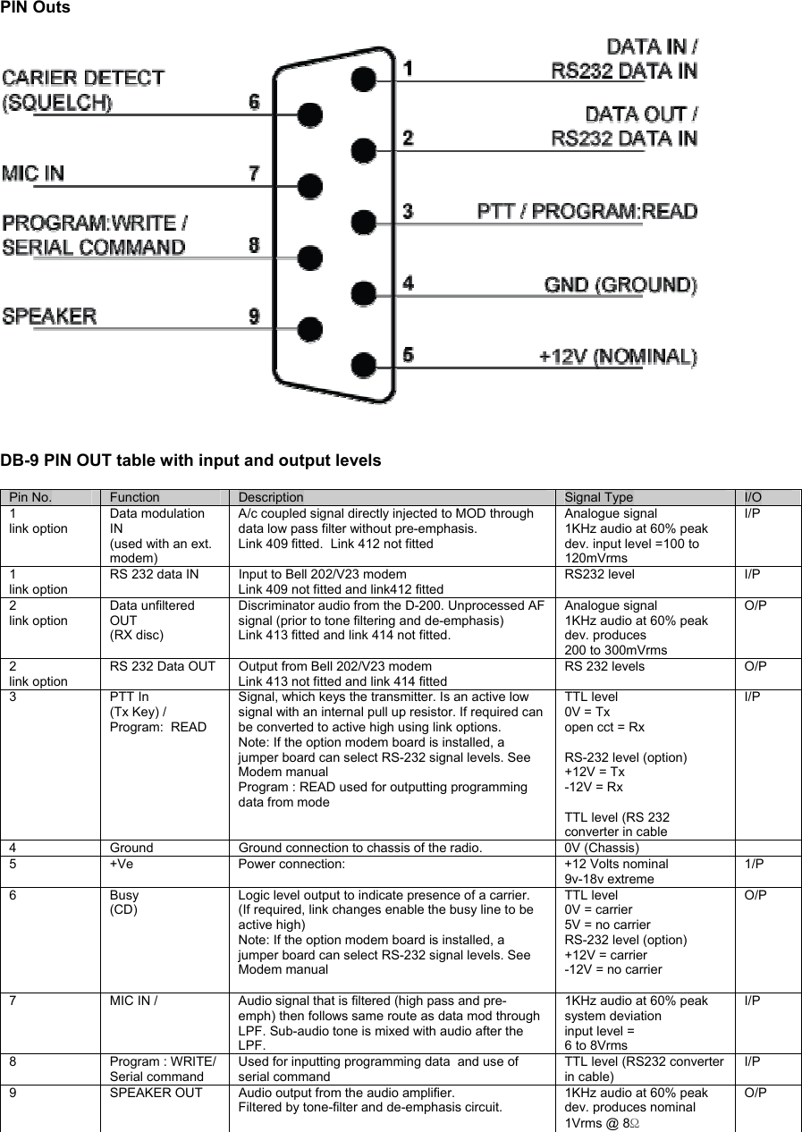
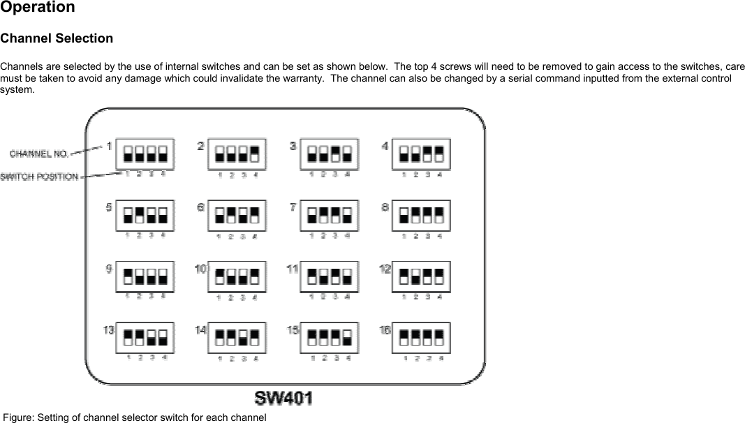
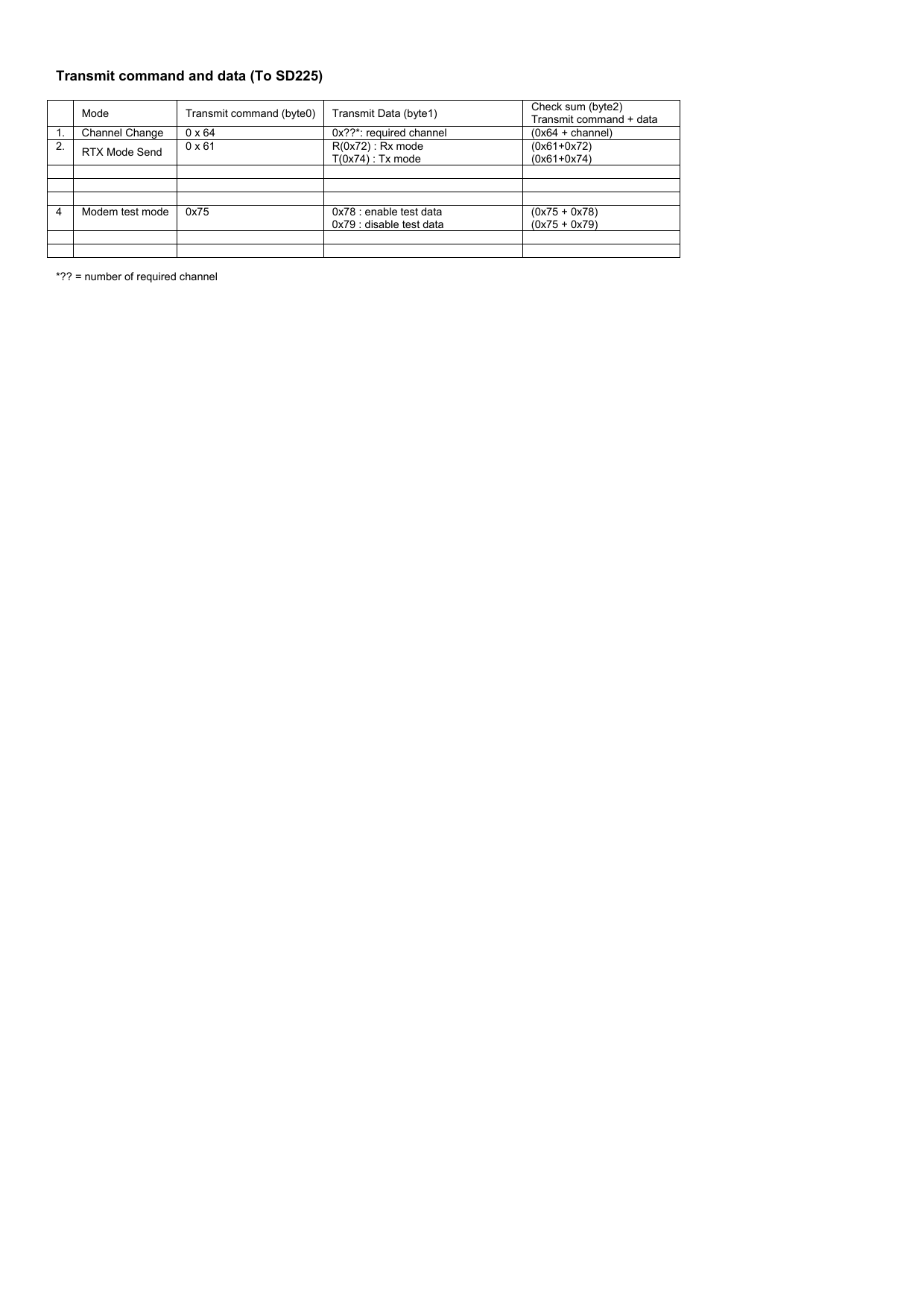
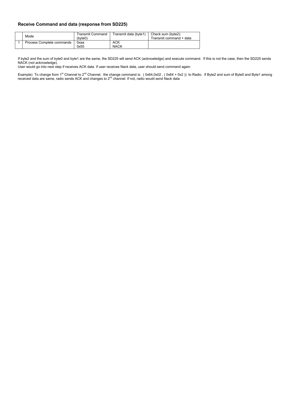
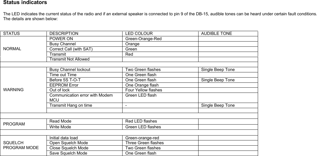
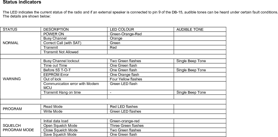
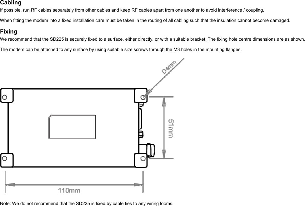
USERS MANUAL
Navigation menu
Upload a User Manual
Namespaces
Wiki Guide
HTML
PDF
Info
Views
User Manual
Discussion / Help
Navigation