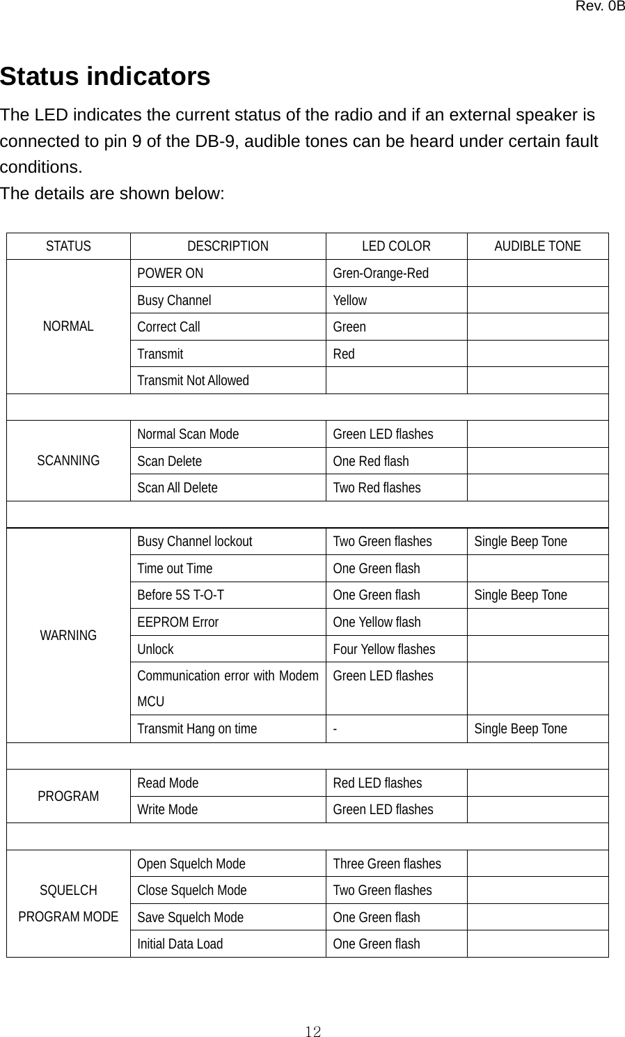
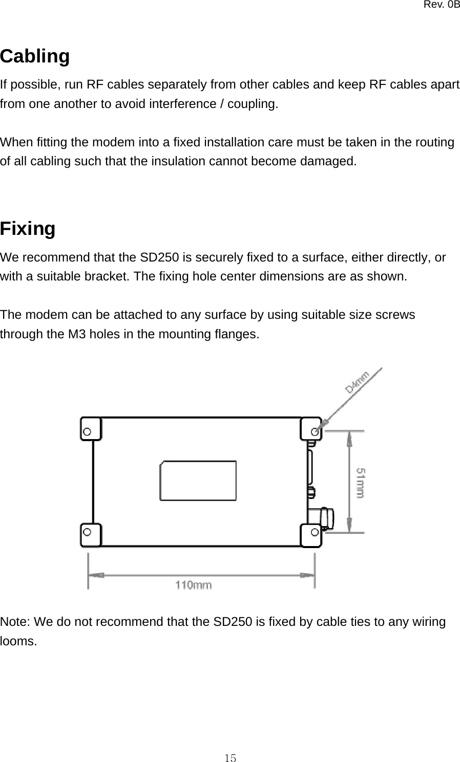
Midland Radio SD250V2 VHF Data Radio User Manual Preliminary UG SD250 0B

Midland Radio Corporation VHF Data Radio Preliminary UG SD250 0B

Users Manual

  SD-250 User Guide
Rev. 0B   1Contents  Introduction --- 2 Preparing for use Unpacking and inspection --- 3 Description of modem --- 4 Features --- 5 External Connections --- 6 Pin Outs --- 7 Operation Channel Selection --- 9 Transmit/Receive Operation --- 10 Serial Commands --- 10 Status Indicators --- 12 Programming --- 13 Installation Antennas --- 14 Power sources --- 14 Cabling --- 15 Fixing --- 15 Safety and general information --- 16 Warranty and repairs --- 18 Care of the equipment --- 18 Disposal / Recycling --- 18
Rev. 0B   2Introduction  The SD250 range is a 1 to 6 Watts RF data module at VHF and UHF frequencies.  The SD250 is housed in a rugged cast-aluminum box sealed to IEC 529 (IP54) making it suitable for a wide range of mobile and fixed applications.  All SD250 RF data module units meet the essential requirements of the relevant directives. In order to maintain this compliance the installation and safety information must be adhered to at all times.  • The SD250 RF data module must only be installed where unintentional contact cannot be made. The surface of the device may be hot to touch under certain transmit conditions. The SD250 is not designed for permanent transmission. If prolonged transmission periods are used, the unit will become hot and will require an additional heat-sink to be fitted.  • When fitting the module into a fixed installation, care must be taken in the routing of all cabling such that the insulation cannot become damaged.  • The recommended supply sources for use with the SD250 is a standard 12V / 2A dc supply, but is capable of operating in the range 9V - 18V.
Rev. 0B   3Preparing for use  Unpacking and inspection Unpack the modem and check that you have received the following items: • SD250 RF data module • User Guide (this document)  If any of these items are missing, please contact your supplier.
Rev. 0B   4Description of modem  The SD250 is a network free, point to point RF data module that offers great flexibility in varied applications where wireless data or voice communication is needed. It can be used as a transparent radio, with no internal modem fitted, to allow users to facilitate the use of their own modem and protocol. The correct signal levels need to be used with the use of separate control lines, see the pin out table below.  The SD250 can also be fitted with below a few different modems  • Bell 202 / V.23 modem (1200 baud rate) • FFSK modem (4800 baud rate) • GMSK modem (9600 baud rate)  The internal modem allows communication with a pc using RS 232 for the data and control lines. For further details, please refer to the modem manual.  SD250 has standard radio features available which are associated with a private radio. This includes CTCSS and DCS, software controlled squelch, time out timer options and busy channel lockout as listed below (not all available with option modem fitted). There is a microphone input and speaker output to allow speech to be transmitted and received.
Rev. 0B   5Features  • Compact and rugged die cast box • Resistant to dirt, dust and water ingress (IP54 rated) • Network free, point to point communication • 1 / 6 watt programmable output power • Synthesized operation with 16 channel capability • SAT when used with Bell 202 / V.23 and FFSK modem or speech • Programmable 12.5 / 25kHz channel spacing • External modem / Direct FM • Internal modem options available: Bell 202 / V.23, FFSK, GMSK • ‘Busy’ output (can be set active high or low) • 9 – 18 volt supply input • Busy Channel lockout • Time out timer
Rev. 0B   6External Connections     1. HD 9-way d-type (data, control signals and power supply) 2. BNC antenna connector
Rev. 0B   7Pin Outs 1596Busy DetectMic InputProg. Data InputSpeaker OutputMod. Input (Data)Demod. Output (Data)PTT / Prog. Data OutputGNDB+ DB-9 PIN OUT table with input and output levels D-Type Pin No.  Function Description  Signal Type  Input/ Output Data modulation IN (Tx Mod)   Default : AC coupled signal directly injected to MOD through data low pass filter without pre-emphasis.  Direct Modulation(includes POCSAG) : DC coupled signal directly injected to MOD. No data filter and pre-emphasis on signal path. Direct FM MOD. is selected by PC program. Link 409 fitted. Link 412 not fitted.  Default : Analog signal  1KHz audio at 60% peak system deviation input level = 100 to 120mVrms  Direct FM : TTL level 1 RS 232 data IN  Input to Bell 202/V23, FFSK, GMSK modem. Link 409 not fitted and link412 fitted.  RS-232 level (option) +12V = Tx -12V = Rx I/P Data unfiltered OUT (RX disc)  Discriminator audio from the SD-250. This is the unprocessed AF signal prior to tone filtering and de-emphasis. Link 413 fitted and link 414 not fitted. Analog signal 1KHz audio at 60% peak system deviation produces  200 to 300mVrms 2 RS 232 data OUT  Output from Bell 202/V23, FFSK, GMSK modem. Link 413 not fitted and link 414 fitted RS-232 level (option) +12V = Tx -12V = Rx O/P 3  PTT In (Tx Key)  /  Signal, which keys the transmitter, is an active low input with an internal pull up resistor. If required, the pin can be converted to active high using link options. TTL level 0V = Tx o/c = Rx  I/P  /
Rev. 0B   8Program: Read  Note: If the option modem board is installed, a resistor link can select RS-232 signal levels. See Modem manual Program : READ used for outputting programming data from mode RS-232 level (option) +12V = Tx -12V = Rx TTL level only for radio program O/P 4  Ground  Ground connection to chassis of the radio.  0V (Chassis)   5  B+  Power supply input (Nominal 12V)  9.0V – 18.0V DC   6 Busy (CD)  Logic level output to indicate presence of a carrier. (If required, link changes enable the busy line to be active high) Note: If the option modem board is installed, a resistor link can select RS-232 signal levels. See Modem manual.   TTL level 0V = carrier 5V = no carrier  RS-232 level (option) +12V = carrier -12V = no carrier O/P 7 Microphone filtered audio IN  Audio signal that is filtered (high pass and pre-emphasis) then follows same route as data mod through LPF. Sub-audio tone is mixed with audio after the LPF. Audio 1KHz audio at 60% peak system deviation input level = 6 to 8Vrms I/P 8  Program: Write / Serial command  Used for inputting programming data and use of serial command.  TTL level  I/P 9 Speaker filtered OUT  Audio output from the audio amplifier. Filtered by tone-filter and de-emphasis circuit. 1KHz audio at 60% peak dev. produces Nominal 1Vrms @ 8Ω O/P
Rev. 0B   9Operation  Channel Selection Channels are selected by the use of internal switches and can be set as shown below. The top 4 screws will need to be removed to gain access to the switches, care must be taken to avoid any damage which could invalidate the warranty. The channel can also be changed by a serial command inputted from the external control system.   1    2    3    4 1    2    3    4 1    2    3    4 1    2    3    41    2    3    4 1    2    3    4 1    2    3    4 1    2    3    41    2    3    4 1    2    3    4 1    2    3    4 1    2    3    41    2    3    4 1    2    3    4 1    2    3    4 1    2    3    411623456789101112151413CHANNEL NO.SWITCH POSITION  Figure: Setting of channel selector switch for each channel
Rev. 0B   10Transmit/Receive Operation  The SD250 is put into transmit/receive either by using TTL levels, RS 232 levels or serial command, depending on the application and modem set up.  When the radio is used with no internal modem, TTL levels (pin 3 on DB9) can be used. The default condition is active low for transmit, and active high, or not connected, for receive. It is possible to alter the polarity of this control signal by adding components, refer to the pin out table for details.  If an internal modem is fitted the levels used need to be RS232 and a resistor link needs to be incorporated in the correct position to allow correct operation, see modem manual.  The TX serial command (see later for further details) can also put the radio into transmit, until the RX serial command is received (pin 8 of DB9).  Serial Commands  The RF data module can be controlled by using the serial command (pin 8) , sending commands to the radio such as PTT or change channel  The format for these commands (asynchronous) are:  • baud rate: 9600 bit/sec • Data Bit: 8 bit, non parity • Stop Bit: 1 bit • MSB first transmission  Each serial command consists of 3 bytes. The first byte is the command, the second is data required by the command and the third is the check sum to validate contents
Rev. 0B   11    Byte0 Start bit  1st 8-Bits (Command)  Stop bit     Byte1 Start bit  2nd 8-Bits (Data)  Stop bit     Byte2 Start bit  3rd 8-Bits (Check Sum)  Stop bit   Available Command and Data format  Mode  Command (1st 8-Bits) Data ( 2nd 8-Bits) Check sum ( 3rd 8-Bits ) : Command + Data 1.  Channel Change  0x64  0xXX :Current channel  ( 0x64 + Channel ) 2.  RTX Mode Selection  0x61  R(0x72) : Rx mode T(0x74) : TX mode ( 0x61+ 0x72 ) ( 0x61+ 0x74 ) 3.  Modem test mode  0x75  0x78 : Enable test data 0x79 : Disable test data ( 0x75 + 0x78 ) ( 0x75 + 0x79 ) GMSK  0x7a  0x00 : Disable 0x01 : Enable ( 0x7a + 0x00 ) ( 0x7a + 0x01 ) 0x7c  0x00 : Disable 0x01 : Enable Mark data ( 0x7c + 0x00 ) ( 0x7c + 0x01 ) 4. Modem alignment mode FFSK & AFSK 0x7e  0x00 : Disable 0x01 : Enable Space data ( 0x7e + 0x00 ) ( 0x7e + 0x01 ) 5.  Radio Reset  0x86  0x01  ( 0x86 + 0x01 )  example)    In order to change channel from 1 to 2,   0x64, 0x02, ( 0x64 + 0x2 ) should be applied to Radio in order.  Note) To clear memory buffer for serial command in Micro-controller, its 3 bytes buffer should be filled up. On getting 3 consecutive bytes, MCU automatically decides its correct action and then clear its memory immediately.
Rev. 0B   12Status indicators The LED indicates the current status of the radio and if an external speaker is connected to pin 9 of the DB-9, audible tones can be heard under certain fault conditions. The details are shown below:  STATUS DESCRIPTION LED COLOR AUDIBLE TONE POWER ON  Gren-Orange-Red   Busy Channel  Yellow   Correct Call  Green   Transmit Red  NORMAL Transmit Not Allowed      Normal Scan Mode  Green LED flashes   Scan Delete    One Red flash   SCANNING Scan All Delete  Two Red flashes    Busy Channel lockout  Two Green flashes  Single Beep Tone   Time out Time  One Green flash   Before 5S T-O-T  One Green flash  Single Beep Tone   EEPROM Error  One Yellow flash   Unlock Four Yellow flashes  Communication error with Modem MCU Green LED flashes   WARNING Transmit Hang on time    -  Single Beep Tone    Read Mode  Red LED flashes     PROGRAM  Write Mode  Green LED flashes    Open Squelch Mode  Three Green flashes   Close Squelch Mode  Two Green flashes   Save Squelch Mode  One Green flash   SQUELCH PROGRAM MODE Initial Data Load    One Green flash
Rev. 0B   13Programming  The data modem is a pc programmable modem. The parameters available for programming include:  • Frequency, channel spacing and sub-audible tones on a per channel basis • Standard radio settings such as power save mode, scan, tx lockout, tx timeout • Squelch enable • Modem options when the Bell 202 / V.23, FFSK, GMSK is fitted, such as data settings (flow control, block size etc) and timings.  The pc program also allows for squelch adjustments and calibration
Rev. 0B   14Installation  Antennas It is important that any antennas are installed in a suitable location with an adequate ground plane. Ideally, multiple antennas should be separated by a minimum of a wavelength (at the lowest frequency), whilst still retaining a good ground plane for each antenna. Therefore, for a 400MHz system, the ideal separation should be a minimum of 0.75m, and for 150MHz system the minimum should be 2.5m.  Warning: If installing an antenna near people it is necessary to ensure the minimum separation is maintained. This particularly important where prolonged exposure is likely.  Power sources It is important that a “clean” source of power is used for the 12V supply to the modem
Rev. 0B   15Cabling If possible, run RF cables separately from other cables and keep RF cables apart from one another to avoid interference / coupling.  When fitting the modem into a fixed installation care must be taken in the routing of all cabling such that the insulation cannot become damaged.  Fixing We recommend that the SD250 is securely fixed to a surface, either directly, or with a suitable bracket. The fixing hole center dimensions are as shown.  The modem can be attached to any surface by using suitable size screws through the M3 holes in the mounting flanges.    Note: We do not recommend that the SD250 is fixed by cable ties to any wiring looms.
Rev. 0B   16Safety and general information  Important information on safe and efficient use of your Radio device   Exposure to radio frequency energy Your modem is a high power radio transceiver. When it is on, it receives and also sends out radio frequency (RF) signals. To help minimize human exposure to RF electromagnetic energy, keep transmission time to 50% or less. As with all radio devices, holding the antenna affects transmission quality and may cause the radio to operate at a higher power level than required. Do not hold the antenna when the radio is in use. Do not use radios with damaged or modified antenna, this may violate compliance with relevant international standards. Where prolonged human exposure is likely, the minimum separation from the antenna should be 0.8m.  Electromagnetic interference/compatibility Most modern electronic equipment is shielded from RF energy. However certain electronic equipment may not be shielded against RF signals. The modem needs to be switched off in any facility where posted notices instruct you to do so to avoid electromagnetic interference or compatibility conflicts. Special care should be taken near facilities such as hospitals or health care centers may be using equipment that is sensitive to external RF energy.  Medical devices (Pacemakers) If you use any personal medical device, consult the manufacturer of your device to determine it is adequately shielded from RF energy. Your physician may be able to assist you in obtaining this information.
Rev. 0B   17Vehicles with airbags Air bags inflate with great force. Do not place a radio in the area over an airbag or in the airbag deployment area, any radio may be propelled with great force and cause serious injury to the occupant of the vehicle.  Potentially explosive atmospheres Turn off your modem prior to entering any area with a potentially explosive atmosphere, unless it is a radio type especially qualified for use in such areas. Do not remove install or charge batteries in such areas. Sparks in potentially explosive atmospheres can cause an explosion or fire resulting in bodily injury or death. Potentially explosive atmospheres include fuelling areas such as petrol stations, below decks on boats, fuel or chemical transfer or storage facilities, vehicles using liquid petroleum gas (such as propane or butane); areas where the air contains chemicals or particles such as grain, dust or metal powders, and any other area where you would normally be advised to turn off your vehicle engine. Areas with potentially explosive atmospheres are often but not always posted.
Rev. 0B   18Warranty and repairs The SD250 is a low maintenance device. Once installed it requires no ongoing maintenance. In the event that your SD250 RF data module needs repair, return your radio to an authorized Midland Radio supplier. Do not disassemble, modify or repair the unit unless the work is carried out by a Midland Radio approved supplier. Incorrect assembly, modification or repair may cause irreparable damage to your unit and will invalidate any warranty.  Care of the equipment Do not immerse the SD250 RF data module in water or other fluids. Do not use solvents or spirits for cleaning as this may cause damage to the case materials. Do not over tighten connection to the modem.  Disposal / Recycling The SD250 is a Class 3 product in accordance with the Waste of Electrical and Electronic Equipment (WEEE) Directive. Disposal of this class of equipment must be carried out through an authorized recycling centre or contact your supplier. FCC warnings:
Rev. 0B   19Published by Midland Radio Corp. Any queries regarding information in this manual, please contact the Technical Services Group Leader at the above address. Information provided in this document is believed correct at time of printing but is subject to change without notice. Midland Radio will not accept liability for any loss, damage or costs howsoever caused as a result of the information provided.

Navigation menu