Midland Radio SP440 UHF HANDHELD TRANSCEIVER User Manual 1767AUT4 UserMan
Midland Radio Corporation UHF HANDHELD TRANSCEIVER 1767AUT4 UserMan
UserManual.wiki
>
Midland Radio
>
SP440 User Manual
USERS MANUAL
Navigation menu
Upload a User Manual
Namespaces
Wiki Guide
HTML
PDF
Info
Views
User Manual
Discussion / Help
Navigation
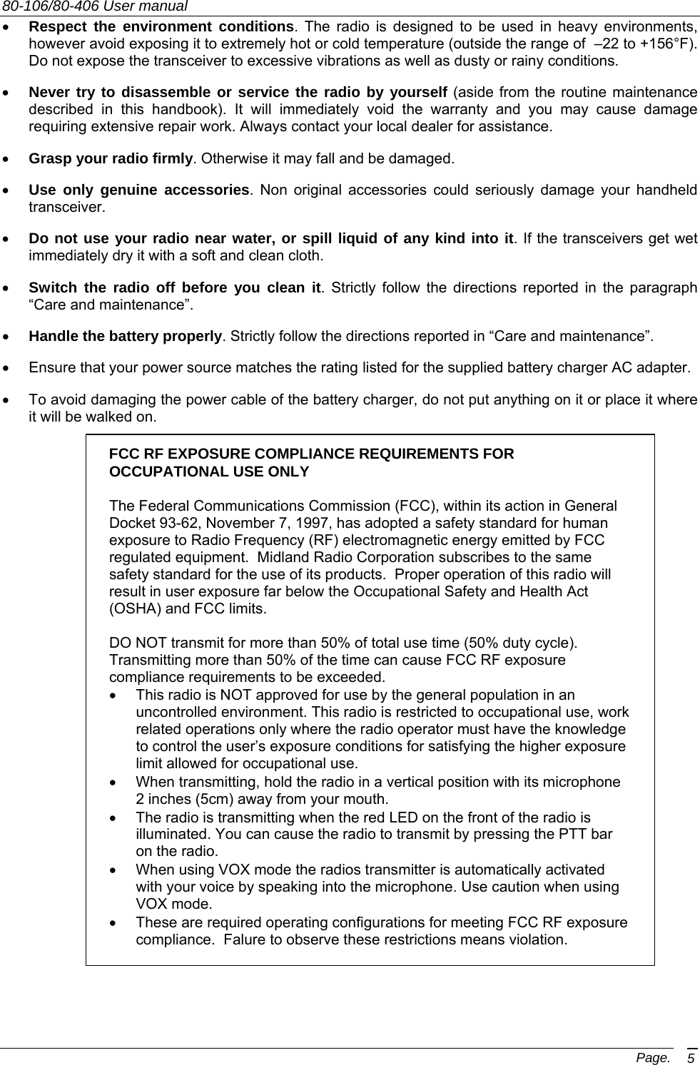
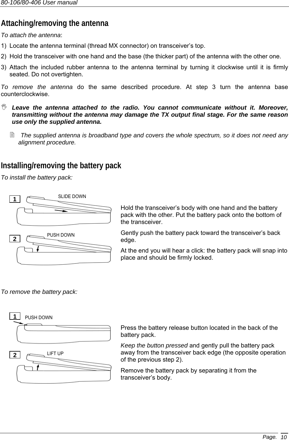
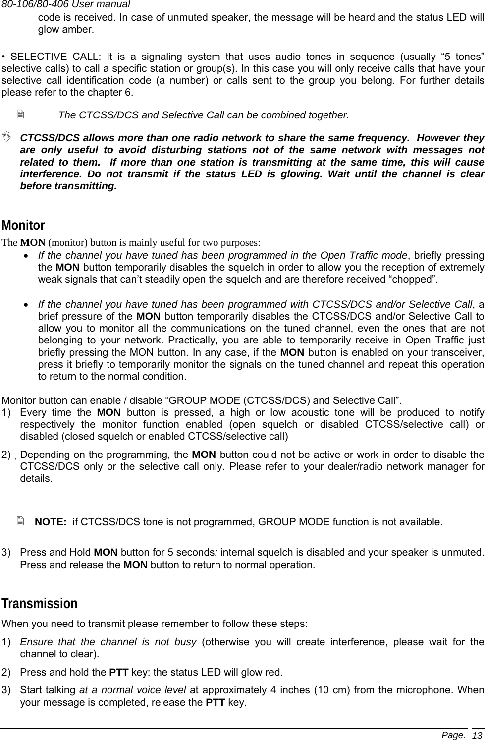
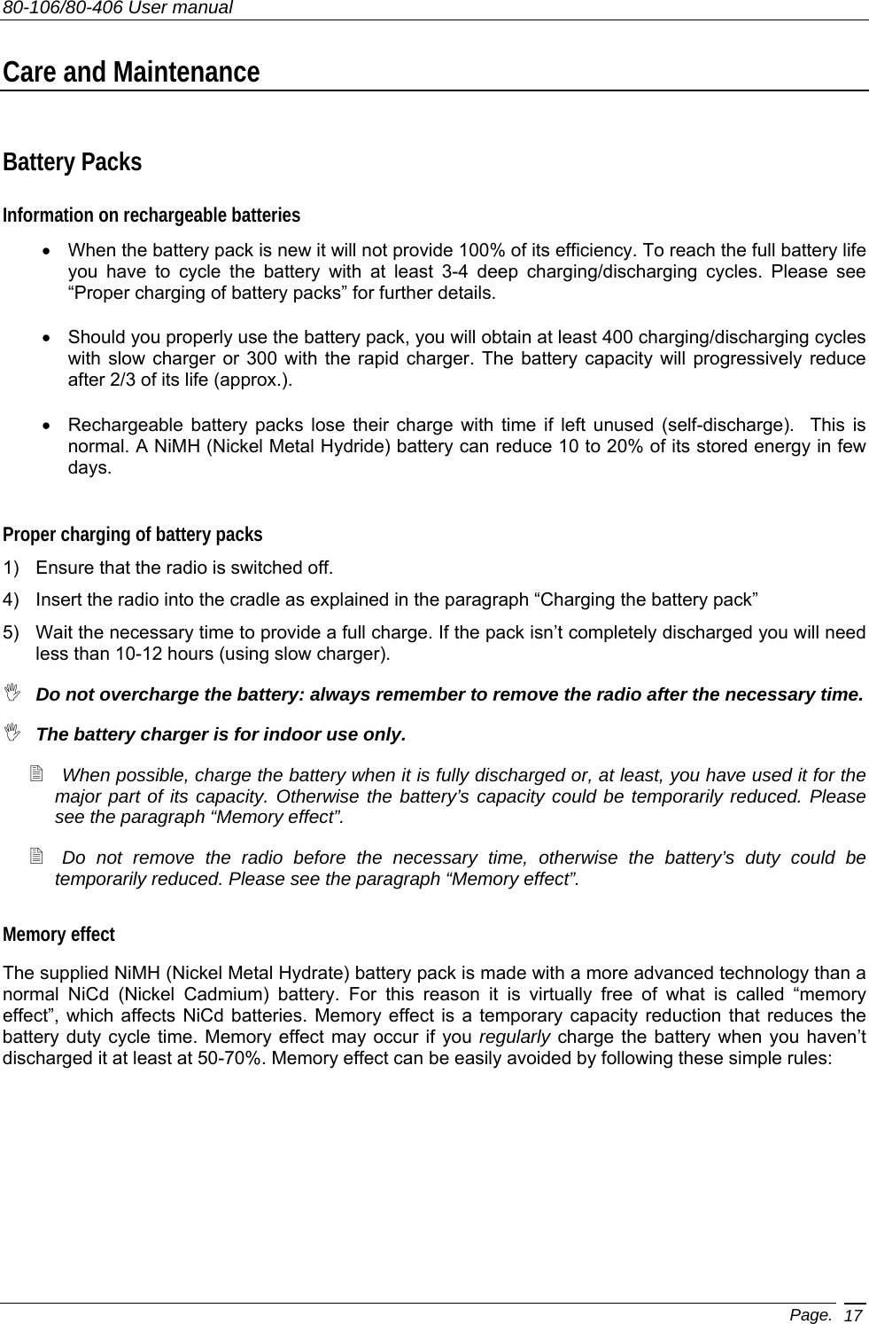
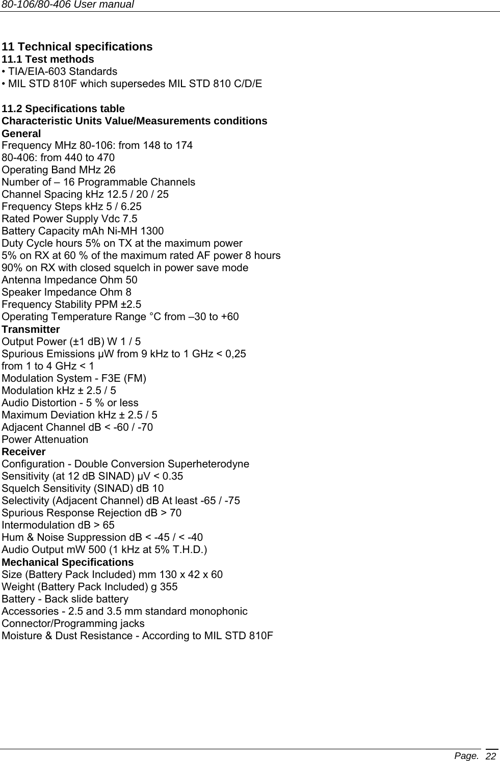
![80-106/80-406 User manual Page. 7 Part Names and their functions The following parts description will familiarize you with the transceiver’s main parts and controls. Numbers in brackets refer to the illustration. Top [1] Antenna connector. Attach the antenna to this connector (MX thread type). [2] Power ON/OFF knob. Rotate this knob to turn the transceiver on and off. [3] Channel selector knob. Rotate this knob to select the operating channel. [4] Status LED. Glows in different colors to show the current radio’s status. Front [5] Speaker. The built in speaker located in this area emits the received audio. [6] Microphone. The microphone located here detects your voice. 1 24 3](https://usermanual.wiki/Midland-Radio/SP440/User-Guide-491232-Page-7.png)
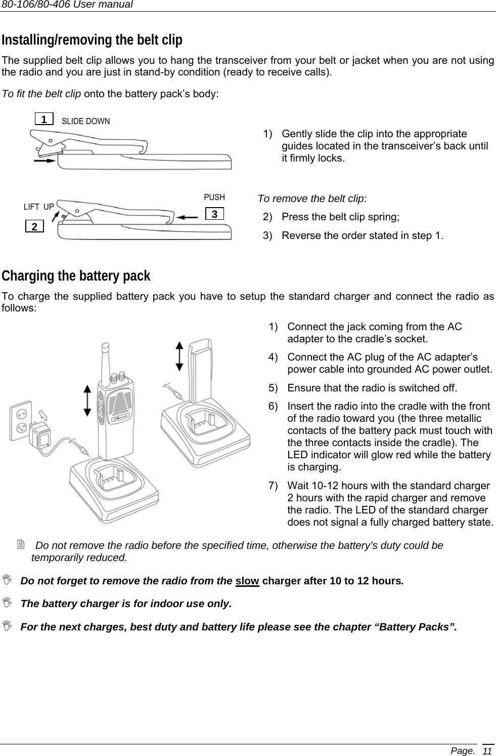
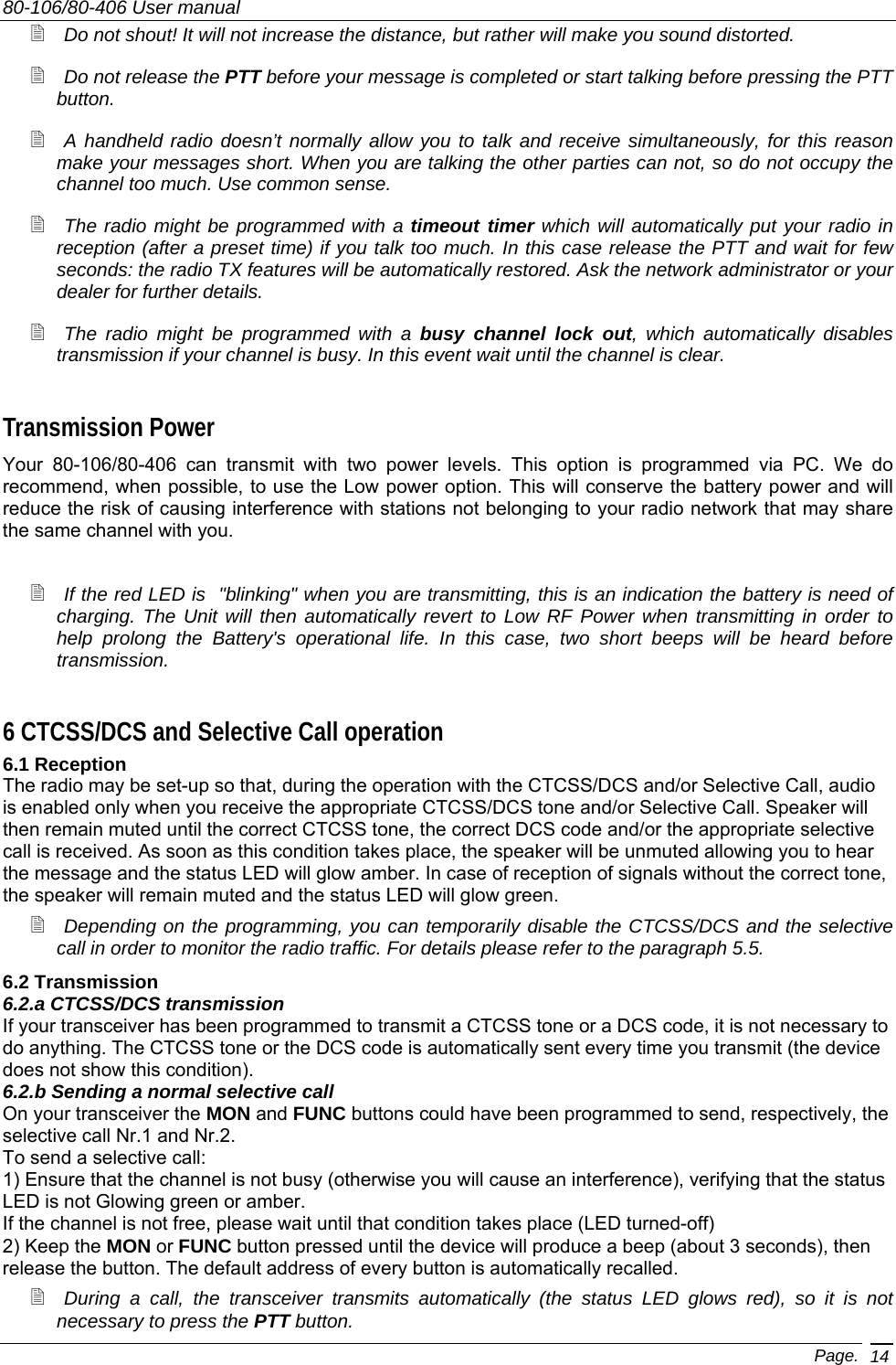
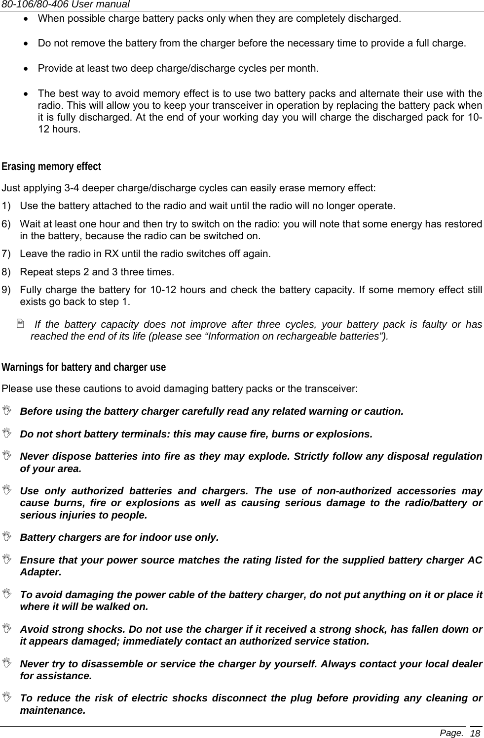
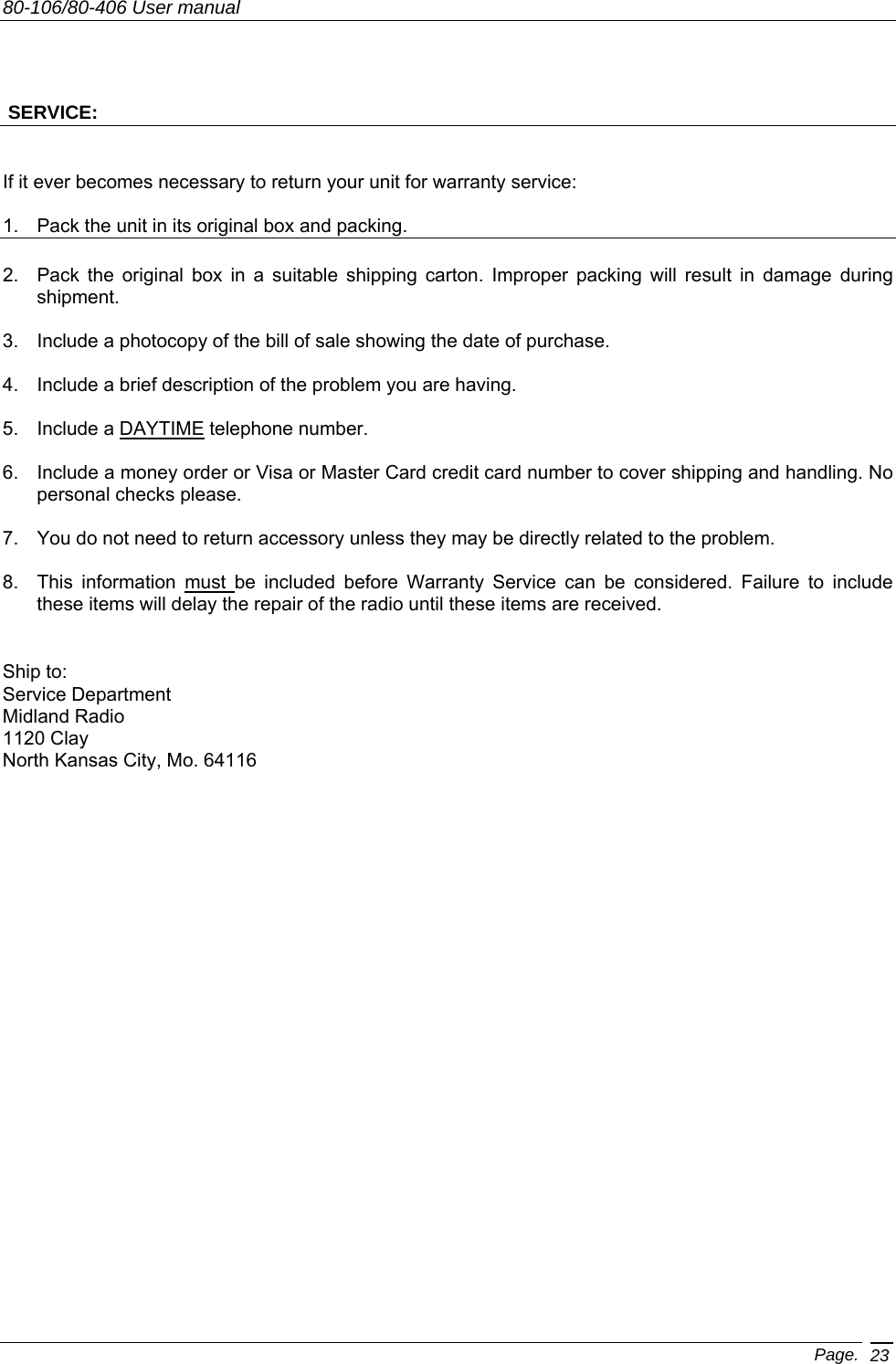
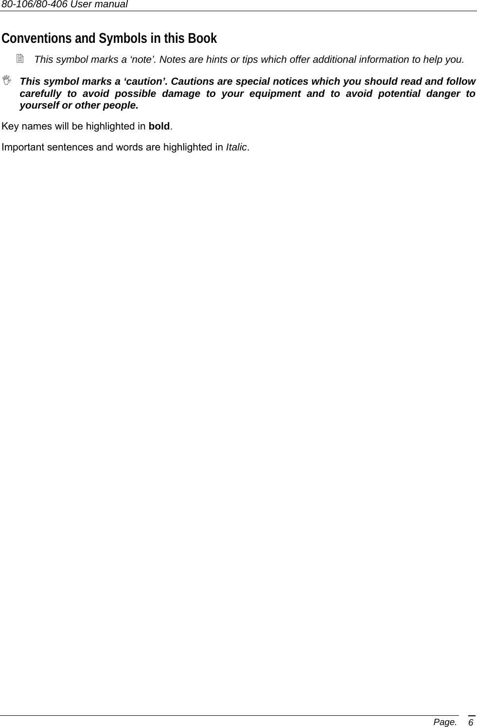
![80-106/80-406 User manual Page. 8 Side (left and right) [7] Microphone connector. For remote speaker/microphone, headsets for VOX use and other accessories. It must be protected with the supplied cap when not in use. For the related pin connections please see “Microphone Connection”. [8] Battery pack. This NiMH battery pack supplies energy to your radio. [9] Release button (located on the battery’s body). Allows you to remove the battery pack [10] MON (monitor) button. This button carries out different functions. The main ones are the following: • If you briefly press it, you will enable/disable the audio monitoring of the radio traffic on the selected channel (if enabled). For details please see the paragraph 5.5. • If you keep it pressed, the selective call #1 (if enabled) will be sent. For details please see the paragraph 6.2.b [11] PTT (Push To Talk) button. When pressed, it switches the transceiver from reception to transmission. For details please see the paragraph 5.6. [12] FUNC (Function) button. This button carries out different functions. The main ones are the following: • If you briefly press it, you can adjust the VOX sensitivity by switching one of two available levels. For details please see the paragraph 7.2.c • If you keep it pressed, the selective call #2 (if enabled) will be sent. For details please see the paragraph 6.2.b 10 11 12 789](https://usermanual.wiki/Midland-Radio/SP440/User-Guide-491232-Page-8.png)