Midland Radio T20 Two way radio User Manual T200 User interface definition V2 0
Midland Radio Corporation Two way radio T200 User interface definition V2 0
user manual
Midland Radio Corporation
T20 FRS portable transceiver
User interface Definition
Revision History
Version Description Date Author
1.0 Release 16FEB18 R Hollis
2.0 Added Weather mode activation; Changed product name from T200 to
T20. 19FEB18 R. Hollis
T20 User Interface Definition V2-0 Page 2 of 10
T20 User interface definition
The T20 portable transceiver user interface will consist of a 19mm x 13mm (active area) LCD display and
5 silicon rubber pushbuttons. The user will use the keypad and LCD to access all of the radio functions,
set or change operation parameters and to operate the radio.
Keypad
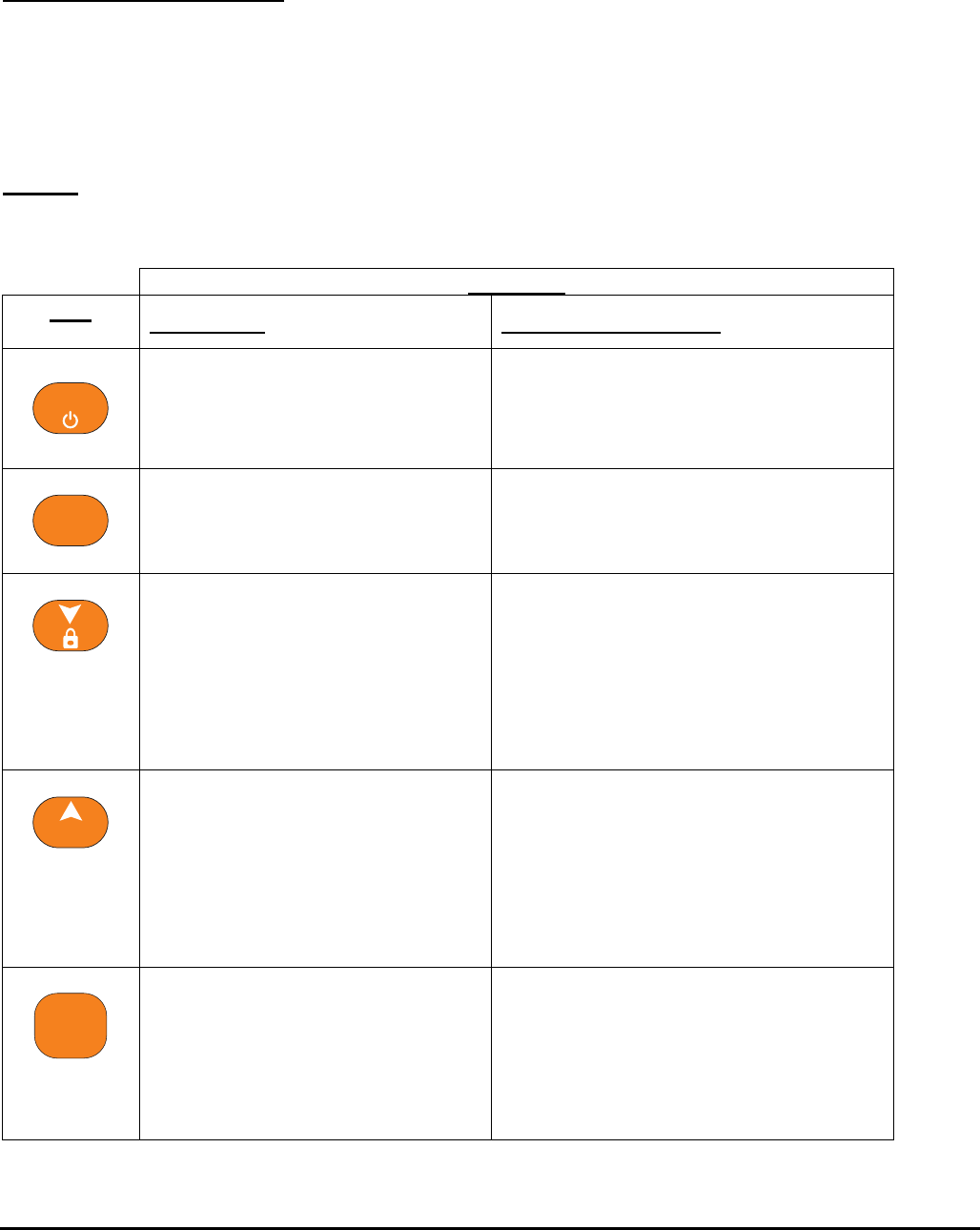
The keypad will consist of the following 5 keys:
Function
Key
Single press Long press (3 seconds)
Menu
Menu select Power
• Power on/off (toggle function – if
power is on, the unit will turn off.
If power is off, unit will turn on.)
MON
SCAN
SCAN
• Scan function on/off (toggle
function)
MON
• Monitor function on/off (toggle
function)
Down ARROW
• In standby, receive or
weather mode, this button
adjusts volume down.
• In menu mode (FRS and
weather), this button moves
the user down through
feature selections.
LOCK
• Locks and unlocks the keypad
functions. (toggle function)
CALL
Up arrow
• In standby, receive or
weather mode, this button
adjusts volume up.
• In menu mode (FRS and
weather), this button moves
the user up through feature
selections.
CALL
• Causes radio to transmit call tone
on selected channel.
PTT
Push to talk
• Press and hold the PTT
button to transmit.
• In menu mode a single
push of the PTT button will
save the current setting and
exit menu mode.
There is NO long press function for the
PTT button.
Midland Radio Corporation
T20 User Interface Definition V2-0 Page 3 of 10
Display
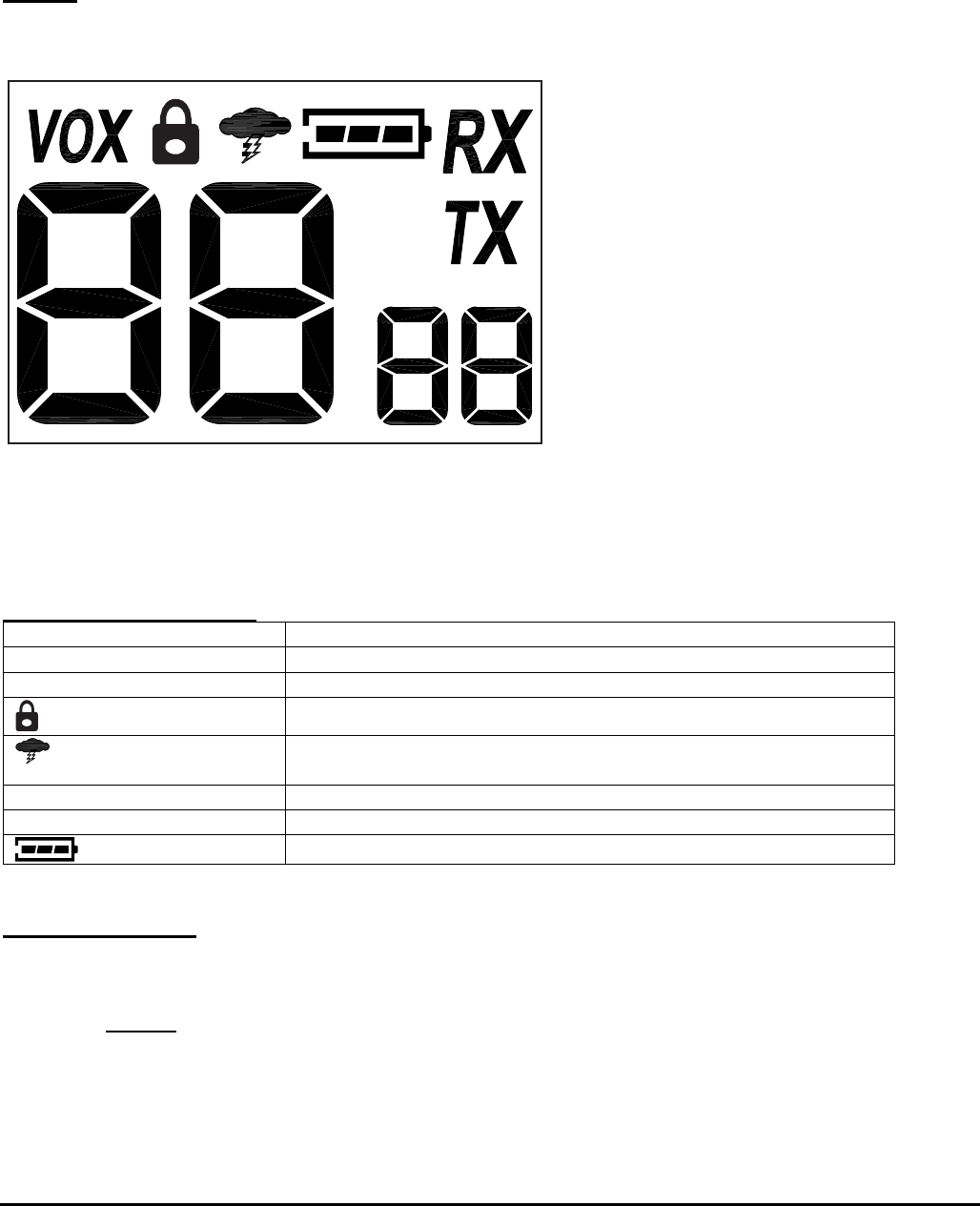
The radio will have an LCD for displaying user information as follows:
T20 LCD
LCD segment description
Large 7
-
segment
–
2 digits
Channel number
Small 7 segment
–
2 digits
CTCSS code
VOX Voice Activated microphone indicator
Indicates locked keypad. (PTT still active)
Indicates weather radio mode. Flashing if weather alert is
active.
RX Active when radio is receiving
TX
Active when radio is transmitting
Battery level indicator
Modes of operation
The radio has 5 modes of operation when the unit is powered on.
1. Standby
In Standby Mode, the radio is monitoring the current selected channel and will switch to Receive
mode if activity is detected.
Midland Radio Corporation
T20 User Interface Definition V2-0 Page 4 of 10
2. Receive
In receive mode, the radio has detected activity on the current selected channel and that activity
will be heard by the user on the speaker.
3. Transmit
In transmit mode, any audio picked up by the microphone will be broadcast on the current
selected channel. Transmit mode is entered one of 2 ways:
a. When the user presses the PTT button. The radio will stay in transmit mode as long as the PTT
button is depressed or until 180 seconds has elapsed. (Releasing the PTT will restart the 180
second timeout.)
b. If VOX is turned on, any audio detected by the microphone will be broadcast.
4. Scan
In scan mode, the radio will scan all channels (1 – 22) for activity.
5. Weather
In weather mode, the radio will monitor a user selected NOAA weather channel (1-10). If weather
alerts are turned on, the radio will periodically check for a weather alert tone (on the selected
channel) and automatically switch to Weather mode if an alert tone is detected.
BATTERY LEVEL INDICATION
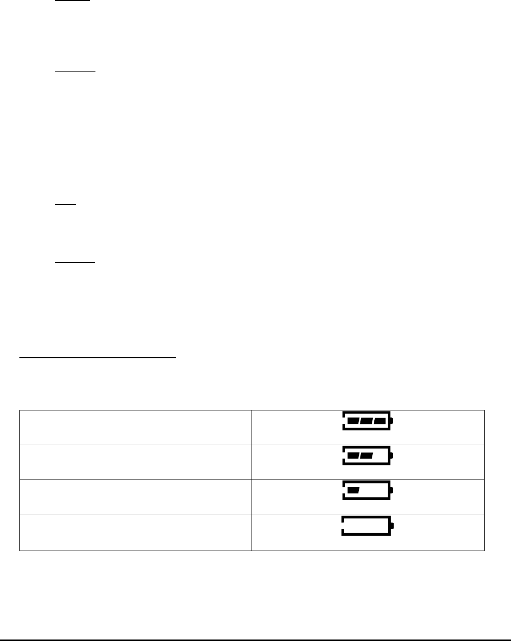
• The radio will have a BATTERY LEVEL METER that shows the battery power level. The greater the number
of bars visible, the stronger the battery level.
o 3 Bars = Full Battery
o 2 Bars = 2/3 Battery
o 1 Bar = 1/3 Battery
o No bar = battery low
(Flashing)
• The BATTERY LEVEL METER is visible at all times while the radio is powered on.
(Actual trigger voltages for these 4 levels will be defined in the T200 technical specification.)
Midland Radio Corporation
T20 User Interface Definition V2-0 Page 5 of 10
User operation:
POWER ON/OFF
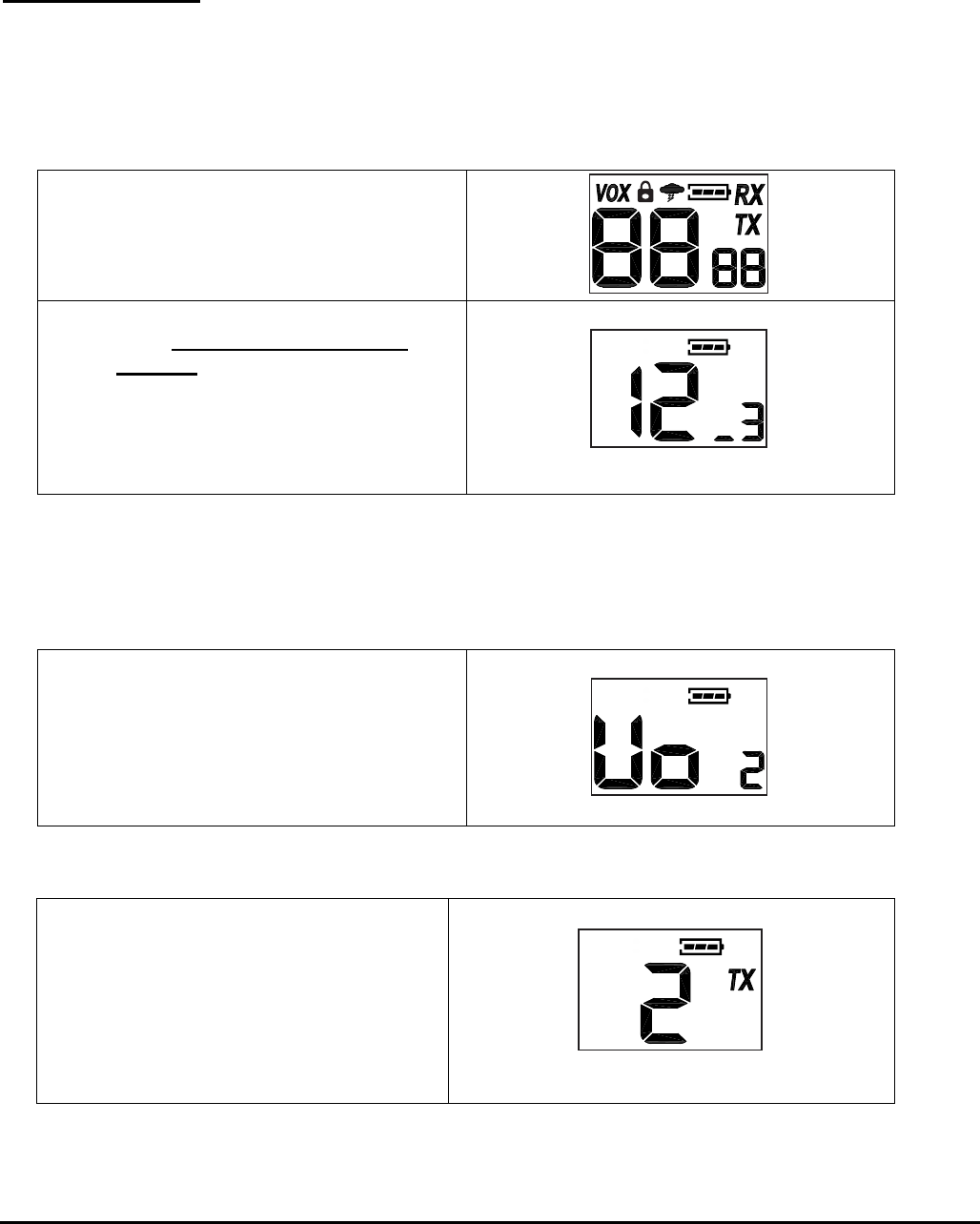
Press and hold the MENU/POWER button for 3 seconds to turn the radio on/off. During Power On,
the radio will beep once.
• The LCD will display all icons for 1
second and the LCD display will
indicate the last channel selected.
• After 1 second, the display will show
icons based on the last saved
settings.
(example shows channel 12 with
CTCSS of 3, no VOX, no weather
alert)
Note that a leading 0 is displayed as a single bar.
(segment “d”)
Volume up/down
To increase/decrease the volume level, press and release the ^/CALL or v/LOCK buttons during RX
or STANDBY mode
• The LCD will display Vo on the
channel digits and the volume level
on the CTCSS digits. The volume
level will increment or decrement as
the ^/CALL and v/LOCK keys are
pressed.
Transmitting and receiving
To TRANSMITT
• Press and hold the PTT button.
The TX icon will appear
continuously on the LCD display
while transmitting.
Transmitting, channel 2, no CTCSS.
Midland Radio Corporation
T20 User Interface Definition V2-0 Page 6 of 10
To RECEIVE
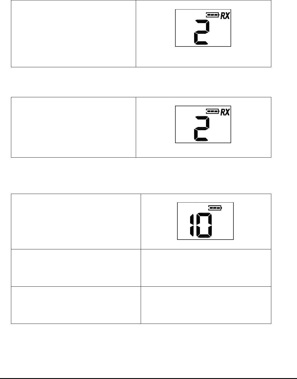
• The radio is ready to receive any
time the PTT button IS NOT
pressed. The RX icon will
appear on the display when the
radio is receiving a transmission.
The RX icon will go off when there
is no receive signal.
Recieving, channel 2, no CTCSS.
MONITOR
• Press and hold the MON/SCAN
button for 3 seconds to enter and
exit Monitor Mode
The RX icon will be shown constantly while in Monitor
mode even when there is no channel activity.
SCAN
• Press and release the MON/SCAN
button to enter and exit scan mode.
• The radio will scan each of the 22
channels at a 1/3 second rate and
stop on any active channel for 6
seconds before resuming scan.
• If the PTT button is pressed to
transmit on any channel, the
scanning function will stop and
remain on that channel.
Midland Radio Corporation
T20 User Interface Definition V2-0 Page 7 of 10
SCAN….continued
• If the ^/CALL or v/LOCK button is
pressed while the radio is scanning,
the scan direction will change to
increasing or decreasing
corresponding to which key is
pressed.
• If CTCSS is currently set for any
channel, that channel will be
scanned with the CTCSS code as
set.
• To resume scanning, press and
release the MON/SCAN button.
CALL
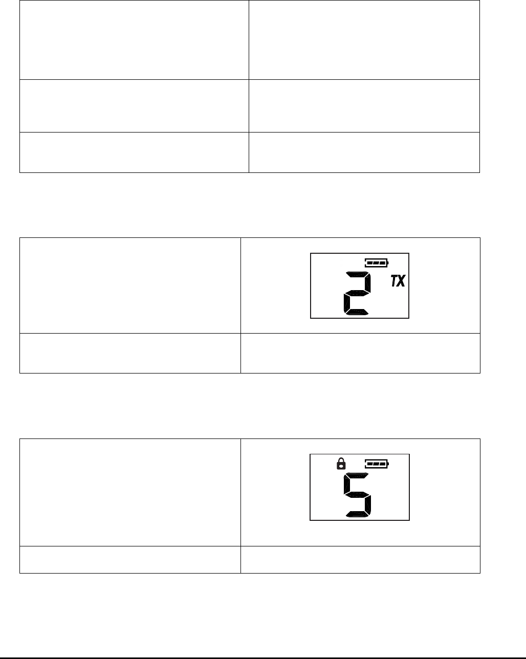
• To send a call alert, press and
hold the ^/CALL button for 3
seconds.
The TX icon will appear while transmitting a call alert.
• The call tone will be heard on the
speaker for confirmation.
KEYPAD LOCK
• To lock the keypad, press and
hold the v/LOCK button for 3
seconds.
• To unlock the keypad, press and
hold the v/LOCK button for 3
seconds.
The LOCK icon will appear on the display when the
keypad is locked.
• PTT and CALL buttons will still be
active.
Midland Radio Corporation

T20 User Interface Definition V2-0 Page 8 of 10
Weather mode
To enter Weather mode, press and hold both
the MON/SCAN and ^/CALL buttons at the
same time for 3 seconds. After 3 seconds,
the radio will enter Weather mode and monitor
the last channel set by the user.
RX is only active if the selected channel has an
audio signal present.
Press PTT to return to the FRS radio function.
Midland Radio Corporation
T20 User Interface Definition V2-0 Page 9 of 10
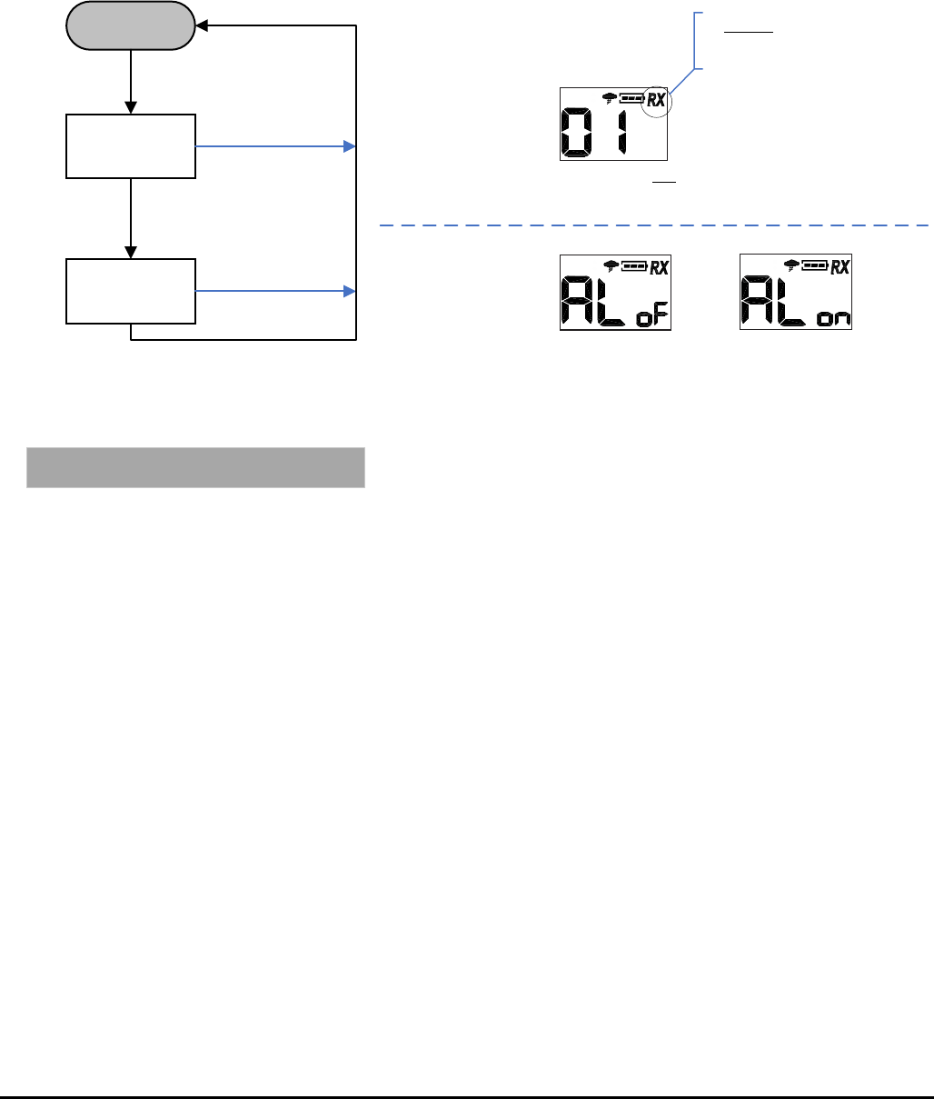
Feature select flowchart
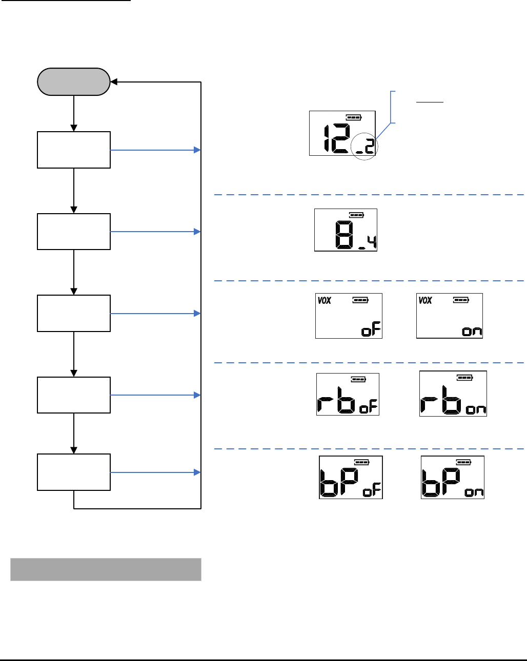
MENU key operation from
FRS Standby mode
Standby mode
Select channel
VOX On/Off
MENU press
Select CTCSS
MENU press
MENU press
Set Roger beep
MENU press
Set Silent mode
MENU press
MENU press
During feature selection, the MON/SCAN key is
inactive.
Channel number will flash and will
increment or decrement when ^/CALL
or v/LOCK are pressed.
CTCSS number will will flash and will
increment or decrement when ^/CALL
or v/LOCK are pressed.
CTCSS number will flash and increment
or decrement from oF to 38 when
^/CALL or v/LOCK are pressed.
Leading zeros will be shown as the
bottom segment of the digit.
Range of channels is 1 to 22.
VOX icon will be on. Smaller 7-segment digits will flash and
alternate between oF and on as ^/CALL or v/LOCK are pressed.
Large 7-segment display will show “rb”. Smaller 7-segment digits
will flash and alternate between oF and on as ^/CALL or v/LOCK
are pressed.
Large 7-segment display will show “bP”. Smaller 7-segment digits
will flash and alternate between oF and on as ^/CALL or v/LOCK
are pressed.
Midland Radio Corporation
T20 User Interface Definition V2-0 Page 10 of 10
MENU key operation
from Weather mode
Weather mode
Select channel
MENU press
Select Weather
alert ON/OFF
MENU press
MENU press
PTT press or
4 sec timeout will store
current setting
Channel number will flash and will
increment or decrement when ^/CALL
or v/LOCK are pressed.
Small 7-segment display will
alternate between oF and on when
^/CALL or v/LOCK are pressed.
Range of channels is 1 to 10.
Leading zero is displayed.
The weather icon wil flash in all
modes when weather alerts are
“on”.
Midland Radio Corporation
FCC Warning
Operation is subject to the following two conditions:
(1) This device may not cause interference, and
(2) This device must accept any interference, including interference that may cause undesired
operation of the device.
RF Exposure complianceStatement and operating instructions
The device has been tested against the SAR limit (1.6W/kg). The highest SAR value reported
under this standard during product certification for use at the Face up is 0. W/kg and when
properly worn on the body is 0.117W/kg. This device was tested for typical operations.
The device only supports simplex-mode and transmitting is no more than the rated duty cycle
factor of 50% of the time. For hand-held operation, the radio should be held at least 25mm from
the user's face. The use of belt clips, holsters and similar accessories should not contain
metallic components in its assembly. The use of accessories that do not satisfy these
requirements may not comply with RF exposure requirements, and should be avoided. Use only
the supplied or an approved antenna.
0
6
7
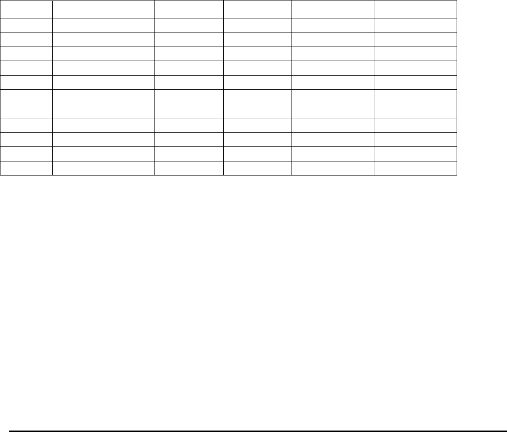
Channel List
Channel Frequency Model Channel Frequency Model
1 462.5625 FRS 12 467.6625 FRS
2 462.5875 FRS 13 467.6875 FRS
3 462.6125 FRS 14 467.7125 FRS
4 462.6375 FRS 15 462.5500 FRS
5 462.6625 FRS 16 462.5750 FRS
6 462.6875 FRS 17 462.6000 FRS
7 462.7125 FRS 18 462.6250 FRS
8 467.5625 FRS 19 462.6500 FRS
9 467.5875 FRS 20 462.6750 FRS
10 467.6125 FRS 21 462.7000 FRS
11 467.6375 FRS 22 462.7250 FRS
Midland Radio Corporation

ISEDC WARNING:
This device complies with Innovation, Science and Economic
Operation is subject to the following two conditions: (1) this
accept any interference,including interference that may cause
undesired operation of the device.
Le présent areil est conforme aux CNR d' l'innovation, la
areils radio exempts de licence.
L'exploitation est autorisée aux deux conditions suivantes:
(1) l'areil ne doit pas produire de brouillage, et
(2) l'utilisateur de l'appareil doit accepter tout brouillage
compromettre le fonctionnement.
Important
FCC& ISEDC RF Exposure Requirements: For body-worn operation, this radio
has been tested and meets the FCC ISEDC RF exposure guidelines when
used with Cobra accessories supplied or designated for this product. Use of other
accessories may not ensure compliance with FCC ISEDC RF exposure guidelines.
Use only the supplied antenna. Unauthorized antennas, modifications or
attachments could damage the transmitter and may violate FCC ISEDC regulations.
/
/
/
/
Tenir l'émetteur à environ 2.5 cm (1 po) de la bouche et parler normalement, l'antenne
Exigences de la FCC ISEDC concernant l’exposition aux champs électro-magnétiques RF
(radiofréquences): En ce qui concerne le fonctionnement de l’appareil porté sur le
corps de l’utilisateur, les tests effectués ont permis de vérier que cet
émetteur-récepteur satisfait aux directives FCC ISEDC limitant l’exposition aux champs
électro-magnétiques RF lorsqu’il est utilisé avec les accessoires Cobra fournis ou
conçus pour ce produit; l’utilisation d’autres accessoires peut ne pas garantir le
respect des critères des directives FCC ISEDC limitant l’exposition aux champs
électro-magnétiques RF. Utiliser l’appareil uniquement avec l’antenne fournie.
L’emploi d’une antenne non homologuée ou modiée, ou d’accessoires non autorisés,
pourrait faire subir des dommages à l’appareil, et peut violer les prescriptions de la
réglementation FCC ISEDC.
Position normale:
étant éloignée et dirigée vers le haut.
Hold the transmitter approximately 1 inches from your face and speak in a
normal voice, with the antenna pointed up and away.
/
/
/
/
science et le développement économique
Canada licables aux
Development Canada licence-exempt
RSS standard (s). device may not cause
interference, and (2) this device must
radioélectrique subi, même si le brouillage
est susceptible d'en
Channel List
Channel Frequency Model Channel Frequency Model
1 462.5625 FRS 12 467.6625 FRS
2 462.5875 FRS 13 467.6875 FRS
3 462.6125 FRS 14 467.7125 FRS
4 462.6375 FRS
5 462.6625 FRS
6 462.6875 FRS
7 462.7125 FRS
8 467.5625 FRS
9 467.5875 FRS
10 467.6125 FRS
11 467.6375 FRS
Midland Radio Corporation