Midmark RTLS Solutions VER1875 Asset Tag/Badge User Manual Direct
Versus Technology, Inc. Asset Tag/Badge Direct
Exhibit D Users manual per 2 1033 b3
Copyright 1991, 1992, 1993, 1996, 1998, and 2000 Versus Technology, Inc., all rights reserved.
This document contains user’s information on technology that is proprietary to Versus Technology, Inc.
Permitted transmittal, receipt, or possession of this document does not express license or imply any rights to use,
sell, design, or manufacture this information. No reproduction, publication or disclosure of this information, in
whole or in part, shall be made without prior written authorization from an officer of Versus Technology, Inc.
WARNING! This product is not designed, intended, authorized or warranted for use in any life support or
other application where product failure could cause or contribute to personal injury, death, or severe
property damage. This product or its systems are covered by one or more of the following U.S. Patents:
4,906,853; 5,017,794; 5,027,314; 5,119,104; 5,276,496; 5,355,222; 5,387,993; 5,548,637; 5,572,195,
6,104,295.
FCC STATEMENT: Components complying with part 15 of the FCC Rules – Operation is subject to the
following two conditions: 1) This device may not cause harmful interference, and 2) this device must
accept any interference received, including interference that may cause undesired operation.
Modifying or tampering with the transceiver’s or receiver’s internal components can cause a malfunction,
invalidate the warranty, and will void your FCC authorization to use these products.
Revision date: 1/29/2001

Contents
1. Introduction....................................................................................................................... 1
1.1 System Overview ...................................................................................................... 1
1.2 Terms and Definitions ............................................................................................... 1
1.3 Parts List................................................................................................................... 2
2. Eagle Eye Direct Hardware Components......................................................................... 3
2.1 Readers .................................................................................................................... 3
2.1.1 IR Reader....................................................................................................... 3
2.1.2 RF Reader...................................................................................................... 3
2.2 Tags ......................................................................................................................... 3
2.2.1 A Discussion about Active Tags...................................................................... 3
2.2.2 IR Tags........................................................................................................... 4
2.2.3 RF Tags ......................................................................................................... 4
2.2.4 IR/RF Tags..................................................................................................... 4
2.3 Perimeter Alarm Sentinel (PAS) ................................................................................ 5
2.4 Eagle Eye Direct Controller Board............................................................................. 6
3. Planning and Installation Guidelines ............................................................................... 7
3.1 Reader Location Planning ......................................................................................... 7
3.1.1 Reader Connection Length Limitations............................................................ 7
3.1.2 Cable Types ................................................................................................... 7
3.1.3 Infrared (IR) Reader Field-of-View................................................................... 7
3.1.4 Special Situations with IR Reader Locations ................................................... 7
3.1.5 RF Reader Location Planning ......................................................................... 8
3.2 Safety and Code Considerations ............................................................................... 8
3.2.1 Equipment Handling........................................................................................ 8
3.2.2 Codes and Ratings of Materials Used ............................................................. 9
3.2.3 Workmanship.................................................................................................. 9
4. Component Installation ...................................................................................................10
4.1 Cable Installation......................................................................................................10
4.2 Reader Installation ...................................................................................................10
4.3 Controller Board Configuration .................................................................................11
4.3.1 Terminal Strip Connections............................................................................12
4.3.2 Momentary Push-Button Switches..................................................................13
4.3.3 LED Indicators...............................................................................................14
4.3.4 DIP Switch Settings .......................................................................................15
4.4 Perimeter Alarm Sentinel Installation........................................................................17
4.4.1 Special considerations for installing the PAS unit ...........................................17
4.4.2 Range Adjustment .........................................................................................17

Eagle Eye Direct
1
1. INTRODUCTION
1.1 System Overview
Eagle Eye Direct is a system that allows you to use Versus Technology’s Active Radio Frequency
(RF) Identification tags and Versus Technology’s Infrared (IR) locator tags for real-time asset
identification, location, tracking and control. Removal of assets such as laptop computers can be
monitored as they leave a room or facility. The system transfers information using battery-powered
infrared (IR), radio frequency (RF) or a combination of IR and RF tags to transmit information to
infrared (IR) or radio frequency (RF) readers.
The Eagle Eye Direct Controller Board allows you to use Versus Technology’s tags directly with your
access control system through Wiegand reader ports on the access control panel. A tag ID is received
by the reader and sent to the controller board. The controller board converts this data to 2601
Wiegand data format and passes it to the access control panel.
Infrared (IR) Signals
The use of an IR signal has advantages for real-time tracking, since it allows accurate localization
using signals that will not penetrate walls or floors. An IR reader, strategically placed, receives IR
signals from active IR tags and provides location of assets or personnel.
Radio Frequency (RF) Signals
The use of an RF signal has advantages for asset tracking and control, since it allows assets to be
tracked even when placed inside a briefcase or other nonmetallic containers. RF signals can penetrate
walls and floors.
1.2 Terms and Definitions
The following terms will be used throughout this hardware installation guide, to refer to system
components and modes of operation.
Field-of-View – This term refers to the infrared detection pattern or area as seen by the “eyes” of the
readers.
IR Reader – An IR reader is a device that gathers infrared light energy and converts it to an electrical
signal, which is sent over a single pair of wires to an Eagle Eye Direct Controller Board.
Plenum – This term refers to any area that serves as a duct or passage for breathable air. Many office
buildings use the space above the suspended ceiling as a return air "plenum" for the heating and air
conditioning systems. Most laws require that any cables, which run in an air plenum, be made of
materials which will not burn, or which will not release toxic gases when burned. (Refer to local and
NFPA Safety and Fire Codes.)
RF Reader – An RF reader is a device that receives an RF signal and converts it to an electrical
signal, which is sent over a single pair of wires to an Eagle Eye Direct Controller Board.
Shielded Wire – This type of wire is wrapped in a braided or foil shield that protects it from electrical
interference. Versus Technology recommends the use of shielded wire. It may be the only solution in
a very high noise environment.

Versus Technology, Inc. 2
STP – Acronym for Shielded Twisted Pair - This is wiring usually used in data system installations
where electrical interference is a prime concern.
Termination – This term may refer to the mechanical method by which a wire is connected, or it may
refer to the electronic way that a wire is ended.
Twisted Pair –The wire used to connect readers is twisted into pairs to make the wire characteristics
uniform and to cancel out many types of interference to which the wires might be subjected.
UTP – Acronym for Unshielded Twisted Pair - This is the typical solid, paired wire used in phone
system installations. It has no outer shield layer.
Wiegand – This term refers to a data protocol that is used by most manufacturers of access control
panels.
1.3 Parts List
Part Number Description
VER-3500 Perimeter Alarm Sentinel
VER-3600 Eagle Eye Controller Board
VER-1875 Security Tag
VER-1700 Locator Badge
VER-1830 Asset Tag
3 Eagle Eye Direct
2. EAGLE EYE DIRECT HARDWARE COMPONENTS
This section contains a description of the hardware components that make up the Eagle Eye Direct
system.
2.1 Readers
Readers receive signals from tags and convert them into electrical signals. There are two reader types,
Infrared (IR) readers and Radio Frequency (RF) readers.
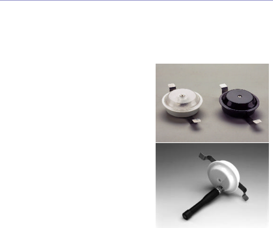
2.1.1 IR Reader
• Required for systems using Versus Technology
active infrared tags.
• Receives IR signals from IR and IR/RF tags.
• Converts IR signals into electrical signals.
• 360 degree horizontal coverage.
• 180 degree hemispherical vertical coverage.
2.1.2 RF Reader
• Required for systems using Versus Technology
active radio frequency tags.
• Operates at 433.9 MHz receive frequency.
• Receives RF signals from RF and IR/RF tags.
• Converts RF signals into electrical signals.
• 50 feet read range.
2.2 Tags
Tags are worn by personnel or attached to equipment. Tags send IR (infrared), RF (radio frequency),
or both IR and RF signals to the readers. This signal contains the “signature” that identifies the tag.
Motion, timing, battery state, and auxiliary information are all included in the signal.
Warning! A low battery can affect system performance. Change low batteries at first
indication.
2.2.1 A Discussion about Active Tags
Most Versus Technology tags are “active”, meaning they contain a battery and they transmit their
signature or ID number at regular intervals. For example, the Versus Infrared “Locator” tag transmits
its ID every 3.5 seconds when the tag is in motion. If the tagged item remains motionless for a period,
the tag will reduce its transmission rate to every 2.5 minutes. This is to conserve power consumption,
which extends the life of the battery, and to reduce unnecessary transmission signals.
4 Versus Technology, Inc.
2.2.2 IR Tags
IR tags send infrared signals from two emitters located at the top left and right corners of the tag case.
The signal is directed upward and somewhat forward at a wide angle to be received by the readers.
Better performance results by keeping the tag in an upright position.
Because IR tags use near-visible light to communicate with the readers, obstacles can hide the signal
from the readers. It is important to be aware that IR tags should not be covered or hidden from view.
This could result in a “missing” or “not-seen” tag and an event generated in the access control system.
IR tags have a unique feature that serves to extend battery life. They contain a motion-sensing circuit
that causes the tag to transmit most frequently when it is in motion and gradually reduces this
frequency when there is no motion. IR tags send a signal every 3.5 seconds when in motion, and
approximately every 2.5 minutes when not in motion.
Note: Static electricity can damage batteries. When changing tag batteries, it is critical to
be grounded using an anti-static strap and to replace the battery on an anti-static mat to
protect from any shock that would damage the battery or the tag.
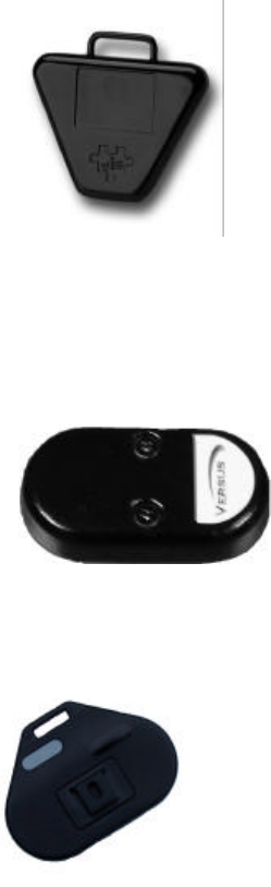
Infrared (IR) Locator Tag
• Ideal for locating people and portable equipment.
• Available with IR technology.
• Clips to clothing or can be suspended from a lanyard.
Optional mounting clip allows the tag to be attached to
portable equipment.
2.2.3 RF Tags
RF tags send radio frequency signals. Radio frequency signals can penetrate walls and ceilings. Some
Versus Technology RF tags send a signal every 2 minutes if not in alarm mode, regardless of the
motion of the tag. Tags with PAS technology installed will send a continuous signal if it is near a
Perimeter Activation System (PAS) unit.
Radio Frequency (RF) Security Tag
• Ideal for controlling removal of portable assets.
• Uses radio frequency (RF) technology.
• Transmits at 433.9 Mhz.
• Includes PAS technology for use with Eagle Eye Directs’
Perimeter Alarm Sentinel (PAS) unit.
• Mount using self-adhesive tape or #4 screws.
2.2.4 IR/RF Tags
The IR/RF (infrared/radio frequency) include both IR and RF technology. Some IR/RF tags feature a
communication/alert button.
IR/RF Personnel Tag
• Used for locating staff or visitors.
• Alert/call button feature.
• Includes both IR and RF technology.
• Clips to clothing or can be suspended from a lanyard.
Eagle Eye Direct
5
IR/RF Asset Tag
• Ideal for locating and controlling portable assets.
• Uses both IR and RF technology.
• Transmits at 433.9 Mhz RF.
• Includes motion circuit to conserve battery life.
• Mount using self-adhesive tape or #4 screws.
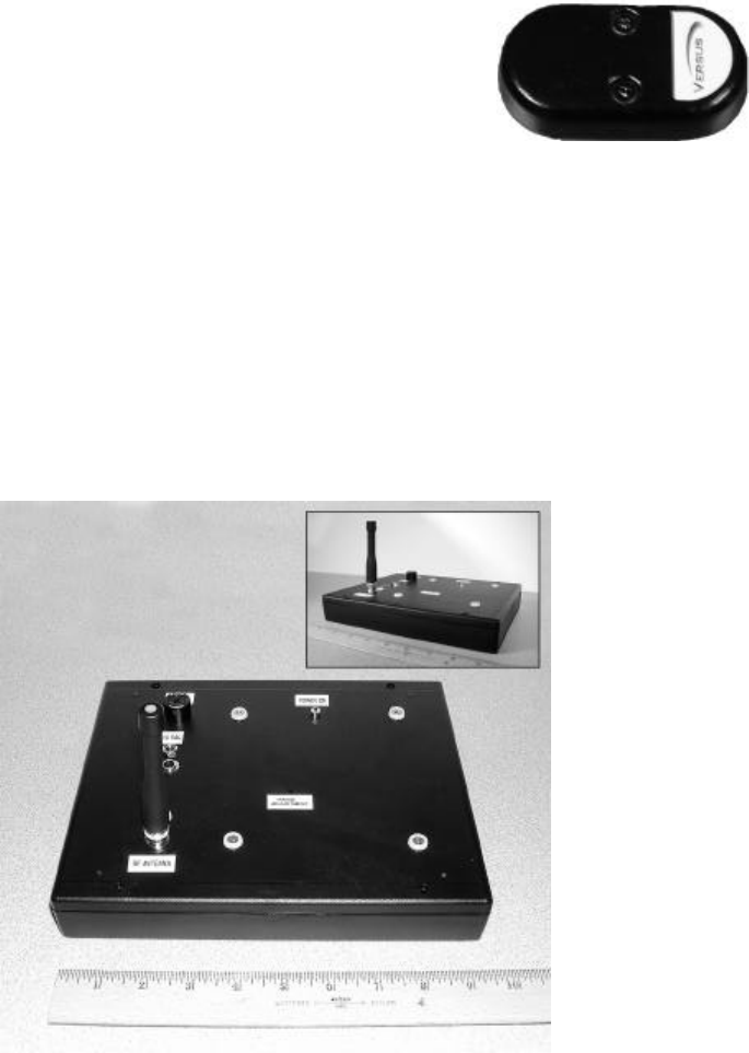
2.3 Perimeter Alarm Sentinel (PAS)
Perimeter Alarm Sentinel (PAS) is a unit that transmits a continuous 10.7 KHz signal. This signal
causes Versus Technology asset tags containing PAS technology to fire an RF signal. The signal is
received by a sensor inside the PAS unit and reported to the access control system. This assures that
assets that are tagged with RF tags are tracked at designated ingress and egress points within the
facility.
The PAS unit is a rectangular box with dimensions of 9.5”L x 1.3”H x 7.7”W. The unit plugs into a
110VAC electrical outlet with a 14VAC transformer. A transmitting coil inside sends the 10.7 KHz
signal. The signal of the strength can be adjusted from 0 to approximately 14 feet.
6 Eagle Eye Direct
2.4 Eagle Eye Direct Controller Board
The Eagle Eye Direct controller board allows you to connect Versus Infrared (IR) and/or Radio
Frequency (RF) readers directly to any existing access control panel that accepts 2601 Wiegand bit
structure format. This functionality allows any person or item entering a room or area to generate an
“In” or “Admitted” event in the existing access control system. This is the same as a person
presenting their proximity access card to a reader to gain access to the room. But, unlike the typical
access control system that generates no information when you pull your proximity card away from the
reader, the Eagle Eye Direct controller board also watches to see when a person or asset leaves the
detection field and generates an “Admin Out” or “Egress” event in the access control system.
The controller board serves two basic functions:
1. To convert VIS tag IDs to a Wiegand format.
2. To serve as a buffer for continuous transmissions from the tags and only pass data when:
a. The tag is first seen.
b. When the tag is no longer seen
c. Upon request
The “buffer” function is necessary so that all tagged assets or people are not sending a constant stream
of data to the access control system. There is a difference between a Versus Technology active tag and
a typical non-powered access card. The “passive” tag or card receives its power from the reader and
only sends data when excited by the reader. The Versus Technology “active” tag sends data at
constant intervals, from every .5 seconds to every 3 minutes. One hundred “active” tags in a room
could then be sending 100 “Admitted” events every second. The Eagle Eye Direct controller board
sends data only on the first “admitted” and buffers additional transmissions. Eagle Eye Direct is now
monitoring to see when a tag does not “report in” and at that moment, sends a 2601 Wiegand ID code
to the access control panel to say a tag has left the area.
All security protocol, annunciation such as bells, alarms, lights, camera call up, etc., is a function of
the existing access control system. If your system can create a “guard alert” when someone presents
their card to a door they are not authorized to access, your system can also generate that same alert
when a tagged asset is removed from a room without proper authority.

Eagle Eye Direct
7
3. PLANNING AND INSTALLATION GUIDELINES
When planning an installation, certain rules and limitations must be observed. The equipment has been
designed to provide trouble free operation in various environments, and adherence to the guidelines is
critical for a reliable installation. The following sections will detail what must be included in a system
plan to ensure a successful installation.
3.1 Reader Location Planning
Perhaps the most important step in an installation involves planning the reader locations. A complete
understanding of readers and tags is necessary to design an effective system. Experience will prove to
be invaluable in effective system design.
3.1.1 Reader Connection Length Limitations
The single pair reader connections may be up to 1000 feet in length. If the environment is known to
be electrically "noisy,” consider shorter line lengths to ensure strong signals and immunity to
interference.
3.1.2 Cable Types
For connecting readers to the Eagle Eye Direct controller board, Versus Technology recommends
stranded 22 AWG twisted pair cable.
3.1.3 Infrared (IR) Reader Field-of-View
An IR reader "sees" the environment under it in a largely predictable pattern. However, other factors
can affect the way a reader sees. The reader is like an eye, which is sensitive only to a narrow
spectrum of light, and the tag appears as a bright splash in an otherwise dark world to the reader. Even
if a tag is blocked from the view of a reader, it can often be detected. However, the infrared light from
a tag does not penetrate solid objects or bend around corners, it does reflect from surfaces in the room.
This can sometimes be mistaken for “seeing around corners.” The effect of reflection can be an
advantage if done correctly. The area that a reader can see is the readers “field-of-view.” Readers have
a given field-of-view when obstacles are not present, so the field-of-view of an installed reader may
vary depending on the room configuration.
Mounting a reader on a ceiling with a 10-foot height and without obstacles or reflections, the field of
view of the reader appears in the shape of six overlapping lobes forming a 16-foot radius. Lower
ceilings reduce the effective reader pattern diameter considerably due to angles involved. Mounting
above 10 feet will cause “spotty” detection and should be avoided.
3.1.4 Special Situations with IR Reader Locations
There are some things to remember when planning a reader installation.
Controlling the readers field of view
A reader may have a field-of-view that extends out of the designated area through a window, doorway
or passage. This can cause tags to be detected incorrectly and reported to be in the room when only
passing by. Place readers away from doors or entryways to prevent false tag detection. The position
of a reader can limit its field-of-view when placed in a location where existing obstacles will block the
unwanted reader field-of-view.
8 Versus Technology, Inc.
Due to the line-of-sight nature of the infrared light created by tags, it is also possible to apply masking
to the reader to limit or control the field of view. However, proper placement is always the preferred
method for controlling reader field of view.
Sunlight interference
If the room has windows that allow a large amount of sunlight to enter the room, place the reader in a
position where the sunlight does not reflect directly into it. Sunlight can decrease reader range and
field of view if allowed to enter the reader. Window tint films that block infrared (heat) energy greatly
reduce this effect.
The reader should be located so that it has the best possible view of the room. If the room has a
complex shape and no single reader position will provide adequate coverage, multiple readers should
be considered.
3.1.5 RF Reader Location Planning
Walls or other obstacles do not obstruct an RF reader receiving RF tag signals. RF signals are able to
penetrate briefcases, backpack, walls and ceilings. For this reason, RF readers are ideal for detecting
assets as they are removed from a facility. An RF readers range is approximately 50 feet in radius
with no interference. Because of different building configurations, the read range of an installed RF
reader will vary.
3.2 Safety and Code Considerations
Safety procedures and adherence to local building codes are the responsibility of the system installer.
Versus products have been designed to be safe and reliable under the use and conditions in which they
are intended. The following sections detail those aspects of the system that might affect safety.
3.2.1 Equipment Handling
The components used in a typical installation contain internal circuits that are sensitive to static
electricity. Static electricity transported by the human body may be strong enough to damage internal
circuitry during installation. Most components do not normally have exposed connector pins, but if
handling with exposed connectors or pins is required, the installer should use an anti-static wristband
connected to an electrical ground. This is especially important when temporarily disconnecting and
reconnecting cables.
WARNING!
Avoid touching bare contacts or connector pins when handling system
components in order to prevent the accidental transfer of static to
internal devices. Leave protective covers attached during installation.
The hardware may be damaged if connections are made with the system
power applied. Do not attempt to connect or disconnect readers with
power applied! Doing so may void equipment warranties.
Allowing cables to come into contact with metal surfaces and structures,
or allowing wires to be routed in close proximity of high powered
equipment or devices can introduce electrical interference and may
cause erratic operation and/or equipment failure.
Eagle Eye Direct
9
3.2.2 Codes and Ratings of Materials Used
The materials used in the construction of individual components meet or exceed UL fire retarding
requirements. However, not all these devices are rated for air plenum use. They are intended for utility
closet mounting and must not be placed in airways or plenum areas, unless they can be housed in
approved enclosures and sealed to meet local codes.
Installers must be aware of local fire and health codes in their selection of interconnect wiring.
Plenum-rated wire and cable must be used where it will pass through breathable air spaces. Wire and
cable rated for plenum must be clearly marked.
3.2.3 Workmanship
The following standards of workmanship must be followed during installation:
• National and local building codes must be followed.
• Connections must be made with manufacturer’s recommended tools and procedures.
• Conductors must not be nicked nor wire strands cut during wire stripping.
• Wire bundles must be neatly dressed.
• Wire bundles must be spaced away from power cables and lighting.

10 Eagle Eye Direct
4. COMPONENT INSTALLATION
This section covers the installation of the Eagle Eye Direct system components. Before installing the
components, all planning should be completed as described in section 3.
4.1 Cable Installation
When installing reader wiring, use industry standard installation techniques. Reader wire runs
should allow sufficient length to move ceiling tiles and perhaps to move readers if needed.
4.2 Reader Installation
Important: When installing the readers, be sure to label both ends of the wire. Keep a list that includes
the labeled number and the location, area, exit or room where the reader is installed.
The single pair reader connections may be up to 1000 feet in length. For connecting readers to the
Eagle Eye Direct controller board, Versus Technology recommends stranded 22 AWG twisted pair
cable.
Handle the readers with care so as not to scratch or damage the casing.
WARNING!
Always disconnect power from the system before connecting or
disconnecting components. Failure to do so may damage the equipment.
Only a single pair of 22 AWG shielded wire is required for each reader. No grounding at the reader is
required. Reader installation calls for use of a splice connector at the reader end of the cable run.
Reader wires are red and black.
To install and wire readers (in ceiling tiles):
1. Create holes for readers in ceiling tiles or ceiling surfaces using a 2-3/8" hole saw.
2. Connect the reader cable wire-pair to each reader (Versus recommends using UY splice
connectors).
3. Place the reader into the hole and secure using the spring steel clip and the reader cover to
“sandwich” the ceiling tile. The spring steel clip securely holds the reader against the ceiling
tile allowing for easy access for installing or replacing readers.
4. On the Controller Board, connect the red wire (positive) to terminal 13 and the black wire
(negative) to terminal 14 for a “enter” reader. For an “exit” reader, connect the red wire
(positive) to terminal 15 and the black wire (negative) to terminal 16.
Eagle Eye Direct
11
4.3 Controller Board Configuration
WARNING!
Never connect or disconnect components, cables or wires without
removing power first!
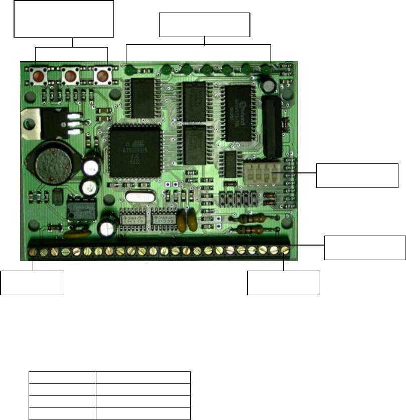
Controller Board
Mount the controller board using normal mounting procedures using the mounting brackets supplied
with the unit.
The maximum distance of the controller board from the control panel is as follows:
Wire Gauge Maximum distance
22 200 feet
20 300 feet
18 500 feet
Terminal Strip
DIP Switches
LED Indicators
Terminal 1 Terminal 24
Momentary Push
Buttons

12 Versus Technology, Inc.
4.3.1 Terminal Strip Connections
The 24-point terminal strip provides for all connections and terminations using 22 AWG wire or
cable. With the controller board facing you and the terminal strip at the bottom of the board, terminal
1 is the left-most terminal.
• Power – Terminals 1 and 2
Warning! Always power down before making any connections to the controller board.
Terminal 1 and 2 are power for the controller board. Power is 24 VAC. Terminal 1 is positive and
terminal 2 is negative. Maximum current draw is 180ma.
1) Power (Positive)
2) Power (Negative)
• Output Alert – Terminals 3 and 4
Terminals 3 and 4 provide a Normally Open SPST output relay (rated .5 amp). Terminals 3 and 4
provide a .75 second closure anytime a tag transmits a low battery, buffer full, tamper or button push
signal.
3) Output (Normally Open)
4) Output (Common)
• Reset Controller Input – Terminals 5 and 6
A .5 second closure across terminals 5 and 6 provides a “reset” of the processor. All “seen” tag IDs
will be first sent to Wiegand Port 2. The controller board will reboot and all “seen” tags will again be
reported to Wiegand Port 1.
5) Reset
6) Reset (Return)
• Query and Report All “Seen” Tags – Terminals 7-10
A .5 second closure across terminals 7 and 8 will cause the controller board to send the ID or code of
all tagged items or “seen” tags to Wiegand Port 1. This feature is used to Query a room or location to
generate an immediate report to the access control system of all items it that room.
7) Query 1
8) Query 1 (Return)
A .5 second closure across terminals 9 and 10 will cause the controller board to send the ID or code of
all tagged items or “seen” tags to Wiegand Port 2. This feature is used to Query a room or location to
generate an immediate report to the access control system of all items it that room.
9) Query 2
10) Query 2 (Return)
Note: Terminals 11 and 12 are Not Used (Reserved).
Terminal 1
Eagle Eye Direct
13
• Versus Reader Connections – Terminals 13 and 14
Versus tags emit either an Infrared ID or a Radio Frequency ID. Either a Versus Infrared reader or a
Radio Frequency reader receives this signal. Versus readers require only two wires/cables for both
power and signal. This 22 AWG twisted pair shielded cable can be up to 1,000 feet in length.
Connect the red or positive wire to terminal 13 and the black or negative wire to terminal 14.
13) IR/RF Room (Positive)
14) IR/RF Room (Negative)
• Exit Reader/Detector – Terminals 15 and 16
An exit reader is used when it is necessary to cancel the “wait” or “missing” tag signal. As previously
explained, a Versus IR Locator tag transmits every 3.5 seconds when in motion but only every 2.5
minutes when not in motion. This requires the controller board be set to expect a signal every 5
minutes minimum. At the end or expiration of that 5 minute-wait period, the tag ID will be sent to
Wiegand Port 2 if the tag is missing or not seen. By connecting a second Versus IR reader to
terminals 15 and 16 and placing this reader outside the “protected” room, any tag seen by this reader
will cancel the “wait” time and immediately send this tag ID to Wiegand Port 2.
15) IR/RF Exit (Positive)
16) IR/RF Exit (Negative)
• Wiegand Port One (Asset In) – Terminals 17-19
Terminals 17, 18 and 19 provide the connection to the access control panel reader ports. Terminal 17
is data zero (green), terminal 18 is data one (white) and terminal 19 is ground (black).
17) Wiegand Port 1 - DATA 0
18) Wiegand Port 1 - DATA 1
19) Wiegand Port 1 - Ground
• Wiegand Port Two (Asset Out) – Terminals 20-22
Terminals 20, 21 and 22 provide the connection to the access control panel reader ports. Terminal 20
is data zero (green), terminal 21 is data one (white) and terminal 22 is ground (black).
20) Wiegand Port 2 - DATA 0
21) Wiegand Port 2 - DATA 1
22) Wiegand Port 2 - Ground
Note: Terminals 23 and 24 are Not Used (Reserved).
4.3.2 Momentary Push-Button Switches

14 Versus Technology, Inc.
With the controller board facing you and the LED Indicators and the red Switches at the top, the left
most switch is switch 1.
The three red “push buttons” duplicate the functions of terminals 5 through 10.
• SW1 – Push button one will reset the controller board.
• SW2 – Push button two will cause all “seen” tags to report to Wiegand Port 1.
• SW3 – Push button three will cause all “seen” tags to report to Wiegand Port 2.
4.3.3 LED Indicators
Viewing the LED’s from left to right:
• LED 1 – indicates power is applied to the controller board.
• LED 2 – will flash for .25 seconds, anytime a tag transmits its ID and is received by the Versus
room reader.
• LED 3 – will flash for .25 seconds, anytime a Wiegand ID code is transmitted to Wiegand Port 1.
• LED 4 – will flash for .25 seconds, anytime a tag transmits its ID and is received by the Versus
exit reader.
• LED 5 – will flash for .25 seconds, anytime a Wiegand ID code is transmitted to Wiegand port 2.
• LED 6 – will flash for .5 seconds, anytime a tag transmits a Low Battery or Tamper signal.
• LED 7 – is a multifunction LED. It will flash once every 2 seconds just to show that the
controller board is operational. It will light continuously, anytime the controller board is
“watching” as many tags at one time as the unit can handle. The controller board can “store” a
maximum of 200 ID codes. If the buffer is full, the “supervision” relay (terminals 3 and 4) will
close for .75 seconds.
LED 1
LED 7
SW1
SW2
SW3
Eagle Eye Direct
15
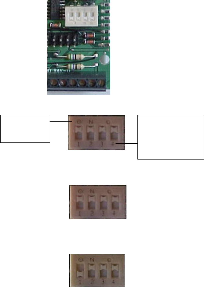
4.3.4 DIP Switch Settings
A four-position DIP switch allows for application specific settings of the controller board. When a tag
is first seen by a sensor, the controller board sends this information to the access control system. To
determine when a tag has exited the area, there are two situations that will cause the controller board
to report this to the access control system. First, if there is an “exit” reader, when the tag is seen by the
exit reader, the controller board will report this to the access control system. Secondly, once a tag is
reported as seen, the controller board will wait a specified period of time in which the tag is not seen,
and after this period of time, will send the “exit” information to the access control system. The DIP
switch settings determine how long the controller board will wait before it reports an unseen tag as
having exited.
The switches are labeled 1-4, with the on position labeled as “ON”.
With ALL switches in the ON position, any “tag-not-seen” within 5 seconds will cause its ID to be
sent to Wiegand Port 2.
Moving switch 1 to the OFF position, a “tag-not-seen” within 15 seconds will be transmitted to
Wiegand Port 2.
The on
position is
labeled “ON”.
The switches are
labeled 1-4. The
numbers are on the
OFF position of the
switch.
All switches in
the ON
position.
Switch 1 OFF,
switches 2-4 ON.

16 Versus Technology, Inc.
Leaving switch 1 in the ON position and moving switch 2 to the OFF position will cause a “tag-not-
seen” within 30 seconds to transmit the code to Wiegand Port 2.
Moving both switch 1 and 2 to the OFF position will cause the “tag-not-seen” ID within 60 seconds,
to be transmitted to Wiegand Port 2.
Measuring time in minutes instead of seconds
Moving switch 3 to the OFF position will change the “tag-not-seen” report to wait for minutes instead
of seconds, example 5, 15, 30 or 60 Minutes.
DIP Switch 4 is not used and must be left in the ON position.
Switch 2 OFF,
switches 1, 3, and 4
ON.
Switches 1 and 2
OFF, switches 3
and 4 ON.
Switch 3 OFF
changes the wait
time from seconds to
minutes.
In this example, the wait time will
be 5 minutes until the “tag not
seen” signal is sent to Wiegand
port 2.
In this example, the wait time will
be 15 minutes until the “tag not
seen” signal is sent to Wiegand
port 2.
Eagle Eye Direct
17
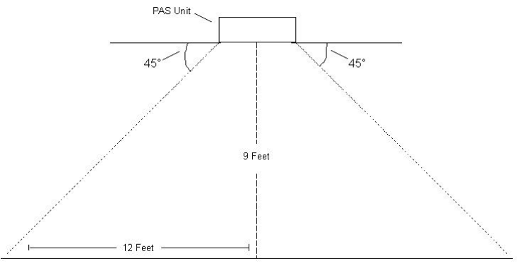
4.4 Perimeter Alarm Sentinel Installation
The Perimeter Alarm Sentinel (PAS) unit has a 14VAC transformer with a 6’ cable. It needs to be
plugged into a 110VAC outlet. The PAS unit is placed near the ceiling in the proximity of doorways
where assets and people need to be tracked as they enter and exit. The exact location of the PAS unit
will depend on the read range needed, but it is recommended that the unit be slightly out from the
doorway and not mounted directly above the doorway. The PAS unit causes RF tags with PAS
technology to send a signal when in proximity to the PAS unit. The unit should be mounted at a
minimum height of 8 feet, and a maximum of 10 feet. The signal goes out from the unit at
approximately a 45-degree angle.
Approximate range of signal with PAS unit mounted at a height of 9 feet:
There are several options for mounting the PAS unit. Mounting the unit out of view, such as above
ceiling tile, will decrease the likelihood of tampering with the unit.
1. You can set the PAS unit on a shelf above the doorway. The shelf must be non-metallic.
2. You can place the PAS unit above the ceiling tile if there is a suspended ceiling. If you choose
this method, do not place the unit on the metal frame of the ceiling, but rather touching only the
ceiling tile.
4.4.1 Special considerations for installing the PAS unit
• Do not hang or place the unit on a metal wall or near metal surfaces or metal objects such as
appliances, as metal objects can alter the magnetic field and change the transmitting range.
• Do not place the unit near audio speakers.
4.4.2 Range Adjustment
The signal of the strength can be adjusted from 0 to approximately 14 feet.