Midmark RTLS Solutions VER4054 Remote Station with 1/4" Jack User Manual Hardware Manual
Versus Technology, Inc. Remote Station with 1/4" Jack Hardware Manual
Exhibit D Users Manual per 2 1033 b3

Versus Information System
Hardware and Wiring
Installation Guide
VERSUS TECHNOLOGY, INC.
2600 MILLER CREEK ROAD
TRAVERSE CITY, MI 49684
(231) 946-5868
www.versustech.com
Versus Technology, Inc.
Hardware and Wiring Installation Guide i
Copyright 1991 – 2003 Versus Technology, Inc., all rights reserved.
This document contains user’s information on technology that is proprietary to Versus Technology, Inc.
Permitted transmittal, receipt, or possession of this document does not express license or imply any
rights to use, sell, design, or manufacture this information. No reproduction, publication or disclosure of
this information, in whole or in part, shall be made without prior written authorization from an officer of
Versus Technology, Inc.
WARNING! This product is not designed, intended, authorized or warranted for use in any life
support or other application where product failure could cause or contribute to personal injury,
death, or severe property damage. This product or its systems are covered by one or more of the
following U.S. Patents: 4,906,853; 5,017,794; 5,027,314; 5,119,104; 5,276,496; 5,355,222;
5,387,993; 5,548,637; 5,572,195; 6,104,295; 6,154,139.
FCC STATEMENT: Components complying with part 15 of the FCC Rules. Operation is subject to
the following two conditions: 1) This device may not cause harmful interference, and 2) this device must
accept any interference received, including interference that may cause undesired operation.
Modifying or tampering with the transceiver’s or receiver’s internal components can cause a
malfunction, invalidate the warranty, and will void your FCC authorization to use these products.
Revision date: 9/2003
Versus Technology, Inc.
Hardware and Wiring Installation Guide iii
Contents
1. Introduction...........................................................................................................................1
1.1 Purpose of This Guide ..................................................................................................1
1.2 Computer Requirements...............................................................................................1
1.2.1 Server Computer Requirements ......................................................................1
1.2.2 Computer Workstation Requirements Including Relay Controlled Devices.....1
1.3 Terms and Definitions ...................................................................................................2
1.4 Versus Hardware Parts List ..........................................................................................3
1.5 Versus Information Systems Estimated Bandwidth Requirements ..............................3
2. System Description ..............................................................................................................4
2.1 Infrared (IR) Tracking ....................................................................................................4
2.2 Radio Frequency (RF) Signals......................................................................................4
2.3 System Hardware Components ....................................................................................5
2.3.1 Badges .............................................................................................................5
2.3.2 Sensors ............................................................................................................6
2.3.3 Collector (VER-2402) .......................................................................................7
2.3.4 Ethernet Concentrator (VER-2015)..................................................................8
2.3.5 Other Optional Hardware .................................................................................8
3. Planning the Installation ....................................................................................................10
3.1 General Steps for Installing a Versus System ............................................................11
3.2 Collector and Concentrator Location Planning ...........................................................13
3.2.1 Collector Network Length Limitations ............................................................13
3.3 Sensor Location Planning ...........................................................................................13
3.3.1 Sensor Connection Length Limitations ..........................................................14
3.3.2 Infrared (IR) Sensor Location Planning .........................................................14
3.3.3 RF Sensor Location Planning ........................................................................17
3.3.4 Mapping the Sensor Locations on the Floorplan ...........................................18
3.3.5 Mapping the Relay Device Locations ............................................................19
3.4 Use of Unauthorized Components..............................................................................20
3.5 List of Recommended Tools .......................................................................................20
3.6 Safety and Code Considerations ................................................................................21
3.6.1 Equipment Handling.......................................................................................21
3.6.2 Power Requirements .....................................................................................21
3.6.3 Grounding of Equipment ................................................................................22
3.6.4 Codes and Ratings of Materials Used ...........................................................22
3.6.5 Workmanship .................................................................................................22
4. System Hardware Installation ...........................................................................................23
4.1 Cable Installation.........................................................................................................23
4.1.1 Cable Types ...................................................................................................23
4.2 Sensor Installation.......................................................................................................23
4.3 Collector and Concentrator Installation.......................................................................24
4.4 Connecting Sensors to Collectors...............................................................................25
4.5 Communication Room Check .....................................................................................27
4.5.1 Checking the Collector Wiring........................................................................27
4.5.2 Terminating the Last Collector .......................................................................28
4.5.3 Testing Sensor Voltage..................................................................................28
4.5.4 Connecting Collectors and Concentrators .....................................................29
4.5.5 Network Wiring for Ethernet Concentrators ...................................................31
4.5.6 Concentrator Power-up Test..........................................................................31
4.6 Walking Setup Test.....................................................................................................32
4.7 Testing RF Sensors ....................................................................................................32
4.8 Relay Board Installation ..............................................................................................33
4.8.1 Power Requirements .....................................................................................35
4.8.2 Wire Size Determination ................................................................................35
4.9 Corridor Light Installation ............................................................................................36
4.10 Badge/Tag Wearing and Mounting .............................................................................36
4.10.1 Proper Wearing of the Versus Personnel Alert Badge ..................................37
4.10.2 Proper Mounting of the Versus Asset Tag.....................................................37
4.10.3 Proper Mounting of the Versus Remote Station ............................................39
5. Troubleshooting Guide ......................................................................................................40
5.1 Badge Battery Replacement .......................................................................................41
5.1.1 Locator Badge (VER-1700)............................................................................41
5.1.2 Personnel Alert Badge (VER-1780) ...............................................................41
5.1.3 Asset Tag (VER-1830)...................................................................................42
5.2 Collector Voltage Troubleshooting Flowchart .............................................................43
5.3 Functionality Test Flow Chart .....................................................................................44
6. Installation Forms...............................................................................................................45
6.1 Computer Setup ..........................................................................................................47
6.2 Installation Plan...........................................................................................................49
6.3 Final Verification..........................................................................................................55
6.4 Installation Checklist ...................................................................................................57
6.5 Punch-down Block Wire Organization List..................................................................59
6.6 Communication Room Checklist.................................................................................61
6.7 Preventative Maintenance Inspection Report .............................................................63
6.8 Relay Board Organization List ....................................................................................67
Versus Technology, Inc.
Hardware and Wiring Installation Guide 1
1. Introduction
1.1 Purpose of This Guide
This document is intended to provide the information required to install the hardware and wiring
components of a VIS system. Read this entire document before proceeding with the installation. A
general understanding of wiring and telephone installation techniques is assumed.
1.2 Computer Requirements
The VIS software runs in the Microsoft Windows 2000, NT or XP environments and requires a
computer system with reasonable capacity and speed.
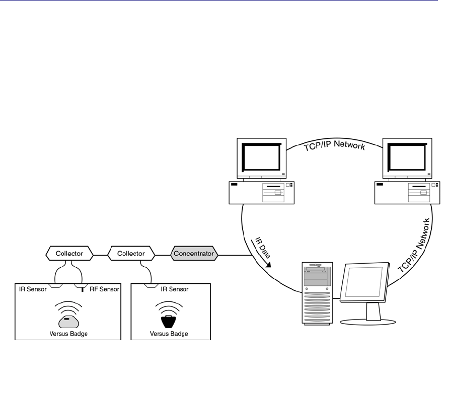
1.2.1 Server Computer Requirements
The minimum computer requirement for the server computer running the Data Server, Badge
Server and Configuration Utilities are:
Operating System Windows 2000 or XP, Pro or Server version recommended
Processor Current shipping model or better
Memory 256 MB RAM or more, depending on operating system
Hard drive 40 GB or equivalent
2nd Hard Drive 40 GB hard drive for purpose of redundancy
Floppy Disk Drive 3.5 1.44 MB
CD-ROM 48X CD-ROM or better, CD-RW optional
Sound Card Standard sound card or better (optional)
Speakers Standard Speakers (optional)
Network Card Standard Ethernet Card
Modem 56K Data/Fax Modem (optional)
Tape Backup 10/20GB, SCSI, Travan-5 or Equivalent (recommended)
UPS UPS recommended
These are minimums only; additional resources may be needed depending on the size of the
system.
1.2.2 Computer Workstation Requirements Including Relay Controlled Devices
As part of the Versus System, relay controlled devices (such as corridor lights) can be connected
to relay boards, which are then connected to a computer that contains a relay control board. The
computer that contains the relay control board will also have the Relay Control software installed
for configuring the relays.
The computer requires a PCI slot for the PCI-DIO96H relay controller card. One PCI-DIO96H
relay controller card can have two CIO-ERB48 relay boards connected to it. One workstation can
have up to five PCI-DIO96H relay controller cards installed, assuming there are five PCI slots
available in the computer. This means that one computer could control up to 480 relays.
Operating System Windows 2000 or XP, Pro or Server version recommended
Processor Current shipping model or better
Memory 256 MB RAM or more, depending on operating system
Hard drive 40 GB or equivalent
Floppy Disk Drive 3.5 1.44 MB

Versus Technology, Inc.
2 Versus Information System
CD-ROM 48X CD-ROM or equivalent, CD-RW optional
Sound Card Standard Sound Card
Speakers Standard Speakers
UPS UPS recommended
Network Card Standard Ethernet Card
PCI Slot(s)
*Required for relay
applications
One PCI slot required for every 96 relays. Computer case
large enough to house a 12-inch relay card. 5 cards can be
installed in one computer, assuming 5 PCI slots are available.
Relay Control Card
*Required for relay
applications
PCI-DIO96H
1.3 Terms and Definitions
The following terms will be used throughout this hardware installation guide, to refer to system
components and modes of operation.
Bridging Clip – A small metal clip used in a punch-down block to short the left-hand columns to
the right hand columns of punch-down terminals.
Collector – This device gathers the tracking data from as many as 24 sensors, processes it as
required, and sends it via the 2-pair collecting network to the concentrator. Each system must
contain at least one collector, and many systems will contain more than one.
Concentrator – This device provides an interface between the 2-pair network that connects
collectors together (the “Collector Network”) and the computer system. It assembles the data from
the various collectors and bundles it for delivery to the host computer. Each system must contain
at least one concentrator, and many systems will contain only one.
Impedance – A measure of a characteristic of wire that is very important when digital data signals
are to be sent over the wires at high speeds. All wires have impedance determined by their makeup
and twisting called the “characteristic impedance” of the wire. Most solid twisted pair wire is
about 100 ohms impedance, and the coaxial cables used are 50, 75, or 93 ohms.
Sensor – A device that gathers infrared light energy and converts it to an electrical signal, which is
then sent over a single pair of wires to a collector.
Sensor Connection – A single pair cable that connects a sensor to a collector port. All of the sensor
connections in a system may be referred to as the “Sensory Network.”
Plenum – Any area that serves as a duct or passage for breathable air. Many office buildings use
the space above the suspended ceiling as a return air “plenum” for the heating and air conditioning
systems. Most laws require any cables that run in an air plenum to be made of materials which will
not burn, or which will not release toxic gases when burned.
Punch-down Block – This device is used to connect sensor wires to the collector in an organized
fashion. A special tool is used to “punch” the wire onto the punch-down block terminals, which
causes the terminals to penetrate the wire insulation and cut off excess wire in one easy step.
Punch-down Blocks are the preferred method of connection for solid wire in telephone systems.
RJ – Acronym for Registered Jack. VIS uses some modular-style connectors identified by their
‘RJ’ designations. RJ-11 is a generic term, often used to refer to a six-position jack, though it
specifically refers to a single-pair connection in a six-position shell. RJ-12 refers to a two-pair
connection in a six-pair shell, and RJ-25 refers to a three-pair connection in a six-pair shell.
Versus Technology, Inc.
Hardware and Wiring Installation Guide 3
Shielded Wire – A type of wire wrapped in a braided or foil shield that protects it from electrical
interference. Use of shielded wire may be the only solution in a very high-noise environment (see
Section 4.5.4.1).
STP – Acronym for Shielded Twisted Pair. This is wiring usually used in audio system
installations where electrical interference is a prime concern (see Shielded Wire).
Twisted Pair – The wire used to interconnect sensors, collectors, and interfaces is twisted into
pairs to make the wire characteristics more uniform and to cancel out many types of interference
to which the wires might be subjected (see UTP).
USOC – Acronym for Universal Service Ordering Codes. The connectors and wiring adhere to the
USOC wiring practices standard wherever possible.
UTP – Acronym for Unshielded Twisted Pair. This is the typical solid, paired wire used in phone
system installations. It has no outer shield layer (see Twisted Pair).
1.4 Versus Hardware Parts List
Part Number Description Part Number Description
VER-1830-A Asset Tag IR/RF Anti-Tamper VER-4442 Supervised Sensor
VER-1830-B Asset Tag IR/RF VER-3010 Digital I/O Board
VER-1700 Locator Badge VER-3015 External Relay Board
VER-1780 Personnel Alert Badge VER-4052/54 Remote Station
VER-2402 Collector VER-0004 Badge Tester
VER-2015 Ethernet Concentrator VER-3600 Wiegand Converter
VER-4422 IR Sensor VER-4440 Auto Assigner
VER-4450 RF Sensor VER-3500 Perimeter Alarm Sentinel
VER-4444 Serial Sensor VER-1875 RF/PAS Asset Tag
1.5 Versus Information Systems Estimated Bandwidth
Requirements
Notes: Estimate based on 100 badges on mobile individuals 24 hours a day, 7 days a week.
Estimate based on averages taken from actual data using EtherPeek.
Estimate based on the following system layout:
2 Ethernet Concentrators (with 4 collectors each) @ 4 kbit/sec each 8 kbits/sec
1 Host/Data Server 4 kbits/sec
6 List View Clients (1 also used for reports) @ 2 kbit/sec each 12 kbits/sec
Total bandwidth required 24 kbits/sec
This estimate shows that the Versus Information System should have very minimal
impact on existing infrastructure. The above estimate is based on personnel tracking
applications; in most equipment tracking applications, the actual bandwidth
requirements should be less.
Versus Technology, Inc.
4 Versus Information System
2. System Description
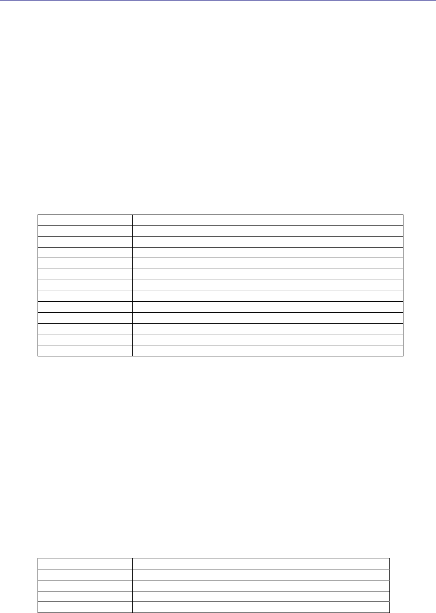
The Versus Information System is a reliable, flexible platform for locating personnel and
equipment. The system badges, worn by staff or attached to assets, emit signals that contain
information about the badge. The information is sent through the sensory network to a host
computer that retrieves the information and translates the data into names of rooms, personnel, and
equipment. Workstations throughout the facility can access the location data with various client
software programs, which can display current locations of personnel and equipment, display
alarms on the monitor, send pager messages, and store data for later use in reports.
System Structure
2.1 Infrared (IR) Tracking
The use of infrared (IR) signals for tracking has distinct advantages, since it allows accurate
locating using signals that will not penetrate walls or floors. A system of strategically placed
sensors receives IR signals as badges move between rooms of a building.
2.2 Radio Frequency (RF) Signals
In addition to the IR signal, a low-power radio frequency (RF) signal is incorporated into some
badges. RF signals penetrate walls and ceilings, allowing the RF signal to act as a backup if the IR
signal is blocked. If the IR signal is blocked and an RF sensor receives the RF signal, the last
known IR location of the badge is shown. RF badges and sensors can also be used for security
purposes at locations where tracking assets is important.
Workstations installed with
client software such as Lis
t
View, Floorplan View, etc.
Dedicated VIS Server installed with
Badge Server, Data Server,
Configuration Utilities and optional
software such as Event Monitor
Versus Technology, Inc.
Hardware and Wiring Installation Guide 5
2.3 System Hardware Components
The Versus Information System is made up of a network of badges, sensors, collectors and
concentrators.
2.3.1 Badges
Badges are worn by personnel or attached to equipment. Badges send infrared (IR) or radio
frequency (RF) signals to the sensors installed in each room. This signal contains encoded digital
information that is used to identify and obtain the status of the badge. Motion, timing, battery
state, and auxiliary information are all included in the signal.
All Versus badges that include IR technology have a unique feature that serves to extend battery
life. They contain a motion-sensing device that causes the badge to transmit most frequently when
in motion and gradually reduce this frequency when there is no motion.
There are several types of badges. Badges can include IR, RF, or IR and RF technology,
depending on the needs of the facility. Some badges also include a button for alarm notification.
Consult the badge specification sheets for more information on battery and component functions.
2.3.1.1 IR Badges
Because IR badges use near-visible light to communicate with the sensors, the signal can be
hidden from the sensors by clothing or obstacles. It is important to be aware that IR badges
should not be covered or hidden from view.
The Locator Badge (VER-1700)
The Locator Badge can be used for locating people or equipment. This
badge is ideal for locating applications where only location is required,
and communication or alert capabilities are not needed.
The Locator Badge sends infrared signals from two emitters located at
the top left and right corners of the badge case. The signals are directed upward and somewhat
forward at a wide angle to be received by the sensors. Better performance occurs by keeping
the badge in an upright position.
• Battery type – Lithium, 3.5 volt, 750 mAH
• IR Wavelength – 875 nanometers, 447.5 KHz
2.3.1.2 IR/RF Badges
In addition to sending IR signals, IR/RF badges send radio frequency signals that are received
by RF sensors.
RF signals are used in a supervisory capacity, in cases when IR signals are hidden from view,
and for sending alarm or call signals triggered by pressing a button on badges that include
buttons.
Versus Technology, Inc.
6 Versus Information System
IR/RF Personnel Alert Badge (VER-1780)
The Personnel Alert Badge uses IR and RF technologies. It is also
equipped with a call button that, when pressed, fires RF and IR signals,
which can notify the system to activate a customizable, preprogrammed
response.
• Battery type – 3.0 V lithium coin cell (industry type CR2477 lithium 950 mAH)
• RF Frequency – 433.9 MHz
• IR wavelength – 875 nanometers, 447.5 KHz
IR/RF Asset Tag (VER-1830 A&B)
The Asset Tag uses IR and RF technology. It is used to identify the
current location of portable assets. VER-1830A has an anti-tamper
feature that sends a signal to the system if the tag is removed from the
asset it is attached to. VER-1830B does not have the anti-tamper feature.
• Battery type – 3.0 V lithium coin cell (industry type CR2477 lithium 950 mAH)
• RF Frequency – 433.9 MHz
• IR wavelength – 875 nanometers, 447.5 KHz
NOTE: The Asset Tag’s anti-tamper and other RF functions can be hindered if the
tag is affixed to metal. Must be used on non-metal surfaces or with a bracket.
2.3.1.3 RF Badges
RF/PAS Asset Tag (VER-1875)
The RF/PAS Asset Tag uses radio frequency (RF) signaling technology in combination with
Versus’ Perimeter Alarm Sentinel (PAS) technology to secure portable assets from
unauthorized removal. The PAS component causes the tag’s RF signal to send an alarm when
entering a PAS zone, thereby signaling unauthorized removal of a tagged item from a specific
area.
• Battery type – 3.0 V lithium coin cell (industry type CR2477 lithium 950 mAH)
• RF Frequency – 433.9 MHz
Must be used in combination with the Versus PAS Unit (VER-3500) which is installed in
portal or doorway areas to create protected PAS zones. See Section 2.3.5 for a description of
the PAS Unit.
NOTE: The PAS Tag’s RF function can be hindered if the tag is affixed to metal.
Must be used on non-metal surfaces or with a bracket.
2.3.2 Sensors
Sensors receive signals from badges, convert them into electrical signals and pass the data along to
collectors. Up to 24 sensors (of which up to 4 can be RF sensors) can be connected to a Collector,
although Versus recommends no more than 20-22 to allow for future expansion. Sensors are
usually mounted in the ceiling tiles of a facility, or they can be placed in standard electrical
junction boxes, where required by local building codes. There are four types of sensors, infrared
(IR), radio frequency (RF), supervised and serial.
Versus Technology, Inc.
Hardware and Wiring Installation Guide 7
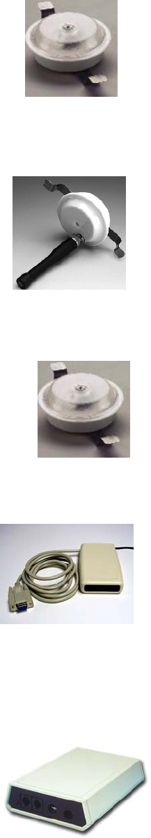
2.3.2.1 Infrared (IR) Sensor (VER-4422)
IR sensors receive IR signals from badges and convert them into electrical
signals. A single unshielded twisted pair type wire transmits the signals to a
Collector and provides the sensor’s operating power.
The maximum run length from an IR sensor to a Collector is 1000 feet. IR
sensors have 360-degree horizontal coverage, 180-degree vertical coverage, and up to 15 feet
radius reception distance.
2.3.2.2 Radio Frequency (RF) Sensor (VER-4450)
RF sensors operate at 433.92 MHz receive frequency. They convert
encoded RF signals emitted by badges into electrical signals, and send
them to Collectors via a single unshielded twisted pair wire.
Note: No more than four RF sensors should be connected to any
one Collector.
2.3.2.3 Supervised IR Sensor (VER-4442)
The Supervised Sensor is a VER-4422 IR sensor with the added ability to
generate its own signal, allowing the VIS to monitor the data delivery to its
Collector. Using one Supervised Sensor per Collector, the VIS can send an
alert if a portion of the sensory network or facility intranet stops sending badge
data. Requires the use of the Collector Checker software (sold with the
Configuration Utilities) and Audio Visual Services software (sold separately).
2.3.2.4 IR Serial Sensor (VER-4444)
The Serial Sensor is an IR Sensor that can be attached to any PC to
create a location zone. Unlike a standard IR sensor, no hardwiring is
necessary. Simply attach it to a computer’s serial port, install the
software, and you have a permanent or temporary location for use with
the VIS. The Serial Sensor’s range is 16 feet in front of the sensor, and
the computer it is attached to must be running in order for it to sense
badges. To accomplish a greater sensing range, you may wire a standard IR sensor to the
Serial Sensor to be used externally. An RF sensor may also be wired to the Serial Sensor.
2.3.3 Collector (VER-2402)
After sensors receive signals from badges and convert them to electrical
signals, the data is passed to a Collector. Up to four Collectors are daisy-
chained together, and then connected to a Concentrator.
Up to 24 sensors can be connected to one Collector, although Versus
recommends no more than 20-22 at initial installation to allow for future
expansion, possibly without having to add additional Collectors. No more
than four RF sensors can be connected to one Collector. The Collector accepts the inputs from the
sensors and assembles the inputs into larger, network-ready packets. The packets are then relayed
to a Concentrator.
Versus Technology, Inc.
8 Versus Information System
A punch-down connector block is included with the Collector. The connector block plugs directly
into the 50-pin connector on the side of the Collector. Sensors connect directly to the Punch-down
Block. The 24V power supply for the Collector is included, as well as mounting supplies.
2.3.4 Ethernet Concentrator (VER-2015)
Ethernet Concentrators receive all data passed through collectors, format
the data, and send it to a computer as a data packet. Up to four collectors
can be connected to one Ethernet Concentrator. Concentrators are
connected to Collectors in a daisy-chain fashion.
2.3.5 Other Optional Hardware
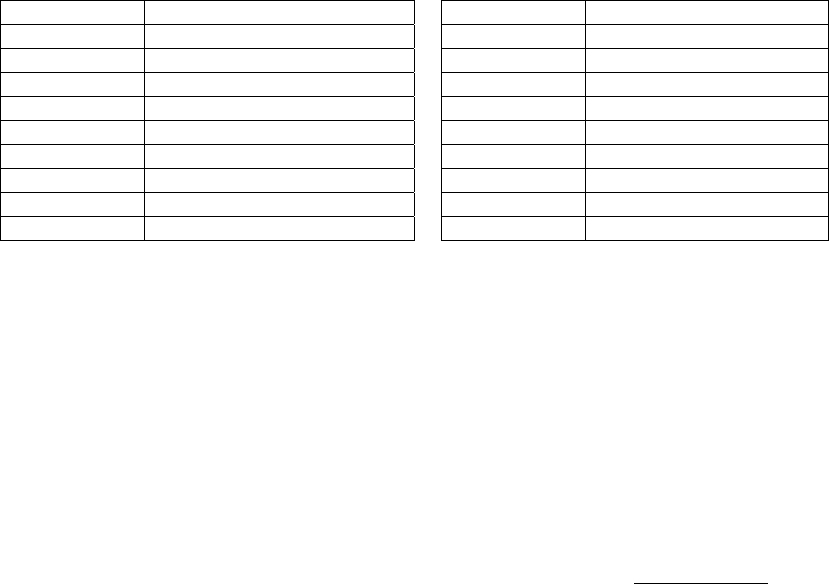
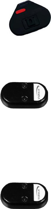
Remote Station (VER-4052 without pull cord, VER-4054 with pull cord)
This small, wireless, radio frequency (RF) device can be mounted on a wall or other
non-metal surface. When the button is pressed, a signal is sent to the system,
notifying it to activate a customizable preprogrammed response. The button lights
up when it is pressed, giving a visual cue that the signal has been sent.
The Remote Station is available with or without a pull cord. The button is available
in clear, red, green or yellow. Clear is not available with light.
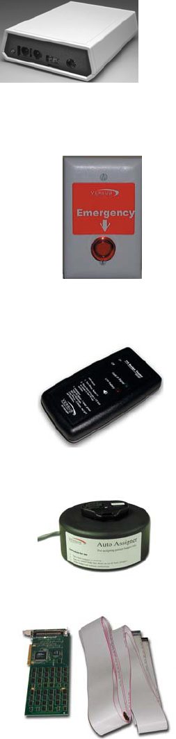
Badge Tester (VER-0004)
A Badge Tester tests the battery and auxiliary information from the badge. It
will indicate whether a valid IR packet is received or if the battery needs to be
replaced. If a valid IR packet is received, the tester will beep once, and the
green light will illuminate. If the battery is low and needs replacing, the tester
will beep twice, and the red light will illuminate.
Auto Assigner (VER-4440)
The Auto Assigner makes the badge assignment process fast and easy. By
placing a Versus IR or combination IR/RF badge under the unit, the VIS Badge
Wizard automatically pops up on the computer screen and fills in the badge
number field without the need to manually type in each badge number during
the assignment process. Requires the Event Monitor software.
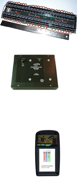
Digital I/O Board (VER-3010)
The Digital I/O Board is used to control relays with the Versus system. It
requires a PCI slot in the computer and room for the board, which is 12
inches in length. Up to five Digital I/O Boards can be installed in one
computer, assuming there are five PCI slots available, to control up to 480
relays. Includes a ribbon cable to connect to two external relay boards.
Requires at least one external relay board (VER-3015).
Versus Technology, Inc.
Hardware and Wiring Installation Guide 9
External Relay Board (VER-3015)
The external relay board controls up to 48 relay-controlled
devices, such as corridor lights, door locks, etc. Two External
Relay Boards can be connected to one Digital I/O Board.
Requires Digital I/O Board (VER-3010).
Perimeter Alarm Sentinel (PAS) (VER-3500)
The PAS unit is ideal for placement at ingress and egress points. The
PAS unit excites the Versus RF/PAS Asset tags to fire radio
frequency signals when within range of the unit (4' – 14'). The
signals are received by a nearby RF sensor and reported to the Versus
Information System or the facility’s access control system via a
Versus Wiegand Converter.
The PAS unit plugs into a 110V electrical outlet using a 14VAC power supply that is provided
with the unit. Used in combination with the RF/PAS Asset Tags (VER-1875) and RF sensors
(VER-4450).
Wiegand Converter (VER-3600)
The Wiegand Converter allows the user to connect Versus infrared (IR) and/or
radio frequency (RF) readers directly to any access control panel that accepts
2601 Wiegand readers. It converts the tag ID received from the Versus reader into
2601 Wiegand format and sends the tag ID to the access control panel’s Wiegand
reader port. The access control system can do whatever it can normally do with
the information, such as send alarms, etc.
Versus Technology, Inc.
10 Versus Information System
3. Planning the Installation
Planning the system design is crucial to the success of the installation. Thorough planning will
make the installation go smoother, and there will be less likelihood of mistakes or oversights.
When planning an installation, certain rules and limitations must be observed. The equipment has
been designed to provide trouble-free operation in various environments, and adherence to the
guidelines is critical for a reliable installation. The following sections will detail items that must
be included in a system plan to ensure a successful installation.
The Installation Checklist, located in Section 6.4, is intended to be a record of the installation
steps. Before starting the installation, fill in the checklist by referring to the contractual floorplan
schematic for the quantities and numbers of zones and other components for the specific
installation. The Punch-down Block Organization List in Section 6.5 will also be used during the
planning stages of the installation.
General System Hardware Configuration

Versus Technology, Inc.
Hardware and Wiring Installation Guide 11
3.1 General Steps for Installing a Versus System
Use this checklist as a guideline for the installation steps. Each step refers to the place in the
manual where there is detailed information on how to perform the step. When planning and
performing the installation, it is important to keep good documentation, especially by using the
Punch-down Block Organization List in Section 6.5. Keeping good documentation keeps the
installation more organized, as well as assisting with configuring the software.
General Hardware Installation Steps
Procedure Step Where to find additional information
1. Plan the installation.
a. Layout the floor plans, mapping the sensor
locations with an identification scheme. Map the
Remote Station and Corridor Light locations as
well, if the system includes them
b. Plan communication room or specified area for
collector and concentrator locations
Hardware and Wiring Installation
Guide, Section 3.
2. Pull sensor and collector cables, making sure to label
both wire ends. Pull Corridor Light cables, if the
system includes them
Hardware and Wiring Installation
Guide, Section 4.1
3. Install sensors
Hardware and Wiring Installation
Guide, Section 4.2
4. Install concentrators, collectors and punch-down
Blocks
Hardware and Wiring Installation
Guide, Section 4.3
5. Connect sensor wires to collectors via the punch-down
blocks
• Fill in Punch-down Block Wire Organization
List
Hardware and Wiring Installation
Guide, Section 4.4
Section 6
6. Test the collectors, sensors and concentrators using
the Communication Room Checklist in Section 6.6
Hardware and Wiring Installation
Guide, Section 4.5
Software Installation and Configuration Steps
Procedure Step Where to find additional
information
1. Pre-Installation Procedure:
a. Computer IP address
b. Note the server’s computer name
c. Share the C drive, Versus directory, or
appropriate folders needed for software
Badge Server and Data Server
Configuration Manual, Section 2
2. Install the Concentrator Software Badge Server and Data Server
Configuration Manual, Section 3.1
3. Assign IP addresses to the Concentrators for the
network environment
Badge Server and Data Server
Configuration Manual, Section 3.2
4. Change the IP address of the server back to the
original
Badge Server and Data Server
Configuration Manual, Section 3.3

Versus Technology, Inc.
12 Versus Information System
5. Connect the Concentrators to the Network Badge Server and Data Server
Configuration Manual, Section 3.4
6. Add the Concentrator Numbers to the Badge Server Badge Server and Data Server
Configuration Manual, Section 3.5.1
7. Install the Data Server Badge Server and Data Server
Configuration Manual, Section 4.1
8. Start the Data Server Badge Server and Data Server
Configuration Manual, Section 4.2.1
9. Configure the Data Server
Badge Server and Data Server
Configuration Manual, Section 4.2
10. Install Configuration Utilities on Server for database
configuration
Configuration Utilities Manual, Section 2
11. Configure sensors and collectors in the Sensors and
Receivers Utility
a. Add room names
b. Add Collectors
c. Map Rooms to Collectors and Sensors,
making sure to note RF sensors in the Type
column
Configuration Utilities Manual, Section 3
12. Add badge types in the Badge Type Utility
• Add patient, caregivers, wall badges, and
any other badge types needed
Configuration Utilities Manual,
Section 4
13. Test locations using Walking Setup Configuration Utilities Manual,
Section 3.7
14. Set up other Configuration Utilities as needed Configuration Utilities Manual
15. Install client software on workstations
Individual client manuals
16. If the system includes RF sensors, test them using
the Frequencer (TCP/IP)
Hardware and Wiring Installation Guide
Section 4.7 and Badge Server and Data
Server Configuration Manual, Section
5.1
17. Create Backup
• Most important file to back up is the
pdcs.mdb file
Configuration Utilities Manual, Section
13.4
18. Verify system by checking off Punch-down Block
Organization List, Relay Light List, and
Communication Room checklist
Hardware and Wiring Installation Guide
Section 6
19. Final install checklist including training information Hardware and Wiring Installation Guide,
Section 6
Versus Technology, Inc.
Hardware and Wiring Installation Guide 13
3.2 Collector and Concentrator Location Planning
When planning an installation, it is important to locate a proper place for the concentrators and
collectors. Collectors should be mounted in telephone or service areas that are near the sensory
networks they service. The sensor wires will run from the collectors to the various sensor locations
throughout the facility. The concentrator(s) should be mounted in a location central to the
collector(s) to minimize the length of collector network runs. In smaller installations, collectors
and concentrators may all be located in the same place in a telephone or utility closet. The location
selected should have easy access for servicing, but be secure against tampering by unauthorized
personnel. Make sure the locations selected are free from extremes of heat, cold and moisture, as
with any electronic equipment.
Caution: Collectors may be affected by high watt radio or paging antennas. Do not
place a collector in close proximity to one of these antennas.
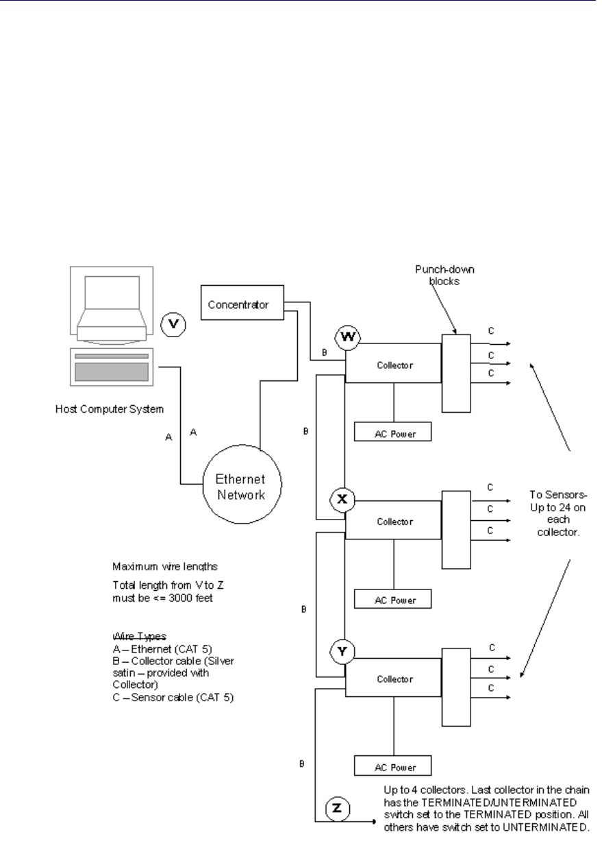
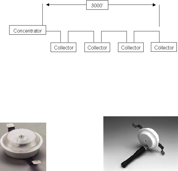
3.2.1 Collector Network Length Limitations
There must be no more than four collectors on any one concentrator as shown in the RS-485 loop
display below. Collectors should not be placed more than 1000 feet apart. The total length of the
collector network (from the Concentrator to the last Collector in the chain) must not be more than
3000 feet.
3.3 Sensor Location Planning
One of the most important steps in an installation is planning the sensor locations. A complete
understanding of sensors and badges is very helpful in designing an effective system. There are
several things to consider when planning the sensor locations.
IR Sensor RF Sensor
Versus Technology, Inc.
14 Versus Information System
3.3.1 Sensor Connection Length Limitations
The sensor wire runs can be up to 1000 feet in length from the Collector to the sensor. If the
environment is known to be electrically “noisy,” consider shorter line lengths for stronger signals
and immunity to interference.
3.3.2 Infrared (IR) Sensor Location Planning
Several factors will determine where you install IR sensors, including the sensors’ field-of-view,
effective or overlapping coverage, and possible interference from sunlight, plasma screens,
lighting and EMI noise.
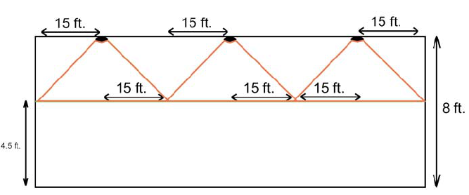
3.3.2.1 IR Sensor “field-of-view”
If an IR sensor is placed in a room with obstacles and reflections eliminated, the field of view
of the sensor appears in the shape of six overlapping lobes forming a 15-foot radius.
The 30-foot diameter cone of coverage was determined based on the sensor being placed in
an 8 foot ceiling and the badge being approximately 4.5 feet off the ground.
An IR sensor “sees” the environment under it in a largely predictable pattern. However, there
are factors that can affect this field of view. The sensor is like an eye, which is sensitive only
to a narrow spectrum of light, and the signals from a badge appear as a bright splash in an
otherwise dark world to the sensor. Even if the badge is blocked from the view of a sensor, it
can often be detected. The infrared light from a badge does not penetrate solid objects or bend
around corners, but it does reflect off surfaces. This can sometimes be mistaken for “seeing
around corners.” The effect of reflection can be used to advantage by the system designer, but
can also pose problems if the installer is unaware of it. Sensors have a given field of view
when obstacles are not present, but the field of view of an installed sensor will vary due to
room configurations.
A sensor may have a field of view that extends out of the designated area through a doorway
or passage. This can cause badges to be detected incorrectly and reported to be in the room
when only passing by. Place sensors near the middle of rooms, but offset from doors or
entryways to prevent false detection. The position of a sensor can limit its view by placing it
in a location where existing obstacles will block any unwanted sensor view.
Versus Technology, Inc.
Hardware and Wiring Installation Guide 15
Due to the line-of-sight nature of the infrared light created by the ID badges, it is also possible to
apply masking to the sensor to limit or control the field of view by opening the sensor case and
placing electrical tape over the receiver “eye” whose field of view needs to be blocked. However,
proper placement is always the preferred method for controlling, rather than eliminating, sensor
field of view.
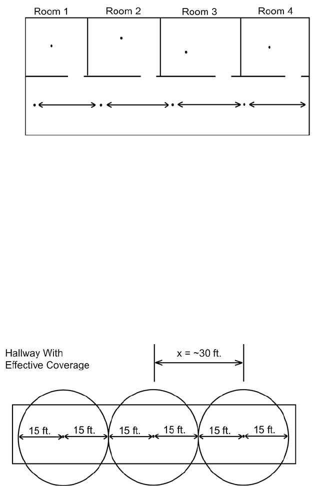
3.3.2.2 Effective coverage of rooms
A single sensor placed near the middle of the ceiling can usually effectively cover an office or
meeting room. A single sensor generally covers offices or rooms as large as approximately 30
feet square. The sensor should be located so that it has the best possible view of the room. If
the room is very large or has a complex shape and no single sensor position will provide
adequate coverage, multiple sensors will be needed. For effective coverage, place sensors
approximately 30 feet apart.
3.3.2.3 Overlapping Sensors
Sensor overlap occurs when two (or more) sensors are placed so that their fields of view
overlap. This will cause some indecision in the system if both sensors see a badge at the same
time. The software will not change the location of a badge when it is in an overlap area unless
the option to send duplicate hits is selected in the Badge Server software. If the option is
selected, a badge may appear to bounce back and forth as long as it is in an overlap condition.
This increases the traffic on the system and it is not recommended that the option be selected.
Versus Technology, Inc.
16 Versus Information System
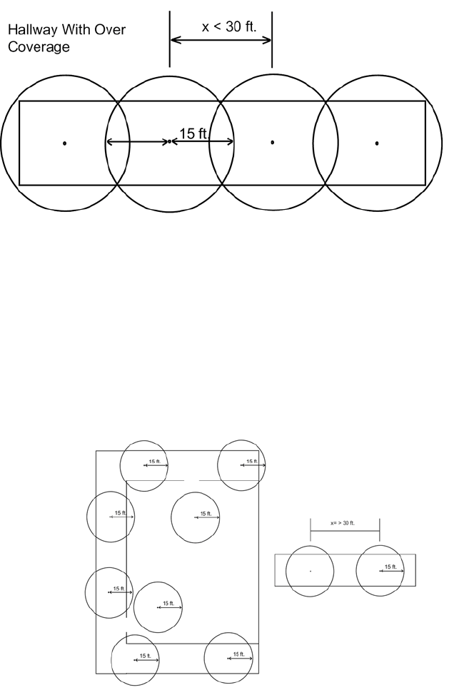
3.3.2.4 Sensor Spacing Coverage
A technique for spacing sensors more then 30 feet apart may be effective for long hallways
and for big rooms. This technique is primarily used for equipment tracking applications. The
technique uses the idea that when a tag enters a location zone, it is there until it leaves that
location zone. The VIS system can map many sensors to the same location zone (see the
example sensor layout below for sensor spacing greater then 30 feet). The sensor spacing is
critical for knowing where the tag is located. You will see areas in the hallways and in the big
room where there is no sensor coverage. However, the system layout was designed to pick up
the badge as it enters and leaves location zone areas.
3.3.2.5 Sunlight Interference
If a room has windows that allow a large amount of sunlight to enter the room, place the
sensor in a position where the sunlight does not hit it directly or reflect into it from objects in
the room. Sunlight can decrease sensor range and field of view if allowed to enter the sensor.
Window tint films that block infrared (heat) energy greatly reduce this effect.
3.3.2.6 Plasma Screen IR Interference
The VIS locating system utilizes infrared (IR) light with a wavelength of approximately 880
nanometers. Versus IR sensors “read” IR badge signatures by detecting digitized IR light
Versus Technology, Inc.
Hardware and Wiring Installation Guide 17
pulses produced by the badge.
Large plasma computer displays (such as the NEC 42MP2) emit large quantities of IR,
including IR light in the 880-nanometer wavelength. Like visible light, these inadvertent
emissions bounce off any reflective surfaces such as walls, floors, doors, etc., effectively
“flooding” the immediate area with 880-nanometer IR light.
Much like attempting to read white print on white paper, distinguishing the low-power IR
light of the VIS badge from intense background IR light becomes impossible in such an
environment.
Versus recommends that IR sensors not be installed in proximity to plasma screens. Because
the emissions vary greatly depending on the size and manufacturer of these displays, Versus
recommends allowing excess sensor wire and then testing the effectiveness of any sensors to
be installed near one of these displays prior to permanently mounting the sensor in the ceiling.
3.3.2.7 IR Sensor Interference From Nearby Lighting or EMI Noise
System performance can be adversely affected by;
1. Light that is aimed directly into the sensor.
2. EMI noise emitted by nearby electrical fixtures.
3. Light fixtures that hang below the sensor and shine directly up into the sensor.
Symptoms of sensor interference are:
1. A voltage drop below 15.5 volts.
2. Badges that are not picked up by the sensor or only picked up intermittently.
Do not mount sensors near lights or electrical fixtures unless absolutely necessary. If the
performance of an IR sensor is in question, move the sensor as far away from any nearby
lights or electrical fixtures as is practical. If the light fixtures are causing problems, try
mounting the sensors off the ends of the fixtures if you can’t move them fair enough away.
To avoid problems with light interference:
If sensors must be mounted near lights;
1. Mount sensor as far from the light as possible
2. Mount sensor so that the light does not have a direct path into the sensor “eyes.”
3. As a last resort, mask the eyes of the sensor that are receiving the direct light, using
electrical tape. (Caution: this disables the sensor operation in that direction).
4. Mount sensors so that light fixture is not below the sensors.
To avoid problems with EMI noise:
1. Do not mount IR sensors near suspect fixtures.
2. Do not run sensor connection cables near suspect fixtures.
3.3.3 RF Sensor Location Planning
Planning the location of RF sensors depends upon the facility. In most cases, for complete
coverage, they can be placed approximately 100 feet apart, because they have a sensitivity range
radius of approximately 50 feet. However, because concrete and steel structures absorb the RF
signal, and other materials affect the strength of RF signals, testing is necessary to determine the
best placement of RF sensors. When possible, avoid placing RF sensors in areas with an
overabundance of electrical devices, such as in a room with many computers.
Versus Technology, Inc.
18 Versus Information System
In multi-floor facilities, it is desirable to stagger locations. For example, to achieve better
coverage, do not place the sensor on the third floor directly above the sensor on the second floor.
If using the VIS to track assets with the Asset Tag (VER-1830) or RF/PAS Tag (VER-1875), the
required placement of these tags may affect the number of RF sensors needed to achieve effective
coverage. If the tags must be placed near a metal surface or are offset from a metal surface by a
bracket, the RF signal emitted may be reduced in strength due to absorption by the metal. In these
cases, more RF sensors may be needed to compensate for the lack of RF signal. If you plan to
mount Asset or PAS tags near a metal surface, contact Versus Technology for more information
on appropriate RF coverage.
Important: Each Collector should have no more than four RF sensors connected to it.
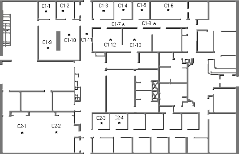
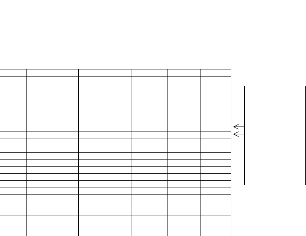
3.3.4 Mapping the Sensor Locations on the Floorplan
The sensor locations should be mapped out on a floorplan diagram of the facility. These are the
locations where the sensor cable will be run. We suggest using a numbering scheme such as C1-1,
C1-2, C1-3, C2-1, C2-2, C2-3 etc., where “C1” represents Collector 1 and “C2” represents
Collector 2. Up to 24 sensors can be connected to one collector, although we recommend 20-22 to
allow for future expansion. The wires should be labeled at both ends with these numbers as well.
The facility must provide a list with the names of the rooms. The room names will be used for
configuring software. Once the sensors have been mapped with identification numbers, and the
facility has provided a list of names of the rooms, complete the Punch-down Block Organization
Chart (located in Section 6.5) with the number and the room name. You should also add the
receiver numbers, which will be used for configuring the software. Number the receivers with
incrementing numbers (1, 2, 3…). If there is more than one IR sensor in a particular area, they
may be assigned the same receiver number if you choose, but it is not necessary. Under normal
circumstances, do not assign an RF sensor and an IR sensor the same receiver number unless you
are using the PAS system (contact Versus for more information). When assigning RF sensors,
Versus recommends adding an RF designation to the description. See the following example chart.
Versus Technology, Inc.
Hardware and Wiring Installation Guide 19
Punch-down Block Wire Organization List
Collector #: 3265458142
Collector alias: C1
A copy of this chart is located in Section 6.5 and can be printed for your use. Use one chart for
each collector on the system. Each successive chart should have room/receiver numbers starting
with the next incremental number from where the previous chart left off. Using this chart will
assist you with labeling cable wires appropriately.
3.3.5 Mapping the Relay Device Locations
If the system includes relay-controlled devices, such as corridor lights or door locks, they should
be mapped out on the floor plan of the facility. We suggest a numbering scheme such as R1-1, R1-
2, R1-3, etc. Label each end of the wires to the relay-controlled devices with the same numbers. In
addition, you will need to document the relay numbers and relay cable IDs on the Punch-down
Block Organization List located in Section 6.5. For each room on the list that will have a corridor
light installed, enter its numerical position on the relay board, starting at 0. In addition, there is a
Relay Board Organization List in Section 6.8 for mapping the relay board with the appropriate
room names and light colors. When you connect the relay wires to the relay board, you will need
to refer to the list and connect them accordingly. The two-page form has numbers 0-47 on the first
page and 48-95 on the second representing two relay boards with 48 relays each. Use one two-
page form for each relay controller board.
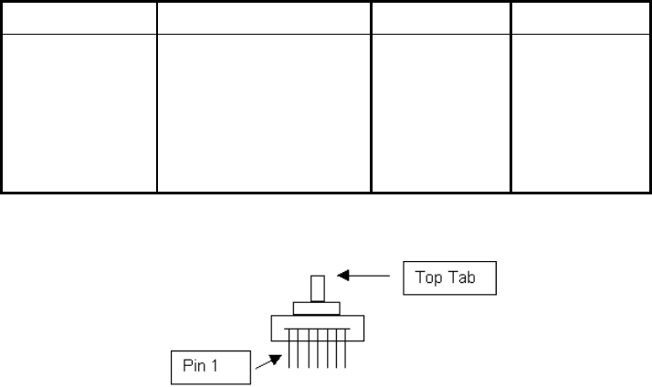
Punch-
down
block
pair Cable ID
Wire
Color
Zone description
(room name)
Receiver/
Room # Relay # Verified
1 C1-1 John’s Office 1
2 C1-2 Bob’s Office 2
3 C1-3 Patient Room 120 3 0,1,2,3
4 C1-4 Patient Room 122 4 4,5,6,7
5 C1-5 Patient Room 124 5 8,9,10,11
6 C1-6 Patient Room 125 6 12,13,14,15
7 C1-7 Hallway 7
8 C1-8 Hallway 7
9 C1-9 Nurse’s Station 8
10 C1-10 Nurse’s Station 8
11 C1-11 RF Nurse Station 9
12 C1-12
13 C1-13
14 C1-14
15 C1-15
16 C1-16
17 C1-17
18 C1-18
19 C1-19
20 C1-20
21 C1-21
22 C1-22
23 C1-23
24 C1-24
Building: Main Facility
Floor: 1st
Room #: Comm. Room 1
If there is more
than 1 IR sensor
in a room or area,
you can give them
the same receiver
number, but
unless you are
using the PAS
system, do not
assign an RF and
IR sensor the
same receiver
number.

Versus Technology, Inc.
20 Versus Information System
Assign an ID number to the relay boards. All the relay boards connected to one computer will
have the same number. We suggest a small label on the relay board with a number, such as 5000
for all relay boards connected to the first computer, 5001 for all the relay boards connected to the
second computer, etc. The actual number assigned is not important, but the number will be used
later when configuring the software. Write this number on the Relay Board Organization List in
Section 6.8 for reference when configuring the software.
3.4 Use of Unauthorized Components
The VIS system integrates hardware and software to create a safe, reliable and efficient system.
Use of components or connection to equipment not approved by the manufacturer is NOT
recommended and will invalidate all warranties.
Approved third-party components include wire and connectors, terminal blocks, and other
interconnection means only. Questions regarding the use of third-party equipment or components
should be directed to your dealer for clarification before being connected to your system.
3.5 List of Recommended Tools
Some installation activities require special tools. Following is a list of recommended tools.
Cable Stripper
Cordless Drill
Diagonal Clippers
Digital Multi-Meter
Electric Screw Driver
Ethernet Supplies
Fishtape
Hole Saw 2 3/8” Drill Attachment
Level
Mounting Screws
Nut Drivers
Punch-down Block Tool-Type 66 or Bix,
whichever is a
pp
ro
p
riate
RJ-45 Testers
RJ Connector Terminator Tool Kit
Scissors
Screwdriver Assortment
Splice Crimp Tool
Small Hammer
Electrical Tape
Tape Measure
Twist Ties
Utility Knife
UY Connectors
Vise Grip Pliers
Walkie Talkies (helpful for testing sensors)

Versus Technology, Inc.
Hardware and Wiring Installation Guide 21
Weidmeuller Patch Check Plus
Wire Strippers
3.6 Safety and Code Considerations
Safety procedures and adherence to local building codes are the responsibility of the system
installer. Versus products have been designed to be safe and reliable under the conditions in which
they are intended to be used. The following sections detail those aspects of the system that might
affect safety.
3.6.1 Equipment Handling
The components used in a typical installation contain internal circuits that are sensitive to static
electricity. Static electricity transported by the human body may be strong enough to damage
internal circuitry during installation. These components do not normally have exposed connector
pins, but if handling with exposed connectors or pins is required, the installer should use an anti-
static wristband connected to an electrical ground. This is especially important when temporarily
disconnecting and reconnecting cables. The badges are the only system components that people
can come in direct contact with. Therefore, cleaning the badges after each use is recommended. A
badge should be thoroughly cleaned after each use, and wiped down with a disinfectant. The
disinfectant should be alcohol-based, not water-based. Do not immerse or autoclave badges.
Warning:
Avoid touching bare contacts or connector pins when handling system components in
order to prevent the accidental transfer of static to internal devices. Leave protective
covers attached during installation.
3.6.2 Power Requirements
The components obtain low-voltage operating power from a local wall mounted “plug-in”
transformer. Transformers provided with the systems are Underwriter Laboratory (UL) approved.
No components use 120V AC line power directly, except the computer systems.
Warning:
Do not attempt to connect or disconnect concentrators, collectors, sensors, or any
other system components with power applied. The hardware may be damaged.
Although damage will not occur in most cases, this practice is not recommended
and may void equipment warranties. Use of powering schemes not approved by the
manufacturer will void equipment warranties.
As with any electrical equipment, safety is a prime concern. The system poses no safety hazard,
since it uses only low-voltage DC power. However, installers must take adequate precautions to
ensure that the low-voltage wires are not exposed to high-voltage electrical wires, and that wires
run through ceilings and walls do not encounter dangerous electrical potentials and carry them to
points where they might be exposed to human contact.
No powering device other than the plug-in units provided should be connected to the system
without prior authorization from the manufacturer.
Versus Technology, Inc.
22 Versus Information System
3.6.3 Grounding of Equipment
All points in a system installation are connected to a common “ground” via their interconnect
wires. No attempt should be made to provide any additional earth ground or neutral connections to
any sensor or collector. Adding ground connections to multiple points in a networked system may
introduce electrical system noises that will interfere with normal system operation. Consult the
manufacturer if special grounding requirements must be met.
CAUTION: Allowing sensor or network conductors to encounter metal surfaces and
structures, or allowing wires to be routed in close proximity to high-
powered equipment or devices will introduce electrical interference and
may cause erratic operation and/or equipment failure.
EXCEPTION: For interference on the collector cable, see Section 4.5.4.1 for more
information on making the CAT 5 cable.
3.6.4 Codes and Ratings of Materials Used
The materials used in the construction of individual components meet or exceed UL fire retarding
requirements. However, not all these devices are rated for air plenum use. They are intended for
utility closet mounting and must not be placed in airways or plenum areas, unless they can be
housed in approved enclosures and sealed to meet local codes.
Installers must be aware of local fire and health codes in their selection of interconnect wiring.
Plenum-rated wire and cable must be used where it will pass through breathable air spaces. Wire
and cable rated for plenum use will be clearly marked. For information regarding plenum cabling,
call Versus Technology, Inc. Manufacturing Department.
3.6.5 Workmanship
The following standards of workmanship must be followed during installation:
• National and local building codes must be followed.
• Tools used must be as recommended by the manufacturer, or approved equivalents.
• Connections must be made with manufacturer’s recommended tools and procedures.
• Conductors must not be nicked nor wire strands cut during wire stripping.
• Wire bundles must be neatly dressed.
• Wire bundles must be spaced away from power cables and lighting.

Versus Technology, Inc.
Hardware and Wiring Installation Guide 23
4. System Hardware Installation
This section covers the installation of the system components. Before installing the hardware
components, all planning should be completed as described in Section 3.
For instructions on installing relay boards or corridor lights, refer to Sections 4.8 and 4.9.
4.1 Cable Installation
When installing sensor and network wiring, use normal telephone installation techniques. Sensor
wire runs should allow sufficient length to move ceiling tiles and to move sensors if needed.
It is the responsibility of the installer to run all cables as indicated on the floor plan schematic
diagram. Each cable must be labeled at both ends with the identification of the end device to
which it is connected. Use the same numbering scheme for sensors as described in the previous
section, referring to the Punch-down Block Organization List (C1-1, C1-2, C1-3, etc.). Label
collector cables with the identification of the collector that it runs to down the collector chain,
away from the Concentrator.
4.1.1 Cable Types
Versus Technology recommends the following cable types for installing hardware components:
Sensor Cable UTP CAT 3 is acceptable, Versus recommends CAT 5
Collector Cable Versus provides a silver satin cable to daisy-chain Collectors and
connect the last Collector to the Concentrator. If longer distance is
needed between Collectors, or if Collectors are in proximity to
high electrical interference, CAT 5 cable is needed. See Section
4.5.4.1 for more information on making the CAT 5 cable.
Ethernet Cable CAT 5
Approved equivalent cable types may be used.
4.2 Sensor Installation
Handle the sensors with care to not scratch or damage the casing.
Warning:
Always disconnect power from the system before connecting or disconnecting
components. Failure to do so may damage the equipment.
The UTP wire runs from the punch-down/collector to a sensor mounted in ceiling tile. Only a
single pair of wire is required for each sensor. No grounding at the sensor is required.
Sensor installation calls for use of a splice connector at the sensor end of the cable run. Sensor
wires have no polarity and can be connected to sensor wire-pairs in either order. In the case of
two-pair UTP cable, the same pair must be used at each end of the sensor run. It is suggested that
blue wire be used for consistency. Up to four sensors may be used on each CAT 5 cable if
preferred, although using one cable per sensor makes troubleshooting easier.
Versus Technology, Inc.
24 Versus Information System
To install and wire sensors:
1. Referring to the floor plan schematic diagram, identify sensor locations and verify
identification numbers.
2. Create a hole for the sensor in ceiling tile or ceiling surface using a 2-3/8" hole saw.
3. Pull the sensor cable wire-pair through the hole and connect to the sensor using UY
splice connectors.
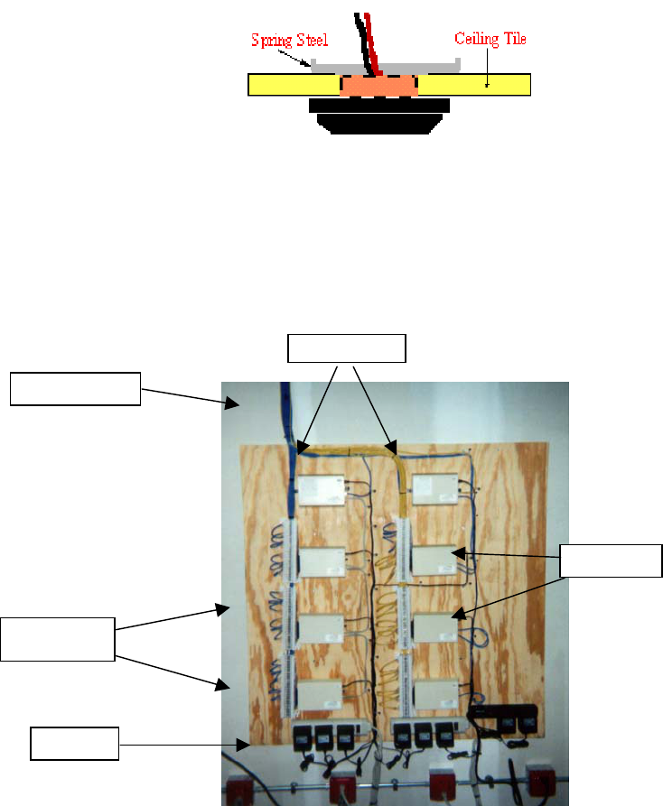
4. Gently bend the spring steel clips upward and insert the sensor into the ceiling tile hole.
The steel clips and the sensor cover will “sandwich” the ceiling tile and hold securely.
5. Mark the sensor as installed on the floor plan diagram or Punch-down Block Wire
Organization List.
4.3 Collector and Concentrator Installation
An example of neatly installed punch-down blocks, collectors, and concentrators.
The punch-down blocks, collectors, and concentrators should be installed in a secure location,
such as a communication or server room. The installation should allow for wiring access, neat
Concentrators
Punch-down
Blocks
Collectors
24V AC
Sensor wires
Versus Technology, Inc.
Hardware and Wiring Installation Guide 25
wire routing and dress, and connection of any sensor wire-pair to any collector input. Neat and
orderly punch-down blocks are easier to troubleshoot and maintain.
To install the Collectors and Punch-down Blocks
Note: Make sure power is not supplied when connecting components.
1. Mount the punch-down block on the wall using appropriate wall-mount hardware.
2. Mount the collector adjacent and connected to the associated punch-down block, using
the Velcro tape and clip provided with the unit. When using Velcro tape to secure a
collector unit, make sure the solid metal end clip is firmly secure to prevent sagging of
the connection between the collector and punch-down block.
To install the Concentrator(s)
The Concentrator is a “table-top” box assembly, which can sit on a level surface or be mounted on
any flat surface with mounting clips. Mount all concentrators as indicated on the floor plan
schematic diagram.
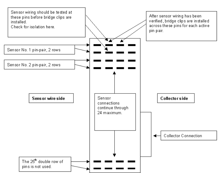
4.4 Connecting Sensors to Collectors
Sensors are connected to the collectors through punch-down blocks. The punch-down block is
organized so that each two punch-down block rows, starting at the top left of the block, are one
collector port that is connected to by one sensor.
Bridge-clips are used to connect left-side pins to the right-side pins, which are wired to the
collector unit. If patching of sensor inputs is required, jumpers can be used from any sensor wire-
pair on the left to any collector wire-pair on the right.
Make sure power is not supplied when connecting components.
Versus Technology, Inc.
26 Versus Information System
Punch-down Block
To connect the sensors to the punch-down block:
Note: Connect no more than four RF sensors to a Collector. Up to 24 sensors total can be
connected to a Collector.
For connecting the sensor wires to the punch-down block, refer to the Punch-down Block
Organization Chart for the location each wire should be connected on the block.
1. Remove all bridge clips from the punch-down block.
2. Referring to the Punch-down Block Organization List to make sure each sensor wire
is connected to the correct position on the punch-down block, connect the sensor
wire-pairs to the appropriate punch-down block pin-pair positions using the punch-
down block tool.
3. Check isolation.
This is necessary because in the course of interconnecting many sensors to a
collector, it is not uncommon to make contact with a sharp metal edge, ganged
knockout box, or electrical ground with one of the conductors. It is critical, however,
that such accidental connections be located and cleared before applying power to the
system. The effect of these accidental connections can range from mild to severe. In
Versus Technology, Inc.
Hardware and Wiring Installation Guide 27
many cases, erratic behavior may be noted. In some cases, equipment damage may
occur. In any case, an electrical code violation has occurred.
To verify that the system is “isolated” from building and electrical
grounds:
Note: It may be helpful to disconnect the collector from the punch-down
block while this measurement is made. This will isolate the sensor wiring
completely.
a) Use an ohmmeter or multimeter set to the 2K (2000)-ohm scale.
b) Clip one probe to the nearest electrical conduit or electrical ground.
c) Touch the other probe to each punch-down block row in turn.
d) Every row MUST indicate an infinite (open) connection. If this is not
the case, the suspect line must be traced to find the accidental
connection to the structure that has been made.
4. Once isolation has been checked, replace the bridge clips on the punch-down block.
4.5 Communication Room Check
There are several items that need to be verified before applying power to the system. Use the
Communication Room Checklist in Section 6.6 to check off each step as it is completed.
4.5.1 Checking the Collector Wiring
A visual check of the collector wiring should find the punch-down block secure and the collector
unit connector firmly seated against the punch-down block connector. See the Collector Voltage
Troubleshooting Flow Chart in Section 5.2 for checking the collector wiring.
Caution: Always test all wiring before connection of system power sources.
The collector network (2-pair) must be tested before the system power is applied to be sure that
wires are not misconnected. Failure to thoroughly test the collector network wiring may result in
equipment damage.
The concentrator and collector devices connect to the 2-pair wiring system using modular
interfaces to allow for easy testing of the wiring before power is applied. It is recommended that
installers be equipped with appropriate USOC cable testers as required to verify the installed
wiring.
Note that 3-pair USOC interconnections may also be used. In this case, the third pair (outermost)
is used in parallel with the second pair to improve power distribution to the collectors.
Versus Technology, Inc.
28 Versus Information System
4.5.2 Terminating the Last Collector
The Collectors on the Versus Information System are connected by wires run from unit to unit in a
daisy-chain fashion and carry high speed digital data to the Concentrators. It is critical that the
electrical energy running through the Collector wires is absorbed at the end and does not “bounce
back” down the wire and cause interference with other data coming through. To absorb the energy,
the wire must be ended with a resistor on the last Collector in the chain, terminating the
transmission of data.
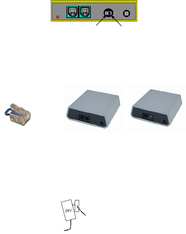
Two models of the Collector exist, each with a different method of termination. The old style
collectors are equipped with a switch that must be turned to the Terminated position on the last
Collector in the daisy-chain, as shown below.
Terminated Unterminated
It is very important that the collectors which are NOT at the end of the line have this switch set to
the UNTERMINATED position, and that the collector which is at the end of the line has this
switch set to the TERMINATED position.
The new style Collectors are considered unterminated until a termination shunt is placed in one of
the two jacks on the unit. A termination shunt is shipped with each Collector, but only those at the
end of the daisy-chain will need to be terminated.
4.5.3 Testing Sensor Voltage
Collectors are included with a 24V power supply that must be used for each collector, providing
local operating power. No other power supply is adequate to power collectors. To ensure the
power supplies do not pull out by their own weight, either mount the power strip outlet side up or
use wire ties to hold the power supply in place.
Power supply
may become
disconnected if
power strip is
mounted
sideways.
Use wire ties to hold the
power supply in place.
Termination Shunt
Unterminated Collector Terminated Collector

Versus Technology, Inc.
Hardware and Wiring Installation Guide 29
When the collector wiring and isolation have been verified, and the cable connection between the
concentrator and the collector has been tested and found correct, the next step is to apply power to
the collector and check the sensor connections for the correct voltages.
► To test sensor voltage
Once power has been applied to the collector, a voltmeter check should be made of the sensors on
the punch-down block to verify that they are connected correctly.
1. Set the voltmeter or multimeter to a 20-volt range.
2. Apply the probes to each sensor connection on the punch-down block.
If the reading is: For: (Sensor type) Then:
Approximately 16 volts IR The sensor is wired correctly.
Approximately 18 volts RF The sensor is wired correctly.
<14 volts IR and RF There is radio frequency or
electromagnetic interference.
Approximately 20 volts IR and RF There is no sensor connected to this
pair or the wiring to the sensor is open.
Very low or zero IR and RF
The sensor pair is shorted. (The 25th
pair on the punch-down block is
unused and will read zero volts.)
When the voltmeter is applied to a sensor pair, a slight drop in voltage can be observed when
the sensor is receiving a transmitting ID badge.
3. Check RF interference by switching the meter to the AC scale and reading the voltage. With
no badge transmitting over the sensor there should be < 0.1 VAC on a sensor pair.
Caution!
A shorted sensor pair will not cause immediate damage to the collector. However, if allowed
to remain, some heating of collector components will occur, which is undesirable. If shorted
pairs are found in the sensor voltage test, remove the collector power and resolve the short
as soon as possible. If the system must be powered with the short unresolved, remove the
punch-down block bridging clips to disable the disruptive sensor until the wiring can be
repaired.
4.5.4 Connecting Collectors and Concentrators
There are two parallel RJ receptacles on each collector. This allows collectors to be chained
together from the concentrator to the last collector in the chain.
With each Collector, Versus provides a silver satin cable with an RJ-12 modular jack (6 wire) to
daisy chain Collectors and connect the last Collector to the Concentrator. If longer distance is
needed between Collectors, or if Collectors are in proximity to high electrical interference, CAT 5
cable is needed.
Versus Technology, Inc.
30 Versus Information System
4.5.4.1 Making a Collector Wire if CAT 5 Cable is Needed
If the silver satin cables included with the Collectors cannot be used due to the distance
between the Collectors or because of possible high electrical interference, connector cables
will need to be made with CAT 5 cable. Cables should be tested prior to applying power. It is
recommended that installers are equipped with appropriate cable testers to verify the wiring.
A key indication of connector problems with the collector cable is the red indicator light on
the collectors, which may indicate a short circuit. The red light will flash every time it sees a
badge fire. A constant pattern of four or five flashes may indicate there is a problem with the
connectors on the cable.
To wire collectors
Note: Do not make any connections to components unless indicated by a step in the
procedure. Ensure that all bridge clips have been removed from the selected punch-
down block/collector unit.
1. Refer to the contractual floor plan schematic diagram and identify the collector and
concentrator locations.
2. Attach an RJ connector to each end of the collector cable, as shown below.
Collector RJ-12 Plug Wire Colors:
Plu
g
Pin No. CAT 5 Wire Colo
r
Descri
p
tio
V
olta
g
e
1
NOT USED
2 N
O
T
US
ED
3
Whi
te/
Bl
ue
D
ata
(
+
)
0
-
5
VD
C
4 Bl
ue
D
ata
(
-
)
0
-
5
VD
C
5
Whi
te/O
r
a
n
ge
G
r
ou
n
d
0
VD
C
6
O
r
a
n
ge
G
r
ou
n
d
0
VD
C
Note: With connector pins pointing toward you, cable away from you, pin 1 is to the left.
3. Using the Weidmeuller Patch Check Plus test set or an equivalent model, perform the
following steps to verify straight through continuity for each collector cable run:
a) Plug one end of the cable into the receiver unit of the test set.
b) Set the reset switch on the receiver unit to the “On” position.
c) Plug the other end of the cable into the Transmitter unit of the test set.
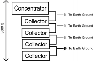
Versus Technology, Inc.
Hardware and Wiring Installation Guide 31
d) Set the reset switch on the transmitter unit to the “On” position. All the red LEDs
will light followed by an audible squawk tone.
e) Touch the TEST button on the transmitter. After a short delay, the transmit #1
LED will light with the corresponding #1 LED on the receiver scale.
f) Touch the TEST button again to light the transmit #2 LED with its corresponding
receiver #2 LED.
g) Repeat this process until all conductors in the cable have been verified for
continuity.
4. For each collector perform the following:
a) For the collectors identified on the contractual floor plan schematic diagram as
LAST, set the UNTERMINATED/TERMINATED switch to the
TERMINATED position. For all other collectors, set the switch to
UNTERMINATED.
b) Insert the RJ plug(s) into the collector receptacle(s) (either collector receptacle is
acceptable).
In case of interference problems with the collector cable over a long distance, it may be necessary
to ground the cable to an earth ground. You will need to use a shielded CAT 5 cable between the
interference points. Depending upon interference, the collector wire should be grounded to an
earth ground. This should only be done if there is known interference on the collector cable.
4.5.5 Network Wiring for Ethernet Concentrators
The computer should be equipped with an appropriate network card for connecting to the Ethernet
Concentrator(s).
The Ethernet Concentrator requires CAT 5 four-pair UTP cable runs between the network card in
the computer and the Ethernet Concentrator. For multiple concentrators, install a 10Base-T or
10x100Base-T network hub or connect it to an existing Ethernet network within a facility. The
Concentrator cannot be connected to a 100Base-T network hub. Like Collectors, Ethernet
Concentrators use a 24V power supply. For more information on the Ethernet Concentrator, refer
to the Badge Server and Database Server manual.
4.5.6 Concentrator Power-up Test
When the wiring has been examined and the power supply voltage has been found to be in range, a
power up of the concentrator may be performed to verify its operation. The Concentrator power
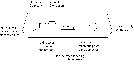
Versus Technology, Inc.
32 Versus Information System
supply should be secured to the electrical outlet using a screw or cable ties to ensure that it cannot
fall out or be disconnected by others working in the same area.
Caution!
Disconnect the modular cable from any down channel collector(s) and allow it to remain
disconnected during the test. Down channel collectors could be damaged if power is
applied before they have been checked.
Plug the power supply connector into the concentrator and observe the red LED indicator lights. If
it fails to light, recheck the power and connections.
There are four LED indicator lights on the Concentrator. The function of each is described in the
diagram below.
Ethernet Concentrator
The LED indicator light on the Collector will blink every time it receives badge data from the
sensors. If the LED blinks in a four- or five-blink pattern, this indicates it is not communicating
with the concentrator. If this is the case, there is a problem with either the network cable
connection or the connection to the concentrator. If the LED blinks in a three-blink pattern, this
indicates a problem with the collector, and it should be sent to Versus Technology for repair.
4.6 Walking Setup Test
After the Database Server, Badge Server and Configuration Utilities have been installed, you
should perform a walking setup of the system to verify sensor locations. The Badge Server and
Database Server Manual describes the installation and configuration of the Badge Server and
Database Server. The Configuration Utilities Manual includes adding collectors, adding room
locations, matching up the sensors with locations, and testing them with the walking setup.
4.7 Testing RF Sensors
The Frequencer is a utility that shows data being received by sensors. Data can be filtered to show
only information for a specific badge or sensor. The Frequencer is instrumental in testing that all
areas of the facility are covered by RF sensors.
To test RF sensor coverage:
1. Open the Frequencer, which is installed to the Versus\IRTools directory. The file is
TCPFreq.exe.
Versus Technology, Inc.
Hardware and Wiring Installation Guide 33
2. On the Frequencer screen in the Server IP field, type the IP address of the computer
where the Badge Server is installed. The badge hits will start appearing in the window.
3. To isolate and only test RF sensors, type the badge number of an RF badge in the Badge
field.
4. Take the RF badge and “hide” the badge in a pocket or other place, so it is not seen by
the IR sensors.
5. One person will need to sit at the computer while another person walks to all areas within
the facility with the hidden badge. Both will need walkie-talkies to communicate.
6. Have the person with the badge walk around the facility and press the badge button at
different locations. You will see the hits in the Total Time, Total Hits, and Avg. Time
fields.
7. Verify that the badge is seen in all locations by the RF sensors, especially areas such as
bathrooms, where there may be no IR coverage.
8. Mark the area as covered on the Punch-down Block Organization List.
4.8 Relay Board Installation
The digital I/O board is installed into a PCI slot on the computer that will be running relays. The
external relay board should be mounted in a metal utility box in a secure location such as a
communication or server room. The external relay boards need to be installed within 10 feet of the
computer where the digital I/O board is installed. This is because the 50-pin ribbon cable
connecting them is 10 feet in length.
A 50 pin ribbon cable connects the external relay board to the PCI slot of the comptuter where the
PCI-DIO96H Digital I/O Board is installed. One Digital I/O Board can accommodate up to 2
external CIO-ERB48 relay boards. One computer can have up to five PCI-DIO96H relay cards,
assuming there are five PCI slots available in the computer.
The relay devices are powered by the computer power supply.
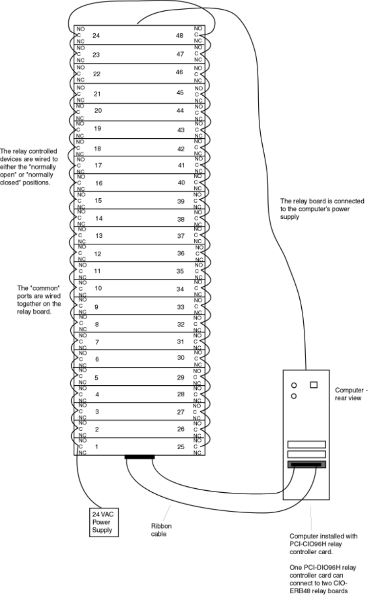
Versus Technology, Inc.
34 Versus Information System
An example of wiring the relay board
Versus Technology, Inc.
Hardware and Wiring Installation Guide 35
4.8.1 Power Requirements
The relay board requires a 24VAC power supply. The watts needed varies with the type of relay
controller device being used.
To calculate watts needed:
If you know the number of watts each device needs, you can calculate total watts needed by
multiplying the number of devices times the watts needed by each.
If you do not know the watts that each device needs, but you know the amps needed by each
device, you can calculate the number of watts needed as follows:
The number of amps required by each device multiplied by the number of devices
multiplied by the volts (24V).
Example:
If using lights, and each light requires .04 amps, there are 48 lights on the relay board,
and the power supply is 24V, the calculation is:
.04 amps x 48 lights x 24V = 46.08 watts or more required.
4.8.2 Wire Size Determination
The designer must be sure the last device on the circuit has sufficient voltage to operate the device
within its rated voltage. When calculating the voltage available to the last device, it is necessary to
consider the voltage drop due to the resistance of the wire. The thicker the wire, the less the
voltage drop. Generally, for purposes of determining the wire size necessary for the system, it is
best to consider all of the devices as “lumped” on the end of the supply circuit (simulates “worst
case”).
Typical wire size resistance:
18 AWG solid Approximately 8 ohms/1000 ft.
16 AWG solid Approximately 5 ohms/1000 ft.
14 AWG solid Approximately 3 ohms/1000 ft.
12 AWG solid Approximately 2 ohms/1000 ft.
Example: Assume you have 10 devices on a zone and each requires 50 mA average and 2000 ft.
of 14 AWG wiring (total length = outgoing + return). The voltage at the end of the loop is 0.050
amps per device x 10 devices x 3 ohms/1000 ft. x 2000 ft. = 3 volt drop.
If you have a power supply that is 20 volts, each device runs at 18 volts, according to this
calculation you are under voltage by 1 volt.
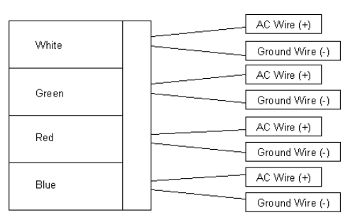
Versus Technology, Inc.
36 Versus Information System
4.9 Corridor Light Installation
Mount the corridor lights using appropriate wall-mount hardware.
Each relay has two wires, an AC power wire and a ground wire. A four-light block has eight
wires.
Corridor light
The wires connecting the corridor lights to the relay board should be 18-gauge stranded unshielded
wire.
The ground wires run from the corridor light to the 24VAC power supply. You can connect the
four ground wires together and run one wire back to the power supply. The AC power wires are
run to the relay board. The wires are connected to the “normally open” (NO) slot on each relay.
The corridor lights are powered by a 24V AC power supply connected into one of the “common”
(C) ports. Then, each common port is wired to the next common port on the relay board. See the
relay board diagram in section 4.8.
4.10 Badge/Tag Wearing and Mounting
Badges are worn by personnel or attached to equipment. The badge signal contains encoded digital
information that is used to identify and obtain the status of the badge. Motion, timing, battery state
and auxiliary information are all included in the signal. Because IR badges use near-visible light
to communicate with the sensors, the signal can be hidden from the sensors by clothing or
obstacles. It is important to be aware that IR badges should not be covered or hidden from view.
RF signals are used for supervisory capacity, in the case where IR signals are hidden from view,
and for sending alarm or call signals triggered by pressing a button on badges that include buttons.
There are several types of badges. Badges can include infrared (IR), radio frequency (RF), or IR
and RF technology, depending on the needs of the facility. Some badges also include a button for
alarm notification. Consult the badge specification sheets for more information on battery and
component functions.
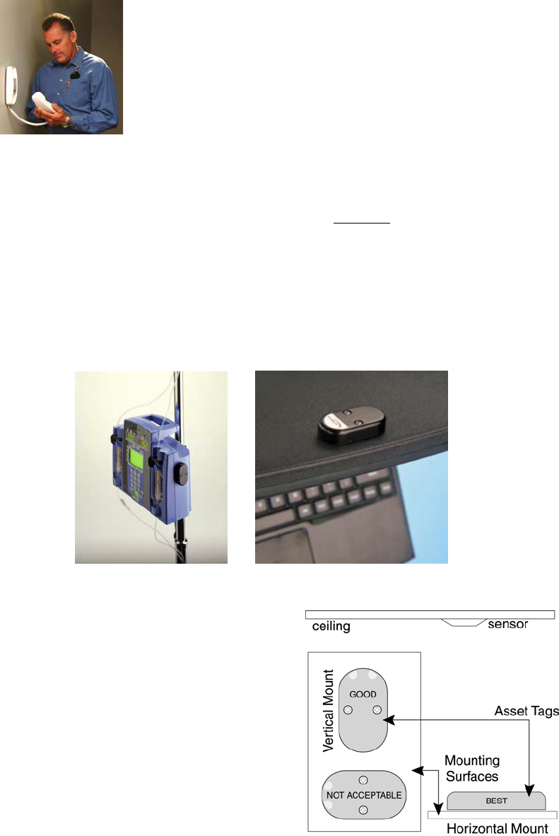
Versus Technology, Inc.
Hardware and Wiring Installation Guide 37
4.10.1 Proper Wearing of the Versus Personnel Alert Badge
To ensure the sensors receive accurate, consistent signals, badges should
not be covered and should be worn as high up on the body as possible,
either on the collar or in the shoulder area. Make sure the signal is not
hidden from the sensors by clothing or obstacles.
4.10.2 Proper Mounting of the Versus Asset Tag
The Versus Asset Tag must be mounted on a flat, inflexible non-metal surface. Mounting the tag
on metal will interfere with its RF performance, limiting the RF signal range. If a suitable non-
metal spot cannot be found for use with the tag, contact Versus Technology to discuss using a
mounting bracket with the tag. Mounting positions should be tested using the Frequencer before
all tags are applied.
The are where the tag is mounted should have a clear view of the IR sensors. The battery should
not be installed until after the tag has been affixed to the asset.
The tag should be mounted horizontally whenever
possible, so that its face is pointing toward the
sensors. If it cannot be mounted horizontally, it may
be mounted vertically so that the IR windows, two
clear areas at the top of the tag, are facing upwards.
DO NOT mount the tag with the IR windows facing
down or sideways.
Vertical Ali
g
nment Horizontal Ali
g
nment
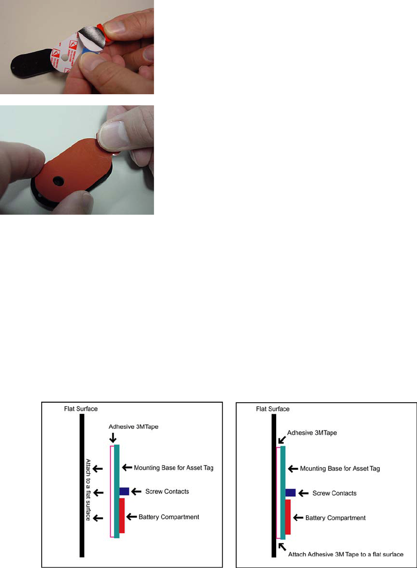
Versus Technology, Inc.
38 Versus Information System
1. Thoroughly clean the mounting surface with an alcohol swab
of a 50/50 or 50/70 isopropyl alcohol/water solution,
removing all dirt and grime. Failure to complete this step
will cause the adhesion to fail.
2. Wipe the surface dry with a lint-free cloth or napkin. Be
sure that no fibers are left behind on the surface.
3. Peel off one liner side of the adhesive tape. Be sure to use the
pull tabs and tape liners to prevent contaminating the
adhesive tape with skin residues.
4. Position the tape over the asset tag base, making sure the anti-
tamper button fits through the provided hole. Using your
thumb, apply pressure over the entire base to seal the tape.
5. When ready to mount the tag to the asset, remove the second
liner using the pull tab. Do not touch the adhesive surface or
you will compromise the adhesive ability of the tape.
6. Apply the tag base firmly to the cleaned area of the asset to
allow the adhesive tape to bond with the surface. A silicone hand exercise ball can distribute pressure
evenly. Once applied, remove the tag’s cover and leave the tag undisturbed for as long as possible
(preferably at least eight hours) to allow the adhesive to cure. Some surfaces may require a 72 hour cure
period to achieve satisfactory adhesion.
7. After the cure time has expired, install the battery and case cover. The battery and cover should be
installed only after the base is affixed to the mounting surface and the cure time has expired. Failure
to follow this procedure may result in the tag lifting and decreased battery life.
3M does not warrant that VHB will adhere to all materials and surfaces but rather specifies that
you must test the surface that you intend to attach the tag. If the above instructions are followed
and the VHB will not remain adhered to the asset over time, the tag must be attached using
conventional fasteners.
Step
3
Step
4
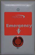
Versus Technology, Inc.
Hardware and Wiring Installation Guide 39
4.10.3 Proper Mounting of the Versus Remote Station
This small, wireless, radio frequency (RF) device can be mounted on or in a wall
or some other non-metal surface. When the button is pressed, a signal is sent to
the system, notifying it to activate a customizable preprogrammed response. The
button lights up when it is pressed, giving a visual cue that the signal has been
sent.
The remote station is designed around a single gang face plate, device box and a
back mounting plate. The face plate is attached to the device box by two security
screws. This device can be mounted in or on the wall or other surface.
To install on a wall or other non-metal surface, verify the correct orientation required and then
mount the back mounting plate to the desired wall or other surface. Attach the device box to the
back mounting plate. Install the battery and tighten with the provided Velcro straps until the
battery is secure. Attach the face plate to the device box with the security screws. To test the
remote station, verify that the button lights up when the button is pushed.
To install in a wall, verify the correct orientation required. The wall should have a plastic gang
box installed. Install the battery and tighten with the provided Velcro straps, until the battery is
secure. Attach the face plate to the plastic gang box in the wall with the appropriate length screws.
To test the remote station, verify that the button lights up when the button is pushed.

Versus Technology, Inc.
40 Versus Information System
5. Troubleshooting Guide
These are possible hardware scenarios and solution issues that may affect the operation of the
tracking system. The Collector Voltage Troubleshooting Flow Chart and the Functionality Test
Flow Chart are included as troubleshooting strategies for correcting system hardware problems.
Problem: System will not start up.
Discussion: Most system failures on startup are caused by failure to properly crimp RJ Type
connectors, along with failure to test the completed connection.
Problem: Collector cannot be seen by the Concentrator on the Subnet.
Discussion: If a collector works properly when unconnected to the subnet, on powering on, it
blinks four to five times every five or so seconds. Once connected to the concentrator’s subnet,
upon power on, the collector light should come on strong after the first few seconds and then blink
only upon receipt of a badge ID.
Problem: Incorrect voltages across sensor pair at the punch-down block.
Discussion: The voltage across the sensor pair at the collector punch-down block should be
between 15 and 17 volts DC. A voltage above 18 may indicate an open circuit, while a voltage
below 15 may indicate RF interference, or faulty sensor, or faulty wiring. RF interference may be
verified by switching the meter to the AC scale and reading voltage. With no badge IDs being sent
down the sensor pair, any AC voltage reading may indicate RF interference.
Problem: RF interference.
Discussion: RF interference may be checked as discussed above. Possible RF interference that
affects the sensor network includes certain types of energy efficient lighting and associated
electronic ballasts. The most common offenders are classified as T8 lights and have an electronic
ballast in the 40 kHz range. Sensor wiring should not touch electrical conduit or ceiling grates, as
they are very good at picking up RF frequencies.
Problem: Sensor not picking up ID from badge (non-working sensor).
Discussion: Smoke detectors using IR detection interfere with Versus sensors. The sensor should
not be installed within two feet of smoke detectors to avoid any interference.
Problem: Collector mounting failures.
Discussion: Collector mounting failures can be avoided by using the mounting clip provided to
hold the end of the collector firmly against the wall.
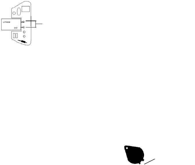
Versus Technology, Inc.
Hardware and Wiring Installation Guide 41
5.1 Badge Battery Replacement
Warning! A low battery may affect system performance. Change low batteries at first
indication.
Note: Static electricity can damage batteries. When changing badge batteries, it is
critical to be grounded, such as by using a static strap and an Electro-Static Device mat
to protect from any shock that would damage the battery or the badge.
5.1.1 Locator Badge (VER-1700)
Battery type: Lithium, 3.5V 750 mAH
1. Place the Locator badge face down on an anti-static mat.
2. Using a small Phillips head screwdriver, remove the screw and back cover of the badge, and
flip the badge over to remove the circuit board.
3. To remove the old battery, grasp the battery with your thumb and forefinger, and gently lift
the battery straight up, being careful to not remove the connector rings (brass inserts) from
inside the battery ports on the circuit board. If the connector rings are removed, the battery
will not make a solid connection.
If a connector ring does pull out with the battery, push it back into the battery port before
replacing with a new battery.
4. Insert the new battery prongs straight into the battery ports, making sure the battery prongs
are firmly seated.
5. Replace the cover and gently tighten the badge screw.
5.1.2 Personnel Alert Badge (VER-1780)
Battery type: 3V Lithium CR2477 950 mAH
1. Locate the screw on the back of the badge. Using a small Phillips head screwdriver (or
security screwdriver), remove the screw and battery cover.
2. Place the battery in the battery compartment with the + facing up.
3. Replace the battery cover, making sure to insert the tabs first.
4. Replace the screw.
Tabs on battery
cover.
Connector rings
are inside the
battery ports.
Versus Technology, Inc.
42 Versus Information System
5.1.3 Asset Tag (VER-1830)
Battery type: 3V Lithium CR2477 950 mAH
1. With a Phillips head screwdriver, remove the screws on the badge.
2. Remove the top portion of the badge.
3. Place the battery in the battery compartment, matching the positive side with the marking on
the tag case.
4. Replace the top portion of the badge and screws.
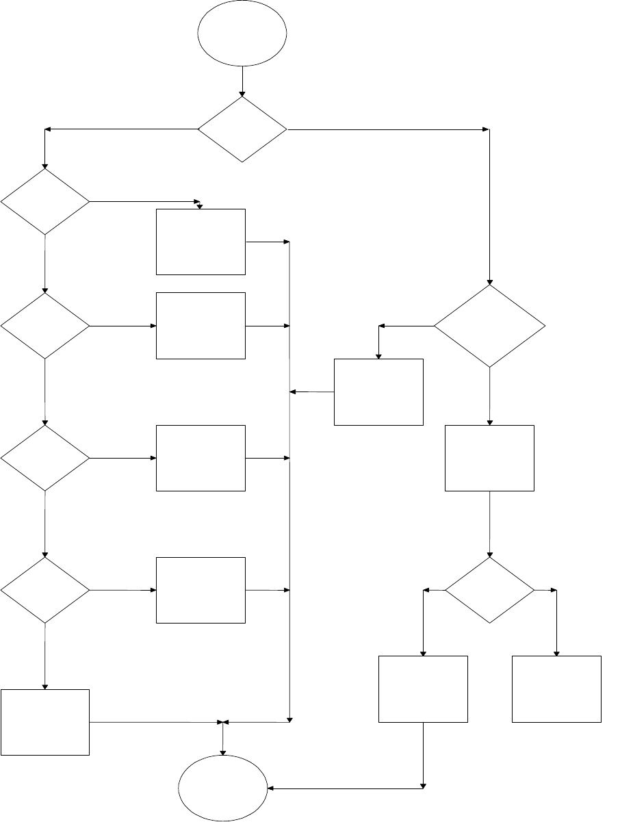
Versus Technology, Inc.
Hardware and Wiring Installation Guide 43
5.2 Collector Voltage Troubleshooting Flowchart
Replace Sensor
Collector
Volta
g
e
Level Low
or Hi
g
h?
Replace collector
Volta
g
e Level <15 Volts Dc
No
Yes
No
No
Volta
g
e Level >17 Volts Dc
Chec
k
Sesnor for
EMI
Sensor Wire
too close to
ceiling tile
railin
g
Sensor too
close to
Hi
g
h fre
q
.
li
g
ht
Re
p
lace Collector
No
Goto
Voltage Test
Move Wire
Move Sensor
Yes
Yes
Check for O
p
en
Wires between
sensor &
p
unchdown
bloc
k
Check
Collector
Volta
g
e
Levels
Replace Collector Done
Fix or Replace
Wire
Yes
No
Good Votage Levels
Bad Voltage Levels
Collector Voltage Troubleshooting
Flow Chart
Volta
g
e
Test
Chec
k
Sesnor for
wires
shorted
to
g
ether
Fix wirin
g
Yes
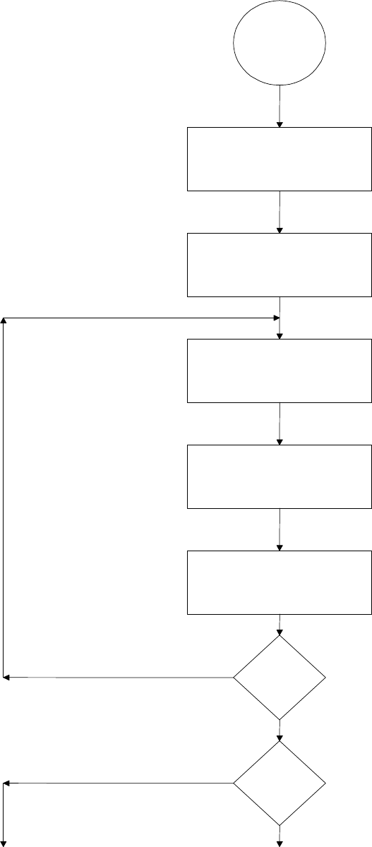
Versus Technology, Inc.
44 Versus Information System
5.3 Functionality Test Flow Chart
Functionality
Test
Choose a sensor Location
Start Frequency Program
Start in the middle of the sensor, walk
out at 6" intervals with a badge four
feet off the floor.
Record these readings
Repeat reading around
sensor at 30 degree
intervals.
Next Sensor
A
re there
any dead
spots
Goto Light Test Page
Check another Sensor
Done
Done

Versus Technology, Inc.
Hardware and Wiring Installation Guide 45
6. Installation Forms
This section includes forms for testing and installation purposes.
Forms
6.1 Computer Setup form
6.2 Installation Plan
6.3 Final Verification
6.4 Installation Checklist
6.5 Punch-down Block Wire Organization List
6.6 Communication Room Checklist
6.7 Preventative Maintenance Inspection Report
6.8 Relay Board Organization List

Hardware and Wiring Installation Guide 47
6.1 Computer Setup
Customer: Date:
Operating System Processor & Speed RAM RAID Type: Server/Client
Computer Settings Versus Set Customer Changed
Computer Identification
Domain
IP Address
Subnet
Computer Passwords Username Password
Administrator
User
User
User
Software Name Version Software Name Version
1 7
2 8
3 9
4 10
5 11
6 12
Setup: Special Setup Criteria
1 Power features set to NEVER
2
3
4
Options: Type Yes/No/NA
Backup
Remote Access
Anti-Virus
Restrictions
Security
Other Specifications:
Hardware and Wiring Installation Guide 49
6.2 Installation Plan
Customer Name:
Customer PO #(s): ______________________________________________________________
Sensors:________________________________RF Sensors: ____________________________
Collectors:_________________________________________ Room & Location Names Required
Ethernet Concentrators: _________________________________________ IP Address Required
Badges: __________ Qty: _______ ; __________ Qty: _______ ; ____________ Qty: _______
Software:______________________________________________________________________
_____________________________________________________________________________
Additional Information: (i.e. badge drawer, focused sensors, relays…these require additional time)
Time Estimates:
1. # of installation days by contractor: ______
2. # of verification days by Versus Technology ______ * crew size of ___ _______
3. # of training hours ______ * crew size of ___ _______
4. # of on-site configuration ______ * crew size of ___ _______
5. Total Versus Installation _______
Required: PO, Install Checklist, and Proposal/Quote
Floorplan(s): Sensor Placement Drawings
Installation: Begin Date___/___/____ End Date ___/___/___
Requirements for Installation:
Room Keys
ID Badges
Support Contacts/Personnel w/phone #s
1.
2.
3.
Installer company and contact name:________________________________________________
(Versus or outside contracting familiar with regulations)
Floorplan(s) to Installers with Wiring Specification and if needed site visit
Hardware and Wiring Installation Manual
Wiring Specifications
Component List
Punch-down Block Wiring List
Communication Room Checklist
Relay Board Organization List
Sensors, collectors, concentrators, wiring installed and mounted correctly
Required facility sign off of contractors work
Versus verification of installation work
Communication Room Check List
Floorplans
Punchdown Block Wiring
Relay Board Organization
Installation Plan page 1 of 3
Hardware and Wiring Installation Guide 51
Versus Computer Server Setup: # of Computers _______
Check Requirements
Jazz Drive
Additional Hardware components:
PC Anywhere Software
Versus Software:
Anti-virus software:
Facility Software & Hardware Requirements:
Required Room/Location Names:
Computer Room Location(s) for server(s):
Phone line or TCP/IP routing services Password Required:
IP Addresses for all network devices
Software Client locations
Develop Badge/Tag Types:
Network Requirements:
Identification of Computers
Domain
IP Address
Subnet
Default Gateway
DNS Host Name
DNS Domain
DNS Services
WINS Address Primary
Secondary
Check: Enable DNS for Windows Resolution
Uncheck: Enable LMHosts Lookup
On-Site Configuration
System Hardware Testing completed see final installation Comm Room Checklist
Software Setup: Configuration of Sensors & Room Names and Collectors
Computer passwords
Username: ___________________ Password: ___________________
Username: ___________________ Password: ___________________
Username: ___________________ Password: ___________________
Software/system backup
Sensor Software Verification (Walk Around with Training)
Using the Software Training
Assigning Badges
How to wear a badge
How the system works training
Who is responsible for the system communication i.e. where do I ask my questions
How to change batteries option
How to send back RMAs
Additional Planning: (Additional configuration or time issues)
Installation Plan page 2 of 3

Hardware and Wiring Installation Guide 53
Training
1. General Usage by End User - Low Level Training # 1
• Different Views
• Badge Assignment
Date Who
2. Training for Supervisory trainers - Medium Level Training # 2
• How the System Works / Components
• Different Views
• Badge Assignment
• Application Flows
Date Who
3. Overall Key Operations for overall system administrator - High Level Training # 3
• How the System Works / Components
• Location of Hardware Components
• Ethernet / Network Knowledge
• Different Views
• Configuration Utilities including Badge Assignment
• Application Flow
• Troubleshooting
• Backup Procedures
• Clearing Out Logs
• Overall System Maintenance
Date Who
Final Customer Sign off:
Final Verification Check off required: see Final Verification sheet
Installation Plan page 3 of 3

Hardware and Wiring Installation Guide 55
6.3 Final Verification
Final verification and sign off for: ___________________________________________
Primary responsible party: _____________________ ________________________
(Name) (Signature)
PO Verification Check
1. The hardware components: Collectors _______, Ethernet Concentrator
____, Sensors & Wiring ______ and computer(s) _______have been
installed and are acceptable
2. Training on backup procedures and preventive maintenance including
battery replacement has occurred to appropriate responsible party (see
below # 7)
3. Software CD has been issued and installed and clients are acceptable
4. Software & Hardware documentation have been issued and explained
5. Support & Troubleshooting have been covered (see #6 below)
6. Training has occurred to appropriate personnel and everyone is aware of their
current responsibilities:
_________________________________ _____________________________
(Primary Responsible Party) (Signature)
7. Customer’s Designated Support Contacts
a. System administrator: ____________________ ____________ ___________
(Name & Title) (Phone #) (E-mail)
b. Support contact: ________________________ ___________ ___________
(Name & Title) (Phone #) (E-mail)
8. The Versus System is working correctly according to contractual agreement
__________________________ __________________________ ___________
(System Administrator) (Signature) (Date)
__________________________ __________________________ ___________
(Primary Responsible Party) (Signature) (Date)
__________________________ __________________________ ___________
(Versus Representative) (Signature) (Date)

Hardware and Wiring Installation Guide 57
6.4 Installation Checklist
The table and inspection report in this section will be used to indicate the completed installation and test of
hardware and wiring. The installation codes will be as follows:
C = Cable checked I = Installed hardware
Make copies of the table and enter the numbers of the hardware as they are installed. Indicate a cable check
completion with a “C” and a hardware installation completion with an “I” in each numbered cell of the
table. The installer will be directed by the steps of the installation to make these entries as the checks and
installation are made.
Copies of the entries should be kept with other installation documentation.
Item Quantity Hardware
Installation
System
Installation
Installation Hardware
Sensor Cable
Collector Cable
UY connectors
UR connectors
Network Cable
Cable Labels
Cable ties
RJ 12
RJ 45 (for shielded cable use shielded RJ 45
connectors)
Versus Products
IR Sensors (VER-4422)
RF Sensors (VER-4450)
Supervised IR Sensor (VER-4442)
IR Serial Sensor (VER-4444)
Remote Stations (VER-4052)
Remote Stations (VER-4054)
Collectors (VER-2402)
Concentrator (VER-2015)
Locator Badges (VER-1700)
Personnel Badges (VER-1780)
Asset Tags IR/RF Anti-Tamper (VER-1830A)
Asset Tags IR/RF (VER-1830B)
Digital I/O Board (VER-3010)
External Relay Board (VER-3015)
Software Licenses
Software Backups
Installation Checklist page 1 of 2

Other optional tools –
depending on installation
Quantity Hardware
Installation
System
Installation
Sensor Splice Crimp Tool
Punch-down Tool - Type 66
RJ Connector Terminator Tool Kit
Ethernet Connector Terminator Tool Kit
Ethernet Supplies
Electric Screwdriver
Cable Stripper
Screwdriver Assortment - Incl’ Small
Nutdriver Assortment - Incl’ ASM Sizes
Diagonal Clippers - Small & Large
Digital Multi-Meter
Utility Knife
Flashlight
Visegrip Pliers
Small Hammer
Cordless Drill
2 3/8” Hole Saw
Fishtape
Center Punch
Step-Drill
Knock-Out Punch
Installation Checklist page 2 of 2

Hardware and Wiring Installation Guide 59
6.5 Punch-down Block Wire Organization List
Collector # _______________________
Collector Alias _______________________
Punch-
down
block
pair
Cable
ID
Wire
Color Zone description (room name)
Receiver/
Room #
Relay
#
Relay
Cable
ID
Remote
Station
ID Verified
1
2
3
4
5
6
7
8
9
10
11
12
13
14
15
16
17
18
19
20
21
22
23
24
Building: ______________________
Floor: ______________________
Room #: ______________________
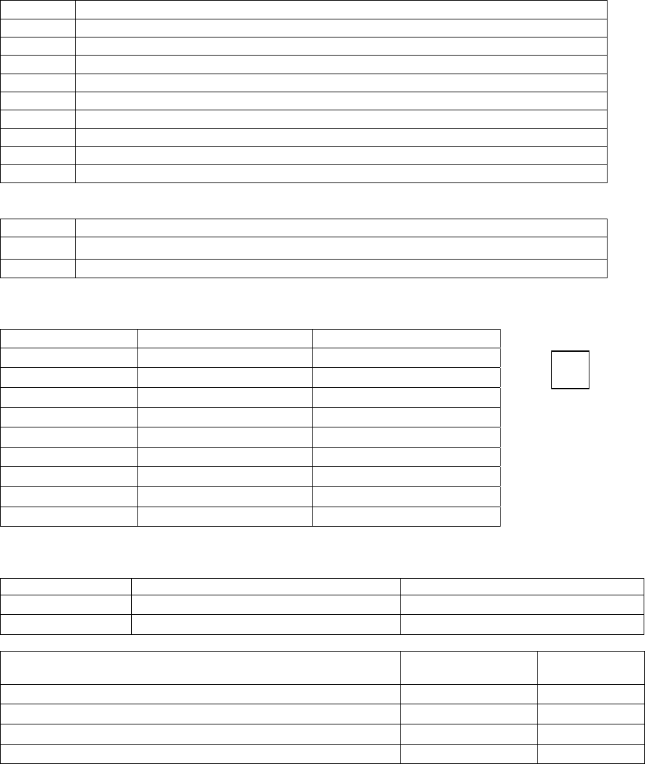
Hardware and Wiring Installation Guide 61
6.6 Communication Room Checklist
Floor: _________ Location/Room #: ______________________________
Check Installation Verification
Check Power Strip Mounting
Check 50 Pin Connector Status to Punch-down Block
Hub/Port Availability
Network Cable installed/Continuity Test
Ethernet Concentrator Administered
Collector Voltage Testing ~ 15.5 to 16.9
Collector Termination
Collector Cabling
Concentrator Room Label Information
Optional
Collector Layout Sheet
Relay Unit Configuration
Computer Setup and Hardware Configuration
Number of Collectors: ____________
C# Identification # Termination
Number of Ethernet Concentrators: _________
Port/Hub # IP Address # ID #
Additional Comments: Fixed Date
______________________________________________ ___________________
(Installation Person) (Date)
Powered up

Hardware and Wiring Installation Guide 63
6.7 Preventative Maintenance Inspection Report
Customer ______________________________ Customer Number______________________ Date___________
Call Number___________________________
Equipment Serial Number _________________ Software Revision _________
Configuration (!)
___ Host Computer Setup ___ Collector Setup ___ Software Intellimotion 3-Pack
___ Pager Computer Setup
(Optional)
___ Punch-down Block
Configuration
___ Software Pager (Optional)
___ Work Station Computer
(Optional)
___ Concentrator Setup (Optional) ___ Software Misc. (Optional)
___ Network Wiring ___ Sensors ___ Sensor Wiring
___ ASM (Optional) ___ ASM Audio Wiring
(Optional)
Tools
1. Standard hand tools 3. RJ Tester 4, 6 & 8 Pins 5. ESD Mat and Wrist Strap
2. Multimeter 4. Hardware & Software Manuals
Visual Inspection (!)
Inspect the following for excess wear and/or any visual signs of damage.
1. ___ General 4. ___ Reseat socketed
Components/connectors
7. ___ ASM Mounting
2. ___ Computers 5. ___ Connectors 8. ___ Cable insulation
3. ___ Concentrator Mounting 6. ___ Sensor Mounting 9. ___ Collector Mounting
Cleaning (!)
1. ___ Clean all internals of dust 4. ___ Clean sensor work area(s) 7. ___ Clean infrared tag
2. ___ Clean external surfaces 5. ___ Clean ASM work area(s)
3. ___ Clean ASM Area 6. ___ Clean All computer stations
Calibration (!)
1. ___ N/A
Electrical Safety Checks (!)
1. ___ Wall Receptacle Test
2. ___ Sensor Voltage Test
3. ___ Collector RJ Line Continuity Test
Preventative Maintenance Report page 1 of 2

Hardware and Wiring Installation Guide 65
Checkout Procedure (!)
System Computers Concentrator
___ Connections Sensor/ASM ___ Software Setup ___ Connection between Computers and
Network (Optional)
___ Display ___ Startup and Restart
___ Intercom Modules ___ PC Anywhere &
Modem
___ Network
Collectors Sensors ASM
___ Wiring Punch-down ___ Sensor Test Software ___ LED Power ON
___ Mounting ___ Voltage Check ___ Intercom Connections
___ Random flashing Red LED ___ Software Move Test ___ ASM Test Software
Battery Install Backups Training
___ Battery Installation ___ Backup Data from
Computer Install
___ Completed
___ Tracking on System
___ Activates Page (Optional)
Preventative Maintenance Report page 2 of 2
Hardware and Wiring Installation Guide 67
Wire Color Light Color
Punch-
block
position
Room name Verified
Wire Color Light Color
Punch-
block
position
Room name Verified
Corridor light List 0 NC 0 NC
Relays 0-47 0 NO 23 0NO 47
0 C 0C
Relay ID: 0 NC 0 NC
0 NO 22 0NO 46
0 C 0C
0 NC 0 NC
0 NO 21 0NO 45
0 C 0C
0 NC 0 NC
0 NO 20 0NO 44
0 C 0C
0 NC 0 NC
0 NO 19 0NO 43
0 C 0C
0 NC 0 NC
0 NO 18 0NO 42
0 C 0C
0 NC 0 NC
0 NO 17 0NO 41
0 C 0C
0 NC 0 NC
0 NO 16
0NO 40
0 C 0C
0 NC 0 NC
0 NO 15 0NO 39
0 C 0C
0 NC 0 NC
0 NO 14 0NO 38
0 C 0C
0 NC 0 NC
0 NO 13 0NO 37
0 C 0C
0 NC 0 NC
0 NO 12 0NO 36
0 C 0C
0 NC 0 NC
0 NO 11 0NO 35
0 C 0C
0 NC 0 NC
0 NO 10 0NO 34
0 C 0C
0 NC 0 NC
0 NO 9 0NO 33
0 C 0C
0 NC 0 NC
0 NO 8 0NO 32
0 C 0C
0 NC 0 NC
0 NO 7 0NO 31
0 C 0C
0 NC 0 NC
0 NO 6 0NO 30
0 C 0C
0 NC 0 NC
0 NO 5 0NO 29
0 C 0C
0 NC 0 NC
0 NO 4 0NO 28
0 C 0C
0 NC
0 NC
0 NO 3 0NO 27
0 C 0C
0 NC 0 NC
0 NO 2 0NO 26
0 C 0C
0 NC 0 NC
0 NO 1 0NO 25
0 C 0C
0 NC 0 NC
0 NO 0 0NO 24
0 C 0C
Hardware and Wiring Installation Guide
69
Wire Color Light Color
Punch-
down
position Room Name Verified Wire Color Light Color
Punch-
down
position Room Name Verified
Corridor light List 0 NC 0 NC
Relays 48-95 0NO 71 0 NO
95
0C 0C
Relay ID: 0 NC 0 NC
0NO 70 0 NO
94
0C 0C
0 NC 0 NC
0NO 69 0 NO
93
0C 0C
0 NC 0 NC
0NO 68 0 NO
92
0C 0 C
0 NC 0 NC
0NO 67 0 NO
91
0C 0C
0 NC 0 NC
0NO 66 0 NO
90
0C 0C
0 NC 0 NC
0NO 65 0 NO
89
0C 0C
0 NC 0 NC
0NO 64 0 NO
88
0C 0 C
0 NC 0 NC
0NO 63 0 NO
87
0C 0C
0 NC 0 NC
0NO 62 0 NO
86
0C 0 C
0 NC 0 NC
0NO 61 0 NO
85
0C 0C
0 NC 0 NC
0NO 60 0 NO
84
0C 0 C
0 NC 0 NC
0NO 59 0 NO
83
0C 0C
0 NC 0 NC
0NO 58 0 NO
82
0C 0C
0 NC 0 NC
0NO 57 0 NO
81
0C 0C
0 NC 0 NC
0NO 56 0 NO
80
0C 0 C
0 NC 0 NC
0NO 55 0 NO
79
0C 0C
0 NC 0 NC
0NO 54 0 NO
78
0C 0C
0 NC 0 NC
0NO 53 0 NO
77
0C 0C
0 NC 0 NC
0NO 52 0 NO
76
0C 0 C
0 NC 0 NC
0NO 51 0 NO
75
0C 0C
0 NC 0 NC
0NO 50 0 NO
74
0C 0C
0 NC 0 NC
0NO 49 0 NO
73
0C 0C
0 NC 0 NC
0NO 48 0 NO
72
0C 0 C