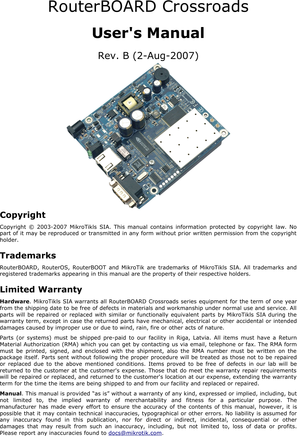
Mikrotikls SIA CRD BROADBAND WIRELESS DATA TRANSMITTER User Manual USERS MANUAL
Mikrotikls SIA BROADBAND WIRELESS DATA TRANSMITTER USERS MANUAL
UserManual.wiki
>
Mikrotikls SIA
>
CRD User Manual
USERS MANUAL
Navigation menu
Upload a User Manual
Namespaces
Wiki Guide
HTML
PDF
Info
Views
User Manual
Discussion / Help
Navigation
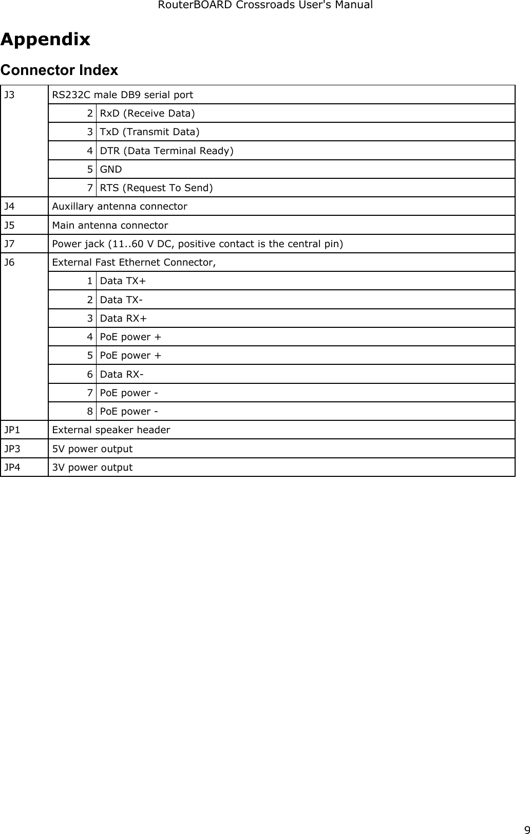
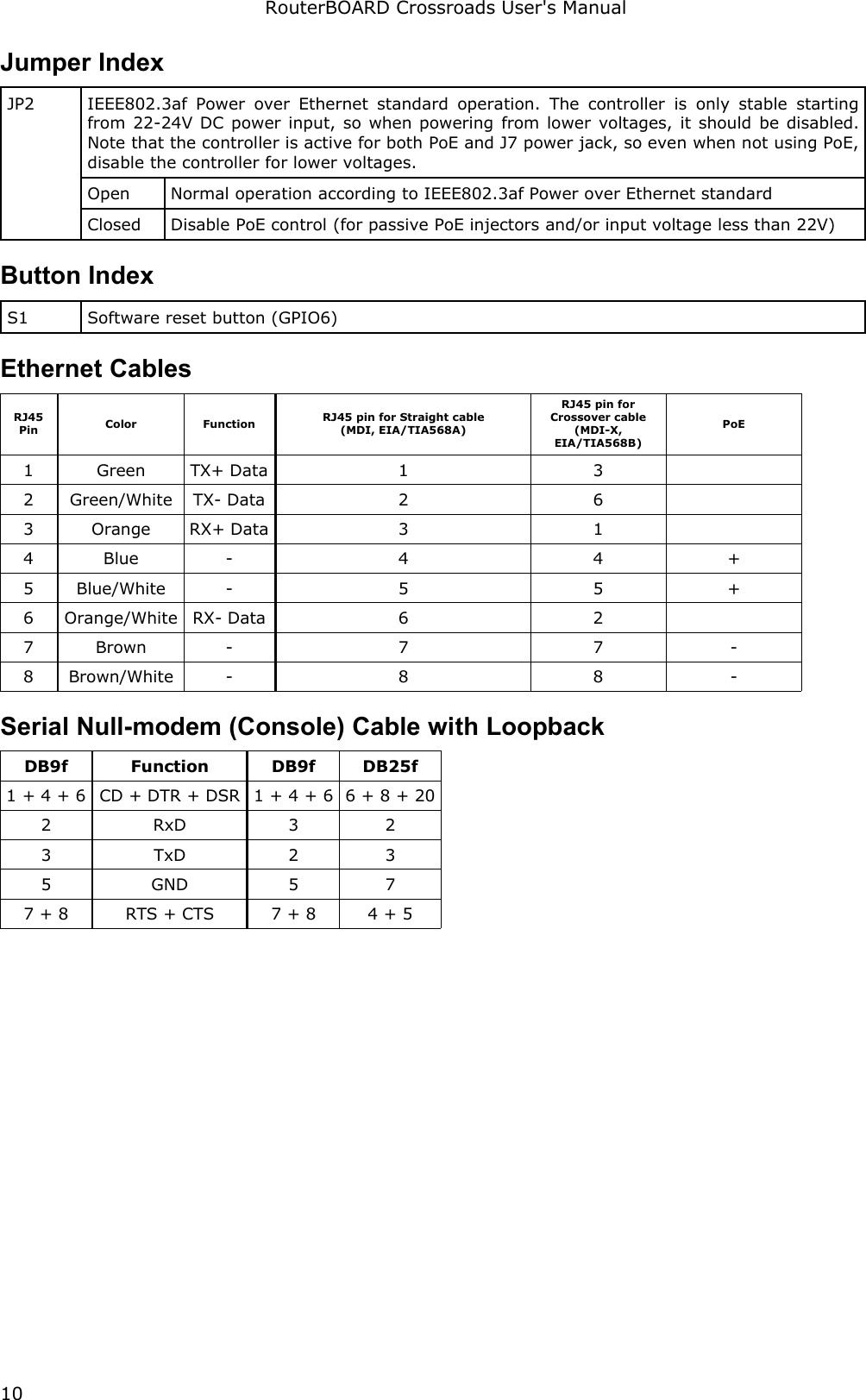
![RouterBOARD Crossroads User's ManualCPU. Crossroads series has MIPS32 little-endian based embedded processor using MIPS 4KEc CPU core. It is fully binary-compatible with all software developed for MIPS32 little-endian (mipsel) instruction set architecture. The MIPS 4KEc core includes TLB Memory Management Unit and does not include Float Point Unit (so it is optimized for integer operations).Ethernet. Crossroads has one onboard Ethernet ports controlled by Atheros AR2316 embedded Fast Ethernet controller.MikroTik RouterOSMikroTik RouterOS, starting from version 2.9.38 (RouterBOARD 100/500 edition) Crossroads series embedded boards.RouterBOOTThe RouterBOOT firmware (also referred as “boot loader” here) provides minimal functionality to boot an Operating System. It supports serial console via the onboard serial port at the boot time. The loader supports booting from the onboard NAND device and from a network server (see the respective section for details on this protocol). Supported OSs:●MikroTik RouterOS starting with version 2.9.38Boot Loader ConfigurationLoader parameters may be configured through the onboard RS232C DB9 asynchronous serial interface. To connect to it, use a standard null-modem cable. By default, the port is set to 115200bit/s, 8 data bits, 1 stop bit, no parity. Note that the device does not fully implement the hardware (RTS/CTS) flow control, so it is suggested to try to disable hardware flow control in the terminal emulation program in case the serial console does not work as expected, and if it does not help, make a new cable using the pinout given in the Appendix.To enter the loader configuration screen, press any key (or only [Delete] key (or [Backspace] key – see the note for the respective configurable option), depending on the actual configuration) just after the loader is asking for it:RouterBOOT booter 1.5RouterBoard CrossroadsCPU frequency: 184 MHz Memory size: 32 MBPress any key within 5 seconds to enter setupRouterBOOT-1.5What do you want to configure? d - boot delay k - boot key s - serial console o - boot device u - cpu mode r - reset configuration g - upgrade firmware i - board info p - boot protocol t - do memory testing x - exit setupyour choice:To select a menu point, press the key written at the beginning of this line. Pressing [Enter] selects the option marked with '*'.Configurable Optionsboot delay – how much time to wait for a key stroke while booting (1..9 seconds; 2 second by default).boot key – which key will cause the loader to enter configuration mode during boot delay (any key | <Delete> key only; any key by default). Note that in some serial terminal programs, it is impossible to use 7](https://usermanual.wiki/Mikrotikls-SIA/CRD/User-Guide-829433-Page-7.png)
![RouterBOARD Crossroads User's Manualthe [Delete] key to enter the setup – in this case it might be possible to do this with the [Backspace] key.serial console – to configure initial serial console bitrate (1200 | 2400 | 4800 | 9600 | 19200 | 38400 | 57600 | 115200; 115200 bps by default).boot device – initial boot device (boot over Ethernet | boot from NAND | boot Ethernet once, then NAND; boot from NAND by default). You can also select boot chosen device option to boot from the device selected immediately, without saving the setting.cpu mode – whether to enter CPU suspend mode on WAIT instruction (power save | regular; power save by default). Most OSs use WAIT instruction during CPU idle cycle. When CPU is in suspend mode, it consumes less power, but in low-temperature conditions (below 0°C) it is recommended to choose regular mode, so that overall system temperature would be higher.reset configuration – whether to reset all the boot loader settings to their respective default values (yes | no; no by default).upgrade firmware – receive a new boot loader image using XModem protocol over serial line or using DHCP/BOOTP and TFTP protocols through the Ethernet network (upgrade firmware over ethernet | upgrade firmware over serial port).board info – prints the serial number, boot loader version, CPU frequency, memory size and MAC addresses of the onboard Ethernet portsboot protocol – network booting protocol (bootp protocol | dhcp protocol; bootp protocol by default).do memory testing – performs a full memory test.Boot Loader UpgradingThe boot loader is needed to initialize all the hardware and boot the system up. Newer loader versions might have support for more hardware, so it's generally a good idea to upgrade the loader once a newer version is available. You can upgrade the loader through the onboard serial port using XModem protocol (programs available for all major OSs). For example, you can use HyperTerminal for Windows or Minicom for Linux to upload the boot loader. Alternatively if you have a DHCP/BOOTP and TFTP servers available, you can specify the loader image as a boot image and choose the bios upgrade over ethernet option in the boot loader configuration menu. The loader will get the image from the TFTP server and upgrade itself. The most current loader image is available for download on www.routerboard.com.If you are using a Microsoft Windows series operating system, you can use the remote upgrading application available on www.routerboard.com. This program boots the RouterBOARD from network and upgrades the loader. Note that the upgrade may only take place within the same broadcast domain (i.e. there must not be any routers between the Windows-based machine and the upgradable RouterBOARD).The boot loader upgrading is supported also from MikroTik RouterOS. The procedure is described in the MikroTik RouterOS manual.8](https://usermanual.wiki/Mikrotikls-SIA/CRD/User-Guide-829433-Page-8.png)