Mikrotikls SIA QRTG2SHPND DIGITAL TRANSMISSION SYSTEM User Manual
Mikrotikls SIA DIGITAL TRANSMISSION SYSTEM
User Manual
Seewww.routerboard.com formore information. Contactsupport@mikrotik.com forsupportquestions. 21/08/13
RouterBOARD QRTG2SHPnD
Quick Setup Guide and Warranty Information
The RouterBOARD QRT comes as acomplete kit. Itincludes abuilt
in802.11b/g/n dual chain wireless device, and adual polarization
17dBi antenna. Ithas one Gigabit Ethernetconnector which
supports MDIXauto detection.
First use
1. Connect anEthernet cable tothe port behind
the small plastic door
2. The QRT accepts 24V PassivePoEfrom aPoEinjector
3. The default IPaddress from LAN is 192.168.88.1for
configuration from a web browser
4. Username is admin and thereis no password
Powering
The device accepts powering from the Ethernetport(Passive PoE) 830V DC. Package contains a24V
adapter. Maximum power consumption of the device is 21W @24V. s
Bootingprocess
Initial connection has to be done viathe Ethernetcable. Open 192.168.88.1inyourwebbrowser.
Username is admin and there is no password. In case IP connection is notavailable, Winbox can be used
to connectto the MAC address of the device. More information here:
http://wiki.mikrotik.com/wiki/First_time_startup
In case you wish to bootthe device from network, for example to use MikroTik Netinstall, hold the
RESET button of the device when starting ituntil
the LED lightturns off, and Metal will startto look
for Netinstall servers.
Mounting
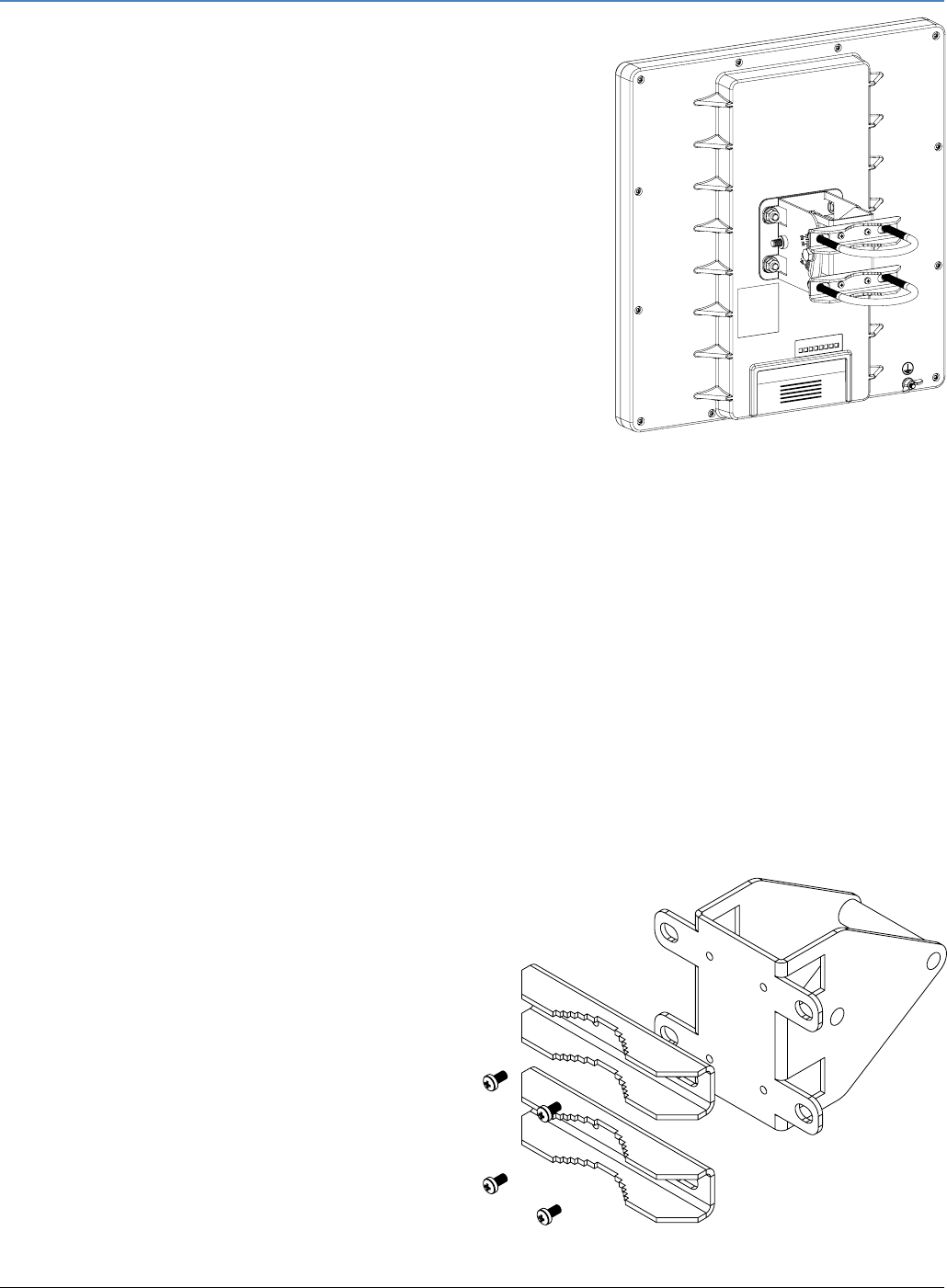
The QRT box contains several parts thatneed to be
assembled. Please follow this process:
Start by attaching thetwo polebrackets (A) to the
swivel adjuster (B), by using thefour provided screws
(use a PH1 screwdriver).
A
B
Seewww.routerboard.com formore information. Contactsupport@mikrotik.com forsupportquestions. 21/08/13
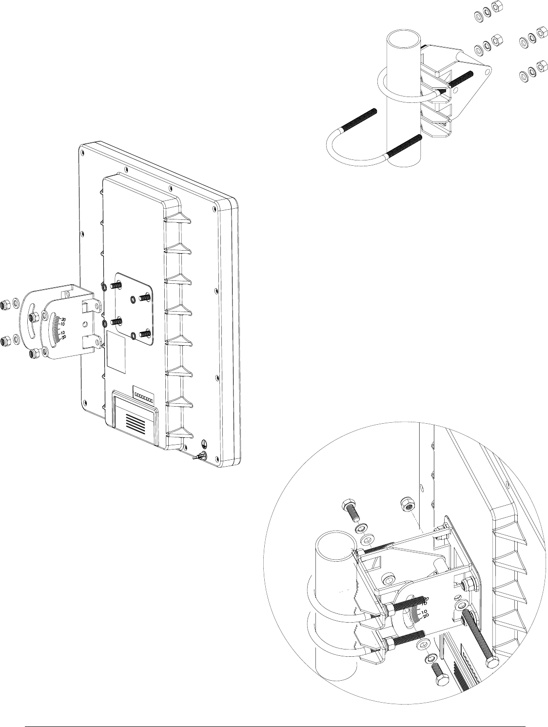
Next,put the twoUbolts (C) aroundthe mast or pole, andguide
them through the holes on the swivel adjuster (D).Then, tighten
the Ubolts, eachwithone regular washer, one spring washer, and
one nut,asshownintheimagetothe right. All nuts needtobe
tightened using a size 10 (3/8 in)wrench.
Now take the mounting bracket (E), and put it on to the
back of the antenna. Use one rubber ring, one washer, and
one nut foreach of the builtin bolts (in that order).
Finally, attach theswivel adjuster to themounting
bracket. Use the long bolt intheposition (F). Put
one regular washer, andone spring washer ontothe
shorter screws, then put them in positions(G). Do
not tightentoomuch, as youneedtoadjust the
antennanow.
Once antenna level and angle are adjusted
according to thewireless signal in software, tighten
all nuts.Note the degrees of angle forfuture
reference.
C
D
F
E
G
G

Seewww.routerboard.com formore information. Contactsupport@mikrotik.com forsupportquestions. 21/08/13
Buttons and Jumpers
�RouterOS reset jumper hole (access throughthe plastic door) – resets RouterOS software to defaults.
Must short circuit the metallic sides of the hole (with a screwdriver, for example) and boot the device.
Hold screwdriver in place until RouterOS configuration is cleared.
�RouterBOOT reset button(access throughthe plastic door)has two functions:
Hold this button during boot time until LEDlight starts flashing,
release the button to reset RouterOS configuration (same resultas with resethole)
Hold this button during boot time longer, until LEDturns off,
and then releaseit to makethedevicelookforNetinstallservers.
Operating System Support
Currently tested operating system is MikroTik RouterOS (starting from version v5.20).
Copyright and Warranty Information
Copyright and Trademarks. CopyrightMikroTikls SIA. This manual contains information protected by
copyrightlaw. No partof itmay be reproduced or transmitted in any form withoutprior written
permission from the copyrightholder. RouterBOARD, RouterOS, RouterBOOT and MikroTik are
trademarks of MikroTikls SIA. All trademarks and registered trademarks appearing in this manual are the
property of their respective holders.
Hardware. MikroTikls SIA warrants all RouterBOARD series equipmentfor the term of fifteen (15)
months from the shipping date to be free of defects in materials and workmanship under normal use
and service, exceptin case of damage caused by mechanical, electrical or other accidental or intended
damages caused by improper use or due to wind, rain, fire or other acts of nature.
If you have purchased your productfrom aMikroTik Reseller, please contactthe Reseller company
regarding all warranty and repair issues, the following instructions apply ONLY if you purchased your
equipmentdirectly from MikroTik Latvia
To return failed unitor units to MikroTikls you mustperform the following RMA (Return Material
Authorization) procedure. Follow the instructions below to save time, efforts, avoid costs, and improve
the speed of the RMA process.
Instructions are located on our webpage here: http://rma.mikrotik.com
Manual. This manual is provided “as is” withoutawarranty of any kind, expressed or implied,including,
butnotlimited to, the implied warranty of merchantability and fitness for aparticular purpose. The
manufacturer has made every effortto ensure the accuracy of the contents of this manual; however, it
is possible thatitmay contain technical inaccuracies, typographical or other errors. No liability is
assumed for any inaccuracy found in this publication, nor for director indirect, incidental, consequential
or other damages thatmay resultfrom such an inaccuracy, including, butnot limited to, loss of dataor
profits. Please reportany inaccuracies found to support@mikrotik.com

Federal Communication Commission Interference Statement
(FCC ID: TV7QRTG2SHPND)
This equipment has been tested and found to comply with the limits for
a Class B digital device, pursuant to Part 15 of the FCC Rules. These
limits are designed to provide reasonable protection against harmful interference in
a residential installation.
This equipment generates, uses and can radiate radio frequency energy and, if not
installed and used in accordance with the instructions, may cause harmful
interference to radio communications. However, there is no guarantee that
interference will not occur in a particular installation. If this equipment does cause
harmful interference to radio or television reception, which can be determined by
turning the equipment off and on, the user is encouraged to try to correct the
interference by one of the following measures:
•Reorient or relocate the receiving antenna.
•Increase the separation between the equipment and receiver.
•Connect the equipment into an outlet on a circuit different from that to which
the receiver is connected.
•Consult the dealer or an experienced radio/TV technician for help.
FCC Caution: Any changes or modifications not expressly approved by the party
responsible for compliance could void the user’s authority to operate this
equipment.
This device complies with Part 15 of the FCC Rules. Operation is subject to the
following two conditions: (1) This device may not cause harmful interference, and
(2) this device must accept any interference received, including interference that
may cause undesired operation.
This device and its antenna must not be co-located or operation in conjunction with
any other antenna or transmitter.
IMPORTANT: Exposure to Radio Frequency Radiation.
28 cm minimum distance has to be maintained between the antenna and user.
Under such configuration, the FCC radiation exposure limits set forth for an
population/uncontrolled environment can be satisfied.
See www.routerboard.com for more information. Contact support@mikrotik.com for support questions. 12/02/14