Mikrotikls SIA R52HN WLAN 802.11a/b/g/n MiniPCI module User Manual
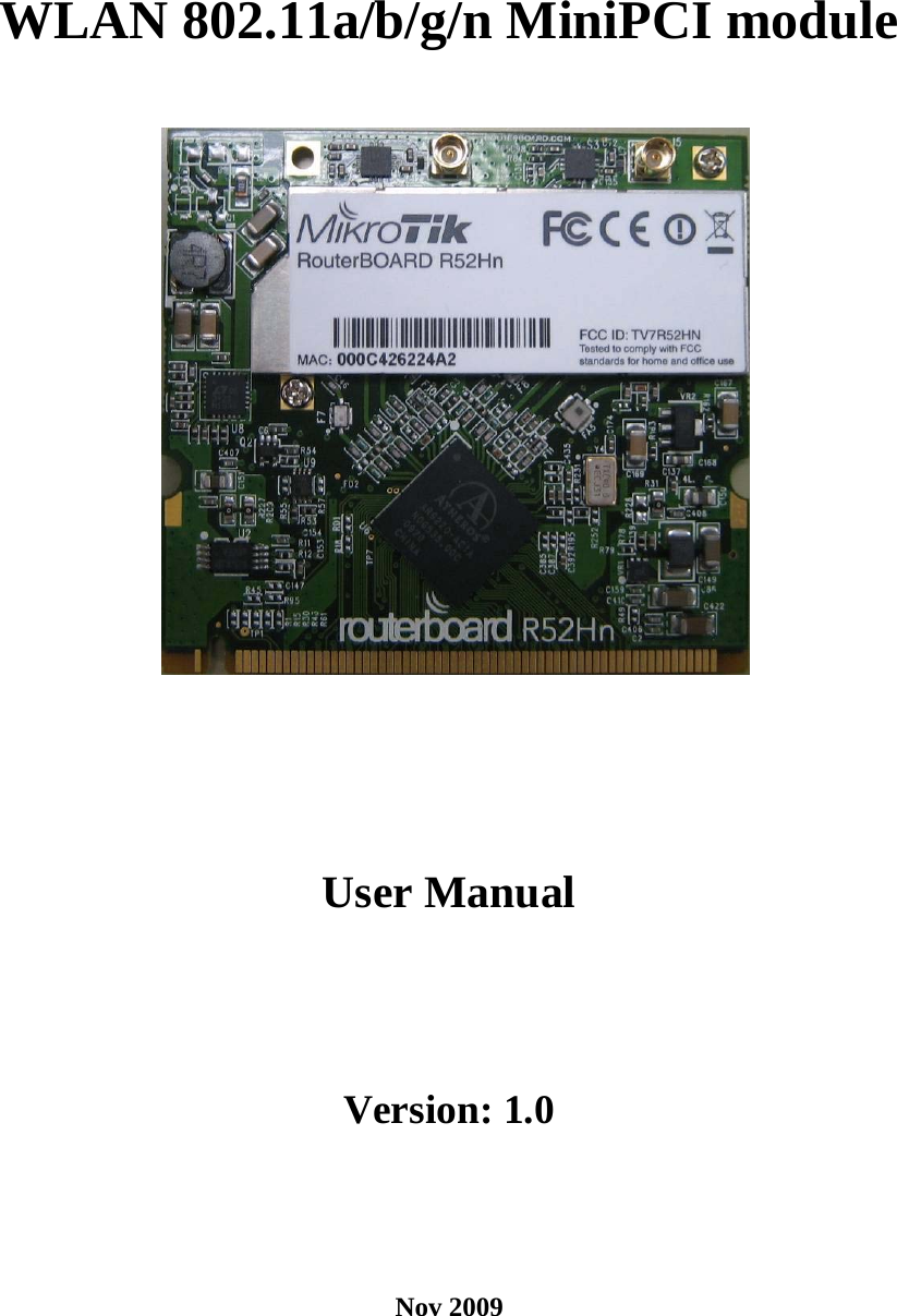
Mikrotikls SIA WLAN 802.11a/b/g/n MiniPCI module
UserManual.wiki
>
Mikrotikls SIA
>
R52HN User Manual
User Manual
Navigation menu
Upload a User Manual
Namespaces
Wiki Guide
HTML
PDF
Info
Views
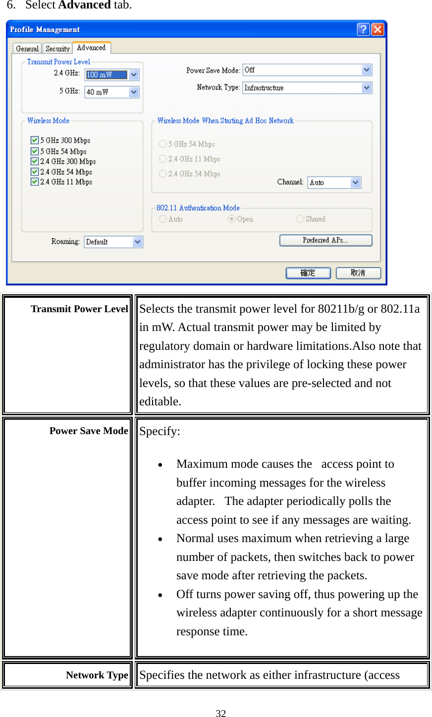
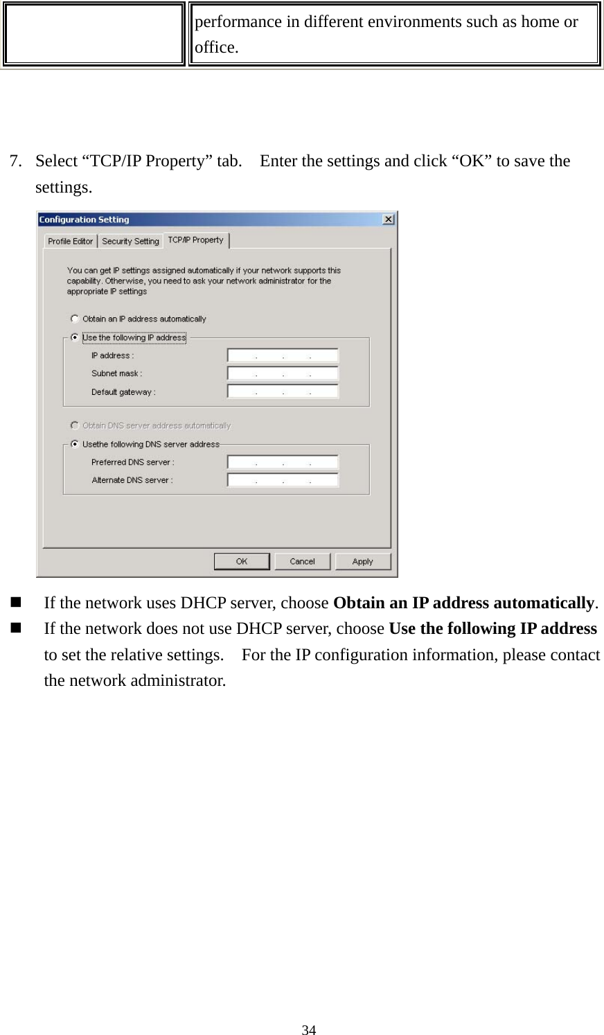
User Manual
Discussion / Help
Navigation