Mikrotikls SIA RB411AR DIGITAL TRANSMISSION SYSTEM OPERATING 802.11B/G MODES User Manual Owners Manual
Mikrotikls SIA DIGITAL TRANSMISSION SYSTEM OPERATING 802.11B/G MODES Owners Manual
UserManual.wiki
>
Mikrotikls SIA
>
RB411AR User Manual
Owners Manual
Navigation menu
Upload a User Manual
Namespaces
Wiki Guide
HTML
PDF
Info
Views
User Manual
Discussion / Help
Navigation
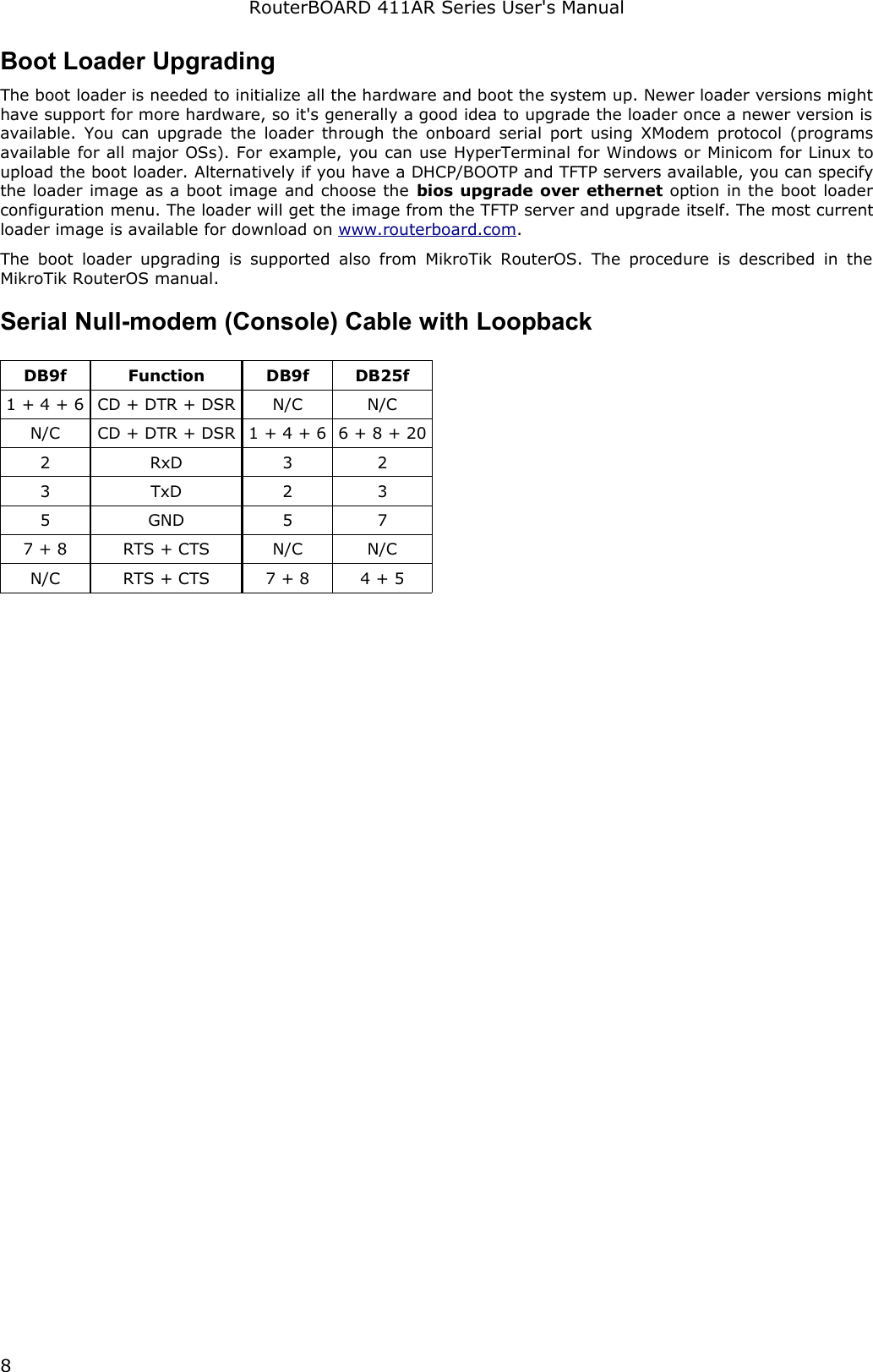
![RouterBOARD 411AR Series User's ManualBoot Loader ConfigurationLoader parameters may be configured through the onboard RS232C DB9 asynchronous serial interface. To connect to it, use a standard null-modem cable. By default, the port is set to 115200bit/s, 8 data bits, 1 stop bit, no parity. Note that the device does not fully implement the hardware (RTS/CTS) flow control, so it is suggested to try to disable hardware flow control in the terminal emulation program in case the serial console does not work as expected, and if it does not help, make a new cable using the pinout given in the Appendix.To enter the loader configuration screen, press any key (or only [Delete] key (or [Backspace] key – see the note for the respective configurable option), depending on the actual configuration) just after the loader is asking for it:RouterBOOT booter 2.12RouterBoard 411CPU frequency: 300 MHz Memory size: 32 MBPress any key within 2 seconds to enter setupRouterBOOT-2.12What do you want to configure? d - boot delay k - boot key s - serial console o - boot device u - cpu mode r - reset configuration e - format nand g - upgrade firmware i - board info p - boot protocol t - do memory testing x - exit setupyour choice:To select a menu point, press the indicated key. Pressing [Enter] selects the option marked with '*'.Configurable Optionsboot delay – how much time to wait for a key stroke while booting (1..9 seconds; 2 second by default).boot key – which key will cause the loader to enter configuration mode during boot delay (any key | <Delete> key only; any key by default). Note that in some serial terminal programs, it is impossible to use the [Delete] key to enter the setup – in this case it might be possible to do this with the [Backspace] key.serial console – to configure initial serial console bitrate (1200 | 2400 | 4800 | 9600 | 19200 | 38400 | 57600 | 115200; 115200 bps by default).boot device – initial boot device (boot over Ethernet | boot from NAND | boot Ethernet once, then NAND; boot from NAND by default). You can also select boot chosen device option to boot from the device selected immediately, without saving the setting.cpu mode – whether to enter CPU suspend mode on WAIT instruction (power save | regular; power save by default). Most OSs use WAIT instruction during CPU idle cycle. When CPU is in suspend mode, it consumes less power, but in low-temperature conditions (below 0°C) it is recommended to choose regular mode, so that overall system temperature would be higher.reset configuration – whether to reset all the boot loader settings to their respective default values (yes | no; no by default).format nand – perform a low-level NAND format. During this operation, all previously marked bad sectors are retested to find out if they are faulty indeed.upgrade firmware – receive a new boot loader image using XModem protocol over serial line or using DHCP/BOOTP and TFTP protocols through the Ethernet network (upgrade firmware over ethernet | upgrade firmware over serial port).board info – prints the serial number, boot loader version, CPU frequency, memory size and MAC addresses of the onboard Ethernet portsboot protocol – network booting protocol (bootp protocol | dhcp protocol; bootp protocol by default).do memory testing – performs a full memory test.7](https://usermanual.wiki/Mikrotikls-SIA/RB411AR/User-Guide-1132399-Page-8.png)