Mikrotikls SIA SXTG-5HPND Digital Transmission System User Manual
Mikrotikls SIA Digital Transmission System
User Manual
RB SXT G5HPnDHG
Quick Setup Guide and Warranty Information
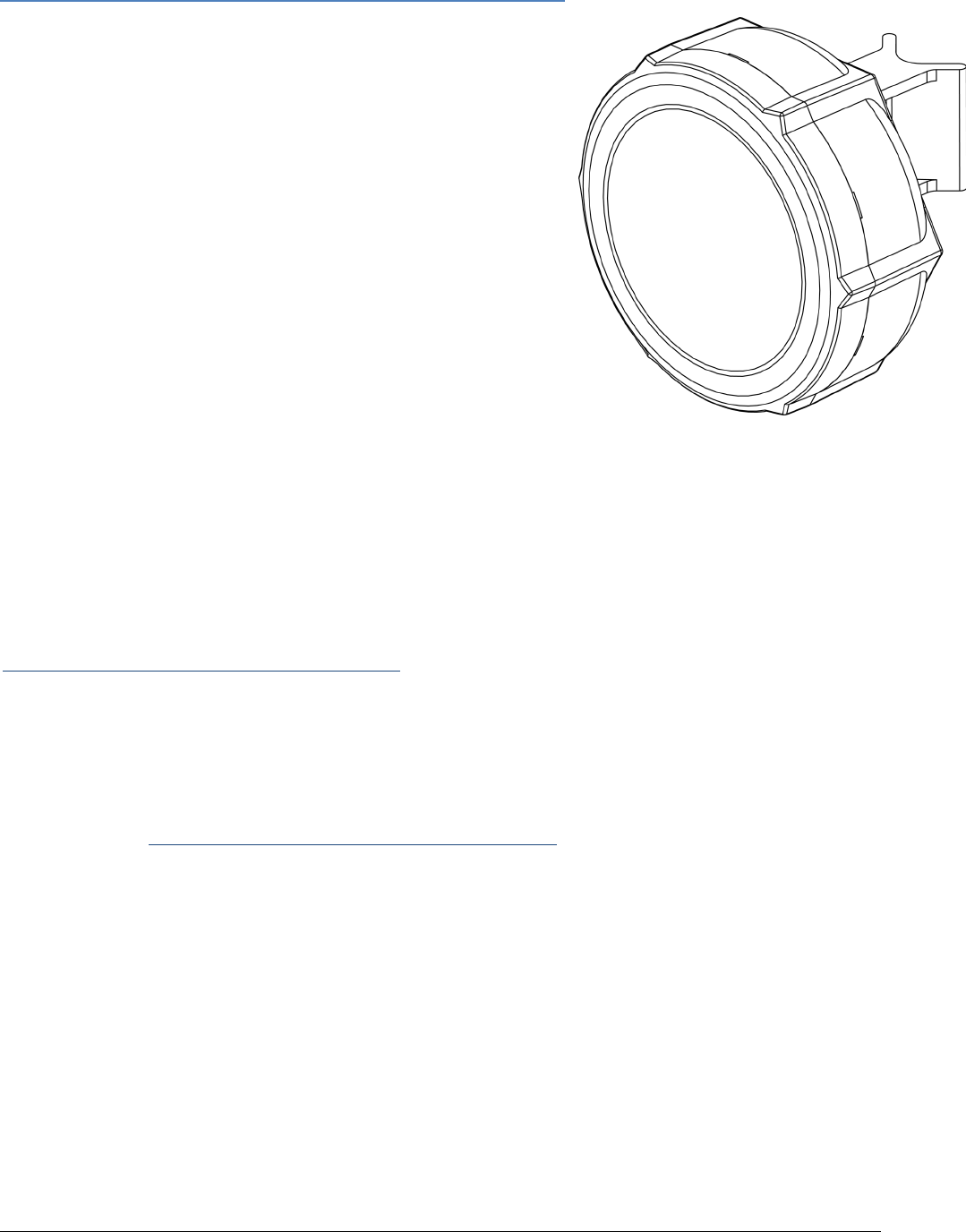
The SXTG5HPnDHG comesasa complete set, and includesabuiltin
802.11n dual chain wireless device, and adual polarization16dBi high
gain antenna. It has one Gigabit Ethernet connector which supports
MDIXautodetection.
First use
1. Connectan Ethernetcable to the portbehind
the small plastic door
2. The SXT accepts 24V Passive PoE from the
supplied PoE injector
3. The defaultIP address from LAN is 192.168.88.1
for configuration
4. Username isadmin and there is no password
Powering
The board accepts powering from the Ethernet port (Passive PoE) 830V DC. Packagecontains a24V adapter.
Booting process
RouterOS is the operating system of all RouterBOARD routers. Please see detailed configuration guide here:
http://wiki.mikrotik.com/wiki/Category:Manual
This device doesn't come fitted with aSerial Port connector, so initial connection has to be done viathe Ethernet
cable, using the MikroTikWinboxutility. Winboxshould be used to connect to the default IP addressof
192.168.88.1with the username admin and no password.
IncaseIPconnectionisnotavailable,WinboxcanalsobeusedtoconnecttotheMACaddressofthedevice.More
informationhere: http://wiki.mikrotik.com/wiki/First_time_startup
Incaseyouwishtobootthedevicefromnetwork,forexampletouseMikroTikNetinstall,holdtheRESETbutton
of the device whenstarting it until the LED LD600 light turns off (behindthe small door), andSXT will start tolook
forNetinstall servers.
Mounting
With the clip pointed forward, slide the mounting bracket into the rail on the bottom of the case, until the clip
clicksinto place. The SXT comesbundled with a hose clamp guidetheclamp through theopeningin thebracket
and around thepolewhereit will bemounted. Tighten thehoseclamp screw when alignment is complete. Two
screw holesare provided asadditional security against accidental bracket movement.
The SXTdevice has asliding door, behind which the Ethernet port and thereset jumpers arelocated. This door
can be also secured shut with a screw in the provided screw hole.

Buttons and Jumpers
�RouterOS resetjumper hole (access through the plastic door) – resets RouterOS software to de
faults. Mustshortcircuitthe metallic sides of the hole (with ascrewdriver, for example) and boot
the device. Hold screwdriver in place until RouterOS configuration is cleared.
�RouterBOOT resetbutton (access through the plastic door) has two functions:
Hold this button during boottime until LED lightstarts flashing,
release the button to reset RouterOS configuration (same resultas with resethole)
Hold this button during boottime longer, until LED turns off,
and then release itto make the device lookfor Netinstall servers.
Operating System Support
Currently testedoperating system is MikroTik RouterOS (starting from versionv5).
Copyright andWarranty Information
Copyright and Trademarks. Copyright MikroTikls SIA. This manual contains informationprotectedby copyright
law.Nopartofitmaybereproducedortransmittedinanyformwithoutpriorwrittenpermissionfromthecopy
rightholder. RouterBOARD, RouterOS, RouterBOOT and MikroTik aretrademarks of MikroTikls SIA. All trademarks
and registered trademarks appearing in this manual aretheproperty of their respectiveholders.
Hardware.MikroTikls SIA warrants allRouterBOARD series equipment for the term of fifteen (15) months from
the shipping date to be free of defectsin materialsand workmanship under normal use and service, except in
case of damage caused bymechanical, electrical or other accidental or intended damagescaused byimproper use
or due towind, rain, fire or other acts of nature.
IfyouhavepurchasedyourproductfromaMikroTikReseller,pleasecontacttheResellercompanyregardingall
warranty and repair issues, the following instructions apply ONLY ifyoupurchasedyourequipmentdirectlyfrom
MikroTik Latvia
To return failed unitorunits to MikroTikls you mustperform the following RMA (Return Material Authorization)
procedure. Follow the instructions below tosave time, efforts, avoidcosts, andimprove the speedof the RMA
process. Take intoaccount that all goods have one year warranty.
Instructionsarelocatedonourwebpagehere:http://rma.mikrotik.com
Manual. This manual is provided “as is” without a warranty of any kind, expressed or implied, including, but not
limitedto,theimpliedwarrantyofmerchantabilityandfitnessforaparticularpurpose.Themanufacturerhas
made every effort to ensure the accuracy of the contents of this manual; however, it is possible that it may con
tain technical inaccuracies, typographical orothererrors. No liability is assumedfor any inaccuracy foundinthis
publication, nor for direct or indirect, incidental, consequential or other damages that may result from suchan
inaccuracy,including,butnotlimitedto,lossofdataorprofits.Pleasereportanyinaccuraciesfound to sup
port@mikrotik.com

Federal Communication Commission Interference Statement
(FCC ID: TV7SXTG-5HPND)
This equipment has been tested and found to comply with the limits for a Class B
digital device, pursuant to Part 15 of the FCC Rules. These limits are designed to
provide reasonable protection against harmful interference in a residential
installation.
This equipment generates, uses and can radiate radio frequency energy and, if not installed
and used in accordance with the instructions, may cause harmful interference to radio
communications. However, there is no guarantee that interference will not occur in a particular
installation. If this equipment does cause harmful interference to radio or television reception,
which can be determined by turning the equipment off and on, the user is encouraged to try to
correct the interference by one of the following measures:
•Reorient or relocate the receiving antenna.
•Increase the separation between the equipment and receiver.
•Connect the equipment into an outlet on a circuit different from that to which the
receiver is connected.
•Consult the dealer or an experienced radio/TV technician for help.
FCC Caution: Any changes or modifications not expressly approved by the party responsible
for compliance could void the user’s authority to operate this equipment.
This device complies with Part 15 of the FCC Rules. Operation is subject to the following two
conditions: (1) This device may not cause harmful interference, and (2) this device must
accept any interference received, including interference that may cause undesired operation.
This device and its antenna must not be co-located or operation in conjunction with any other
antenna or transmitter.
IMPORTANT: Exposure to Radio Frequency Radiation.
27 cm minimum distance has to be maintained between the antenna and the occupational user
and 60 cm to general public. Under such configuration, the FCC radiation exposure limits set
forth for an population/uncontrolled environment can be satisfied.
Antenna Installation. WARNING: It is installer's responsibility to ensure that when using
the authorized antennas in the United States (or where FCC rules apply); only those antennas
certified with the product are used. The use of any antenna other than those certified with the
product is expressly forbidden in accordance to FCC rules CFR47 part 15.204. The installer
should configure the output power level of antennas, according to country regulations and per
antenna type. Professional installation is required of equipment with connectors to ensure
compliance with health and safety issues.