MilDef Crete DK886EX TABLET COMPUTER User Manual DK886 User Guide 080522
MilDef Crete Inc. TABLET COMPUTER DK886 User Guide 080522
UserManual.wiki
>
MilDef Crete
>
DK886EX User Manual
user manual
Navigation menu
Upload a User Manual
Namespaces
Wiki Guide
HTML
PDF
Info
Views
User Manual
Discussion / Help
Navigation
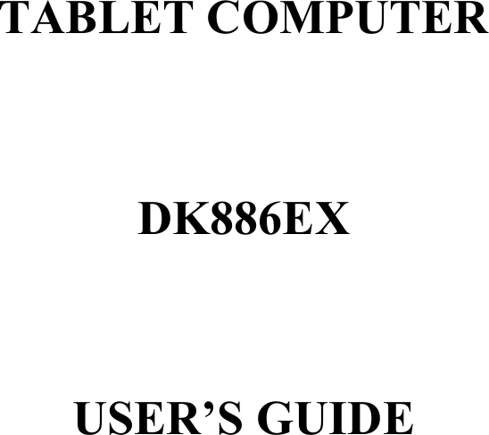

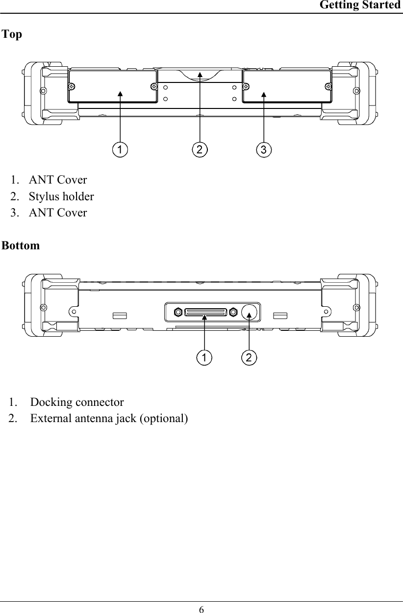
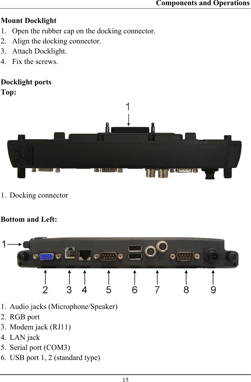
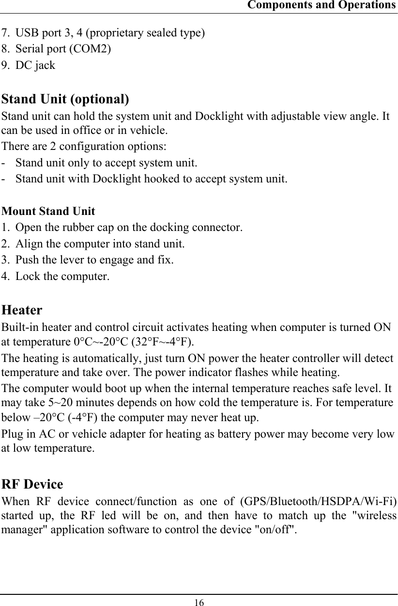
![Components and Operations 14 External Backlight Keyboard (optional) The external backlight keyboard is equivalent to a full size desktop keyboard plus extra functions. The interface is via USB port. Track point The track point is functionally equivalent to a mouse. Pushing the track point may move the cursor on the screen. The 2 buttons act same as mouse buttons. Backlight Press [I-O] key for approximately 1 second turns keyboard backlight ON or OFF. Docklight (optional) Docklight acts as docking unit or port enhancer. It contains more ports that are not available on system unit.](https://usermanual.wiki/MilDef-Crete/DK886EX/User-Guide-1199043-Page-22.png)
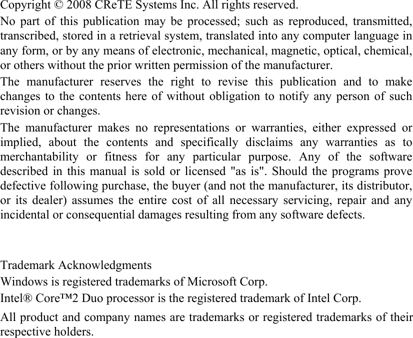
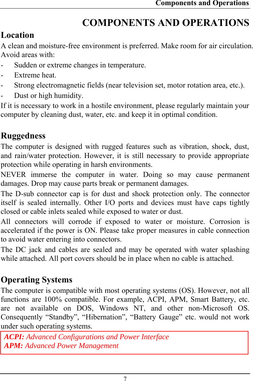
![BIOS Setup 24 BIOS SETUP Press [F2] at boot up to enter BIOS setup. Use arrow keys to select options and [+/-] to modify them. When finished, move to” Exit” and press [Enter] then confirm save by pressing [Y]. Main Menu Phoenix TrustedCore (tm) Setup Utility Main Advanced Security TPM State Boot Exit Item Specific Help System Time: [16:19:20] System Date: [03/02/2007] Legacy Diskette A: [1.44/1.25MB 3½"] • IDE Channel 0 Master [None] • IDE Channel 0 Slave [None] • IDE Channel 1 Master [None] • IDE Channel 1 Slave [None] System Memory: 640 KB Extended Memory: 1038336 KB <Tab>, <Shift-Tab>, or <Enter> selects field. F1 Help ↑↓ Select Item –/+ Change Values F9 Setup Defaults Esc Exit ↔ Menu Enter Select ► Sub-Menu F10 Save and Exit Note: The contents may vary depending on computer configurations. Main Menu Selections You can make the following selections on the Main Menu. Use the sub-menus for other selections. Feature Options Description System Time HH:MM:SS Set the system time Hour, Minute, Second. System Date MM/DD/YYYY Set the system date Month, Day, Year. Legacy Diskette A Disabled 360 Kb 5¼" 1.2 MB 5¼" 720 Kb 3½" 1.44/1.25 MB 3½" 2.88 MB 3½" Select floppy type. Note that 1.25 MB 3½” references a 1024 byte/sector Japanese media format. The 1.25MB, 3½" diskette requires a 3-Mode floppy-disk drive.](https://usermanual.wiki/MilDef-Crete/DK886EX/User-Guide-1199043-Page-32.png)
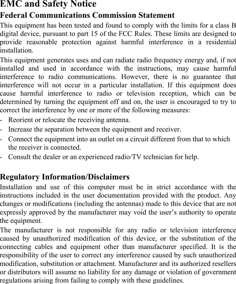
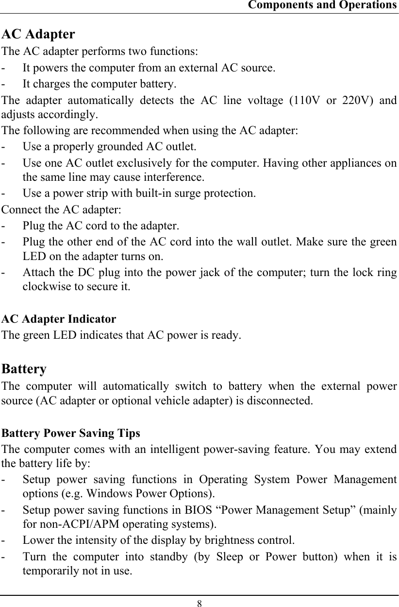
![BIOS Setup 25 IDE Channel 0 Master Sub-Menu Phoenix TrustedCore (tm) Setup Utility Main IDE Channel 0 Master [None] Item Specific Help Type: [Auto] Multi-Sector Transfers: [Disabled] LBA Mode Control: [Disabled] 32 Bit I/O: [Disabled] Transfer Mode: [Standard] Ultra DMA Mode: [Disabled] User = you enter parameters of hard-disk drive installed at this connection. Auto = autotypes hard-disk drive installed here. CD-ROM = a CD-ROM drive is installed here. ATAPI Removable = removable disk drive is installed here. F1 Help ↑↓ Select Item –/+ Change Values F9 Setup Defaults Esc Exit ↔ Menu Enter Select ► Sub-Menu F10 Save and Exit IDE Channel 0 Master Sub-Menu Selections You can make the following selections on the IDE Channel 0 Master sub-menu. Feature Options Description Type Auto None ATAPI Removable CD-ROM IDE Removable Other ATAPI User User = you enter parameters of hard-disk drive installed at this connection. Auto = autotypes hard disk drive installed here. CD-ROM = a CD-ROM drive is installed here. ATAPI Removable = removable disk drive is installed here. 32 Bit I/O Disabled Enabled This setting enables or disables 32 bit IDE data transfers.](https://usermanual.wiki/MilDef-Crete/DK886EX/User-Guide-1199043-Page-33.png)
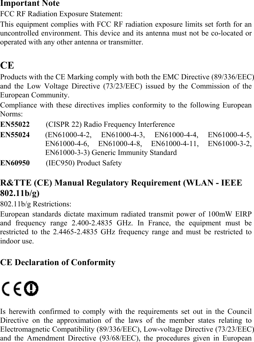
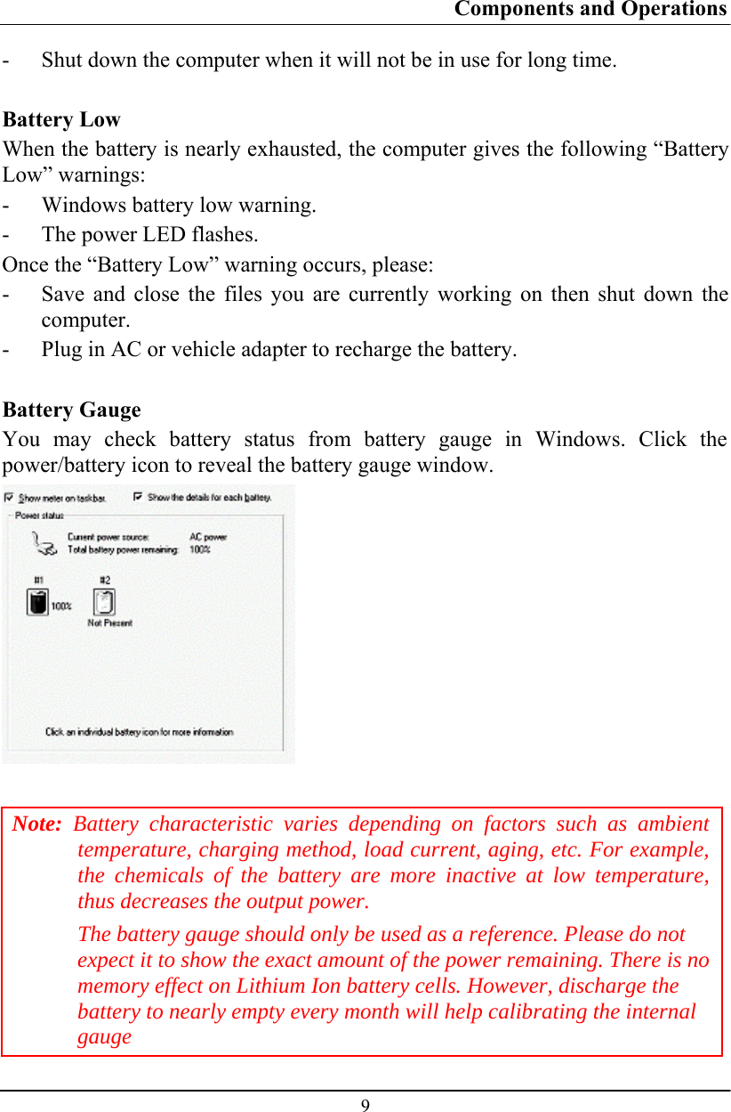
![BIOS Setup 26 IDE Channel 0 Slave Sub-Menu Phoenix TrustedCore (tm) Setup Utility Main IDE Channel 0 Slave [None] Item Specific Help Type: [Auto] Multi-Sector Transfers: [Disabled] LBA Mode Control: [Disabled] 32 Bit I/O: [Disabled] Transfer Mode: [Standard] Ultra DMA Mode: [Disabled] SMART Monitoring: Disabled User = you enter parameters of hard-disk drive installed at this connection. Auto = autotypes hard-disk drive installed here. CD-ROM = a CD-ROM drive is installed here. ATAPI Removable = removable disk drive is installed here. F1 Help ↑↓ Select Item –/+ Change Values F9 Setup Defaults Esc Exit ↔ Menu Enter Select ► Sub-Menu F10 Save and Exit IDE Channel 0 Slave Sub-Menu Selections You can make the following selections on the IDE Channel 0 Slave sub-menu. Feature Options Description Type Auto None ATAPI Removable CD-ROM IDE Removable Other ATAPI User User = you enter parameters of hard-disk drive installed at this connection. Auto = autotypes hard disk drive installed here. CD-ROM = a CD-ROM drive is installed here. ATAPI Removable = removable disk drive is installed here. 32 Bit I/O Disabled Enabled This setting enables or disables 32 bit IDE data transfers.](https://usermanual.wiki/MilDef-Crete/DK886EX/User-Guide-1199043-Page-34.png)
![BIOS Setup 27 IDE Channel 1 Master Sub-Menu Phoenix TrustedCore (tm) Setup Utility Main IDE Channel 1 Master [None] Item Specific Help Type: [Auto] Multi-Sector Transfers: [Disabled] LBA Mode Control: [Disabled] 32 Bit I/O: [Disabled] Transfer Mode: [Standard] Ultra DMA Mode: [Disabled] User = you enter parameters of hard-disk drive installed at this connection. Auto = autotypes hard-disk drive installed here. CD-ROM = a CD-ROM drive is installed here. ATAPI Removable = removable disk drive is installed here. F1 Help ↑↓ Select Item –/+ Change Values F9 Setup Defaults Esc Exit ↔ Menu Enter Select ► Sub-Menu F10 Save and Exit IDE Channel 1 Master Sub-Menu Selections You can make the following selections on the IDE Channel 1 Master sub-menu. Feature Options Description Type Auto None ATAPI Removable CD-ROM IDE Removable Other ATAPI User User = you enter parameters of hard-disk drive installed at this connection. Auto = autotypes hard disk drive installed here. CD-ROM = a CD-ROM drive is installed here. ATAPI Removable = removable disk drive is installed here. 32 Bit I/O Disabled Enabled This setting enables or disables 32 bit IDE data transfers.](https://usermanual.wiki/MilDef-Crete/DK886EX/User-Guide-1199043-Page-35.png)
![BIOS Setup 28 IDE Channel 1 Slave Sub-Menu Phoenix TrustedCore (tm) Setup Utility Main IDE Channel 1 Slave [None] Item Specific Help Type: [Auto] Multi-Sector Transfers: [Disabled] LBA Mode Control: [Disabled] 32 Bit I/O: [Disabled] Transfer Mode: [Standard] Ultra DMA Mode: [Disabled] SMART Monitoring: Disabled User = you enter parameters of hard-disk drive installed at this connection. Auto = autotypes hard-disk drive installed here. CD-ROM = a CD-ROM drive is installed here. ATAPI Removable = removable disk drive is installed here. F1 Help ↑↓ Select Item –/+ Change Values F9 Setup Defaults Esc Exit ↔ Menu Enter Select ► Sub-Menu F10 Save and Exit IDE Channel 1 Slave Sub-Menu Selections You can make the following selections on the IDE Channel 1 Slave sub-menu. Feature Options Description Type Auto None ATAPI Removable CD-ROM IDE Removable Other ATAPI User User = you enter parameters of hard-disk drive installed at this connection. Auto = autotypes hard disk drive installed here. CD-ROM = a CD-ROM drive is installed here. ATAPI Removable = removable disk drive is installed here. 32 Bit I/O Disabled Enabled This setting enables or disables 32 bit IDE data transfers.](https://usermanual.wiki/MilDef-Crete/DK886EX/User-Guide-1199043-Page-36.png)
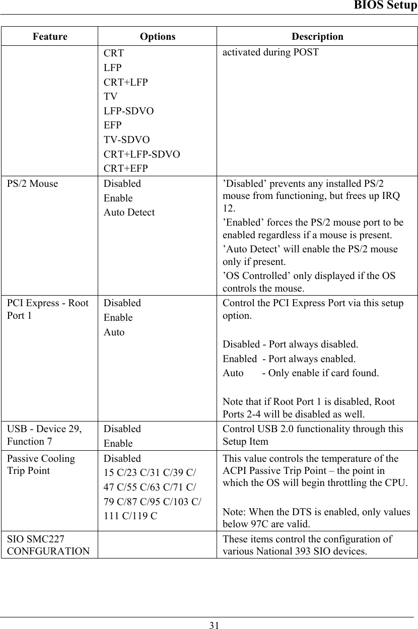
![BIOS Setup 30 Advanced Menu Phoenix TrustedCore (tm) Setup Utility Main Advanced Security TPM State Boot Exit Item Specific Help Legacy USB Support: [Enabled] Summary screen: [Disabled] Boot-time Diagnostic Screen: [Enabled] QuickBoot Mode: [Enabled] Extended Memory Testing [None] IGD - Boot Type: [VBIOS Default] PS/2 Mouse [Auto Detect] PCI Express - Root Port 1: [Enabled] USB - Device 29, Function 7: [Enabled] Passive Cooling Trip Point [79 C] • SIO SMC227 CONFGURATION Enable support for Legacy Universal Serial Bus F1 Help ↑↓ Select Item –/+ Change Values F9 Setup Defaults Esc Exit ↔ Menu Enter Select ► Sub-Menu F10 Save and Exit Warning: Incorrect settings may cause system malfunction. To correct it, restore the Setup Defaults with <F9>. Advanced Menu Selections You can make the following selections on the Advanced Menu. Feature Options Description Legacy USB Support Disabled Enable Enable support for Legacy Universal Serial Bus Summary screen Disabled Enable Display system configuration on boot Boot-time Diagnostic Screen Disabled Enable Display the diagnostic screen during boot QuickBoot Mode Disabled Enable Allows the system to skip certain tests while booting. This will decrease the time needed to boot the system. Extended Memory Testing Normal Just zero it None Determines which type of tests will be performed on extended memory (above 1M).IGD - Boot Type VBIOS Default Select the Video Device that will be](https://usermanual.wiki/MilDef-Crete/DK886EX/User-Guide-1199043-Page-38.png)
![BIOS Setup 32 For most frequently altered setup “SIO SMC227 CONFIDURATION” please refers following: Warning: Incorrect settings in RS485/RS422 of COMx mode may cause SIO component Damage. Must be cautious before Setup. SIO SMC227 Configuration Sub-Menu Phoenix TrustedCore (tm) Setup Utility Advanced SIO SMC227 CONFIGURATION Item Specific Help COM1 port: [3F8-IRQ 4] COM1 mode: [RS232] COM2 port: [2F8-IRQ 3] COM2 mode: [RS232] COM3 port: [3E8-IRQ 10] COM3 mode: [RS232] COM4 port: [2E8-IRQ 5] COM4 mode: [RS232] Printer1: [Disabled] Printer2: [Disabled] Configure COM1 using device options: [Disabled] No configuration [3F8-IRQ 4] Set the base I/O address for COM1 F1 Help ↑↓ Select Item –/+ Change Values F9 Setup Defaults Esc Exit ↔ Menu Enter Select ► Sub-Menu F10 Save and Exit SIO SMC227 Configuration Sub-Menu Selections You can make the following selections on the SIO SMC227 Configuration sub-menu. Feature Options Description COM1 port Disabled 3F8-IRQ 4 Configure COM1 using device options: [Disabled] No configuration [3F8-IRQ 4] Set the base I/O address for COM1 COM1 mode RS232 TTL1 Configure UART mode options: [RS232]:External Device [TTL1]:Internal Device COM2 port Disabled 2F8-IRQ 3 Configure COM2 using device options:](https://usermanual.wiki/MilDef-Crete/DK886EX/User-Guide-1199043-Page-40.png)
![BIOS Setup 33 Feature Options Description [Disabled] No configuration [2F8-IRQ 3] Set the base I/O address for COM2 COM2 mode RS232 TTL2 Configure UART mode options: [RS232]:External Device [TTL2]:Internal Device COM3 port Disabled 3E8-IRQ 10 Configure COM3 using device options: [Disabled] No configuration [3E8-IRQ 10] Set the base I/O address for COM3 COM3 mode RS232 TTL3 Configure UART mode options: [RS232]:External Device [TTL3]:Internal Device COM4 port Disabled 2E8-IRQ 5 Configure COM4 using device options: [Disabled] No configuration [2E8-IRQ 5] Set the base I/O address for COM4 COM4 mode RS232 TTL4 Configure UART mode options: [RS232]:External Device [TTL4]:Internal Device Printer1 Disabled 378-IRQ 4 Configure Printer1 device options: [Disabled] No configuration [378-IRQ 7] Set the base I/O address for Printer1 Printer2 Disabled 3BC Configure Printer2 device options: [Disabled] No configuration [3BC] Set the base I/O address for Printer2](https://usermanual.wiki/MilDef-Crete/DK886EX/User-Guide-1199043-Page-41.png)
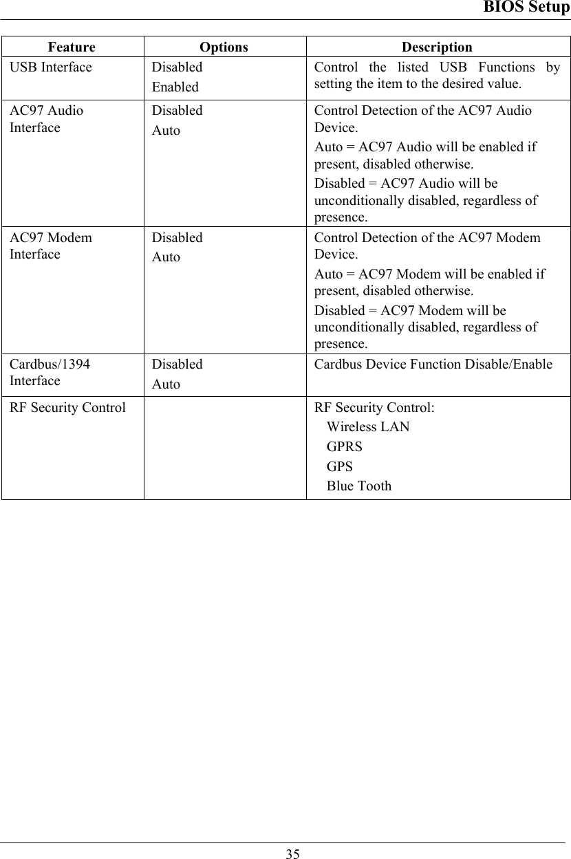
![BIOS Setup 34 Security Menu Warning: If you forget user/supervisor password, the computer has to send back to manufacturer and replace EEPROM to make it work again. Phoenix TrustedCore (tm) Setup Utility Main Advanced Security TPM State Boot Exit Item Specific Help Processor Serial Number [Disabled] Set Supervisor Password [Enter] Set User Password [Enter] Fixed disk boot sector: [Normal] Diskette access: [Supervisor] Password on boot: [Disabled] USB Interface: [Enabled] AC97 Audio Interface: [Auto] AC97 Modem Interface: [Auto] Cardbus/1394 Interface [Auto] • RF Security Control: Controls detection of Processor Serial No. System must be reset or restarted from power-on for settings to take effect.F1 Help ↑↓ Select Item –/+ Change Values F9 Setup Defaults Esc Exit ↔ Menu Enter Select ► Sub-Menu F10 Save and Exit Security Menu Selections You can make the following selections on the Security Menu. Feature Options Description Processor Serial Number Disabled Enabled Controls detection of Processor Serial No. System must be reset or restarted from power-on for settings to take effect. Set Supervisor password Enter New Password Confirm New Password Supervisor Password controls access to the setup utility. Set User Password Enter New Password Confirm New Password User Password controls access to the system at boot. Fixed disk boot sector Normal Write Protect Write protects boot sector on the hard disk to protect against viruses. Diskette access Supervisor Control access to diskette drives Password on boot Disabled Enabled Enables password entry on boot](https://usermanual.wiki/MilDef-Crete/DK886EX/User-Guide-1199043-Page-42.png)
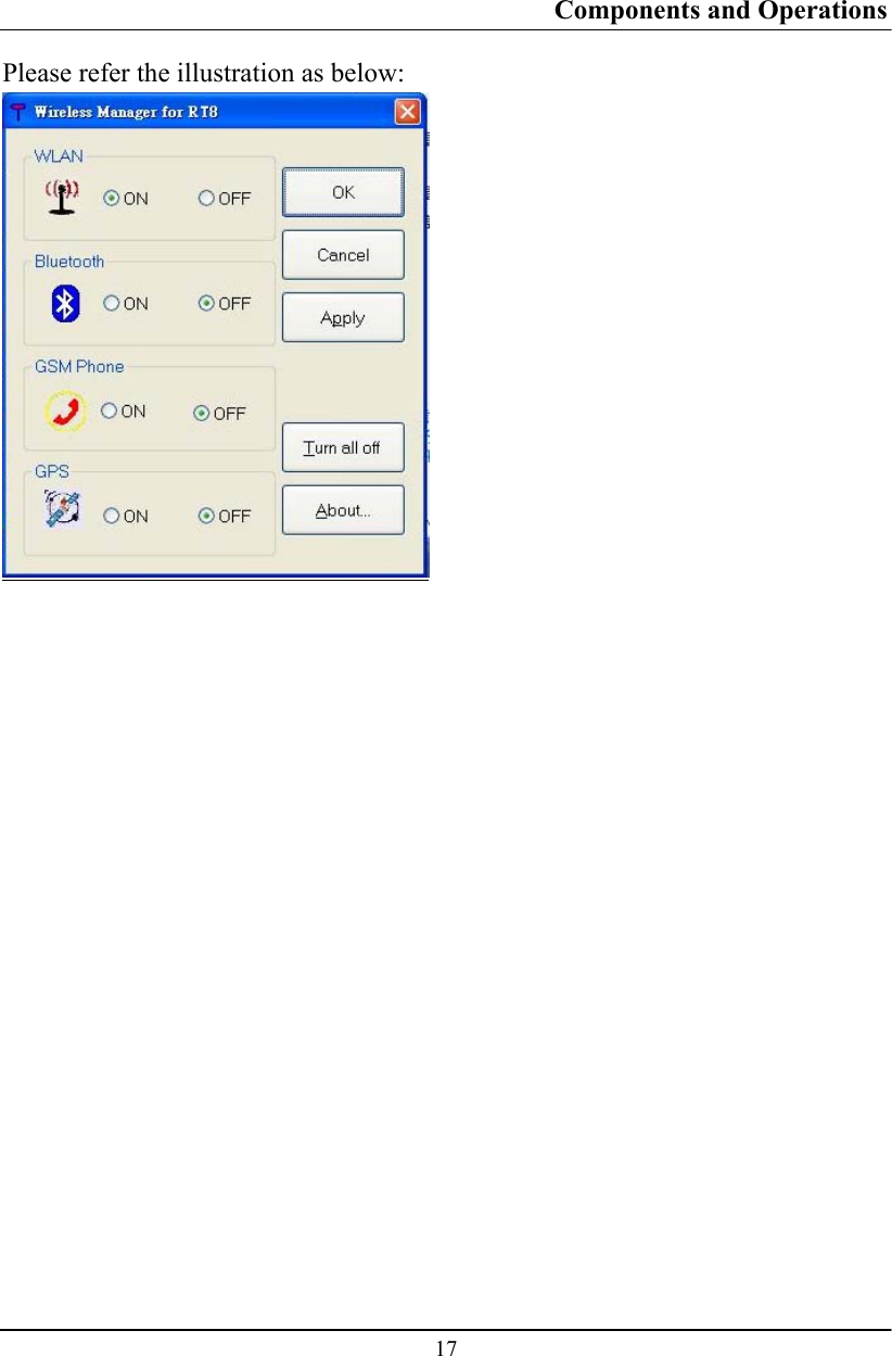
![BIOS Setup 36 For most frequently altered setup “RF Security Control” please refers following: RF Security Control Sub-Menu Phoenix TrustedCore (tm) Setup Utility Security RF Security Control: Item Specific Help Wireless Lan: [Disabled] GPRS: [Disabled] GPS: [Disabled] Blue Tooth: [Disabled] Wireless Lan Control F1 Help ↑↓ Select Item –/+ Change Values F9 Setup Defaults Esc Exit ↔ Menu Enter Select ► Sub-Menu F10 Save and Exit RF Security Control Sub-Menu Selections You can make the following selections on the RF Security Control sub-menu. Feature Options Description Wireless Lan Disabled Enabled Wireless Lan Control Enabled Wireless function GPRS Disabled Enabled GPRS Control Enabled GPRS function GPS Disabled Enabled GPS Control Enabled GPS function Blue Tooth Disabled Enabled Blue Tooth Control Enabled Blue Tooth function](https://usermanual.wiki/MilDef-Crete/DK886EX/User-Guide-1199043-Page-44.png)
![BIOS Setup 37 TPM State Menu Phoenix TrustedCore (tm) Setup Utility Main Advanced Security TPM State Boot Exit Item Specific Help Current TPM State: Enabled and Deactivated Change TPM State: [No Change] Change TPM State F1 Help ↑↓ Select Item –/+ Change Values F9 Setup Defaults Esc Exit ↔ Menu Enter Select ► Sub-Menu F10 Save and Exit TPM State Menu Selections You can make the following selections on the TPM State Menu. Feature Options Description Change TPM State No Change Enable & Activate Deactivate & Disable Clear Change TPM State](https://usermanual.wiki/MilDef-Crete/DK886EX/User-Guide-1199043-Page-45.png)