MilDef Crete DT6 Tablet Computer User Manual
MilDef Crete Inc. Tablet Computer Users Manual
Users Manual
TABLET COMPUTER
DT6
USER’S GUIDE
(PRELIMINARY DRAFT)

Notice
Copyright© 2012, MilDef Crete Inc. All rights reserved.
No part of this publication may be reproduced and modified without the written permission of
MilDef Crete Inc.
MilDef Crete Inc. reserves the right to make changes in the products or the product
specifications without any prior notice. Customers are advised to contact MilDef Crete for
updated product information.
MilDef Crete makes no representations or warranties, either expressed or implied, with
respect to the contents hereof and specifically disclaims any warranties for the correctness
of this book, nor any license grant of MilDef Crete's patents or intellectual properties. MilDef
Crete assumes no liability for customer's loss or damage caused by using this document.
Trademarks
Windows is a registered trademark of Microsoft Corp.
Intel® Atom™ Processor is a registered trademark of Intel Corp.
All other brand and product names are trademarks or registered trademarks of their
respective companies.

Regulatory Information/ Disclaimers
Installation and use of this computer must be in strict accordance with the instructions
included in the user documentation provided with the product. Any changes or modifications
(including the antennas) made to this device that are not expressly approved by the
manufacturer may void the user’s authority to operate the equipment.
The manufacturer is not responsible for any radio or television interference caused by
unauthorized modification of this device, or the substitution of the connecting cables and
equipment other than manufacturer specified. It is the responsibility of the user to correct
any interference caused by such unauthorized modification, substitution or attachment.
Manufacturer and its authorized resellers or distributors will assume no liability for any
damage or violation of government regulations arising from failing to comply with these
guidelines.

FCC (Federal Communications Commission) Statement
This equipment has been tested and found to comply with the limits for a Class-B digital
device pursuant part 15 of the FCC Rules. These limits are designed to provide reasonable
protection against harmful interference in a residential installation.
This equipment generates, uses, and radiates radio frequency energy. If not being installed
and used in accordance with the instructions, it may cause harmful interference to radio
communications. However, there is no guarantee that interference will not occur in a
particular installation. If this equipment does cause harmful interference to radio or television
reception, which can be determined by turning the equipment off and on, the user is
encouraged to try to correct the interference by one or more of the following measures:
z Re-orient or relocate the receiving antenna.
z Increase the separation between the equipment and receiver.
z Connect the equipment into an outlet on a circuit different from that to which the receiver
is connected.
z Consult the dealer or an experienced radio/TV technician for help.
This device complies with Part 15 of the FCC Rules. Operation is subject to the following two
conditions:
z This device may not cause harmful interference.
z This device must accept any interference received, including interference that may
cause undesired operation.
FCC Caution
To assure continued compliance, any changes or modifications not
expressly approved by the party responsible for compliance could
void the user's authority to operate this equipment. (Example - use
only shielded interface cables when connecting to computer or
peripheral devices).

CE
Products with the CE Marking comply with both the EMC Directive (2004/108/EC) and the
Low Voltage Directive (2006/95/EC) issued by the Commission of the European Community.
Compliance with these directives implies conformity to the following European Norms:
EN55022 CISPR 22 Radio Frequency Interference
EN55024 EN61000-4-2, EN61000-4-3, EN61000-4-4, EN61000-4-5, EN61000-4-6,
EN61000-4-8, EN61000-4-11, EN61000-3-2, EN61000-3-3,
Generic Immunity Standard
LVD EN 60950 Product Safety, IEC 60950-1: 2005
R&TTE (CE) Manual Regulatory Requirement
WLAN - IEEE 802.11a/b/g/n
802.11a/b/g/n Restrictions:
European standards dictate maximum radiated transmit power of 100mW EIRP and
frequency range 2.400-2.4835 GHz. In France, the equipment must be restricted to the
2.4465-2.4835 GHz frequency range and must be restricted to indoor use.

CE Declaration of Conformity
It is confirmed to comply with the requirements set out in the Council Directive on the
approximation of the laws of the member states relating to Electromagnetic Compatibility
Directive (2004/108/EC), Low-voltage Directive (2006/95/EC) and the procedures given in
R&TTE Directive (99/5/EC).
The equipment was passed, and the equipment test was performed according to the
following European standards:
EN 300 328 V1.7.1 (2006)
EN 301 893 V1.4.1 (2007-07)
EN 301 489-1 V1.8.1 (2008-04) / EN 301 489-17 V1.3.2 (2008-04)
EN 50371:2002
EN 60950-1:2005
EN 62311:2008
EN 300 440 V1.6.1 (2010-08)
UL, TÜV
AC Adapter (TÜV includes LVD EN60950)

Power Conservation
This tablet computer consumes less power compared to conventional consumer computers.
The power consumption may be further reduced by properly configuring the Power
Management Setup.
It is recommended that the power saving features be enabled even when not running on
battery power. Power Management features can conserve power without degrading system
performance.
Power Safety
There are specific power requirements for your tablet computer:
z Only use an approved AC adapter designed for this tablet computer.
z There is a 3-prong grounded plug for the AC adapter. The 3rd prong is an important
mechanism for ensuring product safety. Please do not neglect the importance of this
mechanism. If you are unable to access a compatible outlet, please hire a qualified
electrician to install a compatible outlet for you.
z When unplugging the AC power cord, please make sure to disconnect the cord by
pulling from the plug head instead of pulling from the wire to prevent wire damage.
z Make sure the power outlet and any other extension cord(s) you use can support the
total current load of all the connected devices.
z Before cleaning the tablet computer, please make sure it is disconnected from any
external power source.
Warning
Before any upgrade procedures, make sure the power is turned off, and all the
cables are disconnected (including telephone lines). Also, it is advisable to
remove your battery to prevent your tablet computer from accidentally turning on.
Battery Precautions
z Only use batteries designed for this tablet computer. Using incompatible battery types
may cause explosion, leakage or damage to the computer.
z Do not remove the battery from the computer while the computer is powered on.
z Do not continuously use a battery that has been dropped, or that appears damaged (e.g.
bent or twisted) in any way. Even if the computer is able to continuously work with a
damaged battery, the circuit damage may occur and possibly cause fire.
z Always use the charger designed for this computer to recharge the battery. Incorrect
recharging may cause the battery to explode.
z Do not try to service a battery by yourself. For battery service or replacement, please
contact your service representatives.
z Please dispose of damaged battery promptly and carefully. Explosion or leakage may
occur, if the battery is exposed to fire, improperly handled or discarded.
Battery Disposal & Caution
The product that you have purchased contains a rechargeable
battery. The battery is recyclable. At the end of its service life,
under various state and local laws, it may be illegal to dispose of
this battery into the municipal waste stream. Check with your
local solid waste officials for details in your area for recycling
options or proper disposal. Danger of explosion may possibly
occur, if the battery is incorrectly replaced. Replace only with the
same or the equivalent battery recommended by the
manufacturer. Discard the used battery according to the
manufacturer’s instructions.

Environmental Information, Material Safety & Recycling
All materials used in the manufacturing of this equipment are recyclable or environmentally
friendly. Please recycle the packing materials in accordance with local regulations at the end
of the product's service life.
Notice:
z The equipment may contain insignificant amount of hazardous substances for health
and environment below control level.
z To avoid spreading such substances into the eco system and to minimize the pressure
on the natural environment, you are encouraged to reuse or recycle most of the
materials in a safe way after the product’s service life.
z For more information on collection, reuse and recycle of materials, please consult local
or regional waste administrations for more information. You can also contact your dealer
for more information on the environmental details of the equipment.
z The symbol of the crossed out wheeled bin indicates that the product
(electrical and electronic equipment) should not be placed in municipal
waste. Please check local regulations for disposal of electronic products.
TABLE OF CONTENTS
CHAPTER 1 - GETTING STARTED .......................................................................... 1
UNPACKING ................................................................................................................... 1
WORKPLACE.................................................................................................................. 2
RUGGEDNESS................................................................................................................ 2
APPEARANCE OVERVIEW ................................................................................................ 3
READY FOR USE ............................................................................................................ 7
CHAPTER 2 - OPERATING INFORMATION ................................................................ 9
START USING YOUR COMPUTER...................................................................................... 9
STOP USING YOUR TABLET COMPUTER............................................................................ 9
WORKING WITH POWER BUTTON (HEATER KIT)................................................................10
INSTALLING OPERATING SYSTEM ....................................................................................11
USING INDICATORS AND KEYBOARD ................................................................................12
LCD ON/OFF & KEYBOARD BACKLIGHT ..........................................................................13
HARD DISK DRIVE (HDD) ..............................................................................................13
USING APPLICATION KEYS & INPUT LOCK KEY .................................................................14
USING TOUCH SCREEN..................................................................................................15
USING YOUR MICROPHONE............................................................................................16
USING AUDIO FEATURES................................................................................................18
OPERATING WIRELESS DEVICES.....................................................................................19
USING YOUR CAMERA (OPTIONAL) .................................................................................22
USING DOCKLIGHT DLDT (OPTIONAL) ............................................................................23
CHAPTER 3 - MANAGING POWER........................................................................ 26
AC ADAPTER ................................................................................................................26
BATTERY ......................................................................................................................27
POWER CONSERVATION.................................................................................................29
ACPI SUPPORT ............................................................................................................29
CHAPTER 4 - BIOS SETUP ................................................................................ 30
MAIN MENU ..................................................................................................................30
ADVANCED MENU..........................................................................................................31
BOOT MENU .................................................................................................................39
SECURITY MENU ...........................................................................................................40
CHIPSET MENU .............................................................................................................41
EXIT MENU ...................................................................................................................43
CHAPTER 5 - DRIVERS AND APPLICATIONS .......................................................... 44
CHIPSET.......................................................................................................................44
GRAPHICS CONTROLLER................................................................................................44
AUDIO ..........................................................................................................................44
WIRELESS DEVICES ......................................................................................................45
TOUCH SCREEN ............................................................................................................45
DEVICE POWER MANAGER.............................................................................................46
GIGABIT LAN................................................................................................................46
CHAPTER 6 - SPECIFICATIONS ............................................................................ 47
CPU............................................................................................................................47
MEMORY ......................................................................................................................47
CORE CHIPSET .............................................................................................................47
GRAPHIC CONTROLLER .................................................................................................47
HDD............................................................................................................................47
AUDIO ..........................................................................................................................48
DISPLAY .......................................................................................................................48
COMMUNICATION...........................................................................................................48
I/O PORTS....................................................................................................................48
BATTERY ......................................................................................................................48
AC ADAPTER ................................................................................................................48
DIMENSIONS & WEIGHT .................................................................................................48
CASE MATERIALS AND COLOR ........................................................................................49
CERTIFICATION..............................................................................................................49
CHAPTER 7 OPTIONAL DEVICES AND ACCESSORIES............................................. 50
CAMERA.......................................................................................................................50
COMMUNICATION...........................................................................................................50
EXPANSION SLOTS (SELECT 1).......................................................................................50
DOCKLIGHT DLDT ........................................................................................................50
EXTERNAL USB KEYBOARD ...........................................................................................51
VEHICLE ADAPTER EVA1275.........................................................................................51
SURGE PROTECTOR SP-200 .........................................................................................51
DUAL BATTERY CHARGER ..............................................................................................52
HANDLE........................................................................................................................52
CHAPTER 8 - MAINTENANCE AND SERVICE .......................................................... 53
CLEANING.....................................................................................................................53
TROUBLESHOOTING.......................................................................................................54
RMA SERVICE ..............................................................................................................54

Chapter One - 1
Getting Started
Chapter 1 - Getting Started
Unpacking
The following list of items are packaged and shipped along with your tablet computer. If any
of these items is missing or damaged, please notify your dealer immediately.
z Tablet Computer Unit
z AC Adapter
z AC Power Cord
z Utility DVD
z Stylus Pen
z Quick Guide

Chapter One - 2
Getting Started
Workplace
A clean and moisture-free environment is preferred. Make room for air circulation.
Remember to avoid areas from:
z Sudden or extreme changes in temperature.
z Extreme heat.
z Strong electromagnetic fields
(Near television set, motor rotation area, etc.).
z Dust or high humidity.
If this tablet computer is required to work in a hostile environment, please maintain your
tablet computer regularly by cleaning dust, water, and etc. to keep it in an optimal operating
condition.
Environmental Ratings
Operating Temperature: -20 ºC ~ +50 ºC
Operating Altitude: 0 meter ~ 4,572 meters
Operating Humidity: Up to 95%
Ruggedness
This tablet computer is designed with rugged features, such as vibration, shock, dust, and
rain/water protection. However, it is still necessary to provide appropriate protection while
operating in hostile environments.
Chapter One - 3
Getting Started
Appearance Overview
Before starting to use this tablet computer, it is advisable that users take a quick glance to
familiarize themselves with the locations of the external components.
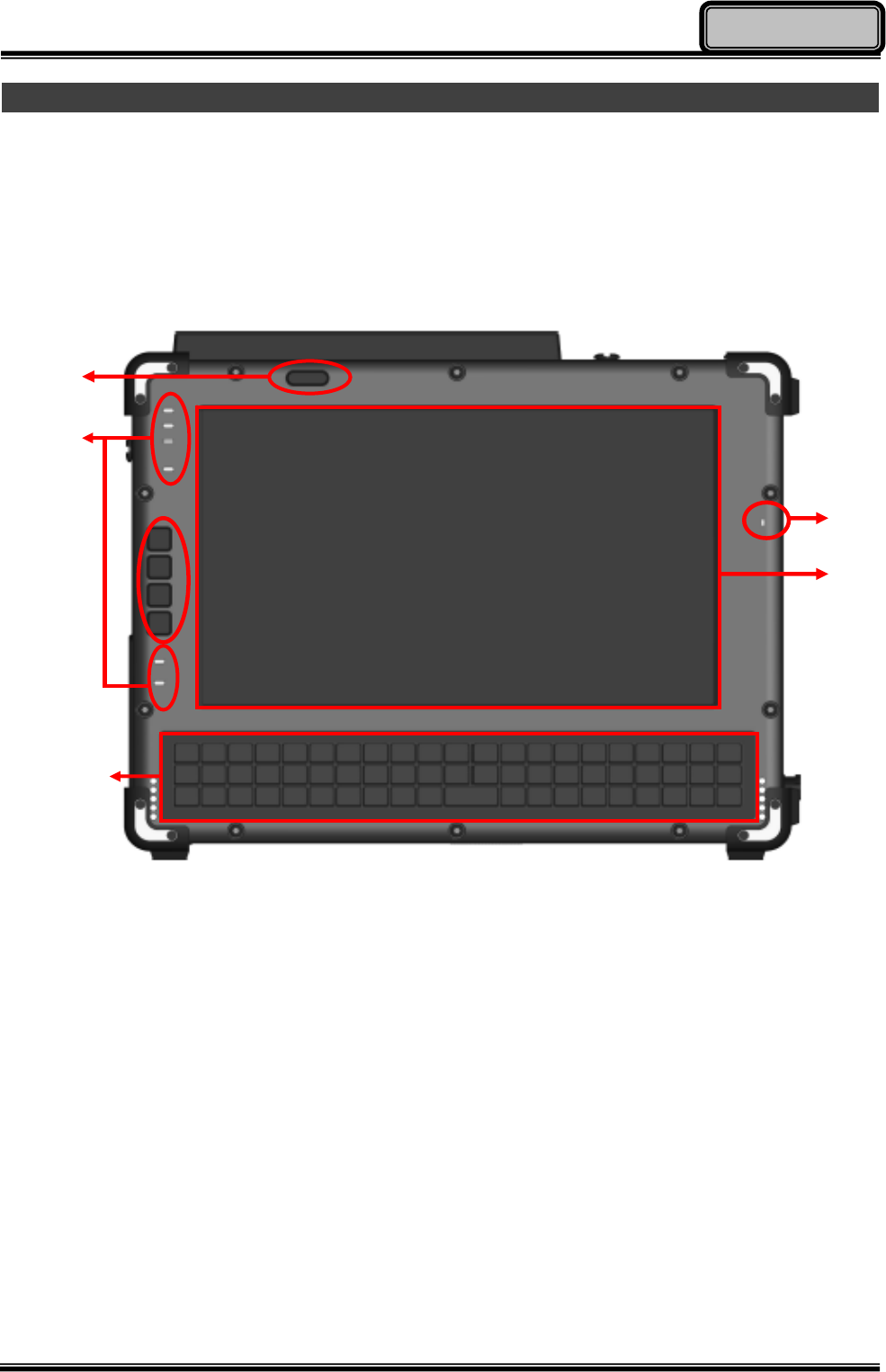
Front View
1. Power Button
2. LED Indicators
3. Application Keys & Input Lock Key (Please see page 14 for more details)
4. Microphone
5. Touch Screen
6. Keyboard
6
1
5
2
3
4
Chapter One - 4
Getting Started
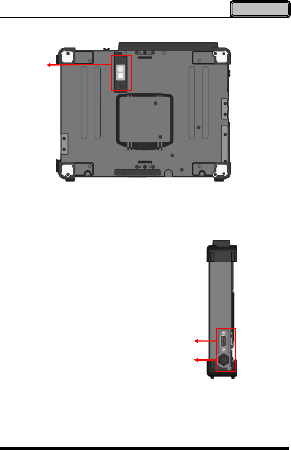
Rear View
1. Optional 2.0 MP Auto-Focus Camera with LED Flashlight
Right-Side View
1. Serial Port DB9 x 1
(Default: RS232,
RS422/RS485/TTL selectable)
2. DC Power Jack
(Default: 2-pin, optional 3-pin
Mil. Connector)
1
1
2
Chapter One - 5
Getting Started
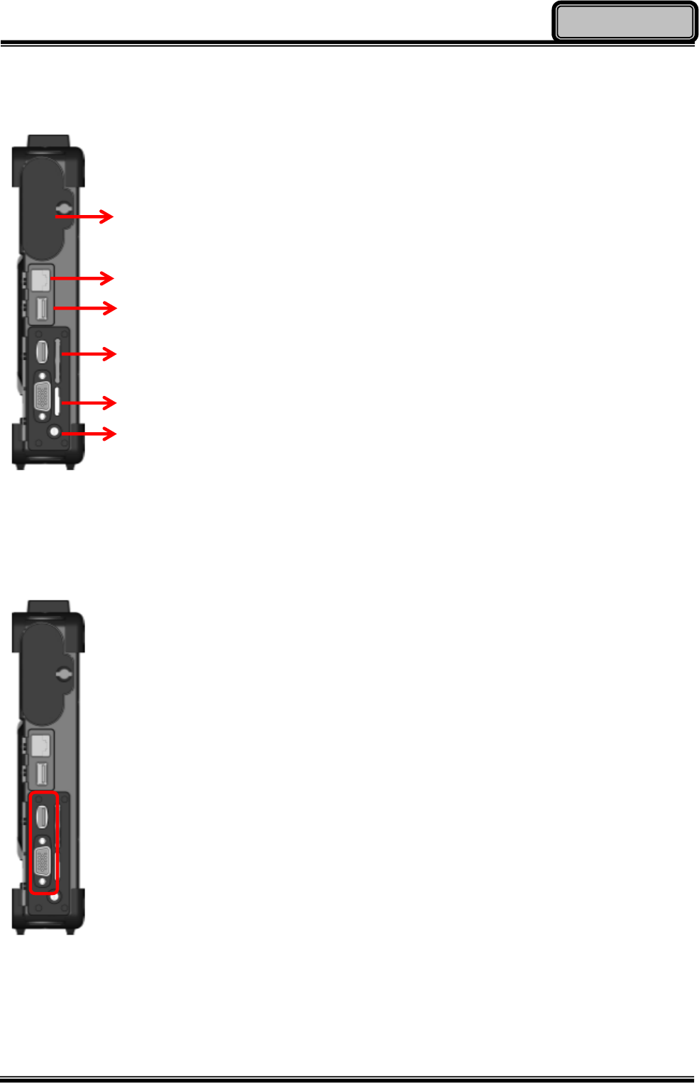
Left-Side View
1. Battery Pack
2. G-LAN Port RJ45 x 1
3. USB 2.0 Port x 1
4. SD (SDHC) Card Slot x 1
5. SIM Card Slot x 1
6. 3.5mm Audio Jack x 1
(4-Pole for Headphone and Microphone)
Left-Side Expansion Slot
Select 1 out of the following:
z RGB Port DB15 x 1 + USB 2.0 Port x 1
z Optional Smart Card Reader Slot x 1
z Optional Express Card Slot x 1
(Trade-off with WLAN Module)
1
2
3
4
5
6
Chapter One - 6
Getting Started
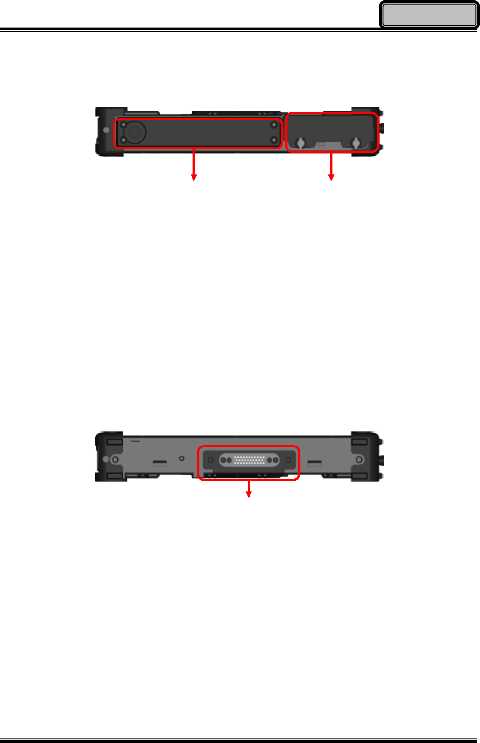
Top View
1. Antennas
z Standard Bluetooth Antenna
z Optional WLAN and GPS Antennas
2. Removable 2.5” SATA HDD/SSD
Bottom View
1. Docklight POGO Connector Port
Signals Carried:
z RS232 x 1
z USB 2.0 (Host) x 1
z RGB x 1
z DC-In x 1
1
1 2
Chapter One - 7
Getting Started
Ready for Use
After taking a quick look at your tablet computer, the following illustrations will get you ready
for using it.
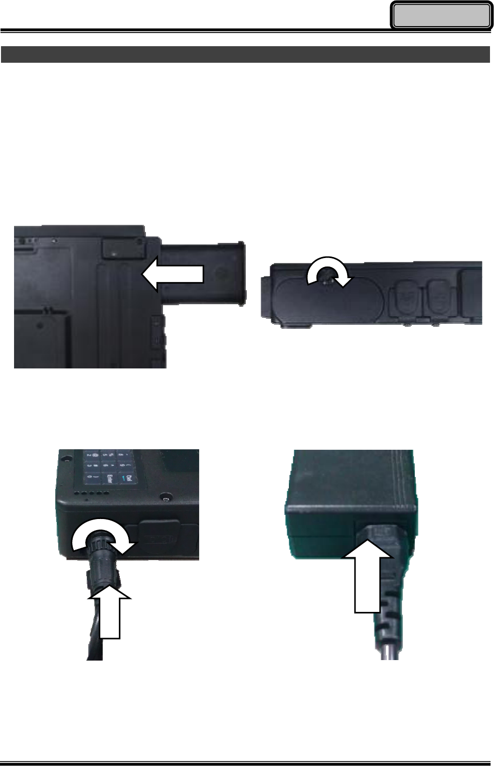
1. Mounting the Battery
A. Mount the battery into the battery bay.
B. Turn clockwise and lock firmly with a
flat-head screwdriver or a coin.
2. Connecting the AC Adapter
A. Insert the DC Jack and firmly lock
the connector clockwise.
B. Plug the AC cord into the AC adapter.
C. Plug the AC power plug into an
electrical outlet.
Chapter One - 8
Getting Started
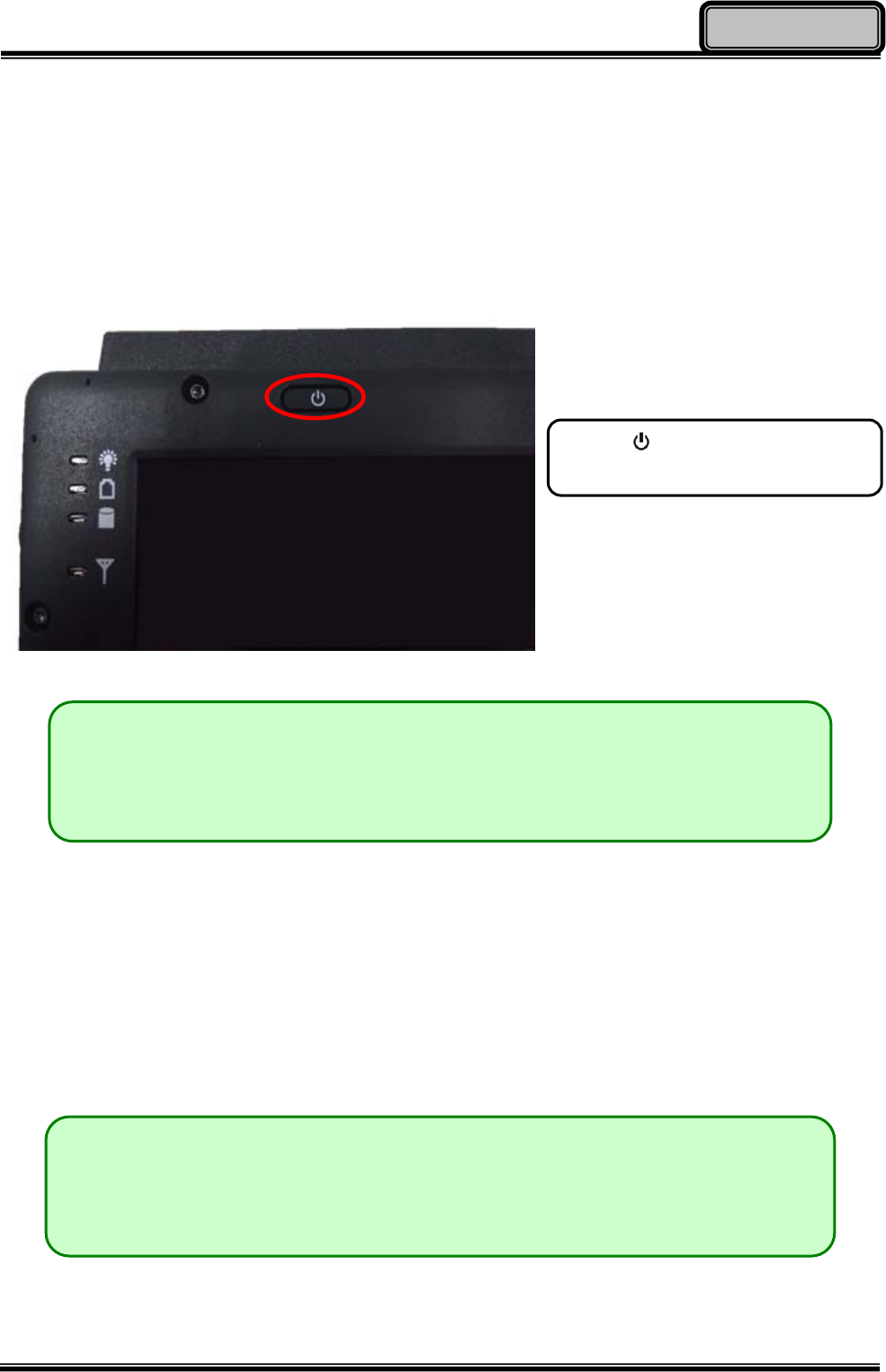
3. Turning ON the Power
A. Make sure the battery is mounted or connect all power cords well for the stable power
supply.
B. Now, you can turn ON the power of your tablet computer by pressing the “Power
Button”.
4. Turning OFF the Power
Directly click “Shut down” from your OS to turn OFF the power of your tablet computer. If
your tablet computer stops responding, press and hold the power button to “Force Shut
down” your tablet computer.
Press to turn on the power
of your tablet computer.
Note:
¾ The power is able to turn ON without any battery mounted once all the
power cords are connected.
Note:
¾ Directly turn OFF the power by “Force Shut down” will cause data lose and
is not recommended.

Chapter Two - 9
Operating Information
Chapter 2 - Operating Information
Start Using Your Computer
Always turn on your computer by using the power button. This is the standard operating
procedure to start using your computer. After turning on the power of your computer, it will
start with the Operating System (OS) installed, such as Windows 7.
Boot Up
When you turn on the power, your computer will start to load the OS into the system memory.
This start-up procedure is called “boot up”.
Power On Self-Test (POST)
Each time your computer is turned on, the BIOS will automatically perform a self-test of CPU,
memory, hardware devices, and so on.
Stop Using Your Tablet Computer
Each time when you finish working with your tablet computer, there are several ways to stop
your tablet computer from operating.
Shut down
Directly click “Shut down” from your OS to turn OFF the power of your computer. Before
shutting down, please do remember to save any unfinished works and close your
applications to prevent your HDD from suffering possible data loss or damage. “Shut down”
will turn OFF power of your computer. If you want to start your computer again, you need to
turn it ON again by pressing the power button.
Sleep
Under “Sleep” mode, the system will temporarily save your work into the computer’s RAM. If
you want to start your computer again, please press the power button to resume. You can
enter this mode by directly clicking:
“Start” => “Shut down” => “Sleep” under Windows 7.

Chapter Two - 10
Operating Information
Hibernate
Under “Hibernate” mode, the system will save your work into HDD. If you want to start your
tablet computer again, you need to press the power button. You can enter “Hibernate” mode
by pressing the power button, or by directly clicking:
“Start” => “Shut down” => “Hibernate” under Windows 7.
Force Shut Down
In the event that your tablet computer hangs or stops responding, you can perform a force
shut down by pressing and holding the power button for 4~5 seconds. Please note that any
unsaved work or data will be lost this way.
Working with Power Button (Heater Kit)
Your tablet computer is equipped with a heater kit to enable your unit to work under low
temperature. The heater will heat up the HDD to the temperature set by the user before
booting the system. Also, the heater will keep monitoring HDD temperature. Once the
temperature becomes lower, the heater will heat up again to maintain the temperature set by
user.
Note:
z When ambient temperature is under +5 °C (the default setting for your tablet computer),
the system may not boot up immediately. System will beep with HDD LED light flashing
orange to remind the user that the heater is in operation. The LED will blink faster as the
HDD temperature approaches operational temperature. After 5~15 minutes, the system
will boot up automatically.
z In emergency situations, your tablet computer can skip the heating process by pressing
and holding the power button for 9~11 seconds, then release. The speaker will beep
with a special sound to signify that the heating process has been skipped (Please note
that not all devices are guaranteed to work properly in this case).
z Press the power button again during the heating process will shut down the computer.

Chapter Two - 11
Operating Information
The following is a list of functions that are associated with your tablet computer’s power
button:
1. Press and hold for 12 seconds, then release:
USB port is enabled and you can set a new value in Heater AP.
2. Press and hold for 9 ~ 11 seconds:
The system will skip heating process and force boot up.
3. Press and hold for 5 ~ 8 seconds:
Enable/Disable the sound of Heater.
4. Press and hold the power button for 4 seconds under OS:
Shut down the system.
5. Press the power button.
a. Power on the system.
b. If pressed while the heating process is underway, the system will be forced to shut
down.
c. Entering Sleep/Hibernate under OS (this function is dependent on your OS
settings).
Installing Operating System
Your computer is designed to operate with Microsoft Windows 7 32-bit Operating System.
Please connect your computer with a suitable external USB-interface drive, such as an ODD
or a USB thumb drive, and start the OS installation.
Note:
¾ A USB hub may be required during installation to connect with an
external USB-interface ODD and Keyboard, as the System USB port
may not supply enough power. Please connect your USB hub with extra
power supply to complete the installation.
Chapter Two - 12
Operating Information
Using Indicators and Keyboard
Your tablet computer is designed with a keyboard for easy and quick operations. Also, each
LED indicator shows different meanings.
Here are the descriptions for each button and LED indicator to help you use well with your
tablet computer.
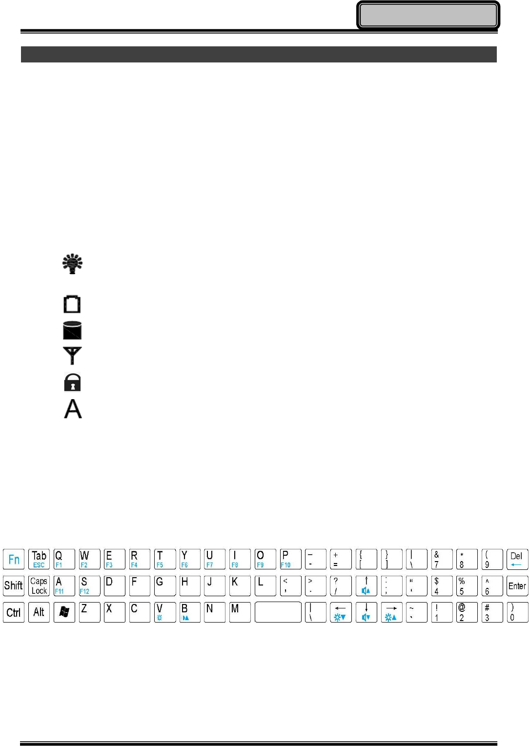
LED Indicators
Power Indicator: Green (Power); Flashing Red (S3: Standby);
Flashing Green (Battery power is lower than 15% under S3 mode)
Charger Indicator: Orange
HDD Indicator (Dual LED): Green (HDD); Orange (Heater)
Wireless Devices Indicator: Blue
Input Lock Indicator: Red
Caps Lock Indicator: Green
Keyboard
The 62 keys keyboard is a miniaturized keyboard designed to be functionally equivalent to a
full size desktop keyboard. The keyboard layout is shown below:
To perform 2nd layer combinational keystroke functions (keystroke functions printed in blue),
press and hold [Fn], then press the corresponding key combinations.

Chapter Two - 13
Operating Information
A list of useful combinational keystroke functions is provided below for operational reference:
[Fn] + [V]: Turn your tablet computer’s LCD On/Off
[Fn] + [B]: Turn your tablet computer’s keyboard backlight On/Off
[Fn] + [↑]: Increase Audio Volume
[Fn] + [↓]: Decrease Audio Volume
[Fn] + [→]: Increase LCD brightness
[Fn] + [←]: Decrease LCD brightness
[Fn] + [Del]: Backspace Key
[Fn] + [Tab]: Esc Key
[Fn] + [F1 ~ F12]: Function Key F1 ~ F12
LCD On/Off & Keyboard Backlight
To toggle LCD On/Off, press [Fn] + [V] key simultaneously to turn the LCD ON or OFF.
To toggle keyboard backlight, Press [Fn] + [B] key simultaneously to turn the keyboard
backlight ON or OFF.
Hard Disk Drive (HDD)
The Hard Disk Drive (HDD) / Solid State Drive (SSD)* is a 2.5” type / 9.5mm height standard
SATA interface data storage device.
The HDD (SSD) is removable. This design provides convenience and security. Please note
that the drive can ONLY be removed when the power is OFF.
Note:
The key “AltGr”, which is a standard key in some language keyboard layouts, is
removed due to space constraints. The function of the “AltGr” key is “Alt” + “Ctrl”
key. If you need to access “AltGr”, please press “Alt” + “Ctrl” simultaneously.

Chapter Two - 14
Operating Information
Using Application Keys & Input Lock Key
Application Keys allow functions to be performed quickly and conveniently. Your tablet
computer is equipped with 3 Application Keys and an Input Lock Key for your operational
convenience. To operate, simply press the desired AP Keys.
APP Key 1 and APP Key 3 are reserved for special projects, APP Key 2 functions as your
optional camera’s shutter, allowing you to take photos quickly and conveniently at the press
of a button.
The Input Lock can be toggled On/Off by pressing the Input Lock Key. When the Input Lock
is turned on, both your tablet computer’s keyboard and touch screen are disabled. Any input
strokes on the keyboard or touch on the screen during this time will be ignored. This is useful
when you want to prevent keys and functions from accidental activations. To turn off the
Input Lock, simply press the Input Lock Key again.
Note:
NEVER drop your HDD (SDD) or expose it to high temperature, high
humidity, or any hazardous environment. NEVER try to disassemble the
module. Static discharge may destroy your device and data. Always pick up
the modules by touching the case only.
Chapter Two - 15
Operating Information
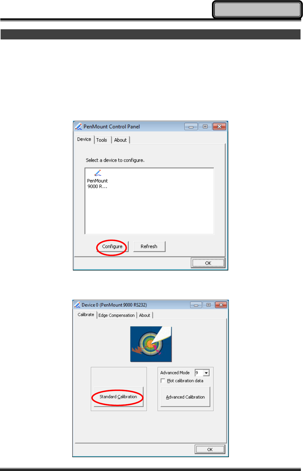
Using Touch Screen
Your tablet computer is equipped with a high sensitive touch panel allowing you to navigate
on the touch screen easily without using other external devices. Before using touch screen,
please follow the instructions below to make your stylus pen for a more precise positioning:
1. Click “Configure” to start.
2. Use “Standard Calibration” and follow the instructions.
Chapter Two - 16
Operating Information
A stylus pen is provided for you to use well with the touch screen. Here are some operating
tips to help you use the touch screen well with a stylus pen.
Single Click: Tapping the touch screen with a stylus pen gently
Double Click: Tapping the touch screen quickly twice with a stylus pen
Drag and Drop: Clicking and holding the object with a stylus pen slightly and moving
to the destination you want (Drag). Leave the stylus pen from the
touch screen once you finish dragging (Drop).
Right Click: Pressing on one point of the touch screen and hold for 2~3 seconds.
This is the same as using the right click of a mouse.
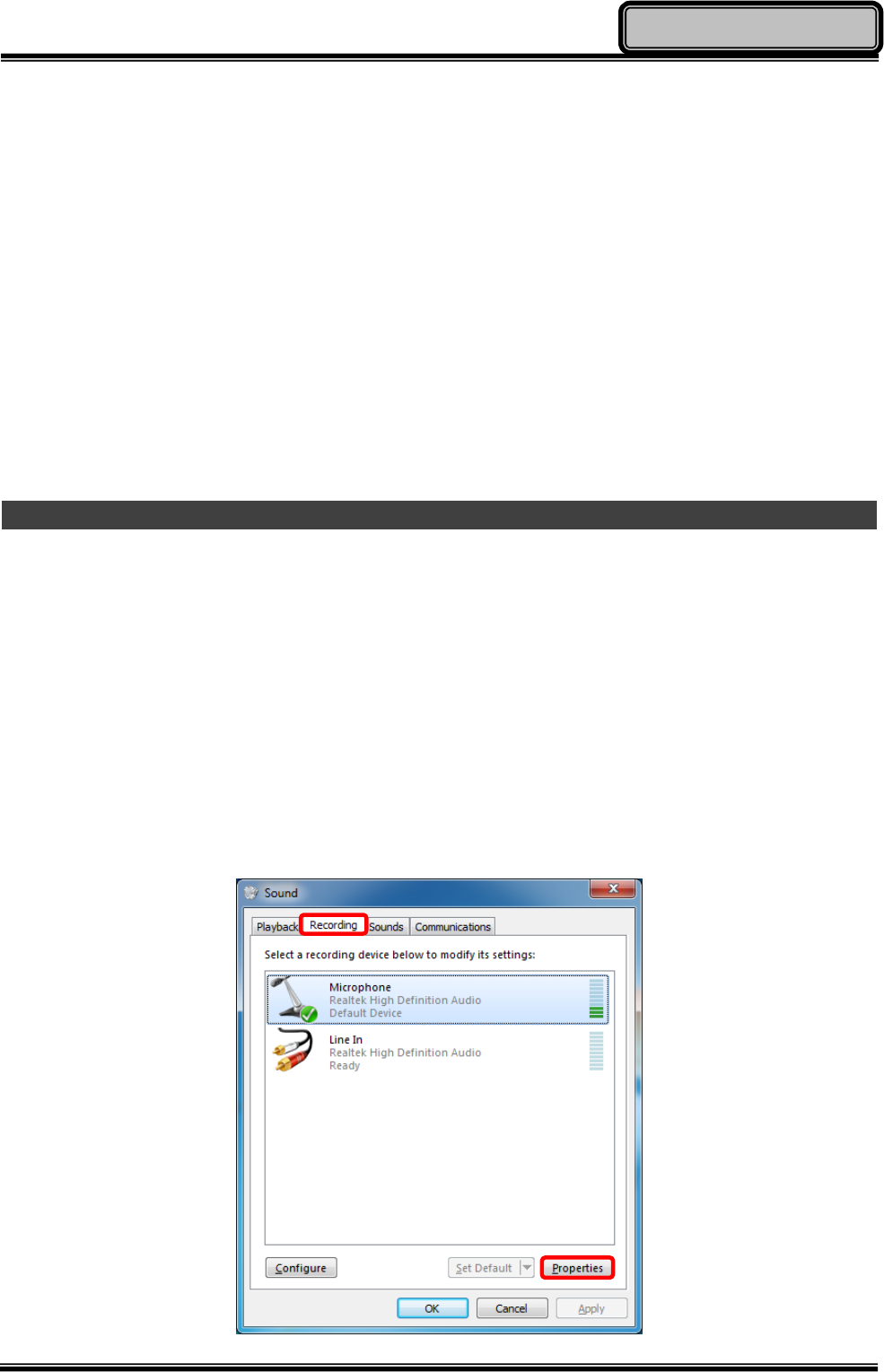
Using Your Microphone
Your tablet computer is equipped with a built-in microphone. The microphone is capable of
sound and voice recording. Please follow the instructions listed below to configure your
microphone:
1. If this is your first time using the microphone, please adjust your microphone’s DB value.
You can modify microphone settings under Control Panel => Hardware and Sound =>
Manage Audio Devices. Click on the Recording tab, select your microphone device,
and then click on Properties.
Chapter Two - 17
Operating Information
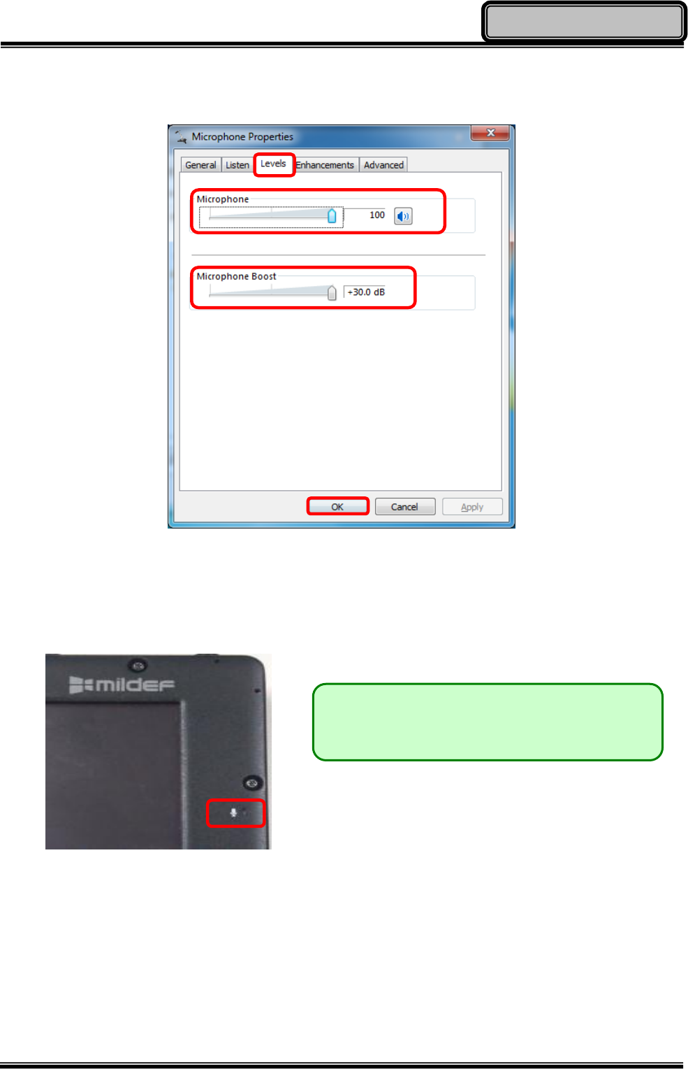
2. Under Microphone Properties window, click on the Levels tab. Adjust your microphone
volume and microphone boost to desired levels and click OK to save changes.
3. The built-in microphone of your tablet computer is located at the right side. Please bring
your tablet computer closer to the sound source(s) to achieve better recording quality.
Start recording with your recorder such as Sound Recorder in Windows 7. You can find
Sound Recorder at: “Start => All Programs => Accessories =>Sound Recorder”
Note:
¾ The microphone is located at the right.
Chapter Two - 18
Operating Information
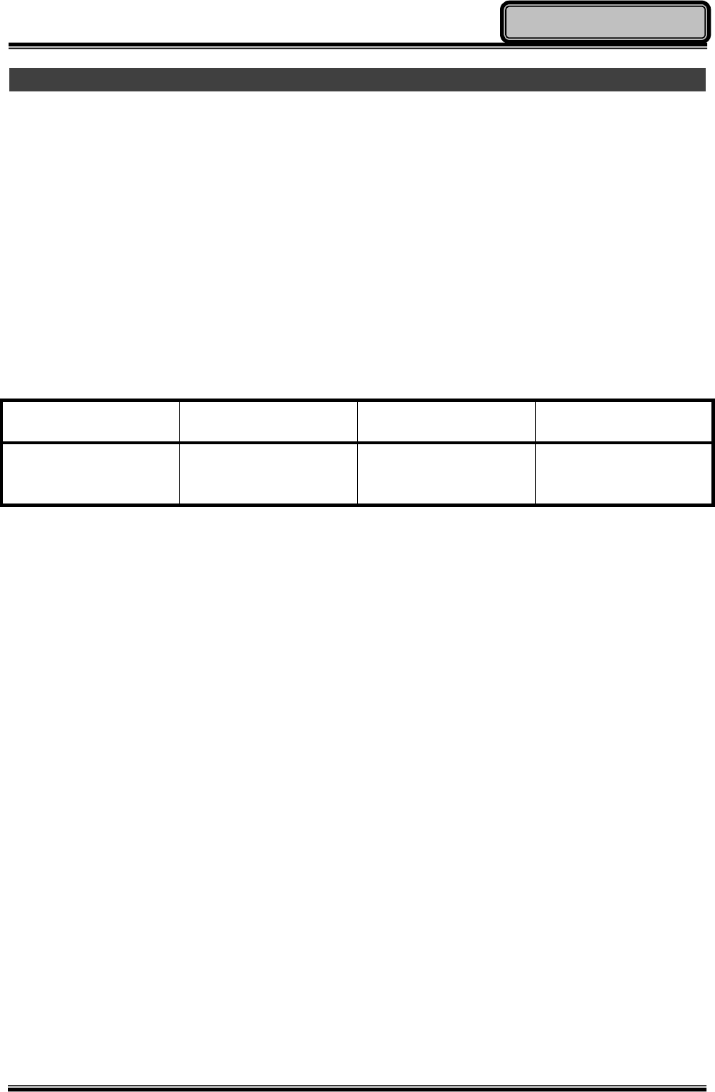
Using Audio Features
Your tablet computer is equipped with a 3.5 mm 4-pole audio jack for headset and
headphone. Please Note: The combo audio jack does not support a conventional
microphone. If a conventional headphone is attached to it, the headphone function is
supported. If a headset with a 3.5mm 4-pole plug is attached to it, both headphone and
microphone functions are supported.
The following table shows which functions of the audio devices attached to the jacks on your
computer are supported.
Headset with a 3.5
mm 4-pole plug
Conventional
headphone
Conventional
microphone
Combo audio jack Headphone and
microphone
functions supported
Headphone function
supported Not supported

Chapter Two - 19
Operating Information
Operating Wireless Devices
For the ease of operations, you can turn ON/OFF your Wireless Devices through the
proprietary application - “Device Power Manager”.
Bluetooth
A Class 2, Bluetooth® v2.1 + EDR system is backward compatible with v1.1/1.2/2.0 devices.
Bluetooth provides your tablet computer with a short-range wireless communication protocol
to connect with other compatible devices via its pre-installed embedded antenna. To activate
your Bluetooth function, please follow the instructions below.
1. Driver & Application Installation
a. Install the Bluetooth driver first. Read from the Utility DVD and find the directory in
readme to finish installation.
b. Install the Device Power Manager application. Read from the Utility DVD and find
the directory in readme to finish installation.
2. Launch the Device Power Manager
After launching the utility, please click “Bluetooth” for enabling the Bluetooth function
(click again for disabling the Bluetooth function). Once the Bluetooth function starts up,
the Wireless LED indicator will turn on in blue and the Bluetooth icon will show up in the
OS accordingly.

Chapter Two - 20
Operating Information
Wireless LAN (Optional)
Wireless LAN card is an optional device for your tablet computer. The Wireless LAN
supports IEEE 802.11 a/b/g/n, an embedded antenna will be pre-installed in your tablet
computer to access the internet wirelessly. To activate your Wireless LAN function, please
follow the illustrations below:
1. Driver & Application Installation
a. Install the Chipset Driver first. Read from the Utility DVD and find the directory in
readme to finish installation.
b. Then, install the Device Power Manager application. Read from the Utility DVD and
find the directory in readme to finish installation.
2. Launch the Device Power Manager
After launching the utility, please click “Wireless LAN” for enabling the Wireless LAN
function (click again for disabling the Wireless LAN function).
Once the Wireless LAN function starts up, the Wireless Device LED indicator will turn on in
blue and the Wireless LAN icon will show “connected” in the OS accordingly.

Chapter Two - 21
Operating Information
GPS (Optional)
GPS is an optional module for your tablet computer. This GPS module supports GPS and
Galileo systems. An embedded antenna is pre-installed in your tablet computer to support
the functions of your GPS.
Driver & Application Installation:
a. Install the Device Power Manager application:
Read from the Utility DVD and find the directory in readme to finish installation.
b. Install the GPS driver:
z GPS (Driver): Read from the Utility DVD and find the directory in readme to finish
installation.
z GPS (Application): Read from the Utility DVD and find the directory in readme to
finish installation.
c. Install the Device Power Manager Application:
Read from the Utility DVD and find the directory in readme to finish installation.
Chapter Two - 22
Operating Information
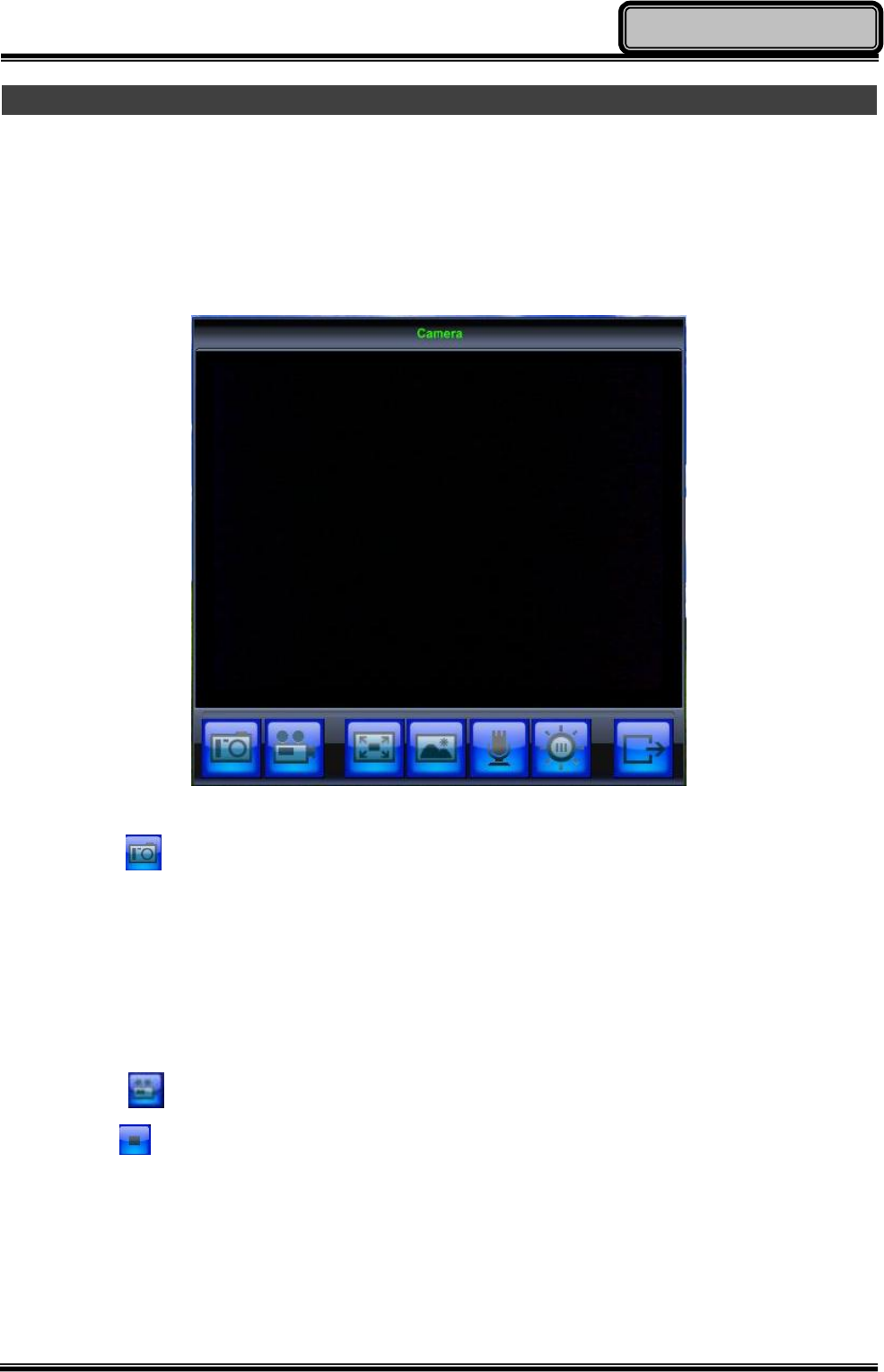
Using Your Camera (Optional)
Your tablet computer provides an optional 2 million-pixel CMOS camera for you to capture
images at any time. The camera also supports video recording function. You are able to
press the camera button or application menu button to enter the camera window as below:
Taking Pictures
Click on the icon in the camera window to take pictures. Or, you can press the camera
button again to capture the images. After taking pictures, your pictures will automatically be
saved in:
C:\Documents and Settings\Administrator\My Document\My Pictures
Recording Videos
Click on the icon in the camera window to recording video. To stop recording, please
click on the icon. While recording, you can also adjust the volume. After recording video,
your video files will automatically be saved in: C:\Documents and Settings\Administrator\My
Document\My Video
Chapter Two - 23
Operating Information
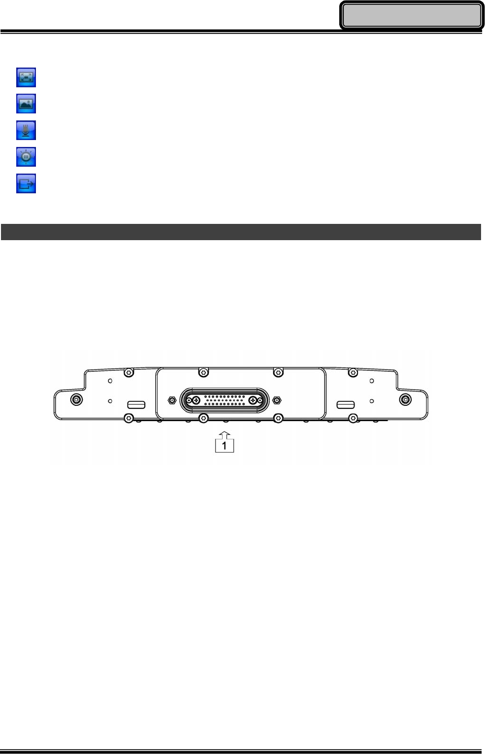
Other Functions
Video Format Properties: Advanced video format adjusting
Image Properties: Advanced image settings and camera control
Volume Level: Adjust video recording volume
Flash LED Settings: Advanced flash LED settings
Exit: Exit the camera window/ function
Using Docklight DLDT (Optional)
The Docklight DLDT is an optional add-on docking and port-expansion unit designed for
your tablet computer. The Docklight DLDT also supports hot-plug.
Docklight Ports (Top View)
Docklight provides the following port expansions:
1. POGO Connector x 1
Chapter Two - 24
Operating Information
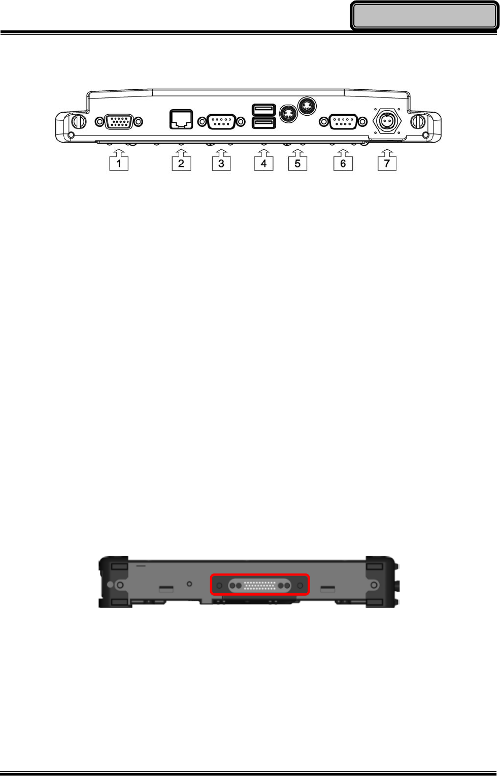
Docklight Ports (Bottom View)
1. RGB Port x 1
2. Mega LAN x 1
3. COM Port x 1 (USB to COM. Default: RS232, Selectable RS422/RS485/TTL)
4. USB Port x 2
5. Sealed USB Port x 2
6. COM Port x 1 (Default: RS232, Selectable RS422/RS485/TTL)
7. DC Power Jack x 1
Mounting the Docklight
The procedures for mounting the Docklight with your tablet computer are as follows:
1. Turn off the power of your tablet computer.
2. Align the docking connectors. The docking connector of your tablet computer can be
found at the bottom side of the unit.
Chapter Two - 25
Operating Information
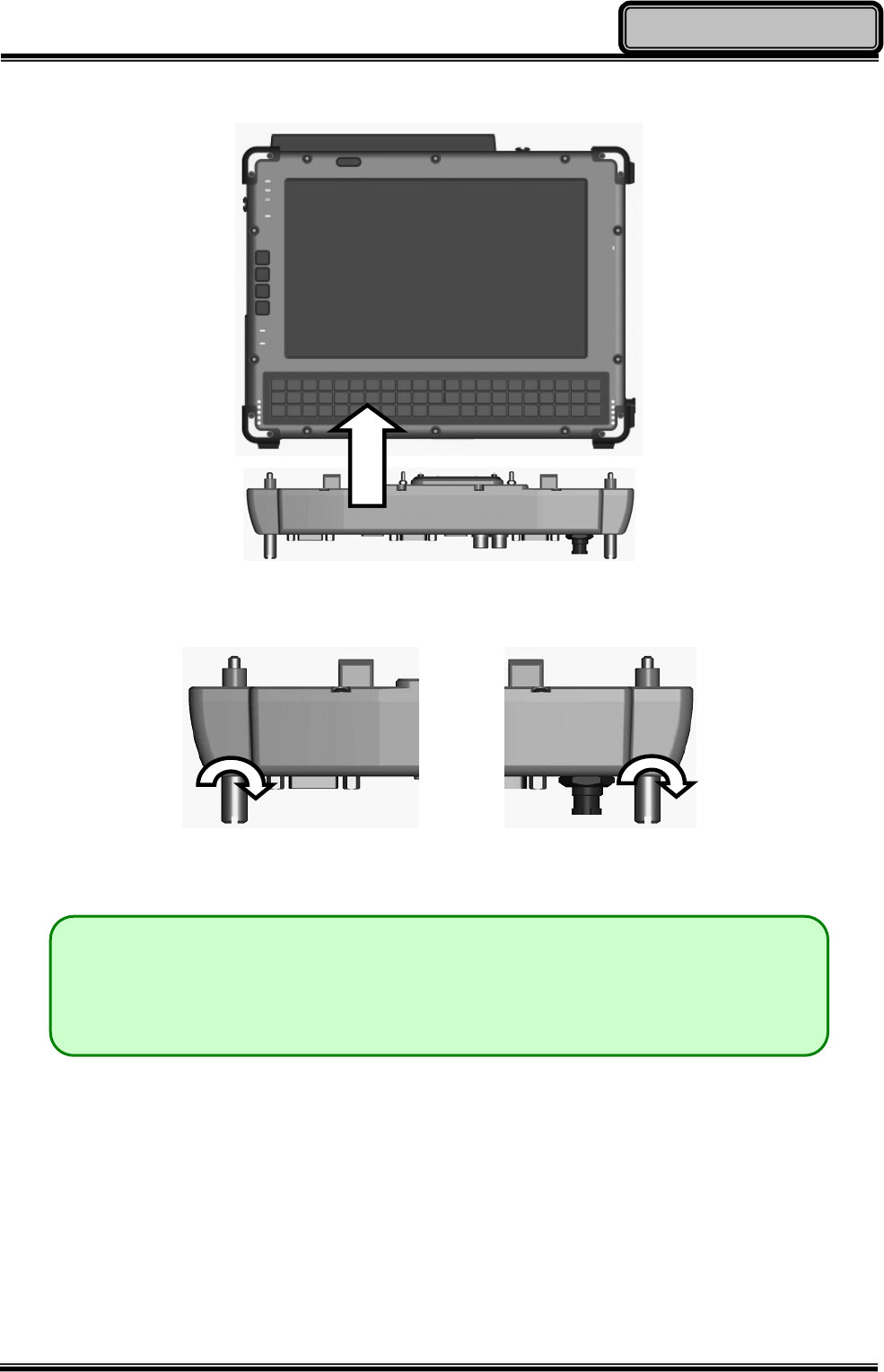
3. Firmly engage the Docklight with your tablet computer.
4. Tighten the connecting bolts on both ends of the Docklight by turning the bolts clockwise
(turn counter-clockwise to loosen).
5. Turn on the power on your tablet computer to complete the Docklight installation.
Note:
¾ When mounting the Docklight, it is recommended that the tablet computer
be turned upside-down for easier installation.

Chapter Three 26
Managing Power
Chapter 3 - Managing Power
AC Adapter
The AC adapter performs two functions:
z It powers the computer from an external AC source.
z It charges the computer battery.
The adapter automatically detects the AC line voltage (100V or 240V) and adjusts
accordingly.
The following are recommended when using the AC adapter:
z Use a properly grounded AC outlet.
z Use one AC outlet exclusively for the computer. Having other appliances on the same
line may cause interference.
z Use a power strip with built-in surge protection.
Connecting the AC adapter:
z Plug the AC cord to the adapter.
z Plug the other end of the AC cord into the wall outlet. Make sure the green LED on the
adapter turns on.
z Attach the DC plug into the power jack of the computer; turn the lock ring clockwise to
secure it.
AC Adapter Indicator:
The green LED indicates that AC power is ready.
Chapter Three 27
Managing Power
Battery
The power source will automatically switch to battery when the external power source (AC
adapter or optional vehicle adapter) is disconnected.
Battery Low
When the battery is nearly exhausted, the computer gives the following “Battery Low”
warnings:
z Windows battery low warning (when operating system is Windows).
z The power LED flashes.
Once the Battery Low warning occurs, please:
z Save and close the files you are currently working on.
z Plug in the AC adapter to recharge the battery.
Charging the Battery
Plug in the AC adapter (or optional vehicle adapter) to start the battery charging. If the
battery is already full, the sense circuitry will stop high current charge within several minutes.
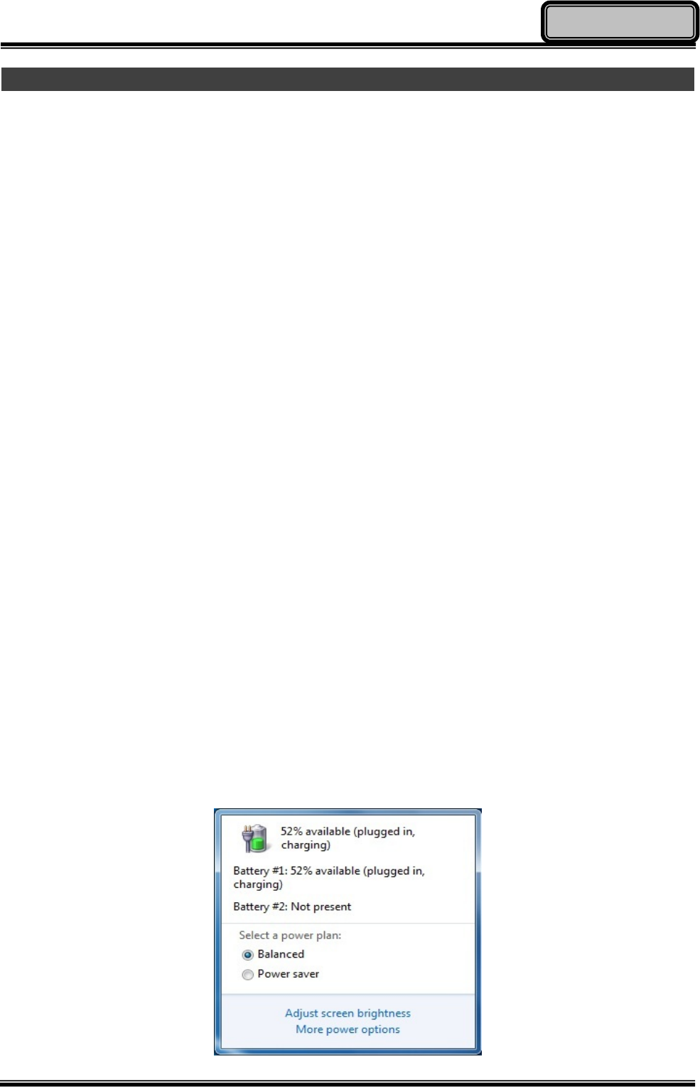
Battery Gauge
You may check battery status from battery gauge in Windows. Click the power/battery icon
to reveal the battery gauge window.

Chapter Three 28
Managing Power
Battery Power Saving Tips
The computer comes with an intelligent power-saving feature. You may extend the battery
life by:
z Setup power saving features in Operating System Power Management options (e.g.
Windows Power Options).
z Lower the intensity of the display by brightness control.
z Use Sleep/Hibernate option when computer is temporarily not in use.
z Shut down the computer when not in use for extended period of time.
Replacing Battery
When the battery is nearly exhausted, there are two ways to keep your tablet computer
working. Connect the AC adapter and the power cord designed for this tablet computer to
start charging is one method; directly replace a charged battery designed for this tablet
computer may be the other one.
Note:
¾ Always remember to turn OFF the power before replacing the battery.

Chapter Three 29
Managing Power
Power Conservation
This tablet computer consumes less power compared to conventional consumer computers.
The power consumption may be further reduced by properly configuring the Power
Management Setup.
It is recommended that the power saving features be enabled even when not running on
battery power. Power Management features can conserve power without degrading system
performance.
ACPI Support
Your computer supports ACPI (Advanced Configuration and Power Interface) for power
management. With ACPI and an ACPI-compliant operating system (such as Microsoft
Windows), this feature will allow you to reduce the power consumption and conserve energy.
By supporting ACPI, the AC adapter LED and the Power indicator LED will show in different
ways. The followings are detailed descriptions of LED indicators and their meanings:
Sleep:
Power LED indicator is blinking RED; Other LED indicators are OFF
Hibernate:
All LED indicators are OFF
Shut down:
All LED indicators are OFF

Chapter Four 30
BIOS Setup
Chapter 4 - BIOS Setup
If you wish to change the BIOS settings of your tablet computer, turn on the power of your
tablet computer and press “Del” key on your Mini Keyboard during boot-up sequence to
enter the BIOS Setup Utility.
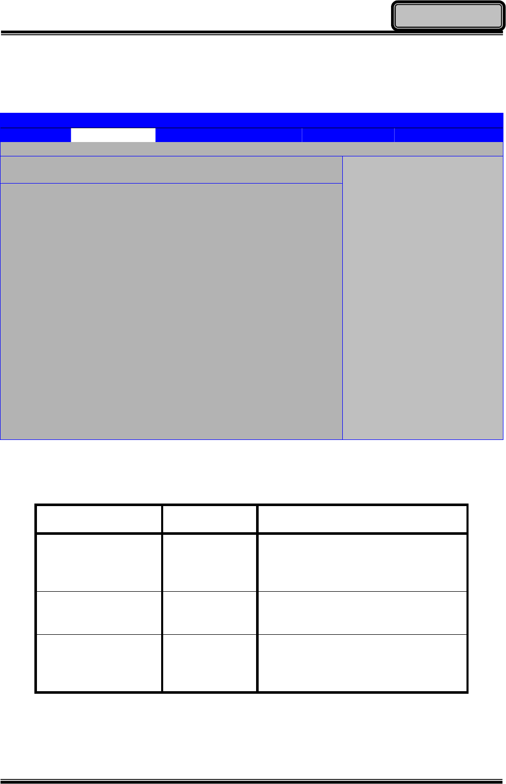
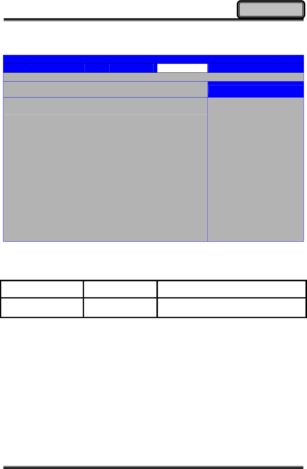
Main Menu
In Main Menu, you can access the System Overview as well as the operating instructions.
BIOS SETUP UTILITY
Main Advanced Boot Security Chipset Exit
System Overview
AMIBIOS
Version :08.00.15
Build Date :11/03/11
ID :1AAAA000
Processor
Intel(R) Atom(TM) CPU Z530 @ 1.60GHz
Speed :1600MHz
Count :1
System Memory
Size :2039MB
System Time [16:15:25]
System Date [Tue 11/29/2011]
CMC Lo-Module: OD2.026x, Hi-Module:OD2.018x
Use [Enter], [TAB]
or [SHIFT-TAB] to
select a field.
Use [+] or [-] to
configure system Time.
← Select Screen
↑↓ Select Item
+- Change Field
Tab Select Field
F1 General Help
F10 Save and Exit
ESC Exit
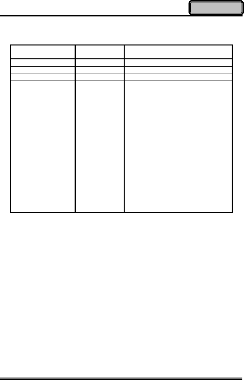
Main Menu Selections
You can make the following changes under the Main Menu Selections.
Feature Options Description
System Time HH:MM:SS Set the system time Hour, Minute,
Second.
System Date MM/DD/YYYY Set the system date Month, Day, and
Year.

Chapter Four 31
BIOS Setup
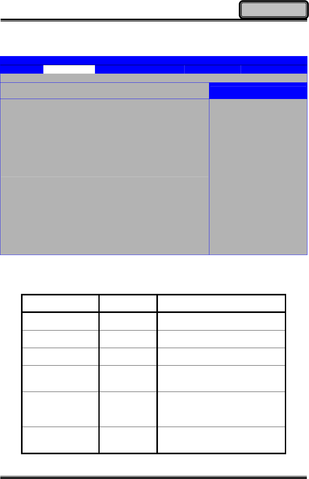
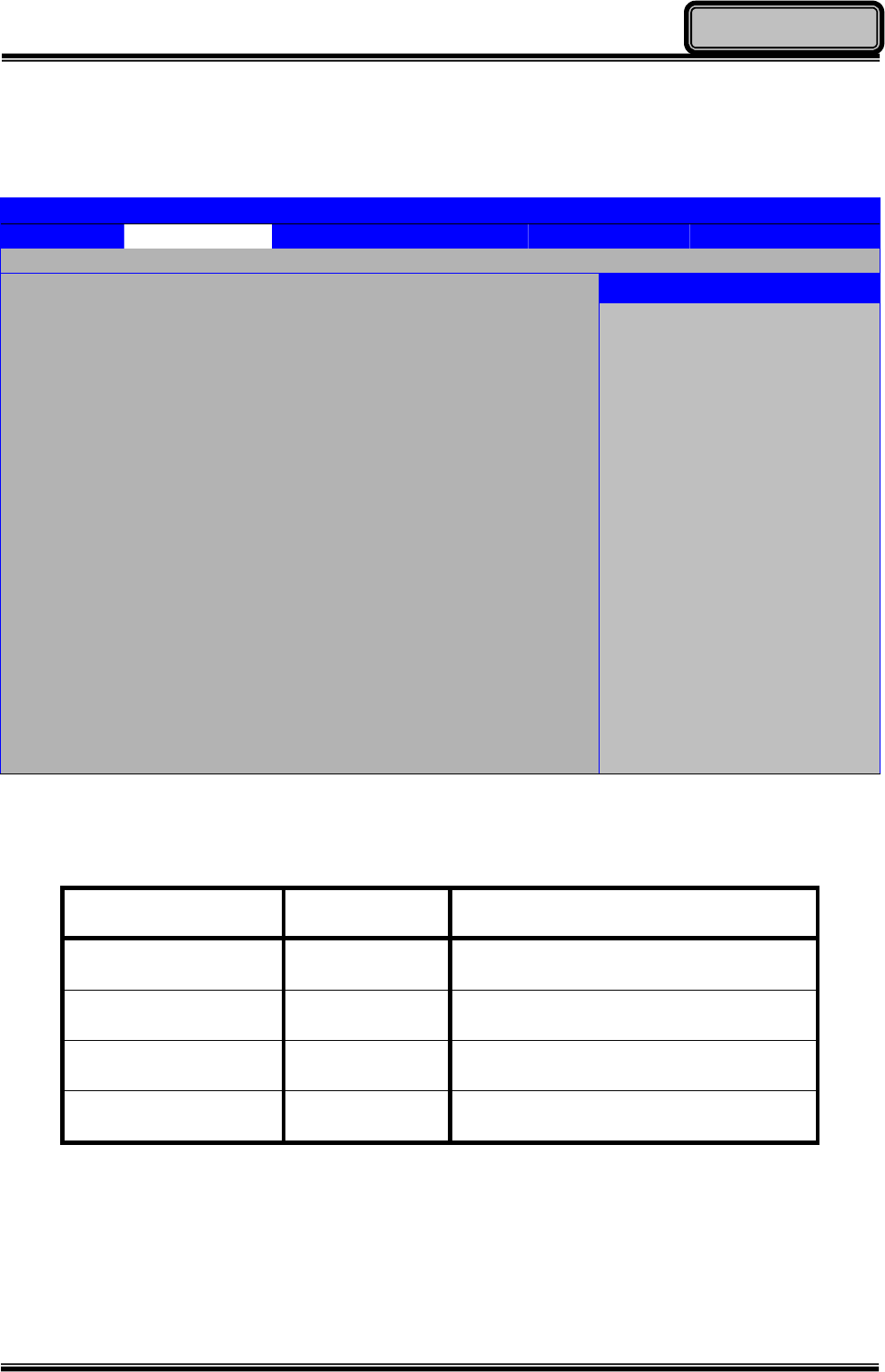
Advanced Menu
In Advanced Menu, you can access the following advanced settings.
BIOS SETUP UTILITY
Main Advanced Boot Security Chipset Exit
Advanced Settings
Warning: Setting wrong values in below sections
may cause system to malfunction.
► IDE Configuration
► SuperIO Configuration
► USB Configuration
► DEVICES Control
Thermal cooling trip point [79C]
Critical trip point [103C]
Installed O/S [Windows 7]
Configure the IDE
device (s).
← Select Screen
↑↓ Select Item
Enter Go to Sub Screen
F1 General Help
F10 Save and Exit
ESC Exit
Chapter Four 32
BIOS Setup
Advanced Menu Selections
You can make the following changes under the Advanced Menu Selections.
Feature Options Description
IDE Configuration Configure the IDE device (s).
SuperIO Configuration Configure SuperIO Chipset SMC227.
USB Configuration Configure the USB support.
DEVICES Control Configure the onboard devices.
Thermal cooling trip
point
z 15c
z 23c
z 31c
z 39c
z 47c
z 55c
z 63c
z 71c
z 79c
z 87c
z 95c
z 103c
z 111c
z 119c
This value controls the temperature of
the Thermal cooling trip point.
Critical trip point
z 15c
z 23c
z 31c
z 39c
z 47c
z 55c
z 63c
z 71c
z 79c
z 87c
z 95c
z 103c
z 111c
z 119c
z 127c
This value controls the temperature of
the Critical trip point.
Installed O/S Win XP/Dos
Windows 7
Linux Configures the installed O/S.
Chapter Four 33
BIOS Setup
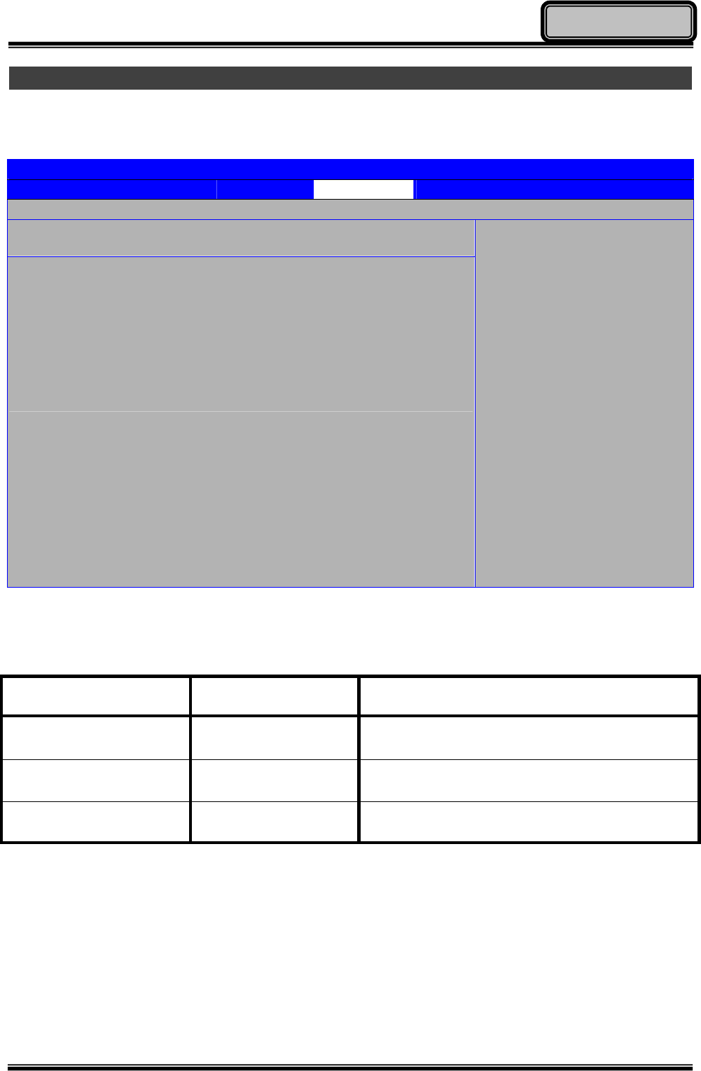
IDE Configuration Sub-Menu
In IDE Configuration Sub-Menu, you can change the configuration of your IDE devices.
BIOS SETUP UTILITY
Main Advanced Boot Security Chipset Exit
IDE Configuration Options
ATA/IDE Configuration [Compatible]
► Primary IDE Master : [Hard Disk]
► Primary IDE Slave : [Not Detected]
Hard Disk Write Protect [Disabled]
IDE Detect Time Out (Sec) [35]
ATA(PI) 80Pin Cable Detection [Device]
Disabled
Compatible
← Select Screen
↑↓ Select Item
+- Change Option
F1 General Help
F10 Save and Exit
ESC Exit
IDE Configuration Sub-Menu Selections
You can make the following changes under the IDE Configuration Sub-Menu Selections.
Feature Options Description
ATA/IDE
Configuration Disabled
Compatible Enable or disable ATA/IDE
compatibility.
Primary IDE Master Configure the Primary IDE Master
device.
Primary IDE Slave Configure the Primary IDE Slave
device.
Hard Disk Write
Protect Disabled
Enabled
Disable/Enable device write
protection. This will be effective only
if device is accessed through BIOS.
IDE Detect Time Out
(Sec)
z 0
z 5
z 10
z 15
z 20
z 25
z 30
z 35
Select the time out value for
detecting ATA/ATAPI device (s).
ATA(PI) 80Pin Cable
Detection
Host & Device
Host
Device
Configure whether Host, Device, or
Host & Device should be allowed to
detect the type of IDE cable used.

Chapter Four 34
BIOS Setup
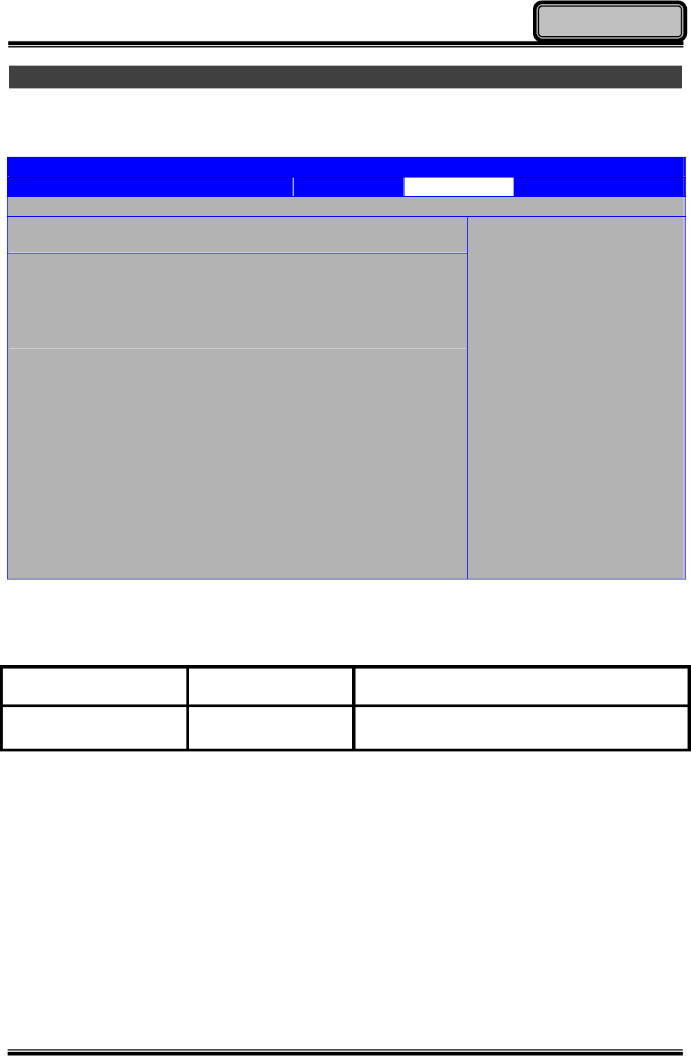
Primary IDE Master (Slave) Sub-Menu
In Primary IDE Master (Slave) Sub-Menu, you can change specific settings, such as mode
and rate of data transfer, of your IDE devices.
BIOS SETUP UTILITY
Main Advanced Boot Security Chipset Exit
Primary IDE Master
Device :Hard Disk
Vendor :Toshiba MK5065GSX
Size :500.1GB
LBA Mode :Supported
Block Mode :16 Sectors
PIO Mode :4
Async DMA :MultiWord DMA-2
Ultra DMA :Ultra DMA-5
S.M.A.R.T :Supported
Type [Auto]
LBA/Large Mode [Auto]
Block (Multi-Sector Transfer) [Auto]
PIO Mode [Auto]
DMA Mode [Auto]
S.M.A.R.T. [Auto]
32Bit Data Transfer [Auto]
Select the type
of device connected
to the system.
← Select Screen
↑↓ Select Item
+- Change Option
F1 General Help
F10 Save and Exit
ESC Exit

Chapter Four 35
BIOS Setup
Primary IDE Master (Slave) Sub-Menu Selections
You can make the following changes under the Primary IDE Master Sub-Menu Selections.
You can change the configuration of your Primary IDE Master (Slave) devices. Please note
that the Primary IDE Slave Sub-Menu Selection is identical to the Primary IDE Master
Sub-Menu Selection.
Feature Options Description
Type
Not Installed
Auto
CD/DVD
ARMD
Select the type of device connected
to the system.
LBA/Large Mode Disabled
Auto
Disabled: Disables LBA Mode.
Auto: Enables LBA mode if the
device supports it and the device is
not already formatted with LBA
mode disabled.
Block (Multi-Sector
Transfer) Disabled
Auto
Disabled: The Data transfer from
and to the device occurs one sector
at a time.
Auto: The Data transfer from and to
the device occurs multiple sectors at
a time if the device supports it.
PIO Mode
Auto
0
1
2
3
4
Select PIO mode.
DMA Mode
Auto
SWDMA0
SWDMA1
SWDMA2
MWDMA0
MWDMA1
MWDMA2
UDMA0
UDMA1
UDMA2
UDMA3
UDMA4
UDMA5
Select DMA Mode.
Auto: Auto detected
SWDMAn: SingleWordDMAn
MWDMAn: MultiWordDMAn
UDMAn: UltraDMAn
S.M.A.R.T. Auto
Disabled
Enabled
S.M.A.R.T. stands for
Self-Monitoring, Analysis and
Reporting Technology.
32Bit Data Transfer Disabled
Enabled Enable/Disable 32-bit Data Transfer.
Chapter Four 36
BIOS Setup
Super IO Configuration Sub-Menu
In Super IO Configuration Sub-Menu, you can change the configuration of your COM ports
BIOS SETUP UTILITY
Main Advanced Boot Security Chipset Exit
Configure SMC227 Super IO Chipset
COM 1 Mode Setting [RS232]
COM 1 Mode Setting [RS232]
mode options:
[RS232] :
External Device
[TTL1] :
Internal Device
[RS422] :
External Device
[RS485] :
External Device
← Select Screen
↑↓ Select Item
+- Change Option
F1 General Help
F10 Save and Exit
ESC Exit
Super IO Configuration Sub-Menu Selections
You can make the following changes under the Super IO Configuration Sub-Menu
Selections.
Feature Options Description
COM 1 Mode Setting
RS232
RS422
RS485
TTL1
Configure the mode of operation for
COM 1 port.
COM 2 Mode Setting
RS232
RS422
RS485
TTL1
Configure the mode of operation for
COM 2 port.
Chapter Four 37
BIOS Setup
USB Configuration Sub-Menu
In USB Configuration Sub-Menu, you can change the configuration of your USB module and
devices.
BIOS SETUP UTILITY
Main Advanced Boot Security Chipset Exit
USB Configuration
Module Version – 2.23.4-13.4
USB Devices Enabled :
2 Hubs
Legacy USB Support [Enabled]
USB 2.0 Controller Mode [HiSpeed]
BIOS EHCI Hand-Off [Enabled]
Enable support for
legacy USB. AUTO
option disables
legacy support if
no USB devices are
connected.
← Select Screen
↑↓ Select Item
+- Change Option
F1 General Help
F10 Save and Exit
ESC Exit
USB Configuration Sub-Menu Selections
You can make the following changes under the USB Configuration Sub-Menu Selections.
Feature Options Description
Legacy USB Support Disabled
Enabled
Auto
Enable support for legacy USB.
AUTO option disables legacy
support if no USB devices are
connected.
USB 2.0 Controller
Mode FullSpeed
HiSpeed
Configure the USB 2.0 controller in
HiSpeed (480Mbps) or FullSpeed
(12Mbps).
BIOS EHCI Hand-Off Disabled
Enabled
This is a workaround for OSes
without EHCI hand-off support. The
EHCI ownership change should
claim by EHCI driver.
Chapter Four 38
BIOS Setup
DEVICES Control Sub-Menu
In DEVICES Control Sub-Menu, you can change the configuration of your onboard devices,
such as WLAN, GPS, Bluetooth, or Camera.
BIOS SETUP UTILITY
Main Advanced Boot Security Chipset Exit
Options
Wireless Lan [OFF]
GPS [OFF]
BLUETOOTH [ON]
CAMERA [OFF]
OFF
ON
← Select Screen
↑↓ Select Item
+- Change Option
F1 General Help
F10 Save and Exit
ESC Exit
DEVICES Control Sub-Menu Selections
You can make the following changes under the DEVICES Control Sub-Menu Selections.
Feature Options Description
Wireless Lan OFF
ON Toggle Wireless Lan device
ON/OFF.
GPS OFF
ON Toggle GPS device ON/OFF.
BLUETOOTH OFF
ON Toggle Bluetooth device ON/OFF.
CAMERA OFF
ON Toggle Camera device ON/OFF.

Chapter Four 39
BIOS Setup
Boot Menu
In Boot Menu, you can access the following boot settings.
BIOS SETUP UTILITY
Main Advanced Boot Security Chipset Exit
Boot Settings
1st Boot Device [USB]
2nd Boot Device [SATA: PM-TOSHIBA MK]
3rd Boot Device [CD/DVD]
4th Boot Device [Removable Dev.]
5th Boot Device [Network: Realtek Bo]
Specifies the boot
sequence from the
available devices.
A device enclosed in
parenthesis has been
disabled in the
corresponding type
menu.
← Select Screen
↑↓ Select Item
+- Change Option
F1 General Help
F10 Save and Exit
ESC Exit
Your tablet computer will attempt to boot from the available boot devices in sequence. This
feature is useful when you wish to boot your tablet computer from alternative boot devices
for troubleshooting, maintenance or service.
Chapter Four 40
BIOS Setup
Security Menu
In Security Menu, you can access the following security settings.
BIOS SETUP UTILITY
Main Advanced Boot Security Chipset Exit
Security Settings
Supervisor Password :Not Installed
User Password :Not Installed
Change Supervisor Password
Change User Password
Boot Sector Virus Protection [Disabled]
Install or Change the
password.
← Select Screen
↑↓ Select Item
Enter Change
F1 General Help
F10 Save and Exit
ESC Exit
You can setup Supervisor Password, User Password, as well as Disable/Enable Boot Sector
Virus Protection.
Feature Options Description
Change Supervisor
Password Supervisor Password controls access to the
BIOS setup utility.
Change User
Password User Password controls access to boot the
tablet computer.
Boot Sector Virus
Protector Disabled
Enabled Enable/Disable Boot Sector Virus
Protection.
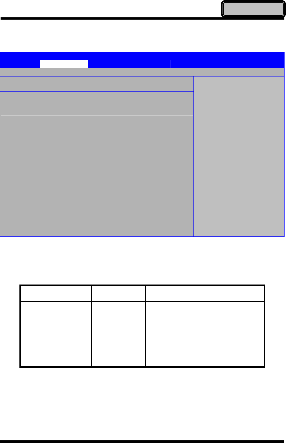
Chapter Four 41
BIOS Setup
Chipset Menu
In Chipset Menu, you are able to do the chipset option settings.
BIOS SETUP UTILITY
Main Advanced Boot Security Chipset Exit
Advanced Chipset Settings
WARNING: Setting wrong values in below sections may
cause system to malfunction.
►South Bridge Configuration
Configure South Bridge
features.
← Select Screen
↑↓ Select Item
Enter Go to Sub Screen
F1 General Help
F10 Save and Exit
ESC Exit
Chipset Menu Selections
You can make the following changes under the Chipset Menu Selections.
Feature Options Description
South Bridge
Configuration
Configures the South Bridge.
Chapter Four 42
BIOS Setup
South Bridge Configuration Sub-Menu
In South Bridge Configuration Sub-Menu, you can change the South Bridge Configuration.
BIOS SETUP UTILITY
Main Advanced Boot Security Chipset Exit
South Bridge Configuration Options
USB Client Controller [Disabled]
Enabled
Disabled
← Select Screen
↑↓ Select Item
+- Change Option
F1 General Help
F10 Save and Exit
ESC Exit
South Bridge Configuration Sub-Menu Selections
You can make the following changes under the DEVICES Control Sub-Menu Selections.
Feature Options Description
USB Client Controller Disabled
Enabled Enable or Disable USB Client Controller.

Chapter Four 43
BIOS Setup
Exit Menu
In Exit Menu, you access the following exit option settings.
BIOS SETUP UTILITY
Main Advanced Boot Security Chipset Exit
Exit Options
Save Changes and Exit
Discard Changes and Exit
Discard Changes
Load Optimal Defaults
Load Failsafe Defaults
Exit system setup
after saving the
changes.
F10 key can be used
for this operation.
← Select Screen
↑↓ Select Item
Enter Go to Sub Screen
F1 General Help
F10 Save and Exit
ESC Exit
You can save, discard, and load BIOS settings of your tablet computer here. Any unsaved
changes to the BIOS setting will be discarded.

Chapter Five - 44
Drivers and Applications
Chapter 5 - Drivers and Applications
The Utility DVD includes all the drivers for the installed devices in your tablet computer.
Please consult the dealer if there is any driver missing. Also, through Device Manager in
Windows, you are able to perform “Driver Update” or check if there are still drivers for the
devices needed to be installed. Please check the readme file on Utility DVD to get the latest
information before installing device drivers.
Chipset
To install appropriate chipset drivers for your tablet computer, please read from the Utility
DVD and find the directory in readme. Follow the instructions to complete the chipset drivers
installation.
Graphics Controller
Your tablet computer supports Intel® GMA500 graphics controller, giving you a flexible,
programmable architecture that supports high-definition video decoding and image
processing. Please read from the Utility DVD and find the directory in readme and follow the
instructions to finish installation.
Audio
Your tablet computer provides a high-quality audio sound effect for user to enjoy better
sound quality. To activate this function, please read from the Utility DVD and find the
directory in readme to finish installation.
Note:
¾ Please install the chipset driver first.
¾ If the system requests for reboot after installing drivers, please reboot
your tablet computer first before installing other drivers.

Chapter Five - 45
Drivers and Applications
Wireless Devices
Your tablet computer supports wireless communication. Bluetooth is a standard equipped
wireless device. If your model supports optional wireless connection, please see the
following to install the drivers and applications.
Bluetooth
Please read from the Utility DVD and find the directory in readme to finish installation.
WLAN (Optional)
Depending on the model you choose; if your tablet computer is equipped with a WLAN
model, please follow the installation instructions found in the Utility DVD to complete your
driver installation. This will allow you to connect your tablet computer with the internet
wirelessly.
GPS (Optional)
Depending on the model you choose; being able to activate the function, please follow the
installation as below:
z GPS (Driver): Read from the Utility DVD and find the directory in readme to finish
installation.
z GPS (Application): Read from the Utility DVD and find the directory in readme to finish
installation.
Touch Screen
Your tablet computer is equipped with a highly sensitive touch panel. Please follow the
installation instructions to start using your touch screen. Read from the Utility DVD and find
the directory in readme to finish installation.

Chapter Five - 46
Drivers and Applications
Device Power Manager
Device Power Manager is an exclusive application designed and developed for the Wireless
Devices of your tablet computer. Through Device Power Manager, turning the power ON or
OFF become more convenient for being one of the power-saving tips. Read from the Utility
DVD and find the directory in readme to finish installation.
Gigabit LAN
Gigabit LAN function is also supported in your computer. Users are able to surf the internet
with the Gigabit LAN function. Read from the Utility DVD and find the directory in readme to
finish installation.
Note:
¾ The driver of AutoHotkey has been packed into Device Power Manager.
To activate the keyboard hotkey notifications, please install this
application.

Chapter Six - 47
Specifications
Chapter 6 - Specifications
CPU
z Intel® Atom™ Processor Z530 1.6 GHz
z 512 KB L2 Cache
z 533 MHz FSB
Memory
z 2 GB DDR2 at 533 MHz
Core Chipset
The Intel® System Controller Hub (Intel® Poulsbo SCH) provides reliable, power-efficient
performance to your tablet computer. The detailed specification of this chipset is provided
below:
• IDE interface: Parallel ATA interface (PATA) x 1 (Ultra DMA 100/66/33 supported)
• PCI Express: 2 PCIe x1
• General Purpose I/O (GPIO): 14 GPIO pins
• USB Interface: 8 hosts 2.0 ports
• Intel® High Definition Audio (Intel® HD Audio) Controller
• Secure Digital I/O (SDIO1.1) x 1
• LPC interface: LPC 1.1 Specification.
• uFCPGA 1249 Balls package
Graphic Controller
z Intel® GMA (Graphics Media Accelerator) 500
z Supporting Microsoft® DirectX 9.0 and Open GL 2.0
z Sharing Max. 509 MB System Memory
HDD
z Removable 2.5” SATA HDD or SSD (Solid State Disk)
z SATA Interface

Chapter Six - 48
Specifications
Audio
z HD codec and amplifier.
z Stereo Speaker (Front Side)
z Embedded microphone (Front Side)
Display
z 8.9” Anti-Glare WSVGA TFT LCD w LED B/L
z 1024 x 600 Resolution
z Single Touch Panel
z Anti-Reflective, sunlight readable with rugged T/S
z Min. 192 ~ Typ. 240 nits
Communication
z Bluetooth® V2.1 + EDR (Class 2)
I/O Ports
z Giga LAN port x 1
z USB 2.0 x 1
z COM Port x1
z Docklight POGO Connector
Battery
z 11.1 V, 4800 mAh Lithium-ion Battery
z 6 hours Operating Time
AC Adapter
z 90 W AC 100 V - 240 V 50 / 60 Hz
z Auto Sensing / Switching Worldwide Power Supply
Dimensions & Weight
z 250 mm (L) x 190 mm (W) x 34.8 mm (H)
z 2.0 kg (all optional modules, HDD & battery)

Chapter Six - 49
Specifications
Case Materials and Color
Antenna Cover: Recyclable UL grade PC + ABS GE C2800 or C6200
Body: Magnesium Alloy AZ91D
Expansion Slot Cap: Thermoplastic Polyurethane TPU
I/O Cap: Thermoplastic Rubber TPR
Keypad: Silicon Rubber
PCB: FR-4, UL 94V0
Battery: Rechargeable Lithium Ion
(Electrochemistry system: LiCoO2+C=Li1-XCoO2+CLiX)
Packing: Carton- Recycled/ Recyclable Paper (unbleached)
Cushion- Recyclable EPE
Carrying Bag- Recyclable PE Fiber
Quick Guide- Recycled/ Recyclable Paper
Color: Black
Certification
z CE
z FCC

Chapter Seven - 50
Optional Devices and Accessories
Chapter 7 Optional Devices and Accessories
Camera
The optional 2 million-pixel CMOS camera is equipped with a LED flashlight, supporting both
image and video capture. It supports output resolution of up to 1600x1200 for image, and
video recording resolution of 640*480 @ 30 frames per second.
Communication
z Wireless LAN: supporting IEEE 802.11 a/b/g/n
z GPS: Ublox LEA-6H
Expansion Slots (Select 1)
Your tablet computer supports the following expansion slots configuration:
z Default: RGB Port DB15 x 1 + USB 2.0 Port x 1
z Optional: Smart Card Reader Slot x 1
z Optional: Express Card Slot x 1 (Trade-off with WLAN Module)
Docklight DLDT
The Docklight DLDT is a CE/FCC certified optional add-on docking and port-expansion unit
designed for your tablet computer. The DC voltage requirement is 12 V ~ 32 V. It supports
hot-plug and provides the following expansion ports:
z RGB Port x 1
z Mega LAN x 1
z COM Port x 1 (USB to COM, Default: RS232. Selectable: RS422/RS485/TTL)
z COM Port x 1 (Default: RS232. Selectable: RS422/RS485/TTL)
z USB Port x 2
z Sealed USB Port x 2

Chapter Seven - 51
Optional Devices and Accessories
External USB Keyboard
An optional 89-key external USB keyboard with LED backlight and IP rating of IP54 is
available for your tablet computer. The detailed specification is provided below:
z 89-key layout emulates 101/102-key KB
z Life: >1 million times, water/dust protection up to IP54
z Back-light illumination (backlight device: green LED)
z PS/2 compatible Trackpoint and mouse buttons
z Dimensions: 323.4 mm(W) x 172mm(D) x 25mm(H)
z Weight: 1.1Kg
Vehicle Adapter EVA1275
Vehicle Adapter EVA1275 is an optional vehicle adapter for your tablet computer, complying
with MIL-461F and MIL-1275D requirements. The detailed specification is provided below:
z Input Voltage: 12~32V
z Input Current: 8A max
z Output Voltage: 19V
z Output Current: 4A
z Wiring: Cigarette lighter/ Truck battery
z Application: Car or Truck installation
Surge Protector SP-200
Surges Protector SP-200 is designed for all equipment to directly connect with the vehicle
power system. Containing the reverse polarity protection and the clamping of high voltage
input, SP-200 Surges Protector is able to protect against high 100V at 50ms surges and
spikes ± 250V at 100us.

Chapter Seven - 52
Optional Devices and Accessories
Dual Battery Charger
The Dual Battery Charger, originally designed for DR8 tablet computer, is compatible with
DT6 and can be used to simultaneously charge two DT6 batteries using the primary battery
charging slots.
It accepts power from AC adapter or vehicle adapter to your batteries, and takes
approximately 3 hours to charge one battery (6 hours to fully charge two batteries).
Handle
An optional handle can be attached to the left side of your tablet computer for ease of
handling the unit during transportation.

Chapter Eight - 53
Maintenance and Service
Chapter 8 - Maintenance and Service
Cleaning
ALWAYS turn OFF the power, unplug the power cord and remove the battery before
cleaning.
The exterior of the system and display may be wiped with a clean, soft, and lint-free cloth. If
there is difficulty removing dirt, apply non-ammonia, non-alcohol based glass cleaner to the
cloth and wipe.
An air gun is recommended for cleaning water and dust. For salty water please clean with
fresh water then blow-dry with an air gun. Be sure not to turn the computer up-side down
while there is water being applied.

Chapter Eight - 54
Maintenance and Service
Troubleshooting
Should the computer fail to function properly, the troubleshooting steps below may be
followed.
z Check AC / vehicle adapter, battery, and the power source.
z Minimize the configuration, i.e. remove extra peripherals and devices.
z Remove the software suspected.
z Set BIOS fail-safe default.
z Re-install Operating System and Application Software.
RMA Service
If troubleshooting steps are unsuccessful, consult your dealer for RMA.
Shipping instructions:
1. Remove any personal data.
2. Use the original shipping container and packing materials, if possible.
3. If the original packing materials are not available, wrap the equipment with soft material
(e.g. PU/PE form) then put the wrapped equipment into a hard cardboard shipping box.
4. Include a sheet with the following information: (Note: Please keep a copy of this sheet
for your records)
z Name
z Address
z Unit serial number
z Place and date of purchase or the original invoice number
z Date of failure
5. A DETAILED Description of the problems you have encountered
6. A list of the hardware/software configuration, if applicable.
7. Clearly mark the outside of the shipping box with the RMA #. If RMA # is not present on
the shipping box, receiving will be unable to identify it and it might be returned.
8. Unless prior arrangements have been made, the customer is responsible for all
shipping costs. Unauthorized use of the company’s shipping accounts is not permitted.