MilDef Crete RK10 Notebook Computer User Manual
MilDef Crete Inc. Notebook Computer Users Manual
UserManual.wiki
>
MilDef Crete
>
RK10 User Manual
Users Manual
Navigation menu
Upload a User Manual
Namespaces
Wiki Guide
HTML
PDF
Info
Views
User Manual
Discussion / Help
Navigation


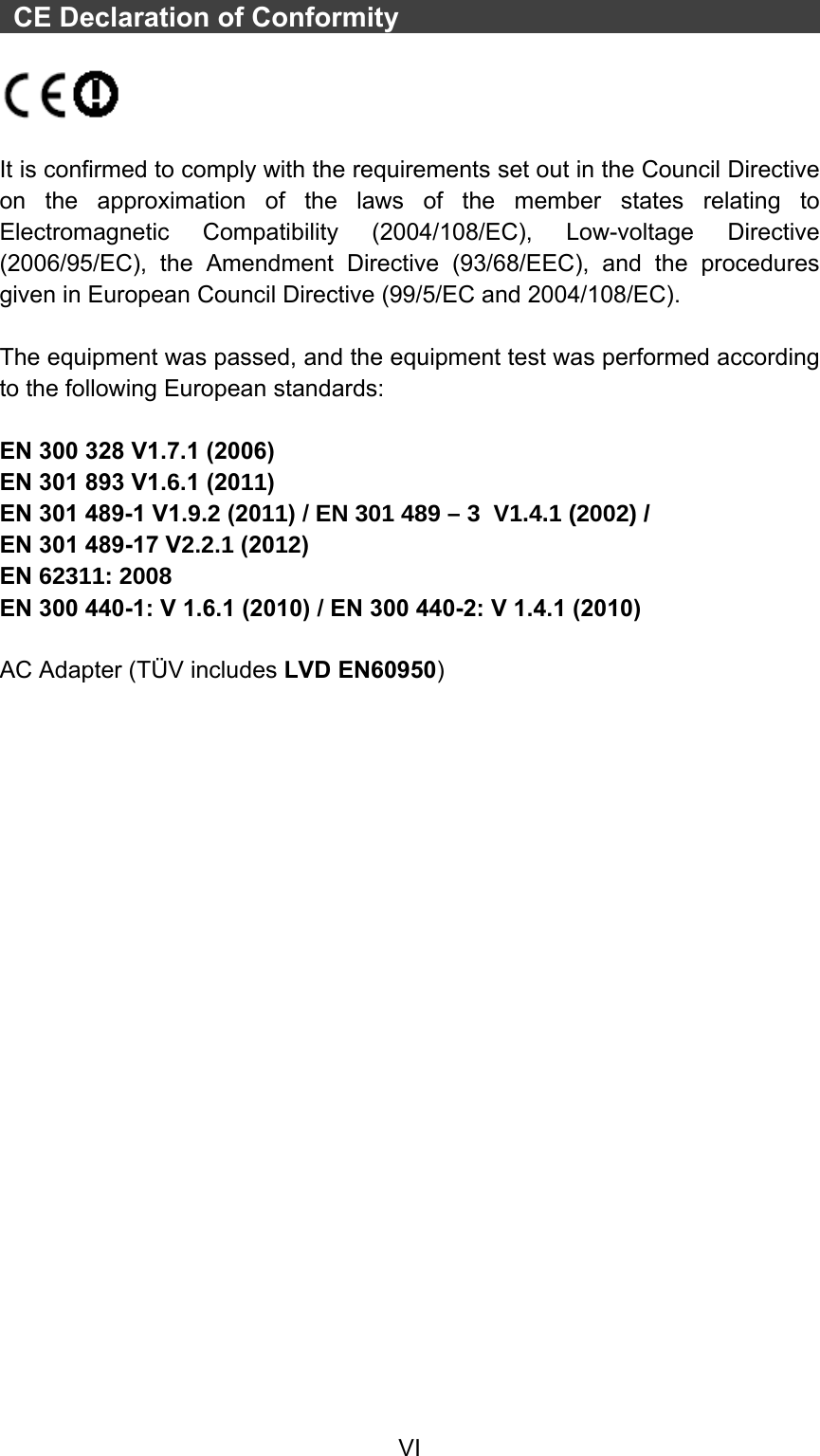


![Chapter Two - 12Operating Information Keyboard The keyboard is functionally equivalent to a full size desktop keyboard. A sample layout is shown below. You can use keyboard to adjust LCD backlight by pressing and holding [Fn] + [F3] to decrease the brightness or [Fn] + [F4] to increase the brightness. The Numeric Keypad The numeric keypad functions are the same as an electronic calculator. It is embedded in the main keyboard, with the numeric figures printed on the upper right of their respective keys. There are keys for the digits 0~9, the decimal point ( . ), addition ( + ), subtraction ( - ), multiplication ( * ), and division ( / ) in the keypad. To activate the keypad, press the Num Lock key. There are 15 keys switching from alphabetic to numeric. Press Num Lock again to return. Keyboard Backlight (Option) Press [Fn] + [F5] key for approximately 1 second to turn the keyboard backlight ON or OFF.](https://usermanual.wiki/MilDef-Crete/RK10/User-Guide-2170050-Page-25.png)
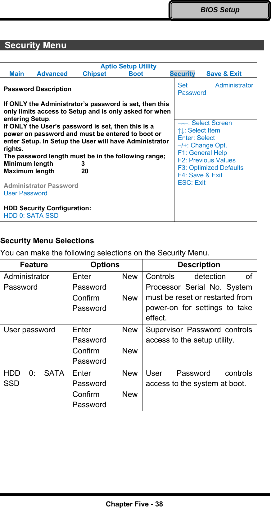
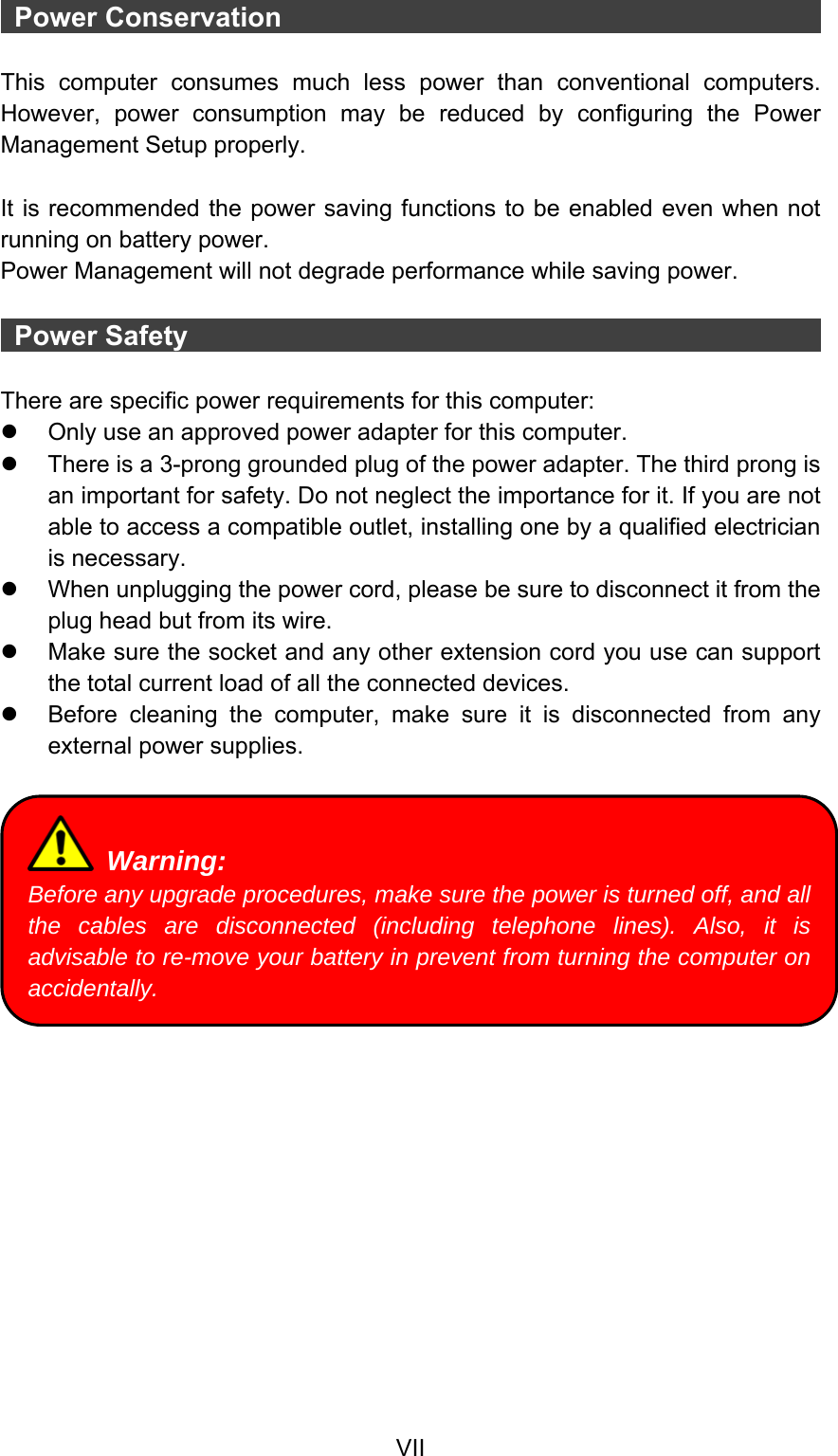
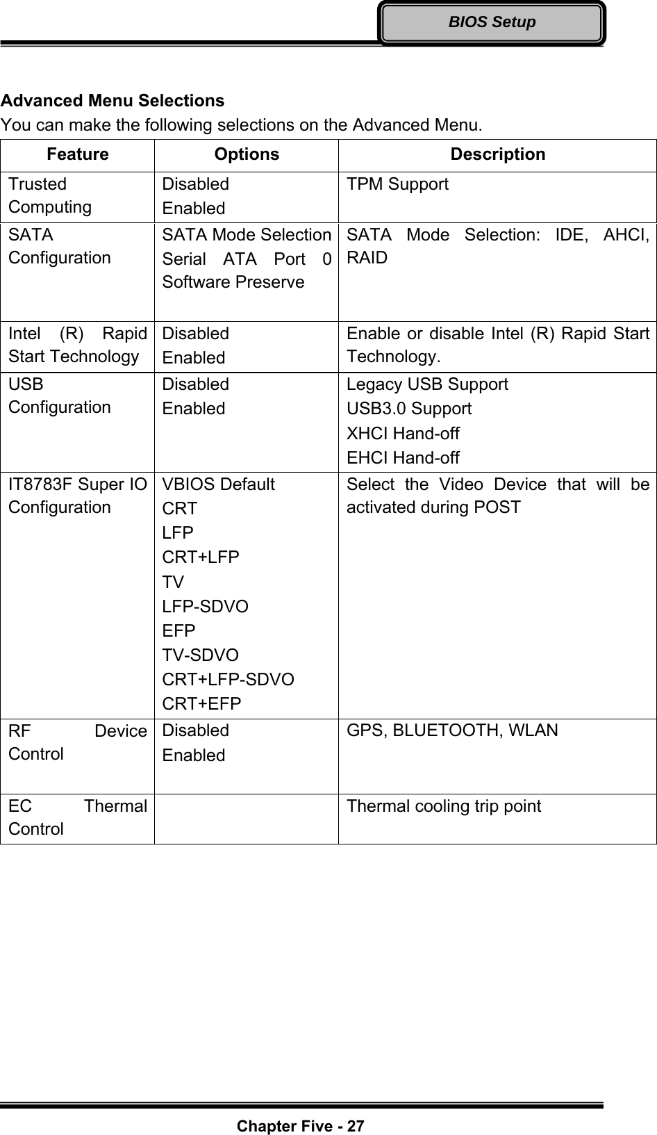
![Chapter Five - 25BIOS Setup Chapter Four - BIOS Setup Press [F2] at boot up to enter BIOS setup. Use arrow keys to select options and [+/-] to modify them. When finished, move to “Exit” and press [Enter] then confirm save by pressing [Y]. Main Menu Aptio Setup Utility Main Advanced Chipset Boot Security Save & Exit Choose the system default language BIOS Information BIOS Vendor Core Version Compliancy Project Version Build Date and Time EC Version System Language [English] System Date [Wed 06/19/2013] System Time [16:19:20] Access Level Administrator →←: Select Screen ↑↓: Select Item Enter: Select –/+: Change Opt. F1: General Help F2: Previous Values F3: Optimized Defaults F4: Save & Exit ESC: Exit Main Menu Selections You can make the following selections on the Main Menu. Use the sub-menus for other selections. Feature Options Description System Date MM/DD/YYYY Set the system date Month, Day, Year. System Time HH:MM:SS Set the system time Hour, Minute, Second. Note: ¾ The contents may vary depending on computer configurations. ¾ Incorrect settings may cause system malfunction. To correct it, restore the Optimized Defaults with F3.](https://usermanual.wiki/MilDef-Crete/RK10/User-Guide-2170050-Page-38.png)
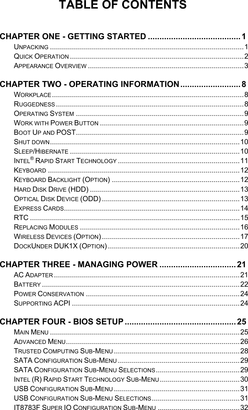
![Chapter Five - 28BIOS Setup Trusted Computing Sub-Menu Aptio Setup Utility Advanced Enables or Disables BIOS support for security device. O.S. will not show Security Device. TCG EFI protocol and INT1A interface will not be available. Configuration TPM SUPPORT [Disable] Current Status Information SUPPORT TURNED OFF →←: Select Screen ↑↓: Select Item Enter: Select –/+: Change Opt. F1: General Help F2: Previous Values F3: Optimized Defaults F4: Save & Exit ESC: Exit](https://usermanual.wiki/MilDef-Crete/RK10/User-Guide-2170050-Page-41.png)
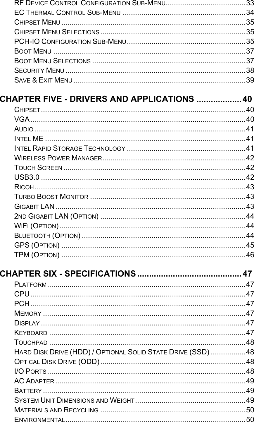
![Chapter Five - 29BIOS Setup SATA Configuration Sub-Menu Aptio Setup Utility Advanced Determine how SATA controller(s) operate. SATA Mode Selection [AHCI] Serial ATA Port 0 Empty Software Preserve Unknown Serial ATA Port 1 Empty Software Preserve Unknown Serial ATA Port 2 SATA SSD (120.0 Software Preserve SUPPORTED →←: Select Screen ↑↓: Select Item Enter: Select –/+: Change Opt. F1: General Help F2: Previous Values F3: Optimized Defaults F4: Save & Exit ESC: Exit SATA Configuration Sub-Menu Selections You can make the following selections on the SATA configuration sub-menu. Feature Options Description SATA Mode Selection IDE AHCI RAID Port 0 Disabled Enabled Enable or Disable SATA Port Hot Plug Disabled Enabled Designates this port as Hot Pluggable](https://usermanual.wiki/MilDef-Crete/RK10/User-Guide-2170050-Page-42.png)
![Chapter Five - 30BIOS Setup Intel (R) Rapid Start Technology Sub-Menu Aptio Setup Utility Advanced Enables or disable Intel (R) Rapid Start Technology Intel (R) Rapid Start Technology [Disabled] →←: Select Screen ↑↓: Select Item Enter: Select –/+: Change Opt. F1: General Help F2: Previous Values F3: Optimized Defaults F4: Save & Exit ESC: Exit](https://usermanual.wiki/MilDef-Crete/RK10/User-Guide-2170050-Page-43.png)
![Chapter Five - 31BIOS Setup USB Configuration Sub-Menu Aptio Setup Utility Advanced Enables Legacy USB support. AUTO option disables legacy support if no USB devices are connected. Disable option will keep USB devices available only for EFI applications USB Configuration USB Devices: 1 point Legacy USB Support [Enabled] USB3.0 Support [Enabled] XHCI Hand-off [Enabled] EHCI Hand-off [Disabled] →←: Select Screen ↑↓: Select Item Enter: Select –/+: Change Opt. F1: General Help F2: Previous Values F3: Optimized Defaults F4: Save & Exit ESC: Exit USB Configuration Sub-Menu Selections You can make the following selections on the USB configuration sub-menu. Feature Options Description Legacy USB enabled Disabled Enabled Enables Legacy USB support. AUTO option disables legacy support if no USB devices are connected. DISABLE option will keep USB devices available only for EFI applications. Usn3.0 Support Disabled Enabled Enable/Disable USB3.0 (XHCI) Controller support. XHCI Hand-off Disabled Enabled This is a workaround for OSes without XHCI hand-off support. This XHCI ownership change should be claimed by XHCI driver. EHCI Hand-off Disabled Enabled This is a workaround for OSes without EHCI hand-off support. This EHCI ownership change should be claimed by EHCI driver.](https://usermanual.wiki/MilDef-Crete/RK10/User-Guide-2170050-Page-44.png)
![Chapter Five - 33BIOS Setup RF Device Control Configuration Sub-Menu Aptio Setup Utility Advanced RF Device Control Setting RF Device Control GPS STATUS Present GPS [Enabled] BT STATUS Present BLUETOOTH [Enabled] WLAN STATUS Present WLAN [Enabled] →←: Select Screen ↑↓: Select Item Enter: Select –/+: Change Opt. F1: General Help F2: Previous Values F3: Optimized Defaults F4: Save & Exit ESC: Exit RF Device Control Configuration Sub-Menu Selections You can make the following selections on the RF Security Control sub-menu. Feature Options Description Wireless LAN Disabled Enabled Wireless Lan Control Enabled Wireless function GPS Disabled Enabled GPS Control Enabled GPS function BlueTooth Disabled Enabled BlueTooth Control Enabled Blue Tooth function](https://usermanual.wiki/MilDef-Crete/RK10/User-Guide-2170050-Page-46.png)
![Chapter Five - 34BIOS Setup EC Thermal Control Sub-Menu Aptio Setup Utility Advanced EC Thermal Control Setting EC Thermal Control Thermal cooling trip point [87 C] →←: Select Screen ↑↓: Select Item Enter: Select –/+: Change Opt. F1: General Help F2: Previous Values F3: Optimized Defaults F4: Save & Exit ESC: Exit](https://usermanual.wiki/MilDef-Crete/RK10/User-Guide-2170050-Page-47.png)
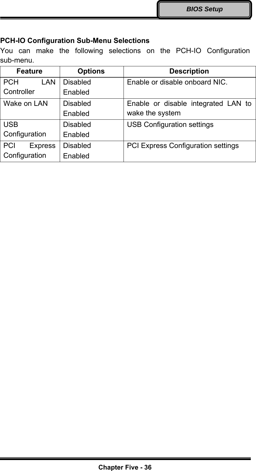
![Chapter Five - 35BIOS Setup Chipset Menu Aptio Setup Utility Main Advanced Chipset Boot Security Save & Exit System Agent (SA) Parameters ► System Agent (SA) Configuration ► PCH-IO Configuration →←: Select Screen ↑↓: Select Item Enter: Select –/+: Change Opt. F1: General Help F2: Previous Values F3: Optimized Defaults F4: Save & Exit ESC: Exit Chipset Menu Selections You can make the following selections on the Chipset sub-menu. Feature Options Description System Agent (SA) Configuration System Agent (SA) Parameters PCH-IO Configuration PCH Parameter PCH-IO Configuration Sub-Menu Aptio Setup Utility Chipset Enable or disable onboard NIC. Intel PCH RC Version 1.2.2.0 Intel PCH SKU Name QM67 Intel PCH Rev ID 05/B3 PCH LAN Controller [Enabled] Wake on LAN [Enabled] ► USB Configuration ► PCI Express Configuration →←: Select Screen ↑↓: Select Item Enter: Select –/+: Change Opt. F1: General Help F2: Previous Values F3: Optimized Defaults F4: Save & Exit ESC: Exit](https://usermanual.wiki/MilDef-Crete/RK10/User-Guide-2170050-Page-48.png)
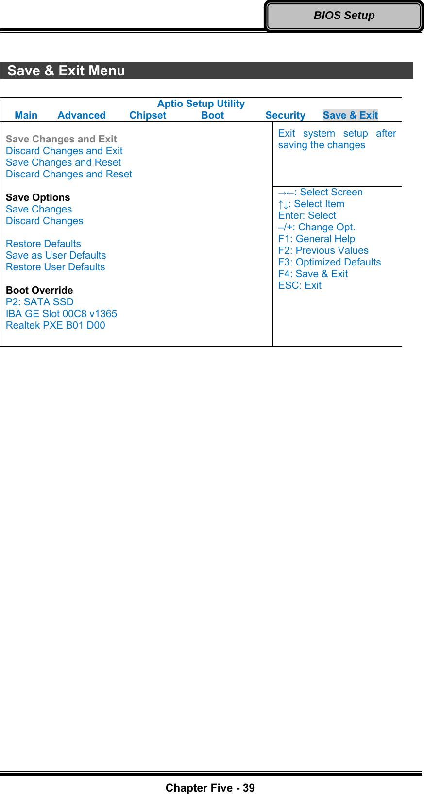
![Chapter Five - 37BIOS Setup Boot Menu Aptio Setup Utility Main Advanced Chipset Boot Security Save & Exit Sets the system boot order Boot Option Priorities Boot Option #1 [P2: SATA SSD...] Boot Option #2 [IBA GE Slot 00C8 v...] Network Device BBS Priorities Hard Driver BBS Priorities →←: Select Screen ↑↓: Select Item Enter: Select –/+: Change Opt. F1: General Help F2: Previous Values F3: Optimized Defaults F4: Save & Exit ESC: Exit The system will try to boot from device on top then the 2nd and so on. If there is more than one device in each category, only the device on top of sub-menu can boot up. Boot Menu Selections You can make the following selections on the Boot menu. Feature Options Description Boot Option #1 Sets the system boot order Boot Option #2 Sets the system boot order Network Device BBS Priorities Set the order of the legacy devices in this group Hard Drive BBS Priorities Set the order of the legacy devices in this group](https://usermanual.wiki/MilDef-Crete/RK10/User-Guide-2170050-Page-50.png)