MilDef Crete RK786EX Notebook Computer User Manual RK786 EX
MilDef Crete Inc. Notebook Computer RK786 EX
UserManual.wiki
>
MilDef Crete
>
RK786EX User Manual
Users Manual
Navigation menu
Upload a User Manual
Namespaces
Wiki Guide
HTML
PDF
Info
Views
User Manual
Discussion / Help
Navigation
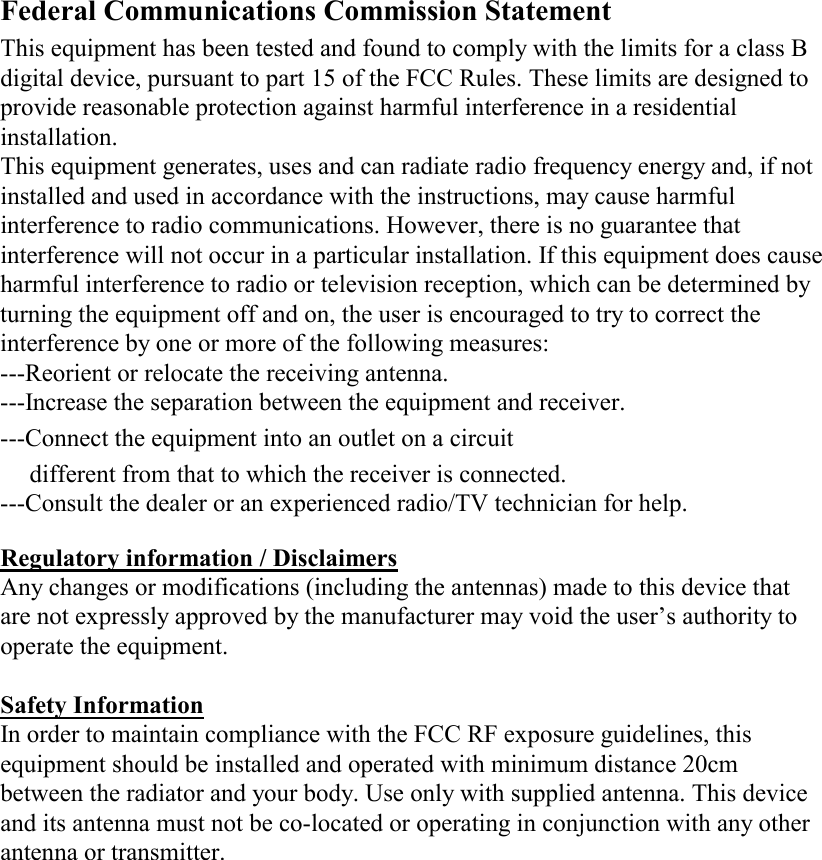
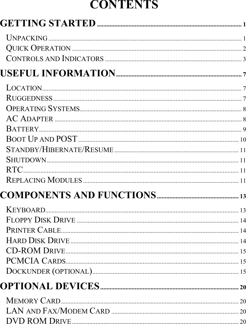
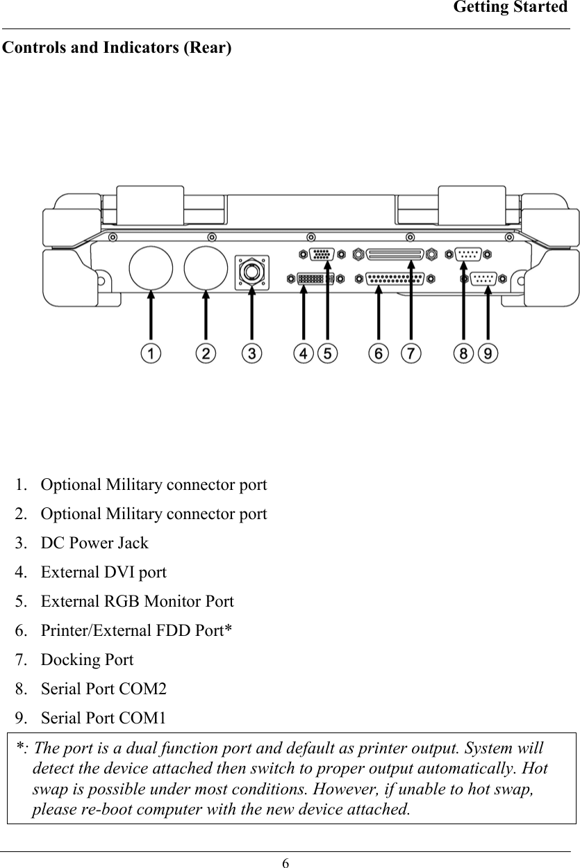
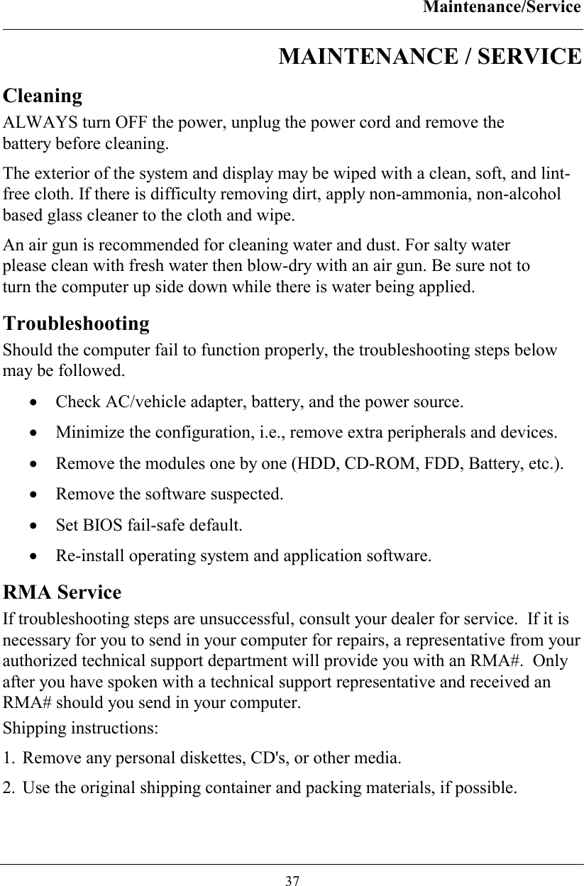
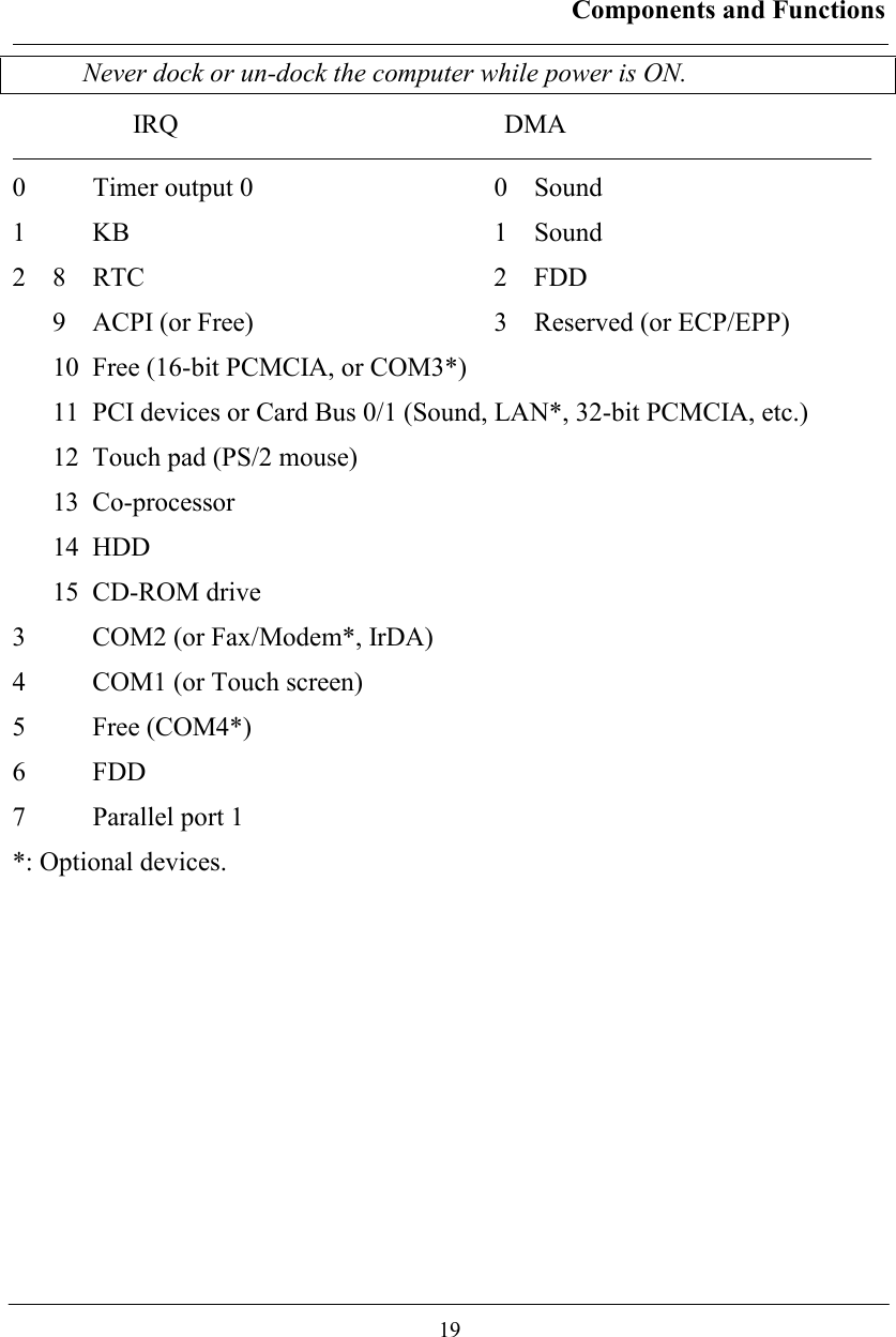
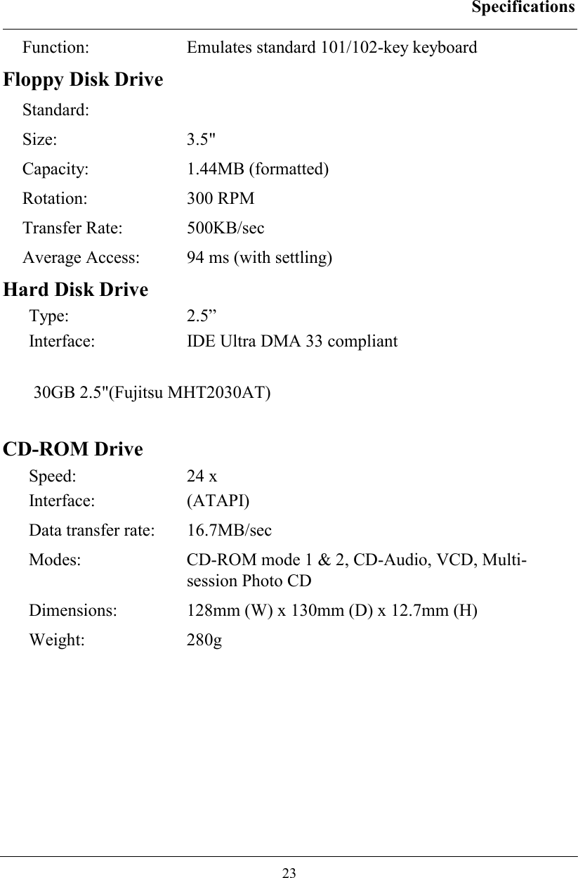
![Components and Functions 14 Keyboard Backlight (optional) Press [Fn] [F5] key for approximately 1 second turns keyboard backlight ON or OFF. Floppy Disk Drive The computer comes with a 3.5" 1.44MB floppy disk drive (FDD). The 1.44MB FDD can also read and write 720KB double side double density diskette. It is recommended that high density (2HD marking) diskette been used only. FDD can be removed and swapped with CD-ROM drive .When CD-ROM drive is installed, you may still use FDD by connecting it via the rear DB-25 port. Printer Cable For most printers there is no special requirement in connection. However, some printer cables do not contain all 25 wires. To avoid malfunction, the printer adapter cable comes with your computer should be attached to the printer cable. The purpose is to re-connect all the ground pins. Devices equivalent to printer such as scanner, Laplink cable, etc. also need this cable. Please note do not use the FDD cable as printer adapter cable. Hard Disk Drive The Hard Disk Drive (HDD) is a 2.5” type standard IDE interface data storage device. HDD and FDD, CD-ROM drives are removable. This provides convenience and security. They can ONLY be removed while the power is OFF.](https://usermanual.wiki/MilDef-Crete/RK786EX/User-Guide-486624-Page-23.png)
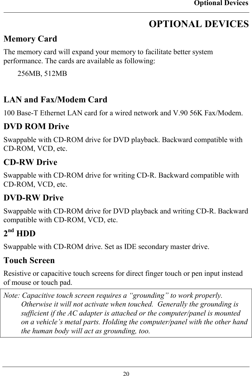
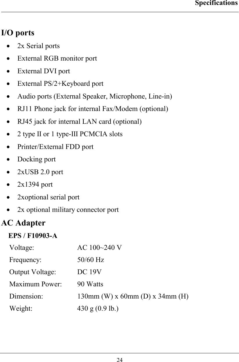
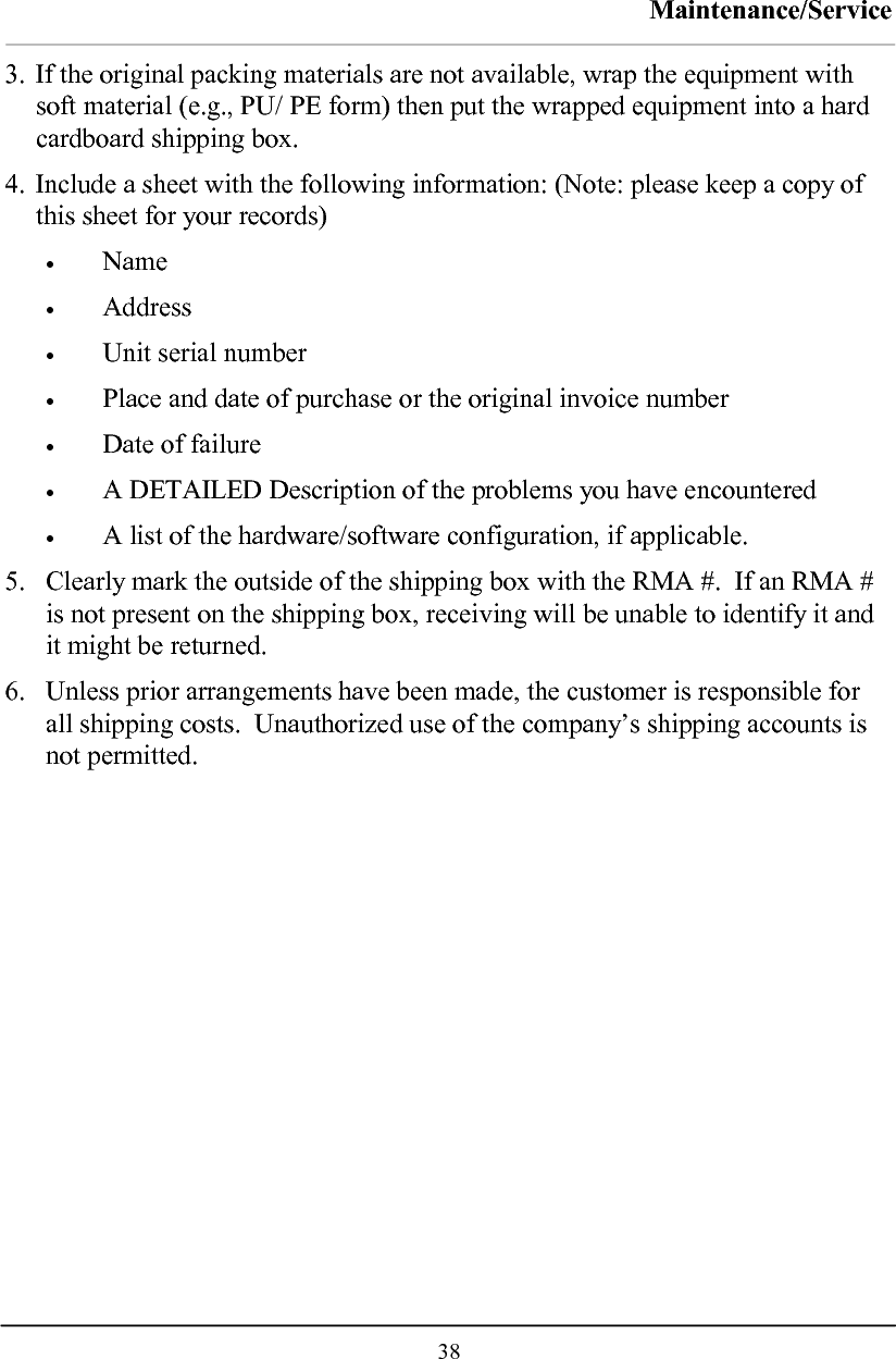
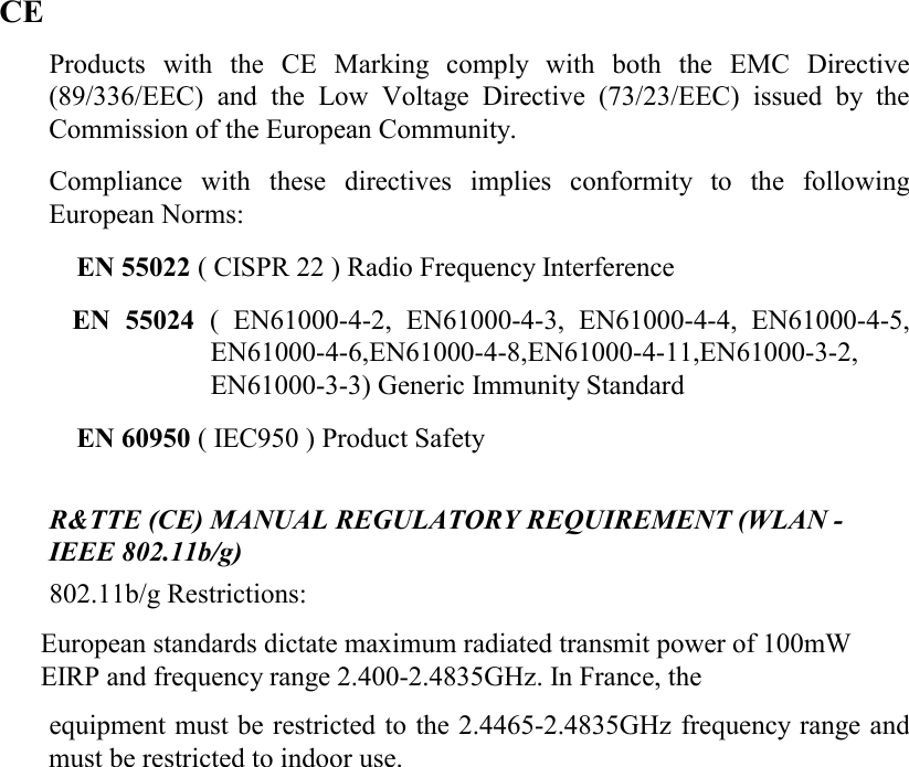
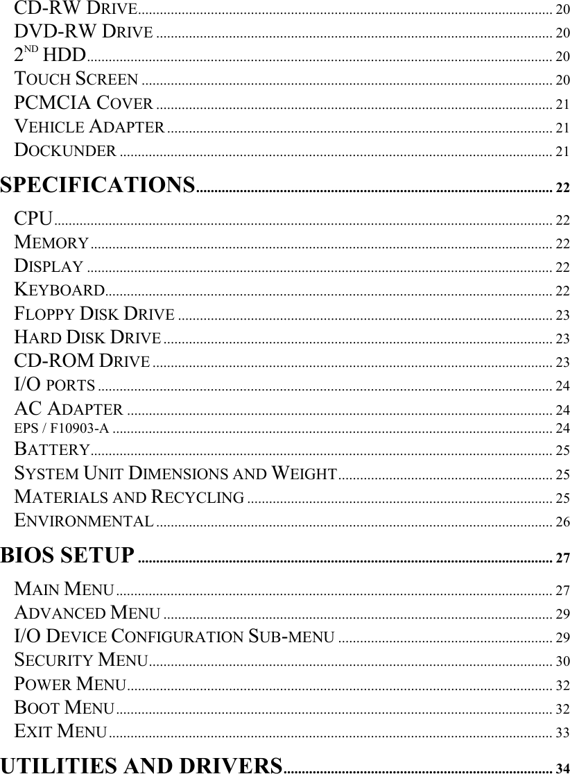
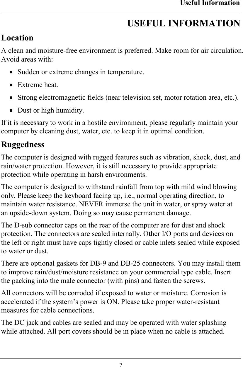
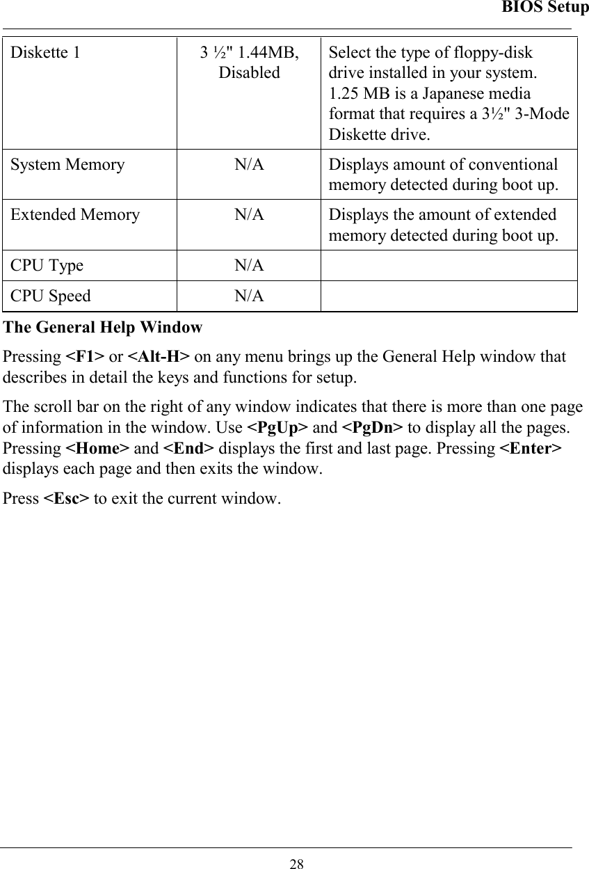
![BIOS Setup 27 BIOS SETUP Press [F2] at boot up to enter BIOS setup. Use arrow keys to select options and [+/-] to modify them. When finished, move to ”Exit” and press [Enter] then confirm save by pressing [Y]. Main Menu Phoenix BIOS Setup Utility Main Advanced Security Power Boot Exit Item Specific Help System Time [16:19:20] System Date: [03/02/2003] Legacy Diskette A: [1.44/1.25MB3½”] Primary Master [30006MB] Secondary Master [CD-ROM] System Memory: 640 KB Extended Memory: 522752 KB CPU Type Mobile Intel® Pentium® M CPU Speed 1400 MHz <Tab>, <Shift-Tab>, or <Enter> selects field F1 Help ↑↓ Select Item -/+ Change Values F9 Setup Defaults Esc Exit ← Select Menu Enter Select ► Sub-Menu F10 Save and Exit Note: The contents may vary depending on computer configurations. Main Menu Selections You can make the following selections on the Main Menu. Use the sub menus for other selections. Feature Options Description System Time HH:MM:SS Set the system time Hour, Minute, Second. System Date MM/DD/YYYY Set the system date Month, Day, Year.](https://usermanual.wiki/MilDef-Crete/RK786EX/User-Guide-486624-Page-36.png)
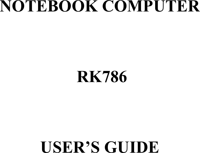
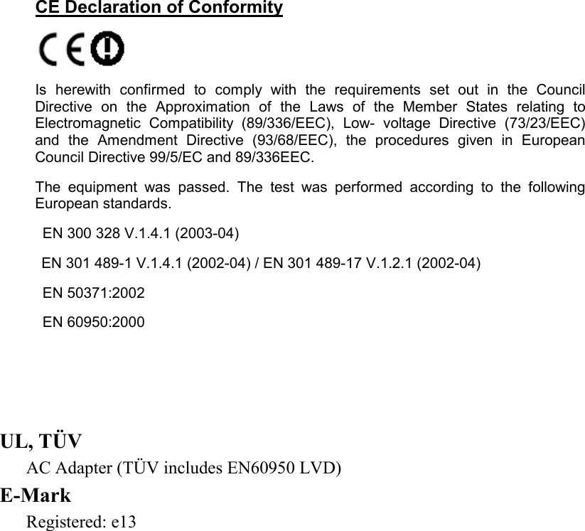
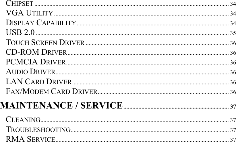
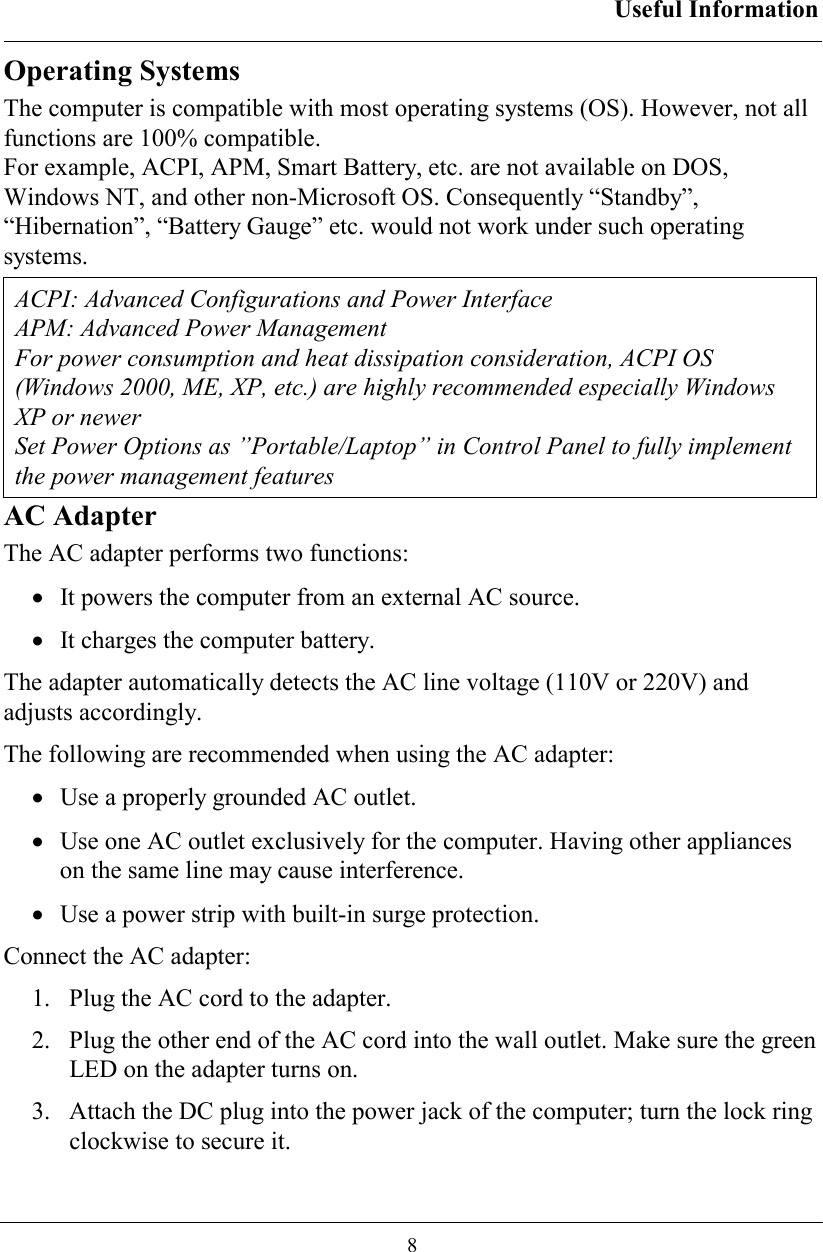
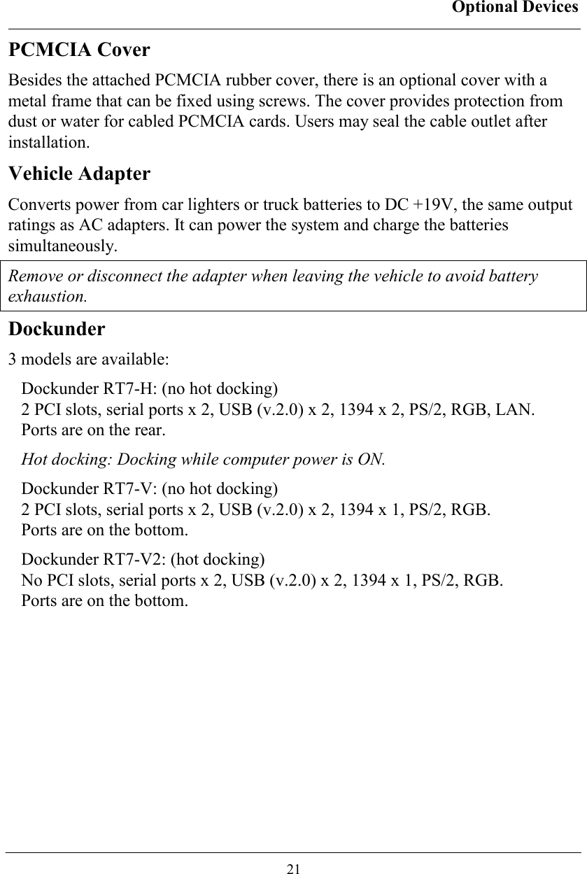
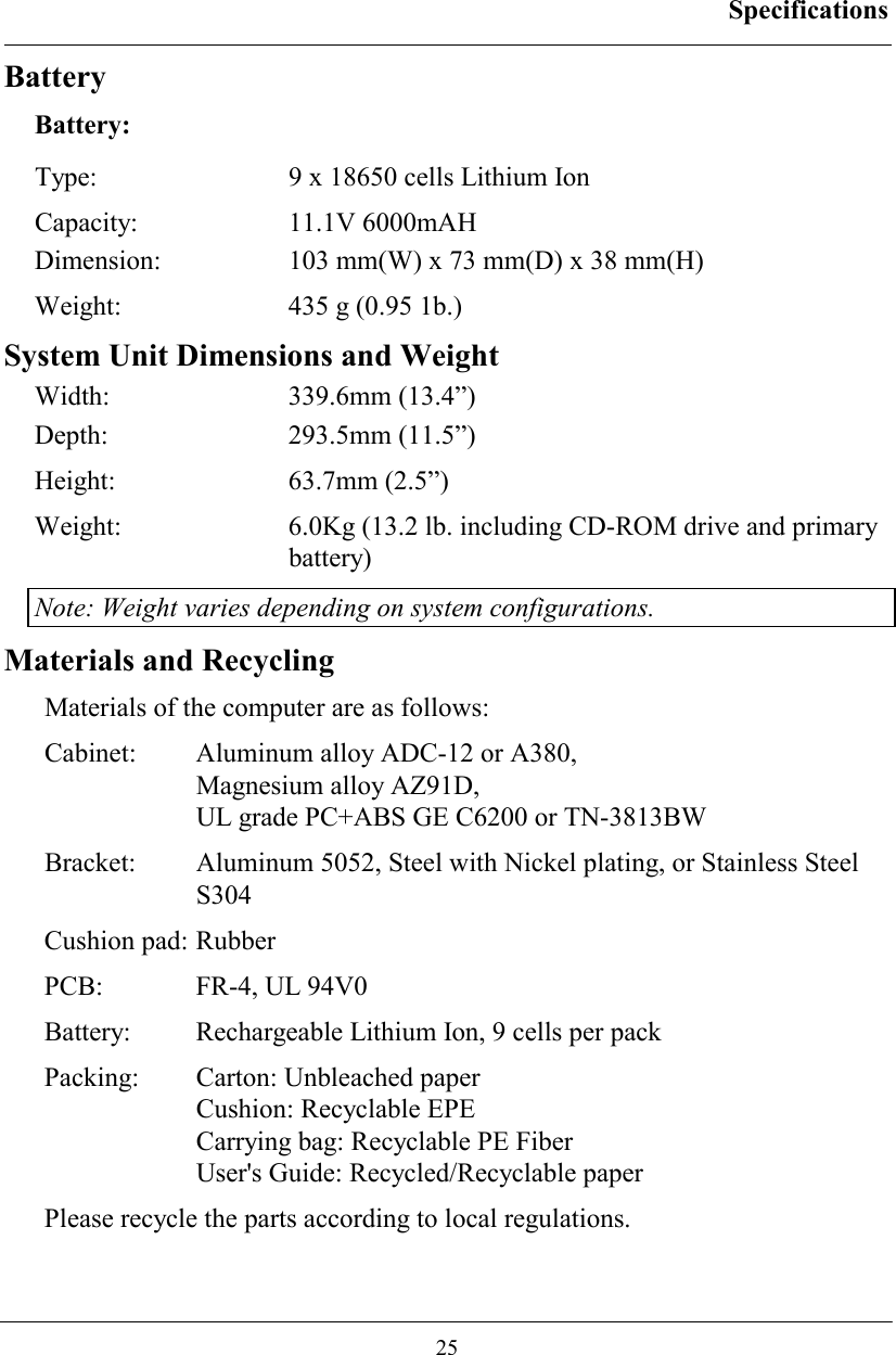
![BIOS Setup 29 Advanced Menu Phoenix BIOS Setup Utility Main Advanced Security Power Boot Exit Item Specific Help Boot-time Diagnostic Screen: [Enabled] Summary Screen: [Disabled] Legacy USB Support: [Enabled] POST Memory Test: [Quick Test] BootUp Display: [CRT+LCD] I/O Device Configuration Peripheral Configuration for COM port Parallel port F1 Help ↑↓ Select Item -/+ Change Values F9 Setup Defaults Esc Exit ← Select Menu Enter Select ► Sub-Menu F10 Save and Exit Warning: Incorrect settings may cause system malfunction. To correct it, restore the Setup Defaults with <F9>. Advanced Menu Selections It is usually not necessary for user to set up parameters here. Only technician may need to change the settings for diagnostic purposes. For most frequently altered setup “I/O Device Configuration” please refer following: I/O Device Configuration Sub-menu Phoenix BIOS Setup Utility Advanced I/O Device Configuration Item Specific Help COM1 port: [Enabled] COM1 mode: [COM1] Base I/O address/IRQ: [3F8/IRQ 4] COM2 port: [Enabled] COM2 Mode: [COM2] IrDA Mode: [Disabled] Base I/O address/IRQ: [2F8/IRQ 3] COM3 port: [3E8/IRQ 10] COM4 port: [2E8/IRQ 5] Configure COM1 device options [COM1]: External device [TTL1]: Internal device](https://usermanual.wiki/MilDef-Crete/RK786EX/User-Guide-486624-Page-38.png)
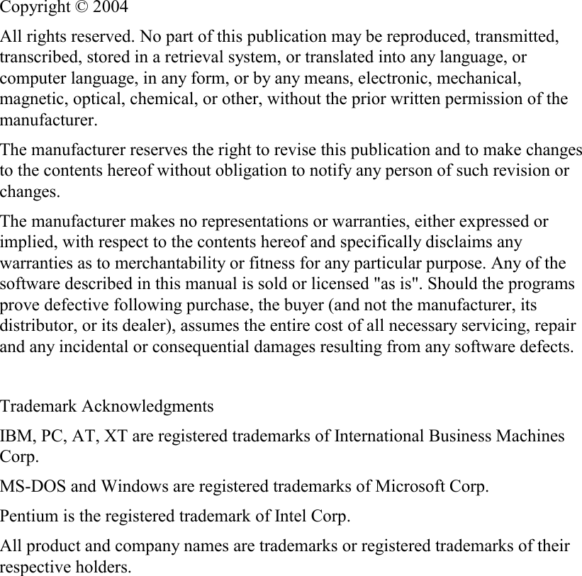
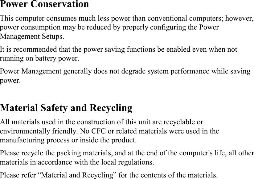
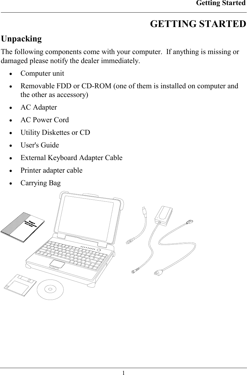
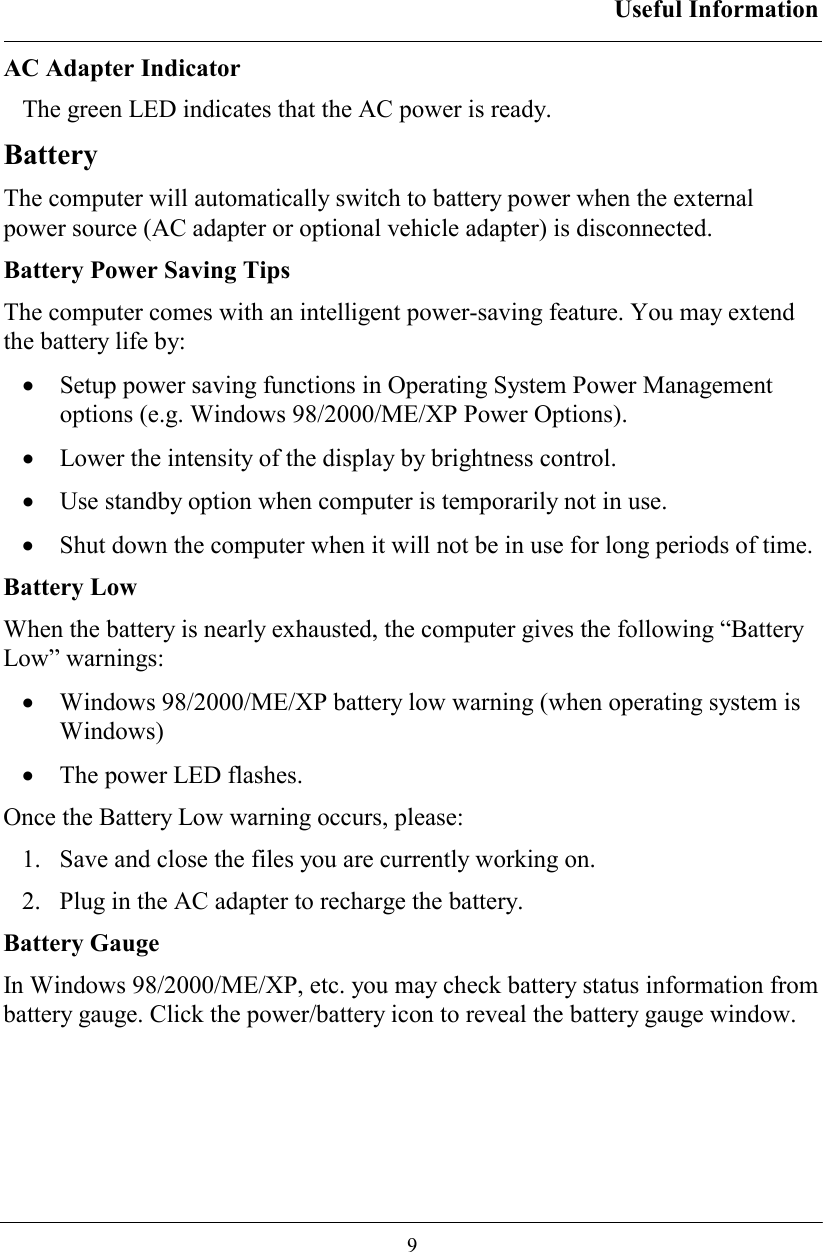
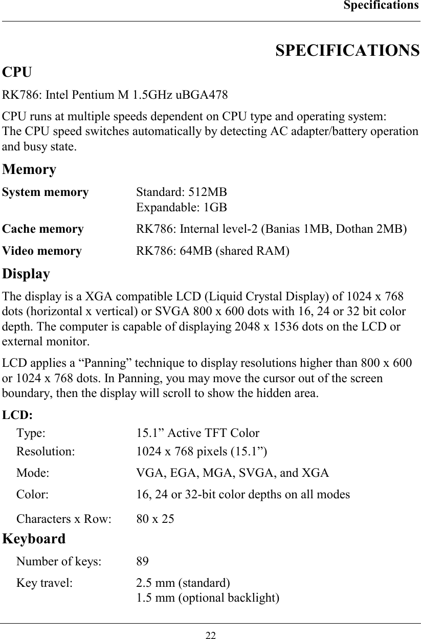
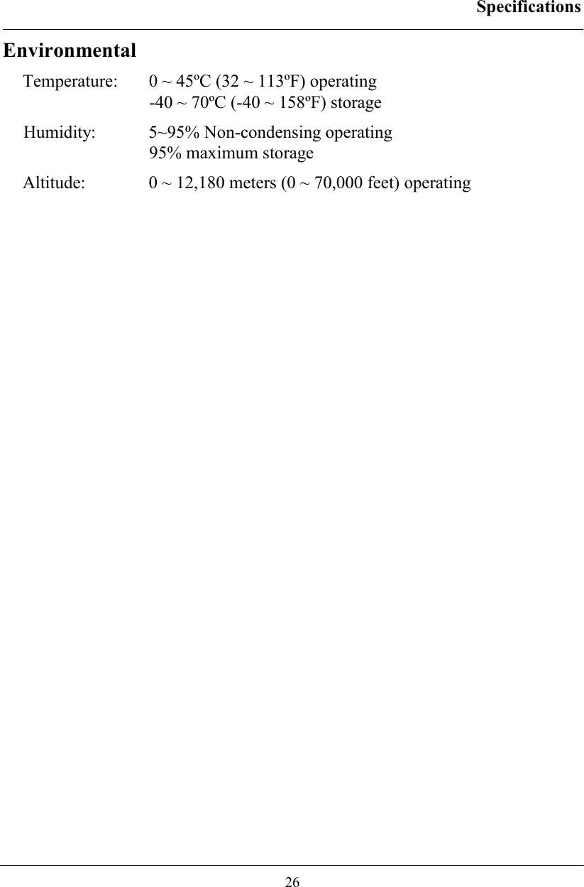
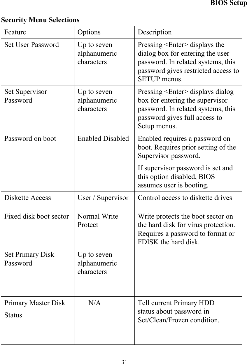
![BIOS Setup 30 Parallel Port: [Enabled] Mode: [Output Only] Base I/O address: [378] Interrupt [IRQ 7] F1 Help ↑↓ Select Item -/+ Change Values F9 Setup Defaults Esc Exit ← Select Menu Enter Select ► Sub-Menu F10 Save and Exit I/O Device Configuration Sub-menu Selections Please refer the on screen help for selections. BIOS shows COM3, COM4 but they are optional devices. Only when COM3/4 card is installed the function exists. Security Menu Warning: If you forget user/supervisor password, the computer has to send back to manufacturer and replace EEPROM to make it work again. For loss of HDD password, both the HDD and its contents cannot be recovered. Phoenix BIOS Setup Utility Main Advanced Security Power Boot Exit Item Specific Help Set Supervisor Password: [Enter] Set User Password: [Enter] Password on boot: [Disabled] Fixed disk boot sector: [Normal] Diskette access: [Normal] Set Primary Disk Password: [Enter] Primary Master Disk Status [HDD Paswrd Clean] Supervisor password controls access to the setup utility. F1 Help ↑↓ Select Item -/+ Change Values F9 Setup Defaults Esc Exit ← Select Menu Enter Select ► Sub-Menu F10 Save and Exit](https://usermanual.wiki/MilDef-Crete/RK786EX/User-Guide-486624-Page-39.png)
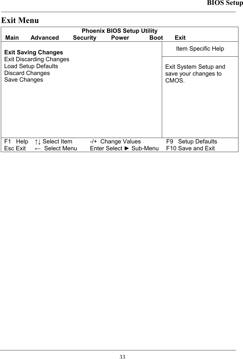
![BIOS Setup 32 Power Menu Phoenix BIOS Setup Utility Main Advanced Security Power Boot Exit Item Specific Help Power Button Function: [Power Off] Lid Close Function: [LCD Off] Sleep Button Function: [Stand By] Speed Step Technology: [GV3] Select LID close function as LCD Off or Standby function F1 Help ↑↓ Select Item -/+ Change Values F9 Setup Defaults Esc Exit ← Select Menu Enter Select ► Sub-Menu F10 Save and Exit Boot Menu Phoenix BIOS Setup Utility Main Advanced Security Power Boot Exit Item Specific Help +Removable Devices +Hard Drive CD-ROM Drive Network Boot Press ↑ or ↓ to select device. Press + to move the selected device up or – to move down. Press [Enter] to show sub-menu selections. [Shift+1] enable or disable a device. F1 Help ↑↓ Select Item -/+ Change Values F9 Setup Defaults Esc Exit ← Select Menu Enter Select ► Sub-Menu F10 Save and Exit The system will try boot from device on top then the 2nd and so on. If there are more than one device in each category, only the device on top of sub-menu can boot up.](https://usermanual.wiki/MilDef-Crete/RK786EX/User-Guide-486624-Page-41.png)