MilDef Crete RK9 15" NOTEBOOK COMPUTER User Manual
MilDef Crete Inc. 15" NOTEBOOK COMPUTER
UserManual.wiki
>
MilDef Crete
>
RK9 User Manual
Users Manual
Navigation menu
Upload a User Manual
Namespaces
Wiki Guide
HTML
PDF
Info
Views
User Manual
Discussion / Help
Navigation
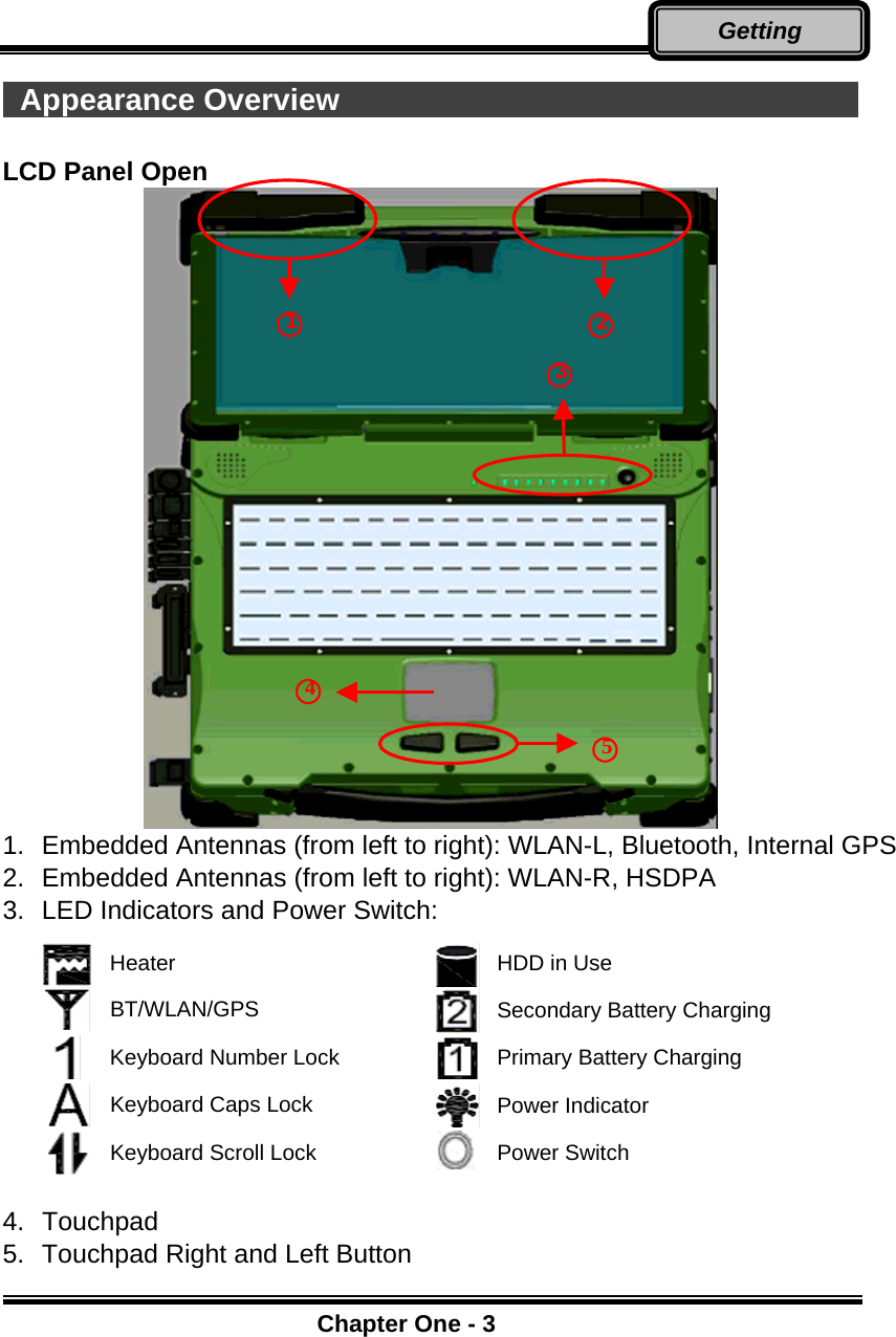
![Chapter Two - 12Operating Keyboard Backlight (Optional) Press [Fn] [F5] key for approximately 1 second to turn the keyboard backlight ON or OFF. Hard Disk Drive (HDD) The Hard Disk Drive (HDD) is a 2.5” type/ 9.5mm height standard SATA interface data storage device. HDD and ODD (Optical Disk Drive) are removable. This design provides convenience and security. They can ONLY be removed when the power is OFF. ODD (Optical Disk Device) There is a 5.25” type/ 12.7mm height standard SATA interface ODD. The actual device will depend on the model you purchased. The ODD may be used as a boot device if properly set in the BIOS. The ODD accepts a variety of standard 12cm CDs, DVD-ROM (Single Layer, Dual Layer), DVD-Video, DVD-R*10 (1.4 GB, 2.8 GB, 4.7GB), DVD-RW (Ver.1.1/1.2 1.4 GB, 2.8 GB, 4.7 GB, 9.4 GB), DVD-R DL (8.5 GB), DVD-RAM (1.4 GB, 2.8 GB, 4.7 GB, 9.4 GB), +R (4.7 GB), +R DL (8.5 GB), +RW (4.7 GB), CD-Audio, CD-ROM (XA compatible), CD-R, Photo CD (multiple session compatible), Video CD, CD EXTRA, CD-RW, CD-TEXT and etc. Do not use the IDE-interface ODD; it may cause the Note: NEVER drop your HDD, ODD or expose them to high temperature,high humidity, or any hazardous environment. NEVER try todisassemble the module. Static discharge may destroy your deviceand data. Always pick up the modules by touching the case only.](https://usermanual.wiki/MilDef-Crete/RK9/User-Guide-1399977-Page-25.png)