MilDef Crete RT886EX Notebook Computer User Manual
MilDef Crete Inc. Notebook Computer
UserManual.wiki
>
MilDef Crete
>
RT886EX User Manual
User manual
Navigation menu
Upload a User Manual
Namespaces
Wiki Guide
HTML
PDF
Info
Views
User Manual
Discussion / Help
Navigation

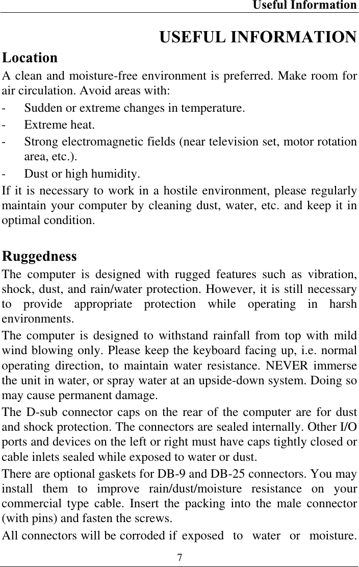
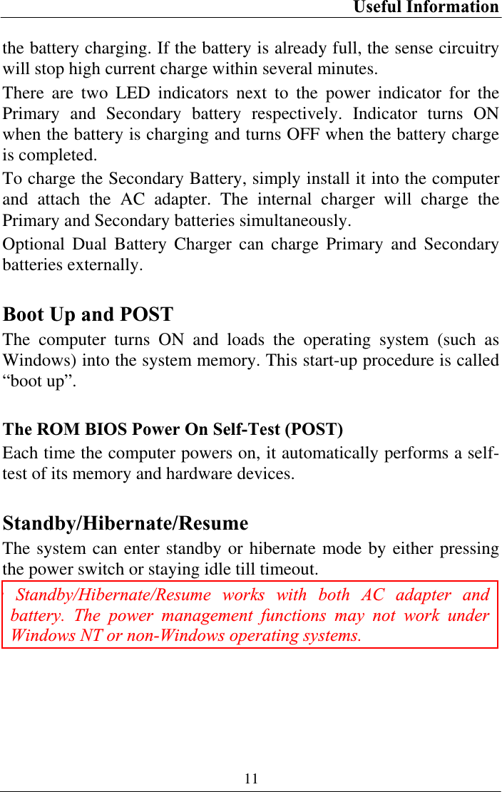
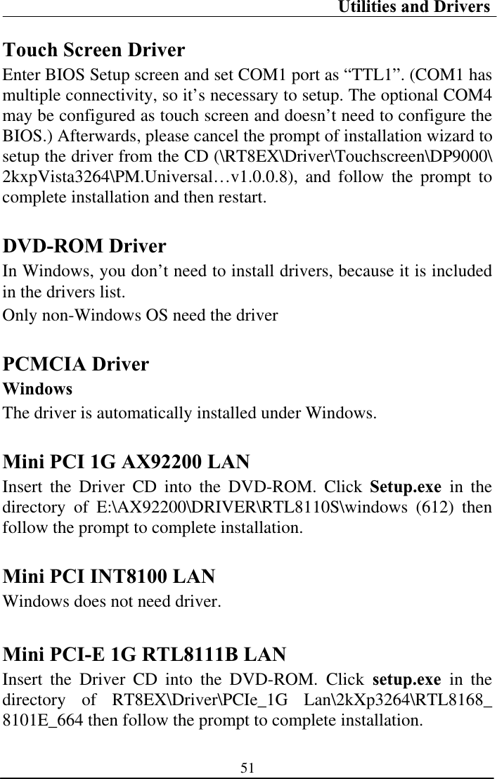
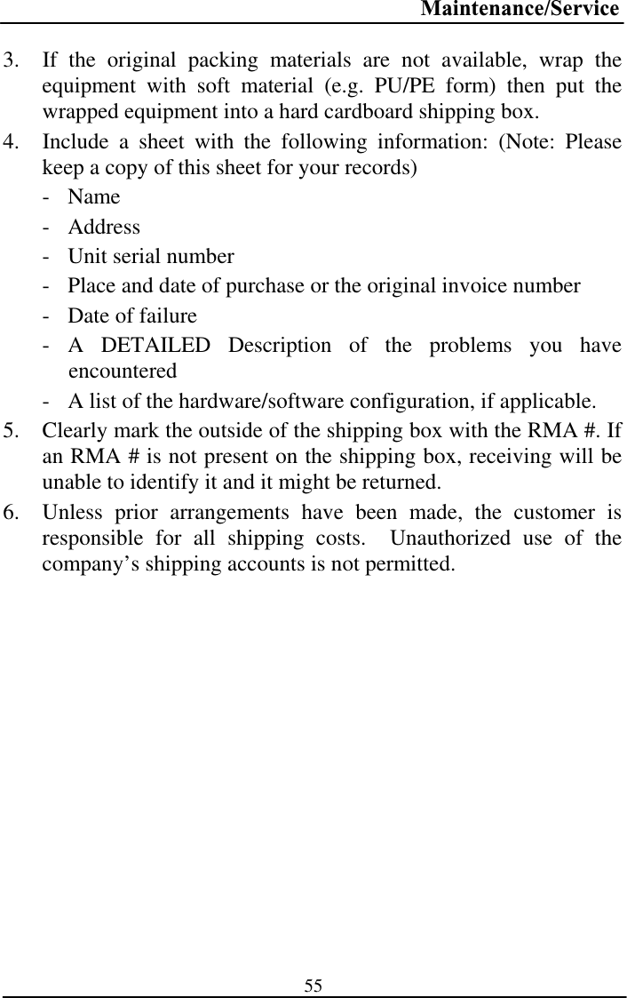
![Components and Functions 16Keyboard Backlight (optional) Press [Fn] [F5] key for approximately 1 second turns keyboard backlight ON or OFF. Printer Cable For most printers there is no special requirement in connection. However, some printer cables do not contain all 25 wires. To avoid malfunction, the printer adapter cable comes with your computer should be attached to the printer cable. The purpose is to re-connect all the ground pins. Devices equivalent to printer such as scanner, Lap link cable, etc. also need this cable. Hard Disk Drive The Hard Disk Drive (HDD) is a 2.5” type standard SATA interface data storage device. HDD and DVD-ROM drives are removable. This provides convenience and security. They can ONLY be removed while the power is OFF. Note: NEVER drop your HDD, DVD-ROM module or expose them to high temperature, high humidity, or any hazardous environment. NEVER try to disassemble the module.Static discharge may destroy your device and data. Always pick up the modules by touching the case only.](https://usermanual.wiki/MilDef-Crete/RT886EX/User-Guide-1168665-Page-26.png)
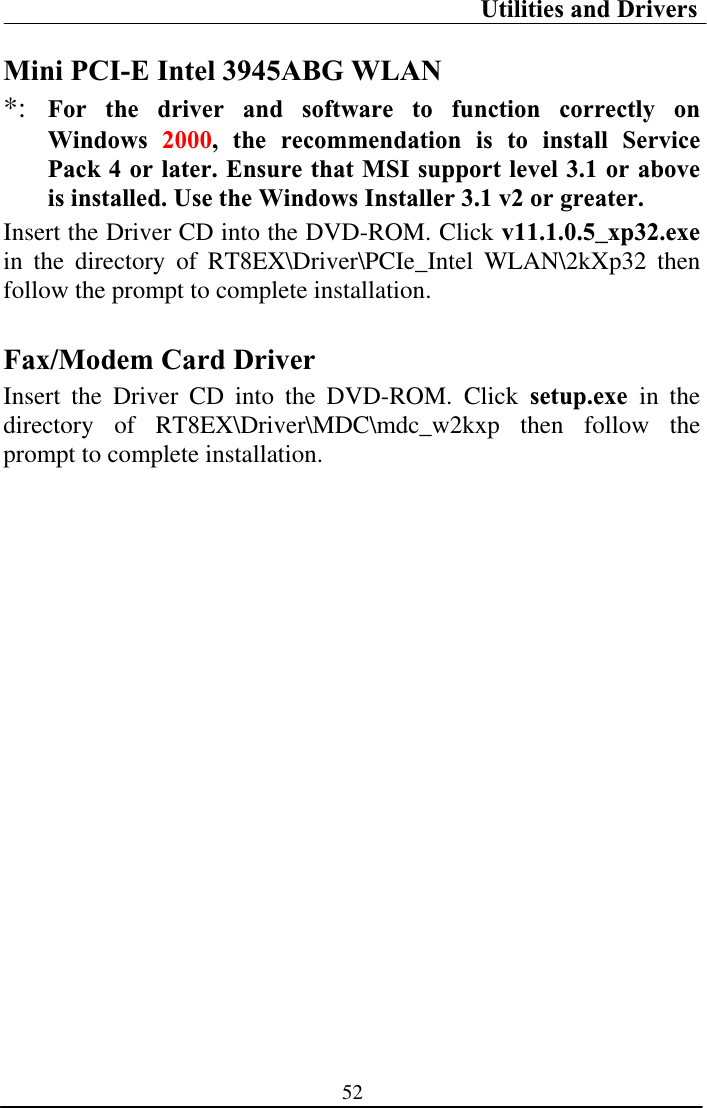
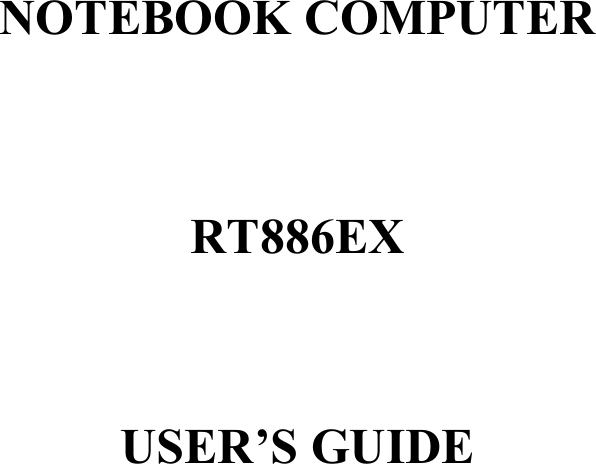
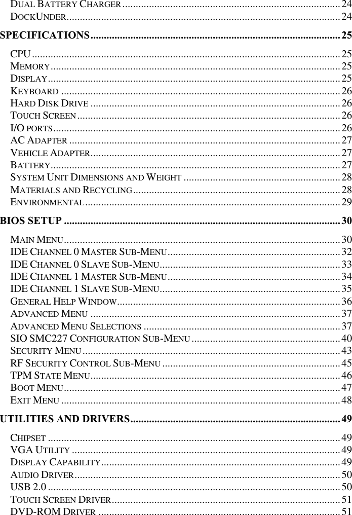
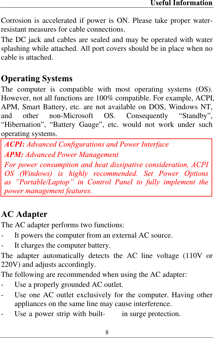
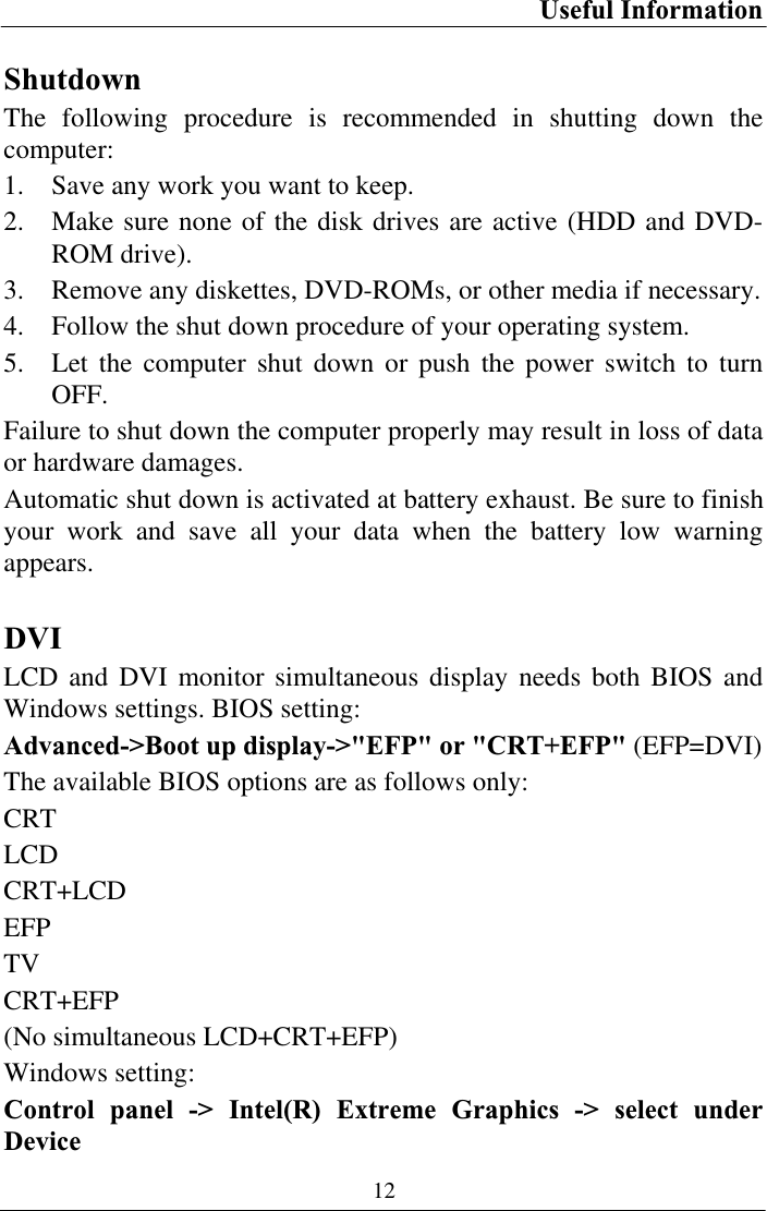
![BIOS Setup 30BIOS SETUP Press [F2] at boot up to enter BIOS setup. Use arrow keys to select options and [+/-] to modify them. When finished, move to ”Exit” and press [Enter] then confirm save by pressing [Y].Main Menu Phoenix TrustedCore (tm) Setup Utility Main Advanced Security TPM State Boot ExitItem Specific Help System Time: [16:19:20] System Date: [03/02/2007] Legacy Diskette A: [1.44/1.25MB 3½"] • IDE Channel 0 Master [None] • IDE Channel 0 Slave [None] • IDE Channel 1 Master [None] • IDE Channel 1 Slave [None]System Memory: 640 KB Extended Memory: 1038336 KB <Tab>, <Shift-Tab>, or <Enter> selects field. F1 Help ĹĻ Select Item –/+ Change Values F9 Setup Defaults Esc Exit ļ Menu Enter Select Ź Sub-Menu F10 Save and Exit Note: The contents may vary depending on computer configurations. Main Menu Selections You can make the following selections on the Main Menu. Use the sub-menus for other selections. Feature Options Description System Time HH:MM:SS Set the system time Hour, Minute, Second.System Date MM/DD/YYYY Set the system date Month, Day, Year.](https://usermanual.wiki/MilDef-Crete/RT886EX/User-Guide-1168665-Page-40.png)
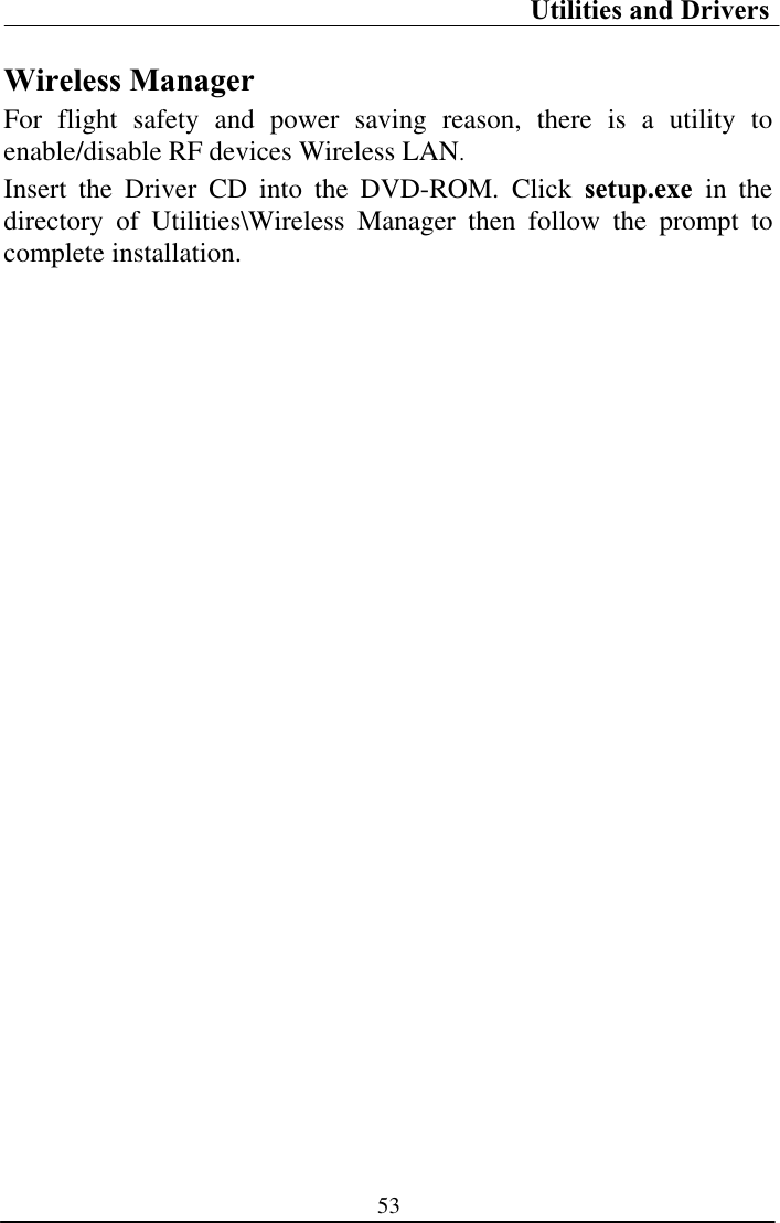
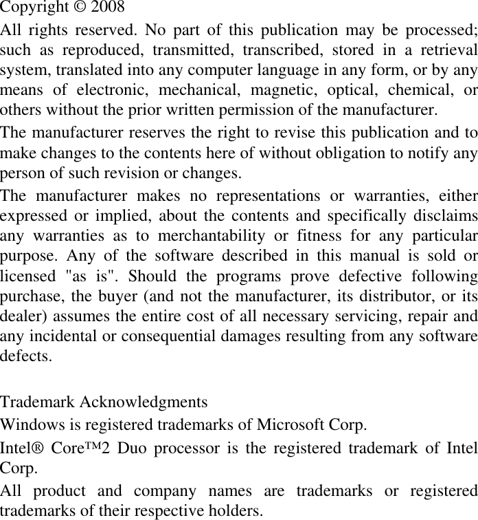
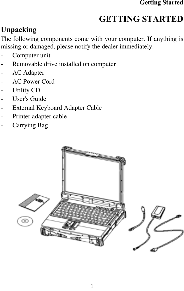
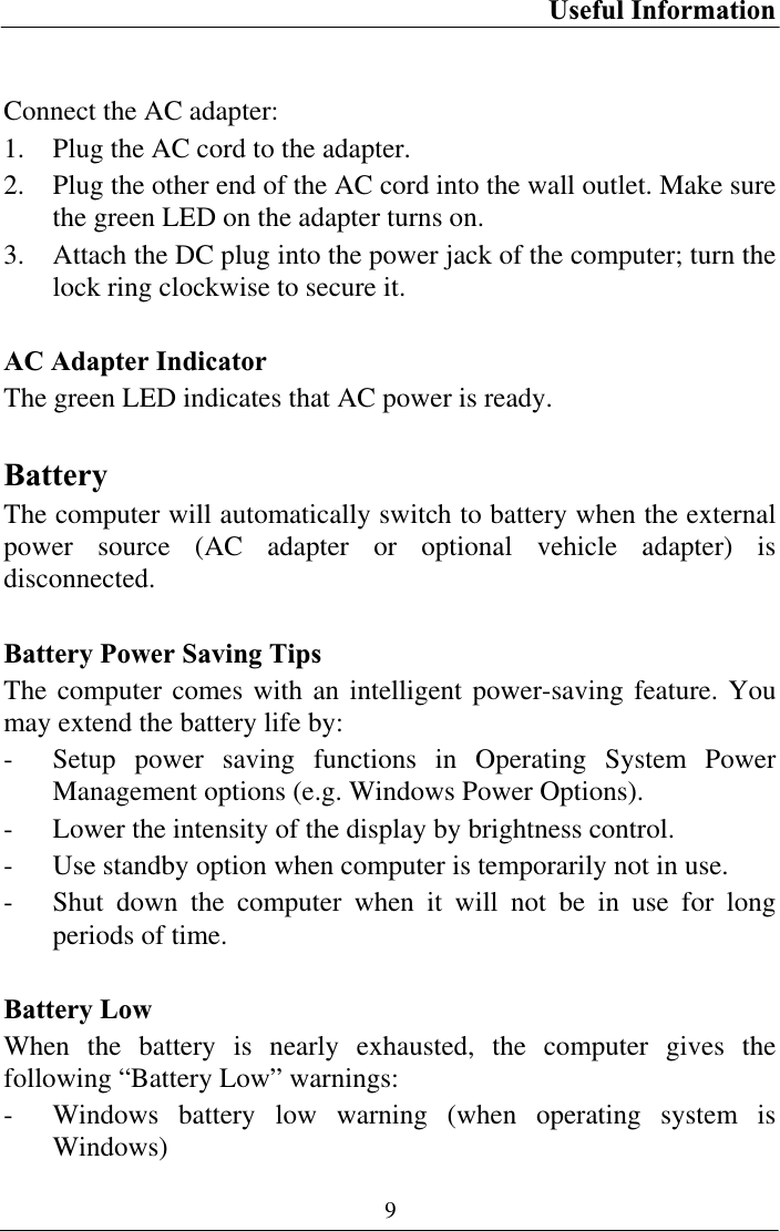
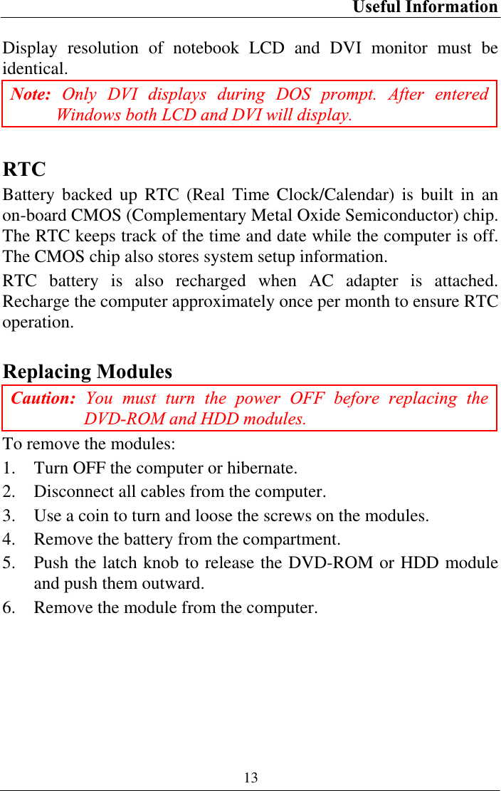
![BIOS Setup 32IDE Channel 0 Master Sub-Menu Phoenix TrustedCore (tm) Setup Utility MainIDE Channel 0 Master [None] Item Specific Help Type: [Auto] LBA Format Total Sectors: 78140160 Maximum Capacity: 40008MB SATA1Multi-Sector Transfers: [Disabled] LBA Mode Control: [Disabled] 32 Bit I/O: [Disabled] Transfer Mode: [Standard] Ultra DMA Mode: [Disabled] User = you enter parameters of hard-disk drive installed at this connection.Auto = autotypes hard-disk drive installed here. CD-ROM = a CD-ROM drive is installed here. ATAPI Removable = removable disk drive is installed here. F1 Help ĹĻ Select Item –/+ Change Values F9 Setup Defaults Esc Exit ļ Menu Enter Select Ź Sub-Menu F10 Save and ExitIDE Channel 0 Master Sub-Menu Selections You can make the following selections on the IDE Channel 0 Master Sub-Menu.Feature Options Description Type User AutoCD-ROMATAPI Removable User = you enter parameters of hard-disk drive installed at this connection. Auto = autotypes hard disk drive installed here. CD-ROM = a CD-ROM drive is installed here. ATAPI Removable = removable disk drive is installed here. 32 Bit I/O Disabled EnabledThis setting enables or disables 32 bit IDE data transfers.](https://usermanual.wiki/MilDef-Crete/RT886EX/User-Guide-1168665-Page-42.png)
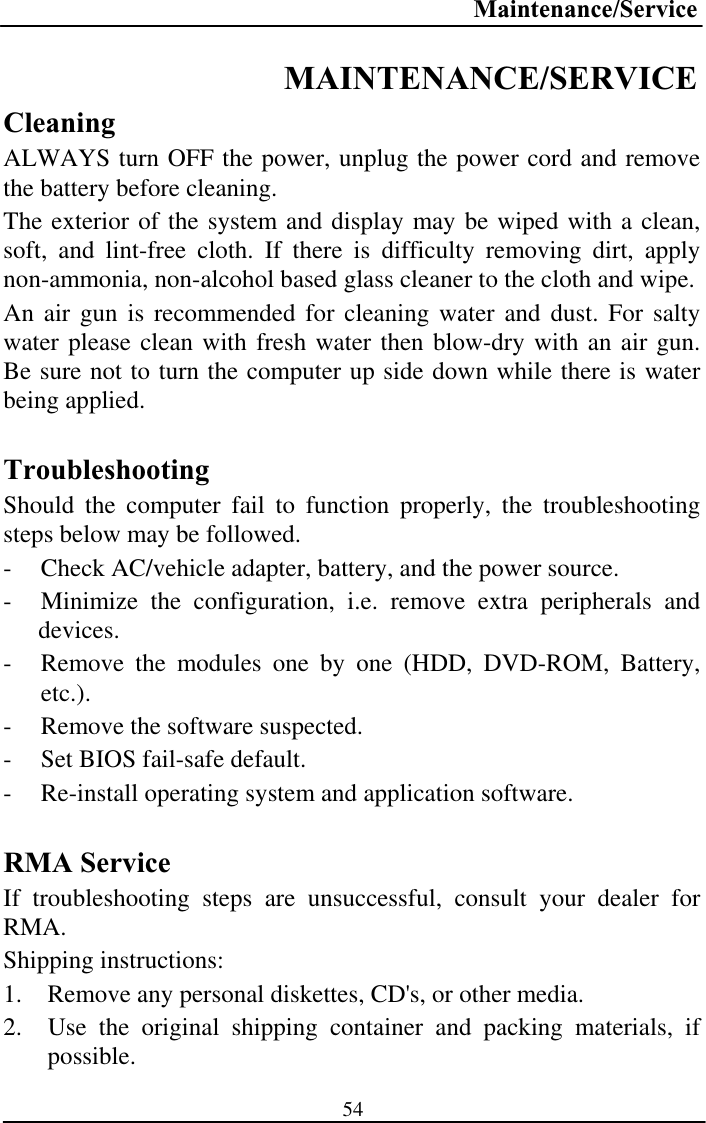
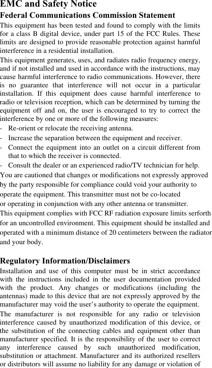
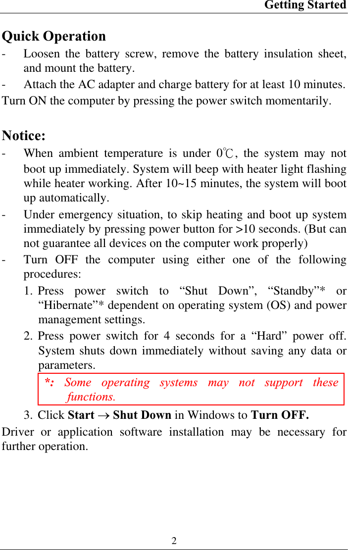
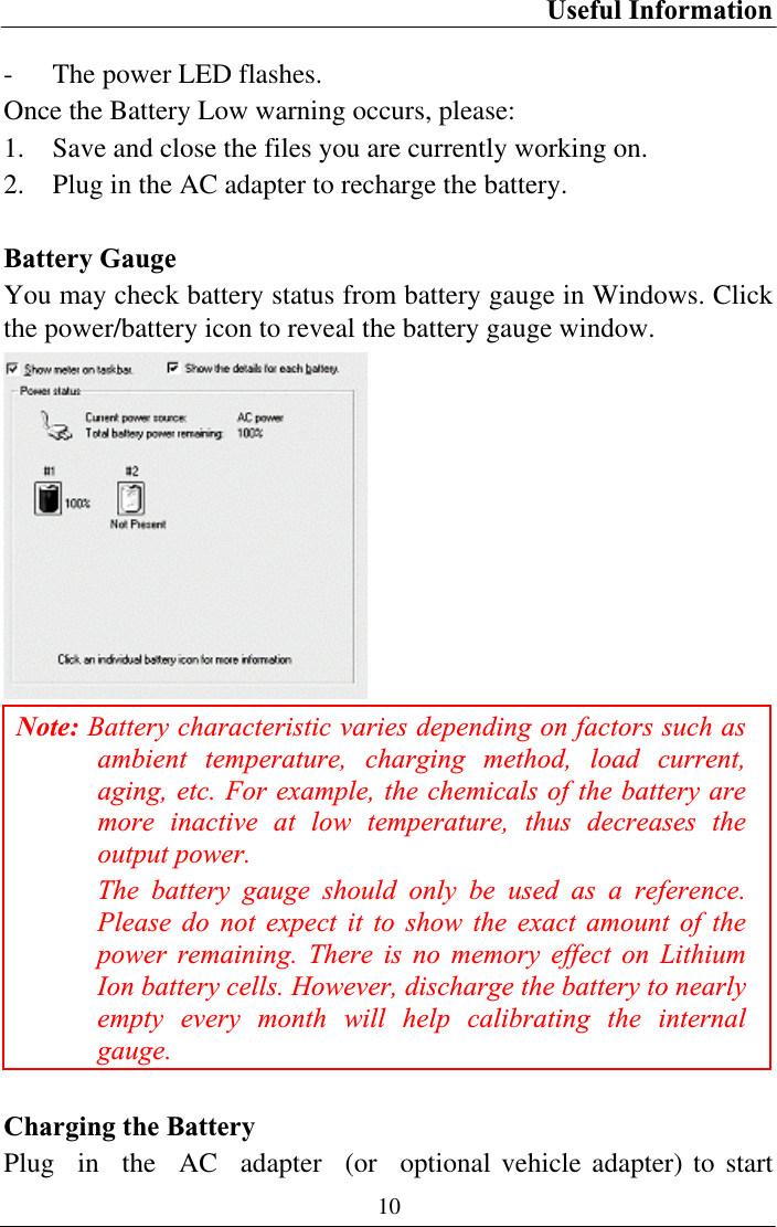
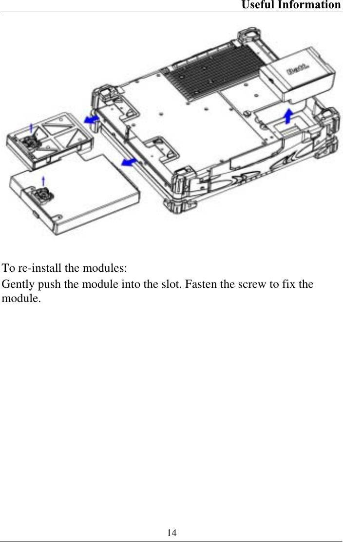
![BIOS Setup 33IDE Channel 0 Slave Sub-Menu Phoenix TrustedCore (tm) Setup Utility MainIDE Channel 0 Slave [None] Item Specific Help Type: [Auto] Multi-Sector Transfers: [Disabled] LBA Mode Control: [Disabled] 32 Bit I/O: [Disabled] Transfer Mode: [Standard] Ultra DMA Mode: [Disabled] SMART Monitoring: Disabled User = you enter parameters of hard-disk drive installed at this connection.Auto = autotypes hard-disk drive installed here. CD-ROM = a CD-ROM drive is installed here. ATAPI Removable = removable disk drive is installed here. F1 Help ĹĻ Select Item –/+ Change Values F9 Setup Defaults Esc Exit ļ Menu Enter Select Ź Sub-Menu F10 Save and ExitIDE Channel 0 Slave Sub-Menu Selections You can make the following selections on the IDE Channel 0 Slave Sub-Menu.Feature Options Description Type User AutoCD-ROMATAPI Removable User = you enter parameters of hard-disk drive installed at this connection. Auto = autotypes hard disk drive installed here. CD-ROM = a CD-ROM drive is installed here. ATAPI Removable = removable disk drive is installed here. 32 Bit I/O DisabledEnabledThis setting enables or disables 32 bit IDE data transfers.](https://usermanual.wiki/MilDef-Crete/RT886EX/User-Guide-1168665-Page-43.png)
![BIOS Setup 34IDE Channel 1 Master Sub-Menu Phoenix TrustedCore (tm) Setup Utility MainIDE Channel 1 Master [None] Item Specific Help Type: [Auto] Multi-Sector Transfers: [Disabled] LBA Mode Control: [Disabled] 32 Bit I/O: [Disabled] Transfer Mode: [Standard] Ultra DMA Mode: [Disabled] User = you enter parameters of hard-disk drive installed at this connection.Auto = autotypes hard-disk drive installed here. CD-ROM = a CD-ROM drive is installed here. ATAPI Removable = removable disk drive is installed here. F1 Help ĹĻ Select Item –/+ Change Values F9 Setup Defaults Esc Exit ļ Menu Enter Select Ź Sub-Menu F10 Save and Exit IDE Channel 1 Master Sub-Menu Selections You can make the following selections on the IDE Channel 1 Master sub-menu. Feature Options Description Type User AutoCD-ROMATAPI Removable User = you enter parameters of hard-disk drive installed at this connection. Auto = autotypes hard disk drive installed here. CD-ROM = a CD-ROM drive is installed here. ATAPI Removable = removable disk drive is installed here. 32 Bit I/O Disabled EnabledThis setting enables or disables 32 bit IDE data transfers.](https://usermanual.wiki/MilDef-Crete/RT886EX/User-Guide-1168665-Page-44.png)
![BIOS Setup 35IDE Channel 1 Slave Sub-Menu Phoenix TrustedCore (tm) Setup Utility MainIDE Channel 1 Slave [None] Item Specific Help Type: [Auto] Multi-Sector Transfers: [Disabled] LBA Mode Control: [Disabled] 32 Bit I/O: [Disabled] Transfer Mode: [Standard] Ultra DMA Mode: [Disabled] User = you enter parameters of hard-disk drive installed at this connection.Auto = autotypes hard-disk drive installed here. CD-ROM = a CD-ROM drive is installed here. ATAPI Removable = removable disk drive is installed here. F1 Help ĹĻ Select Item –/+ Change Values F9 Setup Defaults Esc Exit ļ Menu Enter Select Ź Sub-Menu F10 Save and Exit IDE Channel 1 Slave Sub-Menu Selections You can make the following selections on the IDE Channel 1 Slave sub-menu. Feature Options Description Type User AutoCD-ROMATAPI Removable User = you enter parameters of hard-disk drive installed at this connection. Auto = autotypes hard disk drive installed here. CD-ROM = a CD-ROM drive is installed here. ATAPI Removable = removable disk drive is installed here. 32 Bit I/O Disabled EnabledThis setting enables or disables 32 bit IDE data transfers.](https://usermanual.wiki/MilDef-Crete/RT886EX/User-Guide-1168665-Page-45.png)
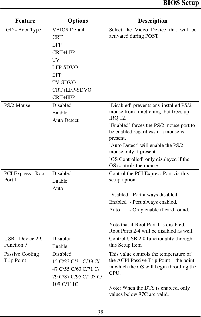
![BIOS Setup 37Advanced Menu Phoenix TrustedCore (tm) Setup Utility Main Advanced Security TPM State Boot ExitItem Specific Help Legacy USB Support: [Enabled] Summary screen: [Disabled] Boot-time Diagnostic Screen: [Enabled] QuickBoot Mode: [Enabled] Extended Memory Testing [Just zero it] IGD - Boot Type: [VBIOS Default] PS/2 Mouse [Auto Detect] PCI Express - Root Port 1: [Enabled] USB - Device 29, Function 7: [Enabled] Passive Cooling Trip Point [Disabled] • SIO SMC227 CONFGURATION Enable support for Legacy Universal Serial BusF1 Help ĹĻ Select Item –/+ Change Values F9 Setup DefaultsEsc Exit ļ Menu Enter Select Ź Sub-Menu F10 Save and Exit Warning: Incorrect settings may cause system malfunction. To correct it, restore the Setup Defaults with <F9>.Advanced Menu Selections You can make the following selections on the Advanced Menu. Feature Options Description Legacy USB Support DisabledEnableEnable support for Legacy Universal Serial Bus Summary screen Disabled EnableDisplay system configuration on boot Boot-timeDiagnostic Screen DisabledEnableDisplay the diagnostic screen during bootQuickBoot Mode Disabled EnableAllows the system to skip certain tests while booting. This will decrease the time needed to boot the system. Extended Memory Testing NormalJust zero it NoneDetermines which type of tests will be performed on extended memory (above 1M).](https://usermanual.wiki/MilDef-Crete/RT886EX/User-Guide-1168665-Page-47.png)
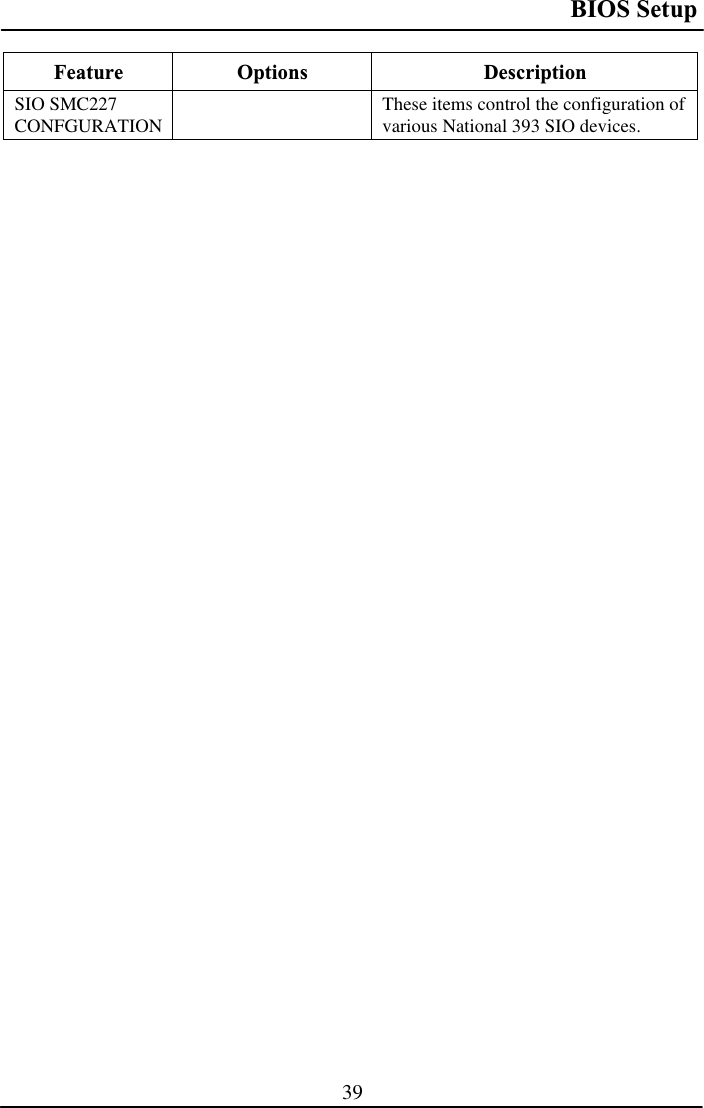
![BIOS Setup 40For most frequently altered setup “SIO SMC227 Configuration”, please refer following: Warning: Make sure internal COMx mode settings must be with the same type of the external connected devices. Otherwise it may cause serial components damage in either side.SIO SMC227 Configuration Sub-Menu Phoenix TrustedCore (tm) Setup Utility AdvancedSIO SMC227 CONFIGURATION Item Specific Help COM1 port: [3F8-IRQ 4] COM1 mode: [RS232] COM2 port: [2F8-IRQ 3] COM2 mode: [RS232] COM3 port: [3E8-IRQ 10] COM3 mode: [RS232] COM4 port: [2E8-IRQ 5] COM4 mode: [RS232] Printer1: [378-IRQ 7] Printer1 mode: [Standatd] Printer2: [378-IRQ 7]Configure COM1 using device options: [Disabled] No configuration [3F8-IRQ 4] Set the base I/O address for COM1 F1 Help ĹĻ Select Item –/+ Change Values F9 Setup Defaults Esc Exit ļ Menu Enter Select Ź Sub-Menu F10 Save and Exit SIO SMC227 Configuration Sub-Menu Selections You can make the following selections on the SIO SMC227 Configuration sub-menu. Feature Options Description COM1 port Disabled 3F8-IRQ 4 Configure COM1 using device options: [Disabled] No configuration [3F8-IRQ 4] Set the base I/O address for COM1](https://usermanual.wiki/MilDef-Crete/RT886EX/User-Guide-1168665-Page-50.png)
![BIOS Setup 41Feature Options Description COM1 mode RS232 TTL1Configure UART mode options: [RS332]ΚExternal Device [TTL1]ΚInternal Device COM2 port Disabled 2F8-IRQ 3 Configure COM2 using device options: [Disabled] No configuration [2F8-IRQ 3] Set the base I/O address for COM2 COM2 mode RS232 TTL2Configure UART mode options: [RS232]ΚExternal Device [TTL2]ΚInternal Device COM3 port Disabled 3E8-IRQ 10 Configure COM3 using device options: [Disabled] No configuration [3E8-IRQ 10] Set the base I/O address for COM3 COM3 mode RS232 TTL3Configure UART mode options: [RS232]ΚExternal Device [TTL3]ΚInternal Device COM4 port Disabled 2E8-IRQ 5 Configure COM4 using device options: [Disabled] No configuration [2E8-IRQ 5] Set the base I/O address for COM4 COM4 mode RS232 TTL4Configure UART mode options: [RS232]ΚExternal Device [TTL4]ΚInternal Device](https://usermanual.wiki/MilDef-Crete/RT886EX/User-Guide-1168665-Page-51.png)
![BIOS Setup 42Feature Options Description Printer1 Disabled 378-IRQ 4 Configure Printer1 device options: [Disabled] No configuration [378-IRQ 7] Set the base I/O address for Printer1 Printer1 mode Standard ECP EPP Configure Printer1 mode options: StandardEPP ECP Printer2 Disabled 3BCConfigure Printer2 device options: [Disabled] No configuration [3BC] Set the base I/O address for Printer2](https://usermanual.wiki/MilDef-Crete/RT886EX/User-Guide-1168665-Page-52.png)
![BIOS Setup 43Security Menu Warning: If you forget user/supervisor password, the computer has to send back to manufacturer and replace EEPROM to make it work again. Phoenix TrustedCore (tm) Setup Utility Main Advanced Security TPM State Boot ExitItem Specific Help Processor Serial Number [Disabled]Fixed disk boot sector: [Normal] Diskette access: [Supervisor]USB Interface: [Enabled] AC97 Audio Interface: [Auto] AC97 Modem Interface: [Auto] Cardbus/1394 Interface [Auto] • RF Security Control: Controls detection of Processor Serial No. System must be reset or restarted from power-on for settings to take effect. F1 Help ĹĻ Select Item –/+ Change Values F9 Setup Defaults Esc Exit ļ Menu Enter Select Ź Sub-Menu F10 Save and Exit Security Menu Selections You can make the following selections on the Security Menu.Feature Options Description Processor Serial Number DisabledEnabledControls detection of Processor Serial No. System must be reset or restarted from power-on for settings to take effect.Fixed disk boot sector NormalWrite Protect Write protects the boot sector on the hard disk to protect against viruses. Diskette access Supervisor UserControl access to diskette drives USB Interface Disabled EnabledControl the listed USB Functions by setting the item to the desired value.](https://usermanual.wiki/MilDef-Crete/RT886EX/User-Guide-1168665-Page-53.png)
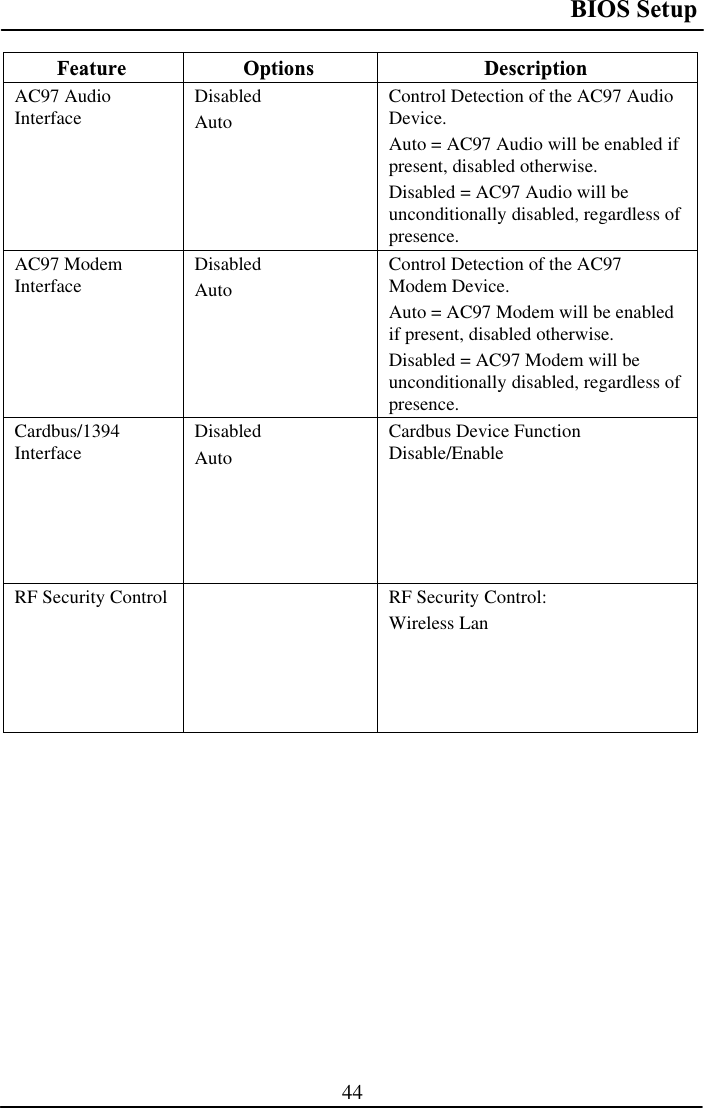
![BIOS Setup 45For most frequently altered setup “RF Security Control” please refer following:RF Security Control Sub-Menu Phoenix TrustedCore (tm) Setup Utility SecurityRF Security Control: Item Specific Help Wireless Lan: [Disabled] Wireless Lan Control F1 Help ĹĻ Select Item –/+ Change Values F9 Setup Defaults Esc Exit ļ Menu Enter Select Ź Sub-Menu F10 Save and Exit RF Security Control Sub-Menu Selections You can make the following selections on the RF Security Control sub-menu. Feature Options Description Wireless Lan Disabled EnabledWireless Lan Control Enabled Wireless function](https://usermanual.wiki/MilDef-Crete/RT886EX/User-Guide-1168665-Page-55.png)
![BIOS Setup 46TPM State Menu Phoenix TrustedCore (tm) Setup Utility Main Advanced Security TPM State Boot ExitItem Specific Help Current TPM State: Enabled and Deactivated Change TPM State: [No Change] Change TPM State F1 Help ĹĻ Select Item –/+ Change Values F9 Setup Defaults Esc Exit ļ Menu Enter Select Ź Sub-Menu F10 Save and Exit TPM State Menu Selections You can make the following selections on the TPM State Menu. Feature Options Description Change TPM State No Change Enable & Activate Deactivate & Disable ClearChange TPM State](https://usermanual.wiki/MilDef-Crete/RT886EX/User-Guide-1168665-Page-56.png)