Millennial Net MG5424XL MeshNode User Manual
Millennial Net MeshNode Users Manual
Users Manual

Document Number: DOC-0063
Revision: 05
Released: January 2008
MeshScape™
Commercial- and Industrial-class
Wireless Mesh Networks
RK-5424-5 Reference Kit
for 2.4 GHz MeshScape Systems
User’s Guide

COPYRIGHT
This manual is produced and copyrighted by Millennial Net, Inc. Any use or reproduction of the contents of this
manual without the prior written consent of Millennial Net, Inc. is strictly prohibited.
NOTICE
All title and copyrights to this document are owned by Millennial Net, Inc. No part of the contents of this document
may be reproduced or transmitted in any form or by any means without the written permission of Millennial Net, Inc.
Millennial Net, Inc. shall not be liable for errors contained herein. Millennial Net, Inc. shall not be liable for any
damages whatsoever, including, without limitation, damages for loss of business profits, business interruption, loss
of business information, or other pecuniary loss arising out of the use of this documentation even if Millennial Net,
Inc. has been made aware of the possibility of such damages.
Information contained in this document is subject to change without notice. While every effort is made to ensure
that the information is accurate as of the publication date, users are reminded to update their use of this document
with documents published by Millennial Net, Inc. subsequent to this date.
Third-party product information is for informational purposes only, and constitutes neither an endorsement nor a
recommendation. Millennial Net, Inc. expressly disclaims any responsibility with respect to the performance of the
third-party products.
Copyright © 2000 - 2008 by Millennial Net, Inc.
ALL RIGHTS RESERVED
Printed in U.S.A.
Millennial Net, Inc.
23 Third Avenue
Burlington, MA 01803 USA
+1 781.222.1030

RK-5424-5 Reference Kit User’s Guide v
CAUTION
Initialization of the product should be performed only by a qualified systems administrator.
Compliance Statements
FCC Compliance
FCC compliance for Millennial Net’s RK-5424-5 Reference Kit (2.4GHz, 5-3-1) consisting of the following
models/components:
• EN-5424 end node
• MN-5424 mesh node
• MG-5424XL MeshGate Extra Long Range gateway
Compliance Statement (Part 15.19)
The Millennial Net RK-5424-5 Reference Kit complies with Part 15 of the FCC Rules and with RSS-210 of
Industry Canada.
Operation is subject to the following two conditions:
(1) This device may not cause harmful interference, and
(2) This device must accept any interference received, including interference that may cause undesired
operation.
Warning (Part 15.21)
Changes or modifications not expressly approved by the party responsible for compliance could void the
user's authority to operate the equipment.
Note (Part 15.105(b))
This equipment has been tested and found to comply with the limits for a Class B digital device, pursuant to
part 15 of the FCC Rules. These limits are designed to provide reasonable protection against harmful
interference in a residential installation. This equipment generates, uses and can radiate radio frequency
energy and, if not installed and used in accordance with the instructions, may cause harmful interference to
radio communications. However, there is no guarantee that interference will not occur in a particular
installation. If this equipment does cause harmful interference to radio or television reception, which can be
determined by turning the equipment off and on, the user is encouraged to try to correct the interference by
one or more of the following measures:
• Reorient or relocate the receiving antenna.
• Increase the separation between the equipment and receiver.
• Connect the equipment into an outlet on a circuit different from that to which the receiver is
connected.
• Consult the dealer or an experienced radio/TV technician for help.

vi Millennial Net
Unlicensed Modular Approval (for OEMs)
The URM-G-2400 and URM-M-2400 comply with the FCC's 47CFR Part 15 rules and regulations as well as
Part 15 Unlicensed Modular Approval as outlined in DA 00-1407. Compliance with the Modular Approval
rules allows an OEM to integrate the URM-G-2400 and URM-M-2400 into other products without further
FCC certification of the intentional radiator, but an OEM must still test their final product to comply with
unintentional radiator requirements of 47CFCR Part 15.
Under the Modular Approval rules, an OEM must comply with the following when integrating the
URM-G-2400 and URM-M-2400 into an end product:
1. The OEM must ensure that FCC labeling requirements are met. This shall include a clearly visible label on
the exterior of the end product with the following nomenclature:
Contains FCC ID: R8N-MG5424XL
2. The OEM must only use the reverse polarity-SMA (RP-SMA) antennas listed below when integrating the
device into an end product. These antennas have been tested and approved for use with the
URM-G-2400 and URM-M-2400. Integrating the module using any other antenna will require testing to
ensure compliance with FCC rules and regulations.
Centurion ½ wave Antenna Part Number: WCR2400SMRP
3. The OEM must use the same cable type and of the same length or longer than that defined below. Use
of another cable type or of a shorter length will require testing to ensure compliance with FCC rules and
regulations.
RF Cable type: RG174
RF Cable Length: 5.9" +/- 0.13”
Millennial Net Cable P/N: CBL-0018-01
Industry Canada Compliance Statement
This device has been designed to operate with an antenna having a maximum gain of 2.65 dB. Antenna
having a higher gain is strictly prohibited per regulations of Industry Canada. The required antenna
impedance is 50 Ohms.
To reduce potential radio interference to other users, the antenna type and its gain should be so chosen that
the equivalent isotropically radiated power (EIRP) is not more than that required for successful
communication.
OEM Integration
The modules have the same requirements for integration into an OEM product for Industry Canada as it
does for FCC. The only difference being the labeling nomenclature required on the exterior of the OEM
product. The following must be clearly visible on the exterior of the OEM product:
Contains IC: 5172A-MG5424XL

RK-5424-5 Reference Kit User’s Guide vii
For countries not covered by FCC Part 15, Industry Canada RSSS-210, or CE
The RK-5424 -5 Reference Kits are to be used solely by professional engineers for the purpose of evaluating
the feasibility of low-power wireless data communications applications. The user's evaluation must be
limited to use of an assembled Kit within a laboratory setting which provides for adequate shielding of RF
emission which might be caused by operation of the Kit following assembly. In field testing, the assembled
device must not be operated in a residential area or any area where radio devices might be subject to
harmful electrical interference. Distribution and sale of the Kit is intended solely for use in future
development of devices which may be subject to FCC regulation, or other authorities governing radio
emission. This Kit may not be resold by users for any purpose. Accordingly, operation of the Kit in the
development of future devices is deemed within the discretion of the user and the user shall have all
responsibility for any compliance with any authority governing radio emission of such development or use,
including without limitation reducing electrical interference to legally acceptable levels. All products
developed by user must be approved by the authority governing radio emission prior to marketing or sale of
such products and user bears all responsibility for obtaining the approval as needed from any other authority
governing radio emission. If user has obtained the Kit for any purpose not identified above, including all
conditions of assembly and use, user should return Kit to Millennial Net, Inc. immediately.
Trademarks
© 2000 - 2008 Millennial Net, Inc. All rights reserved. Millennial Net™, MeshScape™, and Persistent Dynamic
Routing™ are trademarks of Millennial Net, Inc. All other trademarks are the property of their respective
owners.
Information subject to change.

viii Millennial Net

RK-5424-5 Reference Kit User’s Guide ix
Contents
About This Guide
Audience .................................................................................................................. xviii
Using This Guide ....................................................................................................... xviii
Symbols and Conventions ...........................................................................................xix
Contacting Millennial Net ........................................................................................... xx
World Wide Web.................................................................................................. xx
Customer Support ................................................................................................ xx
Technical Publications........................................................................................... xx
Additional Resources ............................................................................................ xx
1Introduction
Wireless Mesh Networking Overview ..........................................................................1-2
Defining Wireless Mesh Networks....................................................................... 1-2
Wireless Mesh Network Components ................................................................. 1-3
MeshScape System Overview ......................................................................................1-6
Core Elements of MeshScape System.................................................................. 1-6
MeshGate Extra Long Range Connection Options............................................... 1-7
Data Models..................................................................................................... 1-11
Low-Power Configuration................................................................................. 1-13
The MeshScape RK-5424-5 Reference Kit..................................................................1-14
Major Features ................................................................................................. 1-15
Reference Kit Contents..................................................................................... 1-15
Host PC Requirements ...................................................................................... 1-16
2Installing the MeshScape System
Installing the MeshScape Wireless Mesh Network .......................................................2-2
Installing the Hardware ...............................................................................................2-3
MeshGate Extra Long Range Setup (MG-5424XL) ............................................... 2-3
Mesh Node Setup (MN-5424) ........................................................................... 2-12
End Node Setup (EN-5424) ............................................................................... 2-16
Installing MeshScape Software..................................................................................2-19
Installing Contents of Millennial Net’s RK-5424 CD-ROM.................................. 2-19
Installing and Running MeshScape Serial Proxy Server....................................... 2-20
Launching MeshScape Network Monitor Using Windows ................................. 2-24
3Running MeshScape Network Monitor
MeshScape Network Monitor Overview ......................................................................3-2
Menu Bar ........................................................................................................... 3-3
MeshGate Extra Long Range............................................................................... 3-5
Device Counts .................................................................................................... 3-5
Sensor Node Details............................................................................................ 3-5
Configuring a Node’s Operation .................................................................................3-7
Configuring the Sample Interval of a Single Node ............................................... 3-9
Configuring the Sample Interval of all Network Nodes ...................................... 3-10

xMillennial Net
Configuring Digital I/O Operation ...................................................................... 3-10
Configuring UART Operation............................................................................. 3-13
Configuring AD (analog-to-digital) Converter Operation.................................... 3-15
Using Watch Function to Display Configuration Information.............................. 3-17
Labeling an End Node or Mesh Node ........................................................................3-19
Configuring Persistence Attributes ............................................................................3-20
Setting the MeshScape Time.....................................................................................3-21
Specifying the MeshScape Connection Port ..............................................................3-22
Configuring Serial and ADC Data Formats ................................................................3-23
Turning Event Tracking On/Off..................................................................................3-24
Creating an Event Log File ........................................................................................3-25
Viewing the Contents of an Event Log File ................................................................3-26
Viewing MeshScape Statistics ...................................................................................3-28
Rebooting a Node.....................................................................................................3-30
Modifying a Node’s Network/Identity........................................................................3-31
Modifying a Node’s Operating Channel ....................................................................3-32
4Using the MeshScape API
Using the MeshScape API ...........................................................................................4-2
MeshScape API Directory Structure .............................................................................4-3
MeshScape API Functions Overview ............................................................................4-5
iBeanAPI.h ..................................................................................................................4-8
Data Structures ................................................................................................... 4-8
Functions .......................................................................................................... 4-17
iBeanAPI_IO.h...........................................................................................................4-36
Data Structures ................................................................................................. 4-36
Functions .......................................................................................................... 4-38
iBeanAPI_Utils.h........................................................................................................4-46
Functions .......................................................................................................... 4-46
iBeanAPI_LPR.h.........................................................................................................4-50
Functions .......................................................................................................... 4-50
iBeanAPI_performance.h...........................................................................................4-53
Data Structures ................................................................................................. 4-53
Functions .......................................................................................................... 4-55
Example API Code ....................................................................................................4-56
ARunning the Demo Application
Running the MeshScape Demo Program .................................................................... A-2
Running the Temperature Sensor Demo..................................................................... A-3
BUsing MeshScape Programmer
Getting Started with MeshScape Programmer.............................................................B-2
Connecting the Target Device to Your Computer ................................................ B-2
Launching MeshScape Programmer Using Windows............................................ B-5
Performing MeshScape Programmer Operations .........................................................B-6
Upgrading Firmware on the Target Device........................................................... B-6
Unlocking Features on the Target Device ............................................................. B-7
Reprogramming the Group and Device IDs on the Target Device ......................... B-8
Reprogramming the Target Device’s Radio Configuration .................................... B-9

RK-5424-5 Reference Kit User’s Guide xi
CSetting Up the Digi One SP
Overview.................................................................................................................... C-2
Installation and Configuration Procedure.................................................................... C-4
Connect the Digi One SP to your network. ......................................................... C-4
Install the Digi Connectware software. ............................................................... C-4
Use the Digi Discovery tool to enable a TCP/IP Connection.................................. C-7
Start MeshScape Network Monitor. .................................................................. C-12
DAccessing the MeshGate CLI
Connecting to the MeshGate CLI ............................................................................... D-2
Configuring the MeshGate Serial Port Settings ........................................................... D-3
Glossary

xii Millennial Net

RK-5424-5 Reference Kit User’s Guide xiii
Figures
Figure 1-1. Untethered, mobile ad hoc network nodes................................................... 1-2
Figure 1-2. Basic wireless mesh network components .................................................... 1-4
Figure 1-3. Adding a mesh node module ....................................................................... 1-4
Figure 1-4. MeshScape system core elements................................................................. 1-6
Figure 1-5. Direct serial connection to the MeshGate ..................................................... 1-8
Figure 1-6. Connection to the MeshGate via the MeshScape serial proxy server ............. 1-9
Figure 1-7. Connection to the MeshGate via Ethernet-to-serial Adapter ....................... 1-10
Figure 2-8. MeshGate Extra Long Range components .................................................... 2-3
Figure 2-9. Mounting the MeshGate Extra Long Range to a DIN rail............................... 2-5
Figure 2-10. Direct serial connection to the MeshGate Extra Long Range ......................... 2-6
Figure 2-11. Connection to the MeshGate via the MeshScape serial proxy server ............. 2-7
Figure 2-12. Connection to the MeshGate via Ethernet-to-serial Adapter ......................... 2-9
Figure 2-13. Mesh node components............................................................................. 2-12
Figure 2-14. End node and terminal board (top and bottom views) ................................ 2-16
Figure 2-15. MeshScape Serial Proxy Server running under Windows ............................. 2-21
Figure 2-16. Using Windows’ Start menu to launch MeshScape Network Monitor ......... 2-25
Figure 3-17. Sample MeshScape Network Monitor window ............................................. 3-2
Figure 3-18. MeshScape Network Monitor’s Device window ............................................ 3-7
Figure 3-19. Configuring sample interval of single node................................................... 3-9
Figure 3-20. Configuring sample interval of all nodes..................................................... 3-10
Figure 3-21. Configuring End Node or mesh node for digital I/O .................................... 3-12
Figure 3-22. Configuring End Node or mesh node for UART operation .......................... 3-14
Figure 3-23. Configuring End Node/Mesh Node for analog I/O....................................... 3-16
Figure 3-24. Displaying I/O information using Watch function........................................ 3-17
Figure 3-25. Labeling an End Node or Mesh Node ......................................................... 3-19
Figure 3-26. Configuring node persistence attributes ..................................................... 3-20
Figure 3-27. Setting the MeshScape Time ...................................................................... 3-21
Figure 3-28. Specifying the MeshScape connection port ................................................ 3-22
Figure 3-29. Configuring serial and ADC data formats ................................................... 3-23
Figure 3-30. Turning device event tracking on/off .......................................................... 3-24
Figure 3-31. Configure an event log file......................................................................... 3-25
Figure 3-32. View contents of event log file ................................................................... 3-26
Figure 3-33. Viewing MeshScape statistics ..................................................................... 3-29
Figure 3-34. Rebooting a node ...................................................................................... 3-30
Figure 3-35. Modifying a node’s network/identity .......................................................... 3-31
Figure 3-36. Modifying a node’s operating channel ....................................................... 3-32
Figure 4-1. Using the MeshScape API............................................................................. 4-2
Figure 4-2. MeshScape API directories............................................................................ 4-3
Figure A-1. MeshScape Demo main window .................................................................. A-2
Figure A-2. End node terminal board with kele temperature sensor................................ A-3
Figure B-1. Connecting MeshGate programming cable to a mesh node ......................... B-3
Figure B-2. Connecting MeshGate programming cable to an end node.......................... B-3
Figure B-3. Module programming terminal board .......................................................... B-4
Figure B-4. The MeshScape Programmer main window.................................................. B-6
Figure C-1. Connection to the MeshGate via Ethernet-to-serial Adapter ......................... C-3
Figure D-1. MeshGate CLI main menu............................................................................ D-3

xiv Millennial Net
Figure D-2. CLI administration commands...................................................................... D-3
Figure D-3. CLI serial port commands............................................................................. D-4

RK-5424-5 Reference Kit User’s Guide xv
Tables
Table 2-1. MeshGate terminal block pin assignments..................................................... 2-4
Table 2-2. MeshGate Extra Long Range status LEDs ..................................................... 2-10
Table 2-3. MeshGate Extra Long Range default Settings .............................................. 2-11
Table 2-4. Mesh Node terminal block pin assignments ................................................. 2-12
Table 2-5. Mesh node status LEDs................................................................................ 2-14
Table 2-6. MeshScape mesh node default settings ....................................................... 2-14
Table 2-7. MeshScape end node default settings ......................................................... 2-17
Table 3-8. Device window functions .............................................................................. 3-7
Table 3-9. Watch window functions ............................................................................ 3-18
Table 3-10. Event log key definitions.............................................................................. 3-27
Table 4-1. MeshScape API functions.............................................................................. 4-5

xvi Millennial Net

RK-5424-5 Reference Kit User’s Guide xvii
About This Guide
This section provides information related to the content of the user guide:
•’Audience’ on page xviii
•’Using This Guide’ on page xviii
•’Symbols and Conventions’ on page xix
•’Contacting Millennial Net’ on page xx

xviii Millennial Net
Audience
This guide is intended for the following qualified service personnel who are responsible for
installing, operating, and developing software to interface with the RK-5424-5 MeshScape
Wireless Mesh Network Reference Kit:
• System installer
• Hardware technician
• System operator
• System administrator
• Software developer
Using This Guide
The sections of this guide provide the following information:
Section Provides
Chapter 1, “Introduction” General overview of wireless mesh networking and the MeshScape™
system.
Chapter 2, “Installing the MeshScape System” Instructions for installing the components of the RK-5424-5
MeshScape Wireless Mesh Network Reference Kit (MeshGate,
Mesh Nodes, End Nodes) and MeshScape Network Monitor (GUI).
Chapter 3, “Running MeshScape Network
Monitor”
Procedures for using MeshScape Network Monitor software to
configure the MeshScape system nodes. Also includes information for
attaching external I/O devices to an End Node or Mesh Node.
Chapter 4, “Using the MeshScape API” Information on the MeshScape API functions.
Appendix A, “Running the Demo Application” Procedure for running the sample application provided with the
reference kit.
Appendix B, “Using MeshScape Programmer” Instructions for using the MeshScape Programmer application to
upgrade the firmware on MeshScape devices, reprogram the group and
device IDs, and select the channel on which the devices operate.
Appendix C, “Setting Up the Digi One SP” High-level configuration procedures for the Digi One SP
Ethernet-to-serial adapter when used to provide an Ethernet connection
for the MeshGate.
Appendix D, “Accessing the MeshGate CLI” Describes how to access the MeshGate command line interface (CLI) to
verify and configure the MeshGate serial port settings.
Glossary Defines terminology associated with wireless mesh networking and the
MeshScape system.
Index An alphabetical index of topics described in this manual.
RK-5424-5 Reference Kit User’s Guide xix
Symbols and Conventions
This guide uses the following symbols and conventions to emphasize certain information.
Italics - Indicate the first occurrence of a new term, book title, and emphasized text.
1. Numbered list - Where the order of the items is important.
• Bulleted list - Where the items are of equal importance and their order is unimportant.
Note: A note is used to highlight important information relating to the topic being
discussed.
Caution
A caution means that a specific action could cause harm to the equipment or
to the data.
Warning
A warning describes an action that could result in physical injury, or
destruction of property.
Hazard
A hazard is a particular form of warning related expressly to electric shock.

xx Millennial Net
Contacting Millennial Net
World Wide Web
Millennial Net maintains a site on the World Wide Web where information on the company and
its products can be found. The URL is:
www.millennialnet.com
Customer Support
For answers to your technical questions, Millennial Net’s Customer Service department can be
reached at:
phone:
+1 781.222.1030
e-mail:
support@millennialnet.com
Technical Publications
Millennial Net is committed to providing you with quality technical documentation. Your
feedback is valuable and appreciated. Please send comments, suggestions, and enhancements
regarding this guide or any Millennial Net documentation to:
support@millennialnet.com
Please include the document title, number, and version in your email.
Additional Resources
To obtain additional resources and information about wireless mesh networking and the
development and deployment of MeshScape-based applications, visit the resources page on our
Web site at:
www.millennialnet.com/resources
There you will find links to:
• Application notes
• Articles
• Brochures and data sheets
• Case studies
• Industry notes
• Source book
• White papers

RK-5424-5 Reference Kit User’s Guide 1-1
1
Introduction
This chapter provides an overview of the MeshScape system and Reference Kit. In this chapter
you will find:
•’Wireless Mesh Networking Overview’ on page 1-2
•’MeshScape System Overview’ on page 1-6
•’The MeshScape RK-5424-5 Reference Kit’ on page 1-14
1-2 Millennial Net
Introduction
Wireless Mesh Networking Overview
This section provides you with a basic understanding of wireless mesh network concepts and
components.
Defining Wireless Mesh Networks
Until recently, networks designed for monitoring and controlling sensors or actuators on a
network were limited in application and scope due to a major network design
consideration—the cables required to connect the various sensors and actuators to a
centralized collection point. In addition to the costs associated with installing and maintaining
communication cables (fiber optic or copper), this type of network infrastructure prevents
sensor mobility and severely limits the feasible applications of such a network.
Thanks to significant advances in low-power radio and digital circuit design, self-organizing
wireless mesh networks are now a reality. Sensors of all types (temperature, motion, occupancy,
vibration, etc.) can now be wirelessly enabled and deployed inexpensively and quickly.
Wireless mesh networks fundamentally change the economics of deploying and operating a
sensor network, unlocking opportunities to achieve new efficiencies in applications such as
production processes, building control, or monitoring. Wireless mesh networks also enable the
development of a brand new class of applications and services not previously possible with
wired sensor networks.
As illustrated in Figure 1-1, wireless mesh networks form what is called a wireless ad hoc
network, which refers to a network’s ability to self-organize and self-heal. This means there are
no administrative duties associated with establishing and maintaining a wireless mesh network.
By comparison, a wired infrastructure network, such as the LAN found in most office
environments, requires a significant amount of overhead to install and maintain in terms of
cabling and administrative time.
Figure 1-1. Untethered, mobile ad hoc network nodes
Mobile network node

RK-5424-5 Reference Kit User’s Guide 1-3
Wireless Mesh Networking Overview
In an ad hoc network, sensor nodes consisting of a sensor attached to a wireless module can be
randomly placed and moved as needed. If the network needs to scale up, additional sensor
nodes are easily added. The new sensor nodes and surrounding network will do the work of
discovering each other and establishing communication paths through single- and multi-hop
paths. All this is made possible through the use of robust, efficient network protocols
developed specifically for wireless mesh networks.
Wireless Mesh Network Components
This section describes the software and hardware that comprise a wireless mesh network.
System Software
The software required to integrate and operate a wireless mesh network resides as firmware in
the system modules and in the application platform as a set of API functions or network
monitoring system (NMS).
Module Firmware
Module firmware is a small, efficient piece of code that incorporates the module into a larger ad
hoc network. It “drives” the module's operation as part of the larger ad hoc network.
The firmware is also responsible for packaging the analog and digital sensor data into digital
packets and delivering them across the wireless mesh network.Firmware is pre-programmed
onto every MeshScape component. However, you have the opportunity to modify certain
network parameters for each component. See Appendix B for more information.
API
An API, or application programming interface, is a set of commonly used functions for
streamlining application development. Used by application developers, an API provides hooks to
integrate the application platforms with the modules on the wireless mesh network.
API functions are grouped into “libraries.” In wireless mesh networks, there are two different
API libraries:
• High-level library: These functions are used to integrate the application with the gateway
module.
• Low-level library: These functions are used to integrate the sensor/actuator with the end
node module.
Network Monitoring System
A network monitoring system (NMS) is software used to interface with a particular wireless
mesh network, eliminating the need for any programming. Through the NMS’s graphical user
interface (GUI), network operators are able to see the various nodes of their wireless mesh
network. Depending on the type of network, control commands can also be issued through the
NMS. For example, a pin on a digital interface between an end node and an actuator can be set
to high to change the state of the actuator.
1-4 Millennial Net
Introduction
System Modules
The modules of a wireless mesh network enable wireless connectivity within the network,
connecting an application platform at one end of the network with one or more sensor or
actuator devices at the other end. As shown in Figure 1-2, the gateway and end node modules
create a transparent, wireless data path between the application platform and sensor.
Figure 1-2. Basic wireless mesh network components
Exchange of analog or digital information between an application platform and one or more
sensor nodes takes place in a wireless fashion. In this example, the data path between the
gateway and end node is referred to as a single-hop network link.
To extend the range of a network or circumvent an obstacle, a wireless mesh node module can
be added between a gateway and an end node as shown in Figure 1-3.
Figure 1-3. Adding a mesh node module
This particular example represents a multi-hop data path, in which data packets are handed off
from one module to the next before reaching their destination (gateway-to-mesh node-to-end
node and vice versa).
More elaborate network layouts are discussed later in Network Topologies,” but for now, we’ll
take a closer look at each of the network components shown in Figure 1-3.
Application Platform
This is the network device (network controller, PC, handheld, etc.) used to monitor and control
the actions of the various sensors and actuators that are connected to the wireless mesh
network. The application platform is capable of making decisions based on the information it
gathers from the network. Typically, the wireless mesh network will come with an API and/or a
GUI used to interface with the wireless modules.

RK-5424-5 Reference Kit User’s Guide 1-5
Wireless Mesh Networking Overview
Gateway
The gateway is the interface between the application platform and the wireless nodes on the
network. The gateway can be a discrete module, or it can be integrated onto a Flash card form
factor for use in, for example, a handheld device. All information received from the various
network nodes is aggregated by the gateway and forwarded on to the application platform. In
the reverse direction, when a command is issued by the application program to a network
node, the gateway relays the information to the wireless mesh network. The gateway can also
perform protocol conversion to enable the wireless network to work with other
industry-standard network protocols.
Mesh Node Module
Considered full-function devices (FFD), mesh node modules (sometimes called routers) are used
to extend network coverage area, route around obstacles, and provide back-up routes in case
of network congestion or device failure. In some cases, mesh nodes may also be connected via
analog and digital interfaces to sensors and actuators, providing the same I/O functionality of
an end node module. Mesh nodes can be battery powered or line powered.
End Node Module
Considered reduced-function devices (RFD), end nodes (sometimes called endpoints) provide
the physical interface between the wireless mesh network and the sensor or actuator to which
it is wired. End nodes will usually have one or more I/O connections for connecting to and
communicating with analog or digital sensor or actuator devices. End nodes are typically battery
powered.
Sensor/Actuator
These are the devices you ultimately wish to monitor and/or control. An example is a sensor
monitoring the pressure in an oil pipeline.
1-6 Millennial Net
Introduction
MeshScape System Overview
In order to realize benefits wireless mesh networking promises, the technology must be able to
address several critical requirements: reliability of data transmission, responsiveness to adapt to
dynamic environments, power efficiency, and scalability. The MeshScape™ wireless mesh
networking system from Millennial Net delivers on all of these requirements. The MeshScape
ready-to-embed hardware modules and assemblies support fast and cost-effective application
development.
Core Elements of MeshScape System
The core elements of the MeshScape wireless mesh networking system are depicted in
Figure 1-4 below.
Figure 1-4. MeshScape system core elements
MeshScape Networking Software
The ultra-efficient, highly scalable, self-organizing networking software is based on Persistent
Dynamic Routing™ techniques. The networking software is delivered on the hardware modules
described in this section. For volume applications, the MeshScape system software can also be
licensed and integrated directly onto your sensor assembly.
Millennial Net has developed and optimized its protocol to address the unique characteristics
and challenges associated with wireless mesh networking. The end result is a networking
system and associated protocol that is highly scalable, ultra-efficient, and extremely responsive
and resilient in dynamic environments. The MeshScape protocol for wireless mesh networks
provides the industry's longest battery life at sensor nodes while delivering data over
fault-tolerant links with end-to-end redundancy. The Millennial Net protocol is based on a set of
Data Models
Collect Broadcast Dialogue
Event
Driven Periodic
Sampling Store &
Forward Burst Stream Polling On
Demand
Network Monitor Application APIs
MeshScape Networking Software
w/ Persistent Dynamic Routing™
Hardware
ISM Bands
916 MHz. 2.4 Ghz
Modules
End Nodes Mesh
Nodes Gateways

RK-5424-5 Reference Kit User’s Guide 1-7
MeshScape System Overview
techniques including, Persistent Dynamic Routing for reliable and scalable wireless mesh
networks. When forming an ad hoc sensor network, Persistent Dynamic Routing requires
minimal overhead for requesting and establishing connectivity without relying on the
bandwidth-consuming flooding technique.
MeshScape Network Monitor and Application APIs
The MeshScape system delivers the tools to view and control network dynamics. The
MeshScape Network Monitor provides functions for monitoring and managing the network.
Application APIs streamline development by providing input/output functions for sensor and
application integration.
Hardware
The MeshScape system includes field-proven, “integratable” modules for fastest time to
market. These ready-to-integrate end nodes, mesh nodes, and gateways support numerous
application requirements and support various ISM bands for license-free operation around the
world.
MeshGate Extra Long Range Connection Options
The MeshGate Extra Long Range gateway is equipped with an RS-232 serial port that enables
the gateway to connect to a Windows XP host PC running the MeshScape Network Monitor
application, or to a Linux- or Windows-application platform (network controller, PDA, PC, etc.)
running a MeshScape API-based application.
Use one of the following options to establish a connection between the MeshScape Network
Monitor host PC and the MeshGate Extra Long Range:
• Establish a direct serial connection between the MeshScape Network Monitor host PC and
the MeshGate Extra Long Range using the supplied RS-232 cable.
• Establish a TCP/IP connection from the Network Monitor host PC to a MeshScape Serial
Proxy Server that has a direct serial connection to the MeshGate Extra Long Range. The
MeshScape Serial Proxy Server that runs on a Linux or Windows XP host is supplied with
your MeshScape RK-5424-5 Reference Kit software.
• Establish a TCP/IP connection from the Network Monitor host PC to an Ethernet-to-serial
adapter connected to the MeshGate Extra Long Range.
These MeshGate Extra Long Range connection options are described and depicted in the
following sections.
Regardless of which of the following serial connection options is used, the MeshScape Network
Monitor or other MeshScape API-based application can only access and monitor a single
MeshScape, i.e., a single instance of MeshScape Network Monitor cannot monitor multiple
MeshScapes.
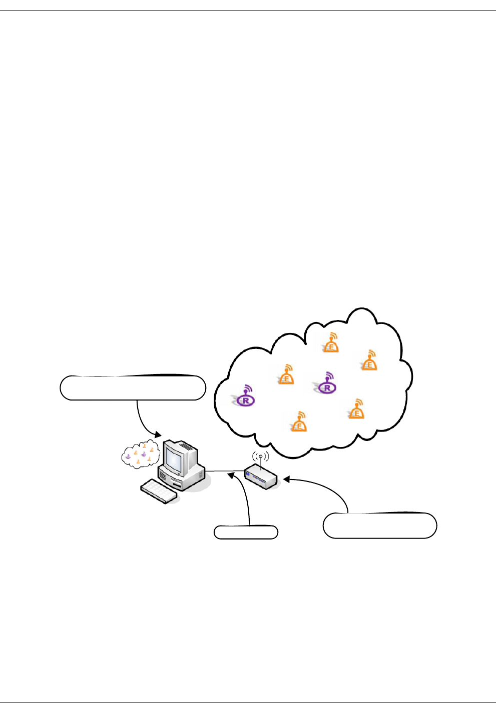
Direct Serial Connection
Figure 1-5 shows a local direct serial connection between the MeshScape Network Monitor
host PC and the MeshGate Extra Long Range using the supplied RS-232 cable.
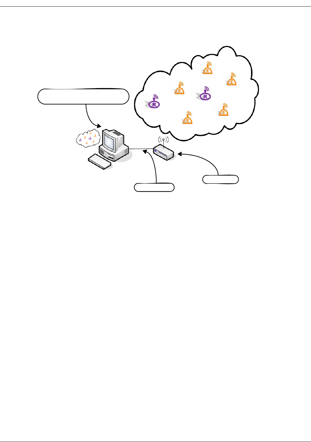
1-8 Millennial Net
Introduction
Figure 1-5. Direct serial connection to the MeshGate
In this topology, only one MeshScape API-based application running on the host PC can access
the MeshScape.
TCP/IP Connection to the MeshScape Serial Proxy Server
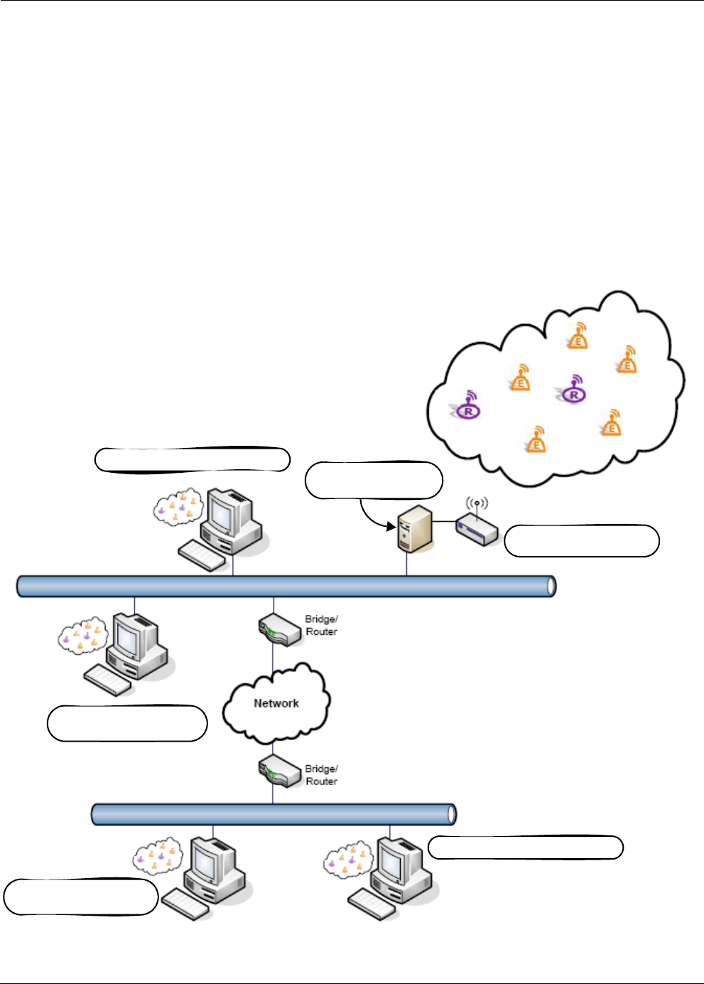
Figure 1-6 shows a PC that is running the MeshScape Serial Proxy Server and is connected to
the MeshGate Extra Long Range via the PC’s serial port.
A MeshScape API-based application functions as a serial proxy client by changing its lowest
level serial interface to a TCP/IP interface. The MeshScape API TCP/IP serial proxy client interface
opens a connection to the MeshScape Serial Proxy Server by connecting to its well advertised
port.
Local and remote MeshScape API-based applications including MeshScape Network Monitor
access the MeshScape data on the MeshGate Extra Long Range by connecting to the
MeshScape Serial Proxy Server at IP address 10.0.0.90 on port 45090.
Although Figure 1-6 does not show any MeshScape API-based applications running on the PC,
any number of MeshScape API-based applications could be running on the same PC host as the
MeshScape Serial Proxy Server. The MeshScape Serial Proxy Server supports up to ten client
connections.
RS-232 Cable
MeshGate
MeshScape Network Monitor
Host PC
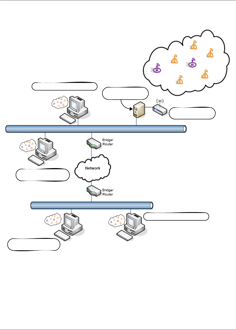
RK-5424-5 Reference Kit User’s Guide 1-9
MeshScape System Overview
Figure 1-6. Connection to the MeshGate via the MeshScape serial proxy server
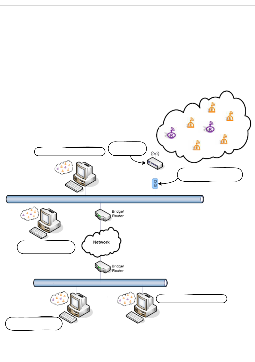
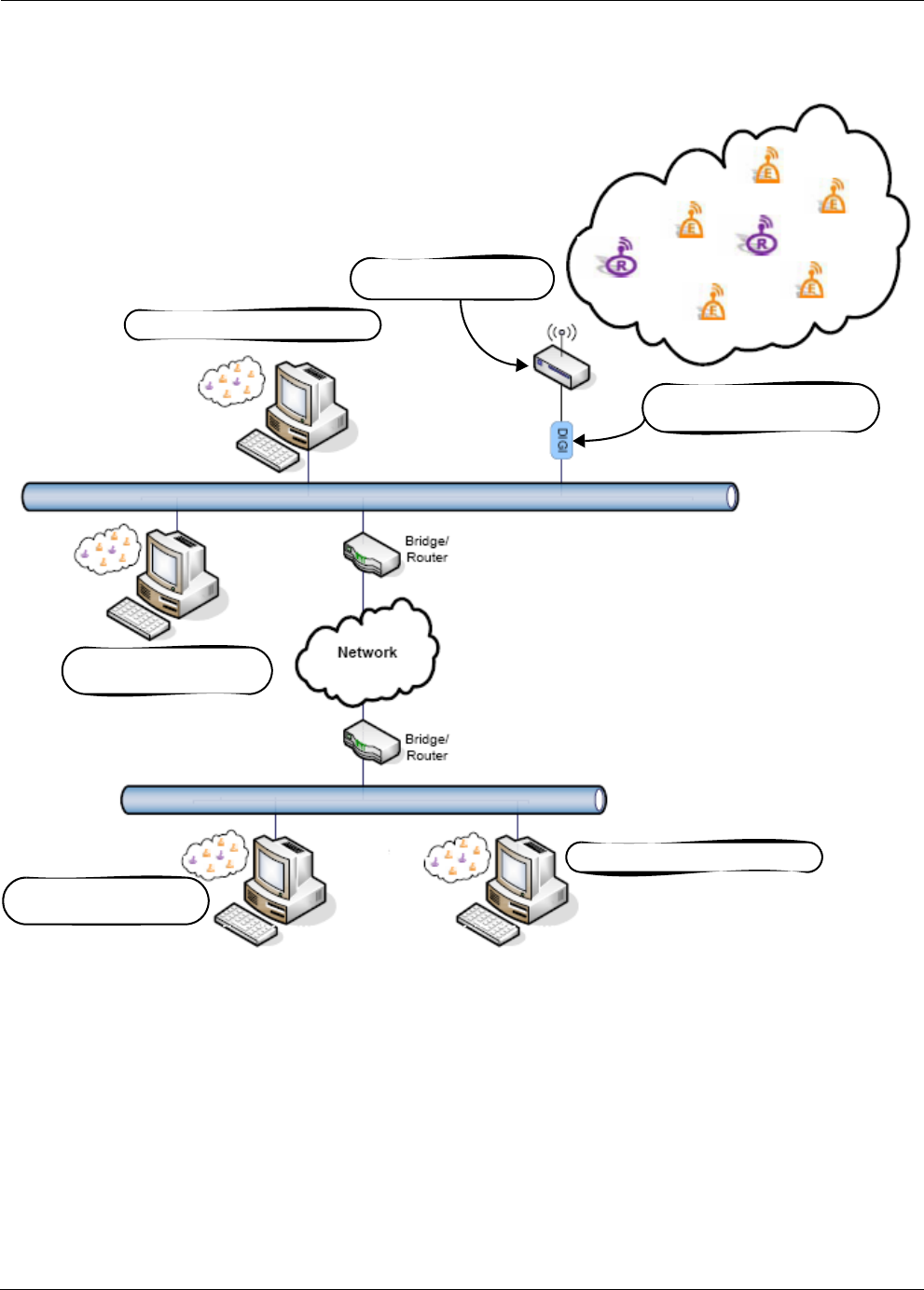
TCP/IP Connection to an Ethernet-to-serial Adapter
Figure 1-7 shows a MeshGate Extra Long Range connected to an Ethernet network using an
Ethernet-to-serial adapter. The Ethernet-to-serial adapter has both an RJ-45 Ethernet connector
and a DB-9 serial connector. The device accepts TCP/IP packetized serial data from the Ethernet,
extracts the raw data, and forwards it out the serial port. The reverse operation is performed in
the serial-to-Ethernet direction.
MeshGate Extra
Long Range
MeshScape Network Monitor
MeshScape Network Monitor
MeshScape API-based
Application
MeshScape API-based
Application
Serial Proxy Server
10.0.0.90:45090
1-10 Millennial Net
Introduction
Local and remote MeshScape API-based applications including MeshScape Network Monitor
access the MeshScape data on the MeshGate Extra Long Range by connecting to the
MeshScape Serial Proxy Server at IP address 10.0.0.90 on port 2101.
Millennial Net has qualified the Digi One SP Ethernet-to-serial adapter for use with MeshScape
wireless mesh networks. Appendix C of this user’s guide presents a high-level configuration
procedure for the Digi One SP Ethernet-to-serial adapter when used to provide an Ethernet
connection for the MeshGate Extra Long Range.
Figure 1-7. Connection to the MeshGate via Ethernet-to-serial Adapter
MeshGate Extra
Long Range
MeshScape Network Monitor
MeshScape Network Monitor
MeshScape API-based
Application
MeshScape API-based
Application
Ethernet-to-serial Adapter
10.0.0.90:2101

RK-5424-5 Reference Kit User’s Guide 1-11
MeshScape System Overview
Data Models
The MeshScape system provides built-in support for data movement profiles to speed
development including:
• data collection models
• bi-directional dialogue models
•broadcast models
These data models optimize the network for an application’s specific data requirements and
support a variety of classes for collection and bi-directional dialogue data models.
Data Collection Models
Data collection models describe monitoring applications where the data flows primarily from
the sensor node to the gateway. The MeshScape system supports the data collection models
described in this section.
Periodic Sampling
For applications where certain conditions or processes need to be monitored constantly, such as
the temperature in a conditioned space or pressure in a process pipeline, sensor data is acquired
from a number of remote sensor nodes and forwarded to the gateway or data collection center
on a periodic basis.
The sampling period mainly depends on how fast the condition or process varies and what
intrinsic characteristics need to be captured. In many cases, the dynamics of the condition or
process to be monitored can slow down or speed up from time to time. Therefore, if the sensor
node can adapt its sampling rate to the changing dynamics of the condition or process,
over-sampling can be minimized and power efficiency of the overall network system can be
further improved.
Another critical design issue associated with periodic sampling applications is the phase relation
among multiple sensor nodes. If two sensor nodes operate with identical or similar sampling
rates, collisions between packets from the two nodes is likely to happen repeatedly. It is
essential that sensor nodes can detect this repeated collision and introduce a phase shift
between the two transmission sequences in order to avoid further collisions resulting in optimal
network operation and minimized power usage.
Event Driven
There are many cases that require monitoring one or more crucial variables immediately
following a specific event or condition. Common examples include fire alarms, door and
window sensors, or instruments that are user activated. To support event-driven operations
with adequate power efficiency and speed of response, the sensor node must be designed such
that its power consumption is minimal in the absence of any triggering event, and the wake-up
time is relatively short when the specific event or condition occurs. Many applications require a
combination of event driven data collection and periodic sampling.

1-12 Millennial Net
Introduction
Store and Forward
In many applications, data can be captured and stored or even processed by a sensor node
before it is transmitted to the gateway or base station. Instead of immediately transmitting
every data unit as it is acquired, aggregating and processing data by remote sensor nodes can
potentially improve overall network performance in both power consumption and bandwidth
efficiency. One example of a store-and-forward application is cold-chain management where
the temperature in a freight container carrying produce or pharmaceuticals, for instance, is
captured and stored; when the shipment is received, the temperature readings from the trip are
downloaded and viewed to ensure that the temperature and humidity stayed within the desired
range.
Bi-Directional Dialogue Data Models
Bi-directional dialogue data models are characterized by a need for two-way communication
between the sensor/actuator nodes and gateway/application. The MeshScape system supports
the bi-directional dialogue data models described in this section.
Polling
Controller-based applications, such as those found in building automation systems, use a
polling data model. In this model, there is an initial device discovery process that associates a
device ID with each physical device in the network. The controller then polls each device on the
network successively, typically by sending a serial query message and waiting for a response to
that message. For example, an energy management application would use a polling data model
to enable the application controllers to poll thermostats, variable air volume sensors, and other
devices for temperature and other readings.
On-Demand
The on-demand data model supports highly mobile nodes in the network where a gateway
device enters the network, automatically binds to that network and gathers data, then leaves
the network. With this model, one mobile gateway can bind to multiple networks and multiple
mobile gateways can bind to a given network. An example of an application using the
on-demand data model is a medical monitoring application where patients in a hospital wear
sensors to monitor vital signs and doctors access that data via a PDA that is a mobile gateway. A
doctor enters a room and the mobile PDA automatically binds with the network associated with
that patient and downloads vital sensor data. When the doctor enters a second patient's room,
the PDA automatically binds with that network and downloads the second patient's data.
Broadcast Data Models
Broadcast data models are characterized by a need for one-to-many communication between
the gateway/application and sensor/actuator nodes. The MeshScape system supports the
broadcast data models described in this section.
Burst
The burst data model is characterized by an uneven pattern of data transmission from the
gateway/application to all sensor/actuator nodes on the wireless mesh network. The burst data
model has been used with industrial lighting applications.

RK-5424-5 Reference Kit User’s Guide 1-13
MeshScape System Overview
Stream
In the stream data model, the gateway/application sends data in a continuous stream to all
sensor/actuator nodes on the wireless mesh network. The transport service guarantees that all
data is delivered to the other end in the same order as sent and without duplicates. The stream
data model is used when performing network upgrades.
Low-Power Configuration
Many sensors are dispersed over a wide area and must rely on batteries or solar cells for their
power source. Consider the example of sensors taking measurements on a gas pad, it would be
prohibitively expensive to network these sensors using cables, so a wireless mesh network is the
perfect solution. However, to be useful in such an environment, the wireless mesh network
must posses the following characteristics:
• Power: Low power consumption—sensor and node must be able to operate 10+ years on
a singe battery
• Scalability: End nodes must be able to scale as sensor node counts increase.
• Data Rate: Application/gateway must support a configurable sample rate.
• Range: End nodes must be able to communicate over distances of 60 to 80 feet (18 to 24
meters) and Mesh nodes must be able to communicate at distances up to 100 feet (30
meters).
• Integration: The end nodes must be integrated with the sensor.
The MeshScape system possesses all of theses characteristics and uses configurable sleep and
duty cycle intervals to minimize power consumption.

1-14 Millennial Net
Introduction
The MeshScape RK-5424-5 Reference Kit
Millennial Net's RK-5424-5 Reference Kit contains everything you need to set up a
self-organizing, wireless star-mesh network. Once installed, you are able to observe the
performance and operation of the network components and prototype your application.
The RK-5424-5 Reference Kit hardware includes:
• one MeshGate Extra Long Range Gateway
• three mesh nodes
• five end nodes
• connecting cables
Reference kit software includes:
• MeshScape Network Monitor - the MeshScape system network monitoring tool and
graphical user interface (GUI)
• MeshScape Programmer application - enables you to upgrade the firmware on MeshGate
Extra Long Range gateways, mesh nodes, and end nodes, and modify the group and
device IDs of deployed mesh nodes and end nodes (see Appendix B, “Using MeshScape
Programmer”)
• Application Program Interface (API) library - A complete API library is provided to
streamline development using MS Visual C++.NET on a PC. For applications where the
MeshGate Extra Long Range connects to a third-party controller, Millennial Net also
provides libraries (pre-compiled Windows API library and Linux API library source), as well
as source code examples.
The kit also includes:
• temperature sensor assembly - enables you to run a sample application
(see Appendix A, “Running the Demo Application”).
Documentation for the reference kit includes:
• this user’s guide - which describes how to set up the MeshScape network, including
connections to the host computer, power supplies, sensors, and other devices
• MeshScape Product Family Sheet
• technical specifications for MeshGate Extra Long Range gateway, mesh node, and end
node
For complete details on the contents of the reference kit, refer to ’Reference Kit Contents’ on
page 1-15.
MeshScape Network Monitor runs on MS Windows XP and allows you to set network and
device operating parameters, and monitor the status of the MeshScape components and their
inputs/outputs. The API software runs on Windows and Linux systems and can be easily
incorporated into user application programs written in C++.

RK-5424-5 Reference Kit User’s Guide 1-15
The MeshScape RK-5424-5 Reference Kit
Major Features
Major features of the MeshScape RK-5424-5 Reference Kit include the following:
• frequency band: 2.4 GHz
• bi-directional/multiple-access communication
• MeshScape Network Monitor graphical user interface (GUI) for configuring the
MeshScape system and evaluating its performance
• Application Programming Interface (API)
• end node and mesh node-specific features include:
– configurable sampling interval
– digital I/O - 4 channels
– ADC input - 4 channels
– UART input/output
Reference Kit Contents
The MeshScape RK-5424-5 Reference Kit contains the following components:
• (4) EN-5424 end nodes; each end node is mounted to a terminal board equipped with a
battery.
• (1) EN-5424 end node mounted to a terminal board equipped with a battery and a Kele
temperature sensor for use with the supplied sample MeshScape application.
• (3) MN-5424 Mesh Nodes (enclosed) with AC power adapters.
• (1) MG-5424XL MeshGate Extra Long Range gateway (enclosed) with an AC power
adapter.
• (4) antennas; one 1/2-wave antenna for each Mesh Node and one for the MeshGate Extra
Long Range.
• (1) RS-232 serial cable for connecting the MeshGate Extra Long Range serial port to the
host PC. This is a DB-9, male-to-female, straight-through cable.
• (1) RS-232 serial cable for connecting the MeshGate Extra Long Range console port to the
host PC. This is a DB-9-to-mini-connector cable.
• (1) MeshGate programming cable
• (1) MeshGate-to-end node programming adapter
• (4) International power outlet adapter kits for supplied power adapters
• (1) CD-ROM containing support documentation and application software, including the
MeshScape Network Monitor program, MeshScape Programmer application, and API
software.

1-16 Millennial Net
Introduction
Host PC Requirements
The reference kit requires a personal computer (PC) to run the supplied application software.
The host PC must have the following minimal configuration:
• Microsoft Windows XP
• Processor: 1.0 GHz
•512 MB RAM
• RS-232 serial port
• CD-ROM drive for loading software
• Display with SVGA (800 x 600) resolution
• 10 MB free disk space
Although the above platform is required to run MeshScape Network Monitor and other
supplied applications, the supplied API library files are supported on both Windows and Linux
platforms.
Microsoft Visual C++ .NET is recommended for development purposes on Windows platforms.
Warning
These electronic products are sensitive to electrostatic discharge (ESD).
Permanent damage to these devices can result if subjected to high energy
electrostatic discharges.
Proper precautions are recommended to avoid performance degradation
or loss of functionality.

RK-5424-5 Reference Kit User’s Guide 2-1
2
Installing the MeshScape
System
This chapter provides the following MeshScape system installation information:
•’Installing the MeshScape Wireless Mesh Network’ on page 2-2
•’Installing the Hardware’ on page 2-3
•’Installing MeshScape Software’ on page 2-19

2-2 Millennial Net
Installing the MeshScape System
Installing the MeshScape Wireless Mesh
Network
This section of the user’s guide describes how to install the reference kit’s hardware and
software components. Installation should be performed in the following order:
1. MeshGate Extra Long Range (see ’MeshGate Extra Long Range Setup (MG-5424XL)’ on
page 2-3)
2. Mesh Nodes (see ’Mesh Node Setup (MN-5424)’ on page 2-12)
3. End Nodes (see ’End Node Setup (EN-5424)’ on page 2-16)
4. MeshScape Network Monitor (see ’Installing Contents of Millennial Net’s RK-5424
CD-ROM’ on page 2-19)
Once the hardware is set up and the MeshScape Network Monitor software installed, launch
MeshScape Network Monitor to verify that all hardware is detected and displayed.
RK-5424-5 Reference Kit User’s Guide 2-3
Installing the Hardware
Installing the Hardware
The following procedures describe in order, how to install the various hardware components of
the reference kit. When initially setting up the hardware, it is recommended that the MeshGate
Extra Long Range, Mesh Nodes, and End Nodes be placed close to the host PC. This will make
verifying proper network installation and operation easier when first establishing a session with
MeshScape Network Monitor. The devices can then be moved away from the host PC as
needed.
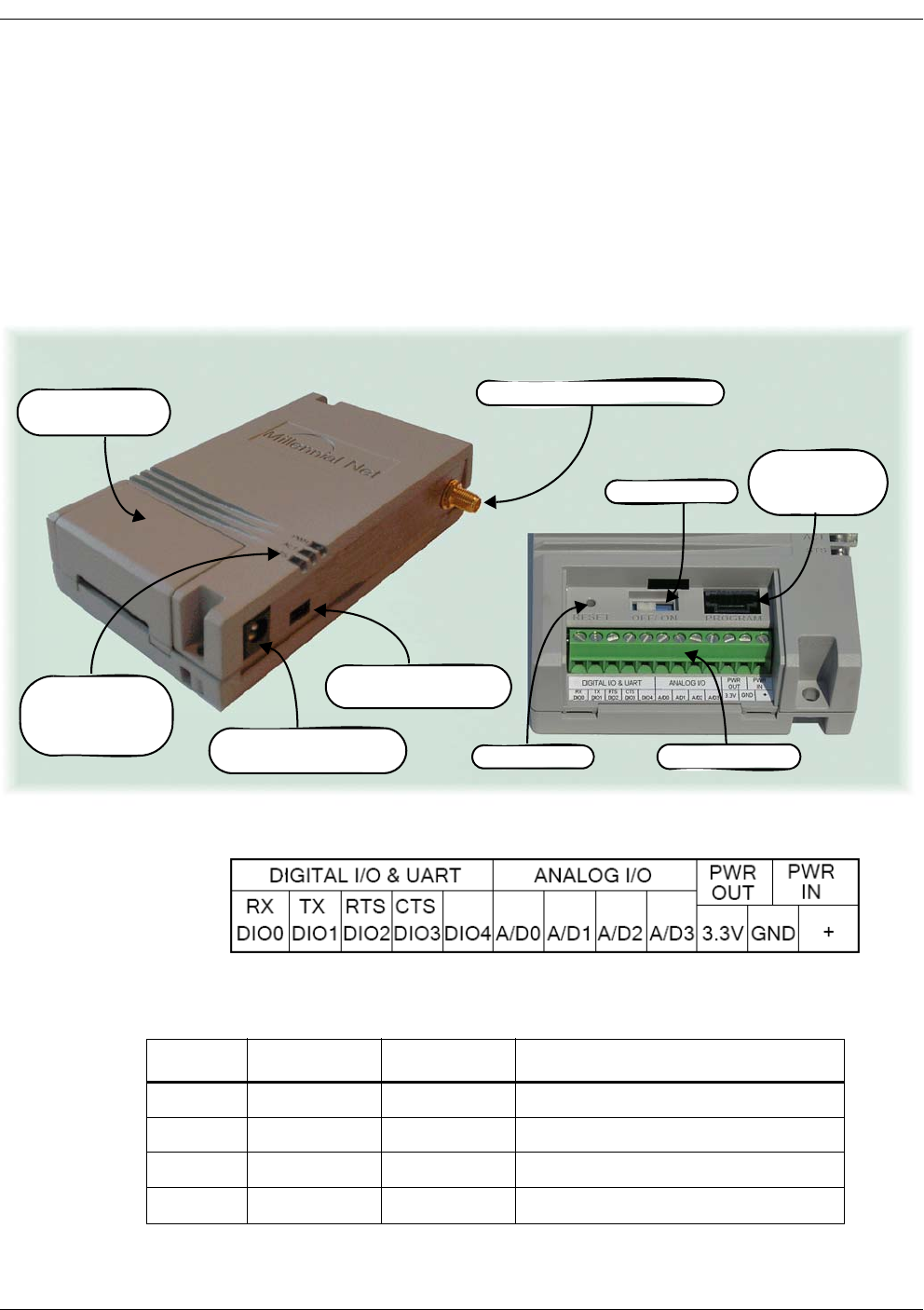
MeshGate Extra Long Range Setup (MG-5424XL)
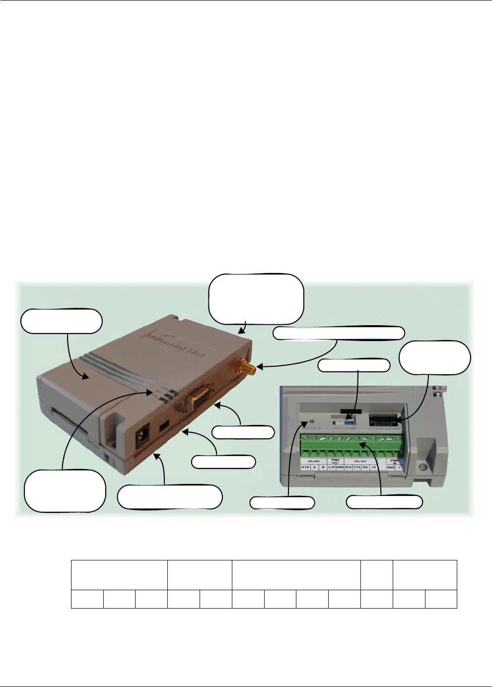
The MeshGate Extra Long Range, model number MG-5424XL (label with model number on
bottom), is shipped enclosed in a case that provides access to the antenna connector, RS-232
data port, console port, and power connectors as shown in Figure 2-8. Additionally, a lift-off
connector panel access cover on the case provides access to a 12-pin terminal block connector,
a reset button, an on/off switch, and a 6-pin external programming port.
Figure 2-8. MeshGate Extra Long Range components
The pin-out for the MeshGate Extra Long Range terminal block is as follows:
RS-485 PWR
OUT
RS-232 PWR
IN
RTN A B 3.3V GND RTS CTS RX TX GND +
RP-SMA Antenna Connector
Power Adapter
Connector
External
Programming
Port
Power LED
RF Activity LED
Status LED
RS-232 Port
Terminal Block
Product Label with:
- Model Number
- GroupID
- Device ID
Console Port
Connector Panel
Access Cover
Reset Button
On/Off Switch
Terminal Block

2-4 Millennial Net
Installing the MeshScape System
The function of each MeshGate terminal block pin is described as follows:
Mounting options
There are three mounting options for the MeshGate Extra Long Range:
• desktop
•wall
• DIN rail
Mounting the MeshGate Extra Long Range on a Desktop
1. Choose a level, stable surface on which to rest the MeshGate Extra Long Range.
2. Install one of the four supplied self-adhesive rubber feet in the round depression located
in each corner on the bottom of the MeshGate Extra Long Range chassis.
Mounting the MeshGate Extra Long Range on a Wall
When mounting the MeshGate Extra Long Range to a wall, we recommend that you secure the
MeshGate in place using two #6 screws and screw anchors (not supplied) of the appropriate
type for the mounting surface.
1. Place the MeshGate Extra Long Range against the wall in the desired mounting location.
2. Mark the location of the two chassis screw holes on the wall.
3. Drill two screw holes in to the wall at the marked locations.
Table 2-1. MeshGate terminal block pin assignments
Pin Label Input/Output Function
1RTN Reference Reference connection for RS-485
2 A I/O RS-485 signal +
3 B I/O RS-485 signal -
43.3V Output Power 3.3V output power
5GND Power Digital ground
6RTS Input RS-232 Request to Send
7CTS Output RS-232 Clear to Send
8RX Output RS-232 Receive Data
9 TX Input RS-232 Transmit Data
10 N/A N/A Not used
11 GND Power Digital Ground
12 +Power Input power (4.5V to 30V)
RK-5424-5 Reference Kit User’s Guide 2-5
Installing the Hardware
4. Mount the MeshGate Extra Long Range to the wall using two #6 screws (not supplied).
Mounting the MeshGate Extra Long Range to a DIN Rail
Millennial Net offers an optional DIN rail mounting kit (MG-DIN) to enable you to mount the
MeshGate to a standard DIN rail easily and quickly.
To mount the MeshGate Extra Long Range to a DIN rail using the supplied DIN rail mounting
bracket and hardware, refer to Figure 2-9 and complete the following steps:
Figure 2-9. Mounting the MeshGate Extra Long Range to a DIN rail
1. Using two of the supplied screws, secure the MeshGate Extra Long Range chassis to the
mounting bracket.
2. Mount the adapter bracket onto the DIN rail. Slide the adapter bracket’s clamp up and
then tighten its two screws to secure the adapter bracket in place on the DIN rail.
3. Using two of the supplied screws, secure the mounting bracket to the adapter bracket.
Connection options
The MeshGate Extra Long Range is equipped with an RS-232 serial port that enables the
MeshGate Extra Long Range to connect to a Windows XP host PC running the MeshScape
Network Monitor application, or to a Linux- or Windows-application platform (network
controller, PDA, PC, etc.) running a MeshScape API-based application.
Use one of the following options to establish a connection between the MeshScape Network
Monitor host PC and the MeshGate Extra Long Range:
• Establish a direct serial connection between the MeshScape Network Monitor host PC and
the MeshGate Extra Long Range using the supplied RS-232 cable.
Adapter Bracket
DIN Rail
Mounting Bracket
2-6 Millennial Net
Installing the MeshScape System
• Establish a TCP/IP connection from the Network Monitor host PC to a MeshScape Serial
Proxy Server that has a direct serial connection to the MeshGate Extra Long Range. The
MeshScape Serial Proxy Server that runs on a Linux or Windows XP host is supplied with
your MeshScape RK-5424-5 Reference Kit software. See page 2-20 for information about
installing and running the MeshScape Serial Proxy Server.
• Establish a TCP/IP connection from the Network Monitor host PC to an Ethernet-to-serial
adapter connected to the MeshGate Extra Long Range.
These MeshGate Extra Long Range connection options are described and depicted in the
following sections.
Regardless of which of the following serial connection options is used, the MeshScape Network
Monitor or other MeshScape API-based application can only access and monitor a single
MeshScape, i.e., a single instance of MeshScape Network Monitor cannot monitor multiple
MeshScapes.
Direct Serial Connection
Figure 2-10 shows a local direct serial connection between the MeshScape Network Monitor
host PC and the MeshGate Extra Long Range using the supplied RS-232 cable.
Figure 2-10. Direct serial connection to the MeshGate Extra Long Range
In this topology, only one MeshScape API-based application running on the host PC can access
the MeshScape.
TCP/IP Connection to a Serial Proxy Server
Figure 2-11 shows a MeshGate Extra Long Range connected to a PC running the MeshScape
Serial Proxy Server via the PC’s serial port.
RS-232 Cable
MeshGate Extra
Long Range
MeshScape Network Monitor
Host PC
RK-5424-5 Reference Kit User’s Guide 2-7
Installing the Hardware
A MeshScape API-based application functions as a serial proxy client by changing its lowest
level serial interface to a TCP/IP interface. The MeshScape API TCP/IP serial proxy client interface
opens a connection to the MeshScape Serial Proxy Server by connecting to its well advertised
port.
Local and remote MeshScape API-based applications including MeshScape Network Monitor
access the MeshScape data on the MeshGate Extra Long Range by connecting to the
MeshScape Serial Proxy Server at IP address 10.0.0.90 on port 45090.
Although Figure 2-11 does not show any MeshScape API-based applications running on the PC,
any number of MeshScape API-based applications could be running on the same PC host as the
MeshScape Serial Proxy Server. The MeshScape Serial Proxy Server supports up to ten client
connections.
Figure 2-11.Connection to the MeshGate via the MeshScape serial proxy server
MeshGate Extra
Long Range
MeshScape Network Monitor
MeshScape Network Monitor
MeshScape API-based
Application
MeshScape API-based
Application
Serial Proxy Server
10.0.0.90:45090

2-8 Millennial Net
Installing the MeshScape System
TCP/IP Connection to an Ethernet-to-serial Adapter
Figure 2-12 shows a MeshGate Extra Long Range connected to an Ethernet network using an
Ethernet-to-serial adapter. The Ethernet-to-serial adapter has both an RJ-45 Ethernet connector
and a DB-9 serial connector. The device accepts TCP/IP packetized serial data from the Ethernet,
extracts the raw data, and forwards it out the serial port. The reverse operation is performed in
the serial-to-Ethernet direction.
Local and remote MeshScape API-based applications including MeshScape Network Monitor
access the MeshScape data on the MeshGate Extra Long Range by connecting to the
MeshScape Serial Proxy Server at IP address 10.0.0.90 on port 2101.
Millennial Net has qualified the Digi One SP Ethernet-to-serial adapter for use with MeshScape
wireless mesh networks. Appendix C of this user’s guide presents a high-level configuration
procedure for the Digi One SP Ethernet-to-serial adapter when used to provide an Ethernet
connection for the MeshGate Extra Long Range.
RK-5424-5 Reference Kit User’s Guide 2-9
Installing the Hardware
Figure 2-12. Connection to the MeshGate via Ethernet-to-serial Adapter
Console Port
The MeshGate Console Port is a mini-serial connector that provides access to the MeshGate
command line interface (CLI). You can connect to the MeshGate CLI to verify and configure the
MeshGate serial port settings as described in Appendix , “Accessing the MeshGate CLI”.
Setup procedure
To set up the MeshGate Extra Long Range:
MeshScape Network Monitor
MeshScape Network Monitor
MeshScape API-based
Application
MeshScape API-based
Application
Ethernet-to-serial Adapter
10.0.0.90:2101
MeshGate Extra
Long Range

2-10 Millennial Net
Installing the MeshScape System
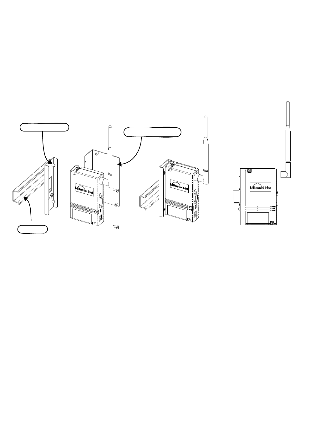
1. Attach one of the four included 1/2-wave antennas to the REV-SMA antenna connector.
The antenna screws onto the connector.
2. Establish a connection from the MeshScape Network Monitor to the MeshGate Extra
Long Range by completing one of the following:
– Connect the supplied RS-232 cable between the MeshGate’s RS-232 port and the
MeshScape Network Monitor host PC’s serial port.
– Connect the supplied RS-232 cable between the MeshGate’s RS-232 port and the
serial port on a PC running the MeshScape Serial Proxy Server. You can then
establish a remote TCP/IP connection from the MeshScape Network Monitor host
PC to the Serial Proxy Server. Installing and running the MeshScape Serial Proxy
Server is described on page 2-20.
– Connect the supplied RS-232 cable between the MeshGate’s RS-232 port and an
Ethernet-to-serial adapter (not supplied) connected to an Ethernet network. You
can then establish a remote TCP/IP connection from the MeshScape Network
Monitor to the Ethernet-to-serial adapter. Millennial Net has qualified the Digi One
SP Ethernet-to-serial adapter for use with MeshScape wireless mesh networks.
Appendix C of this user’s guide presents a high-level configuration procedure for
the Digi One SP Ethernet-to-serial adapter when used to provide an Ethernet
connection for the MeshGate Extra Long Range.
3. Plug the supplied AC adapter into the MeshGate Extra Long Range power connector and
then into a 110/220 VAC power source.
4. Remove the connector panel access cover and slide the on/off switch to the ON position.
5. Replace the connector panel access cover.
The MeshGate Extra Long Range is ready to interface with the host PC and surrounding
network nodes (Mesh Nodes and End Nodes). For information on the behavior of the
status LEDs, see Table 2-2.
MeshGate Extra Long Range status LED operation
Table 2-2 describes how the status LEDs on the MeshGate Extra Long Range behave.
Caution
When attaching the antenna, only hand-tighten the antenna to the
connector. Using excessive force may damage the connector.
Table 2-2. MeshGate Extra Long Range status LEDs
LED Led State Status
PWR On Connection with host device detected.
Blinking No host device detected or MeshScape Network Monitor not
running.
Off Power has been removed.

RK-5424-5 Reference Kit User’s Guide 2-11
Installing the Hardware
MeshGate Extra Long Range default settings
Table 2-3 lists the default settings for the MeshGate Extra Long Range gateway.
* Persisted indicates value is retained after power cycle.
ACT Flashing Gateway detects RF activity. The Activity LED will flash when
detecting valid packets (packets destined for device) and may also
flash when detecting invalid packets (packets destined for other
devices) or environmental noise. Only valid packets are processed
by the device.
Off No RF activity detected.
STS (Reserved for future use.)
Table 2-3. MeshGate Extra Long Range default Settings
Variable
Description Default Value Persisted?*
RS-232 Data Port Configuration RS232
115,200 baud
No parity
No hardware flow control
Yes
Console Port RS232
115,200 baud
No parity
No hardware flow control
Yes
Table 2-2. MeshGate Extra Long Range status LEDs
LED Led State Status
2-12 Millennial Net
Installing the MeshScape System
Mesh Node Setup (MN-5424)
The Mesh Nodes, model number MN-5424 (label with model number on bottom), are shipped
enclosed in cases that provide: RP-SMA antenna connector, three-position external power
source switch, and a connector for the supplied power adapter as shown in Figure 2-13.
Additionally, a lift-off connector panel access cover on the case provides access to a 12-pin
terminal block connector, a reset button, an on/off switch, and a six-pin external programming
port.
Figure 2-13. Mesh node components
The pin-out for the Mesh Node terminal block is as follows:
The function of each Mesh Node terminal block pin is described as follows:
Table 2-4. Mesh Node terminal block pin assignments
Pin Label Input/Output Function
1DIO0/RxD I/O or Output Digital Input/Output 0 or UART RX
2DIO1/TxD I/O or Input Digital Input/Output 1 or UART TX
3DIO2/RTS I/O or Input Digital Input/Output 2or UART RTS (in)
4DIO3/CTS I/O or Output Digital Input/Output 3 or UART CTS (out)
Connector Panel
Access Cover
RP-SMA Antenna Connector
External
Power Source Switch
External
Programming
Port
Power LED
RF Activity LED
Status LED Power Adapter
Connector Reset Button
On/Off Switch
Terminal Block