Millennial Net RT-5209Z1 Wireless Sensor Network Router User Manual BA Basys
Millennial Net Wireless Sensor Network Router BA Basys
Manual

Document Number: DOC-0004
Revision: 02
Released: July 2004
Building Automation
i-Bean® Wireless Sensor Network
User’s Guide

COPYRIGHT
This manual is produced and copyrighted by Millennial Net, Inc. Any use or reproduction of the contents of this
manual without the prior written consent of Millennial Net, Inc. is strictly prohibited.
NOTICE
All title and copyrights to this document are owned by Millennial Net, Inc. No part of the contents of this document
may be reproduced or transmitted in any form or by any means without the written permission of Millennial Net, Inc.
Millennial Net, Inc. shall not be liable for errors contained herein. Millennial Net, Inc. shall not be liable for any
damages whatsoever, including, without limitation, damages for loss of business profits, business interruption, loss
of business information, or other pecuniary loss arising out of the use of this documentation even if Millennial Net,
Inc. has been made aware of the possibility of such damages.
Information contained in this document is subject to change without notice. While every effort is made to ensure
that the information is accurate as of the publication date, users are reminded to update their use of this document
with documents published by Millennial Net, Inc. subsequent to this date.
Third-party product information is for informational purposes only, and constitutes neither an endorsement nor a
recommendation. Millennial Net, Inc. expressly disclaims any responsibility with respect to the performance of the
third-party products.
Copyright 2000, 2001, 2003, 2004 by Millennial Net, Inc.
ALL RIGHTS RESERVED
Printed in U.S.A.
Millennial Net, Inc.
24
th Avenue
Burlington, MA 01803-3304 USA
781.222.1030

Building Automation User’s Guide v
CAUTION
All device installation, configuration, and reconfiguration must be performed only by qualified service
personnel.
Initialization of the product should be performed only by a qualified systems administrator.
Compliance Statement
FCC compliance for Millennial Net’s Building Automation system consisting of the following
models/components:
• GS-5209Z1 Gateway Server
• RT-5209Z1 Sub-base Router
• RT-5209Z2 Standalone Router
Compliance Statement (Part 15.19)
The Millennial Net Building Automation system complies with Part 15 of the FCC Rules and with RSS-210 of
Industry Canada.
Operation is subject to the following two conditions:
(1) This device may not cause harmful interference, and
(2) This device must accept any interference received, including interference that may cause undesired
operation.
Warning (Part 15.21)
Changes or modifications not expressly approved by the party responsible for compliance could void the
user's authority to operate the equipment
Trademarks
© 2000, 2001, 2002, 2003, 2004 Millennial Net, Inc. All rights reserved. Millennial NetTM is a trademark and
i-Bean® is a registered trademark of Millennial Net. All other trademarks are the property of their respective
owners.
Information subject to change.

vi Building Automation User’s Guide

Building Automation User’s Guide vii
Table of Contents
About This Guide
Audience .................................................................................................................... xii
How to Use This Guide ............................................................................................... xii
Symbols and Conventions ...........................................................................................xiii
Contacting Millennial Net ...........................................................................................xiv
World Wide Web.................................................................................................. xiv
Customer Support ................................................................................................ xiv
Technical Publications........................................................................................... xiv
1 Network Overview
Product Overview........................................................................................................1-2
General Network Characteristics .................................................................................1-3
i-Bean Network Overview............................................................................................1-4
2i-Bean Network Hardware
Gateway Server...........................................................................................................2-2
Gateway Server Parts.......................................................................................... 2-2
Gateway Server Specifications ............................................................................ 2-3
Sub-base Router .........................................................................................................2-4
Sub-base Router Parts......................................................................................... 2-5
Sub-base Router Specifications ........................................................................... 2-5
Standalone Router ......................................................................................................2-6
Standalone Router Parts ..................................................................................... 2-6
Standalone Router Specifications ........................................................................ 2-6
Performance Considerations .......................................................................................2-8
General Installation Recommendations ............................................................... 2-8
Index

viii Building Automation User’s Guide

Building Automation User’s Guide ix
List of Figures
Figure 1-1. Millennial Net’s Building Automation Wireless Network................................ 1-2
Figure 1-2. i-Bean Network Topology............................................................................. 1-4
Figure 1-3. Sample i-Bean network topologies ............................................................... 1-5
Figure 2-1. Gateway Server and associated parts............................................................ 2-2
Figure 2-2. Sub-base Router........................................................................................... 2-4
Figure 2-3. Standalone Router ....................................................................................... 2-6

xBuilding Automation User’s Guide


xii Building Automation User’s Guide
Audience
This guide is intended for the following qualified service personnel who are responsible for
installing and operating the i-Bean Building Automation System:
• System installer
• Hardware technician
• System operator
How to Use This Guide
The sections of this guide provide the following information:
Section Provides
Chapter 1, “Network Overview” Overview of the Building Automation system and the
i-Bean network.
Chapter 2, “i-Bean Network Hardware” - Details of the i-Bean hardware: Gateway Server,
Sub-base Routers, and Standalone Routers.
- Specifications for each device is also listed here.
- Recommendations for implementing a wireless network.
Index An alphabetical index of topics described in this manual.
Note: For instructions on installing the i-Bean devices described in this guide, refer to the
Quick Start Guide for Building Automation (P/N DOC-0010).

Building Automation User’s Guide xiii
Symbols and Conventions
This guide uses the following symbols and conventions to emphasize certain information.
Blue text indicates a link to the item within the PDF file.
Italics - Indicate the first occurrence of a new term, book title, and emphasized text.
1. Numbered list - Where the order of the items is important.
• Bulleted list - Where the items are of equal importance and their order is unimportant.
Note: A note is used to highlight important information relating to the topic being
discussed.
Caution
A caution means that a specific action could cause harm to the equipment or to the data.
Warning
A warning describes an action that could result in physical injury, or destruction of
property.
Hazard
A hazard is a particular form of warning related expressly to electric shock.

xiv Building Automation User’s Guide
Contacting Millennial Net
World Wide Web
Millennial Net maintains a site on the World Wide Web where information on the company and
its products can be found. The URL is:
www.millennialnet.com
Customer Support
For answers to your technical questions, Millennial Net’s Customer Service department can be
reached at:
phone:
781.222.1030
e-mail:
support@millennialnet.com
Technical Publications
Millennial Net is committed to providing you with quality technical documentation. Your
feedback is valuable and appreciated. Please send comments, suggestions, and enhancements
regarding this guide or any Millennial Net documentation to:
support@millennialnet.com
Please include the document title, number, and version in your email.

1-2 Building Automation User’s Guide
Network Overview
Product Overview
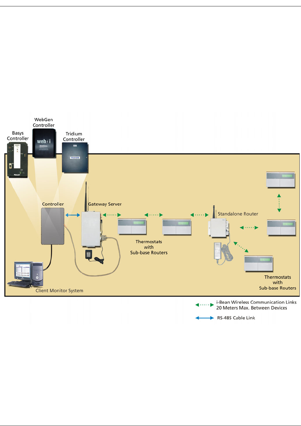
The Building Automation system uses Millennial Net's i-Bean® technology to allow monitoring
and configuring of building thermostats over a wireless network. When installed, the i-Bean
wireless network replaces the RS-485 bus typically used between the controller and the
associated thermostats, eliminating the need for running cables between devices. Millennial
Net's Gateway Server provides the interface between the controller and the Millennial Net
Sub-base Routers attached to each thermostat. Figure 1-1 provides a view of the various
components of the Building Automation system.
Figure 1-1. Millennial Net’s Building Automation Wireless Network
Client Monitor System
The client monitor system contains the third party Building Management System for
monitoring and control of the thermostats on the wireless network.
Controller
The controller is a data collection and storage device that is designed to communicate
directly with TCS/Basys Controls S-series microprocessor-based thermostats over an RS-485
cable. Millennial Net supports the following third party controller models:
• Basys Controller, model: QD2020ie

Building Automation User’s Guide 1-3
General Network Characteristics
• WebGen Controller, model: Web-i
• Tridium Controller, model: JACE-403
Gateway Server
Millennial Net’s Gateway Server translates messages from the controller’s RS-485 port to
Millennial Net packets for wireless transmission to a thermostat’s Sub-base Router and vice
versa. The Gateway Server also manages the wireless network.
Sub-base Router (mounted to back of thermostats)
Millennial Net’s Sub-base Router provides each thermostat with wireless communications.
The Sub-base Router converts data on the thermostat’s RS-485 line to/from Millennial Net
packets.
Standalone Router
Millennial Net’s Standalone Router is used in applications requiring increased distances
between Sub-base Routers, Sub-base Router(s) and the Gateway Server, or to circumvent
obstacles preventing good wireless communications.
General Network Characteristics
Characteristics of the Building Automation system include the following:
• Communication path: Messages are passed from i-Bean node to i-Bean node until they
reach their destination, extending the range and allowing for routing around obstacles.
Up to six intermediate i-Bean nodes (Sub-base Routers or Standalone Routers) can hop the
signal from source to destination.
•Range: Typically, 20 meters maximum between any of the i-Bean nodes. This value is
based on a same-floor application, in which all the devices are on one floor without any
obstacles between them. The actual distances between devices will vary depending on
environmental issues, such as the number of floors between devices, construction
material, etc.
•Number of thermostats: Up to seven thermostats and seven Sub-base Routers and/or
Standalone Routers can be used in a wireless network with one controller and one
Gateway Server.
•Polling rate: Typically, from two to three nodes (Sub-base Routers with attached
thermostats or Standalone Routers) per second, depending on network topology. A star
network topology, in which Sub-base Routers or Standalone Routers are only one or two
hops from the Gateway Server, supports a higher polling rate than a linear topology, in
which the furthest node is reached through several hops. For more information on
different network topologies, refer to ’i-Bean Network Overview’ on page 1-4.
•Radio frequency: i-Bean network nodes use the license-free 916 MHz band.
•FCC Compliance: All radio components are designed to be compliant with FCC 15.249.
1-4 Building Automation User’s Guide
Network Overview
i-Bean Network Overview
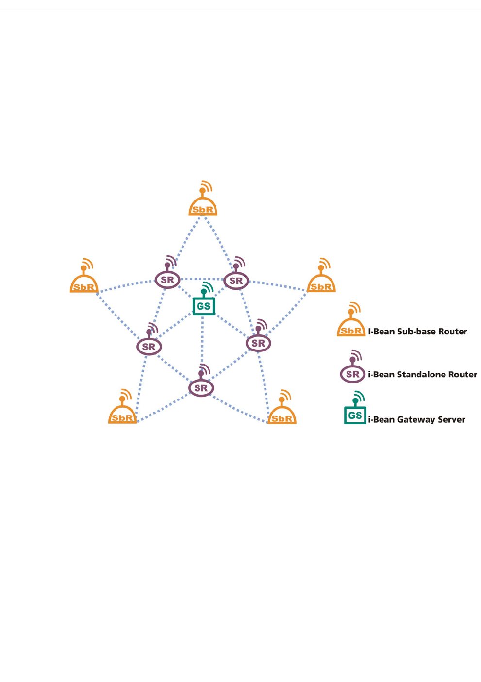
Millennial Net's innovative, self-organizing i-Bean network technology combines micro-power
sensor interface Sub-base Routers and Standalone Routers with a Gateway Server to form a
reliable, scalable Star Mesh wireless network (see Figure 1-2). This is a unique solution for low
data-rate networks that provides fault-tolerant networking. Our patent-pending network
protocol creates robust, fully redundant wireless links from the Gateway Server to the Sub-base
Routers and optional Standalone Routers through a self-configuring mesh network.
Figure 1-2. i-Bean Network Topology
Each i-Bean network device is configured at the factory with a unique device ID and a group ID.
The device ID indentifies the device within a network, while the group ID identifies the i-Bean
network that the device is associated with. Both IDs are statically assigned and cannot be
changed by a system user. The group ID allows i-Bean devices to establish networks within the
same location without interfering with each other. Sub-base Routers and Standalone Routers
can join the network only if they have the same group ID that is assigned to the Gateway
Server.
The i-Bean network devices self-organize at power-up and re-configure in response to changes
in the environment, network traffic, device status, and location. These devices enable mobility
and minimize installation and operating costs.
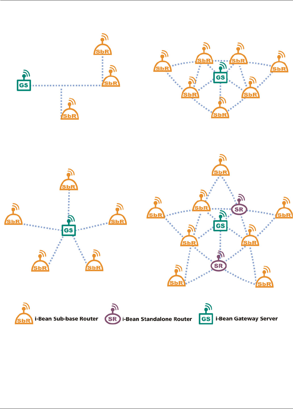
Figure 1-3 illustrates several different possible i-Bean wireless network topologies. Standalone
Routers are included randomly in the Star Mesh example to illustrate how they can be placed
where needed to increase the communication range between device hops or circumvent
obstacles.
Building Automation User’s Guide 1-5
i-Bean Network Overview
Figure 1-3. Sample i-Bean network topologies
Star Mesh
Providing high reliability
Simple Star
Providing multiple, linear paths from the
Sub-base Routers to the Gateway Server
Simple Mesh
Providing alternate paths from the
Sub-base Routers to the Gateway Server
Linear
Consisting of single path between Gateway Server
and Sub-base Routers

1-6 Building Automation User’s Guide
Network Overview

Building Automation User’s Guide 2-1
2
i-Bean Network Hardware
This chapter provides information on the parts associated with each i-Bean device and lists the
technical specifications of each device. Also included here is a section containing
recommendations for attaining optimal network performance.
• ’Gateway Server’ on page 2-2
• ’Sub-base Router’ on page 2-4
• ’Standalone Router’ on page 2-6
• ’Performance Considerations’ on page 2-8
2-2 Building Automation User’s Guide
i-Bean Network Hardware
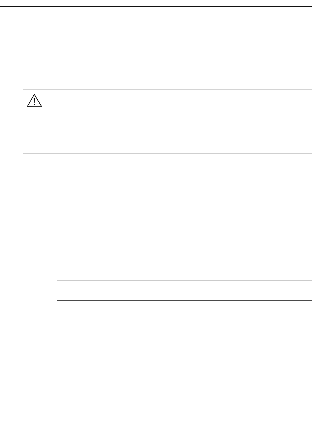
Gateway Server
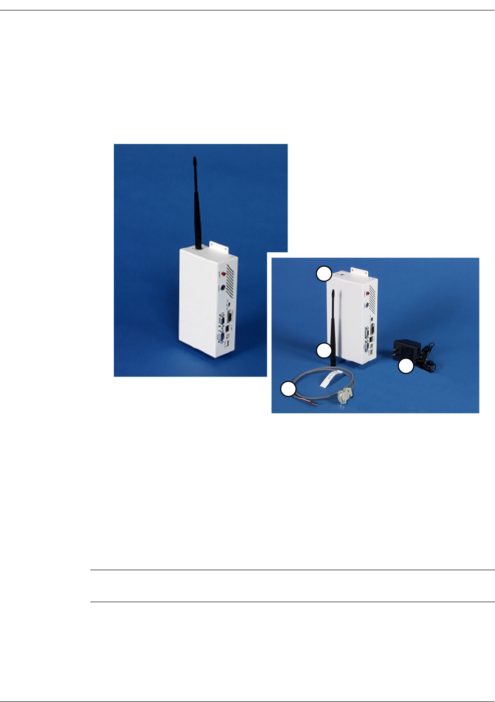
Shown in Figure 2-1, Millennial Net’s Gateway Server (model GS-5209Z1) translates messages
from a controller’s RS-485 port to Millennial Net packets for wireless transmission to
thermostats, and vice versa.
Figure 2-1. Gateway Server and associated parts
Gateway Server Parts
Referring to Figure 2-1, the Gateway Server assembly is shipped with the following items:
1. Gateway Server
2. Gateway Server antenna
3. RS-485 cable (DB-9 to tinned leads)
4. Wall plug-in regulated AC adapter (120 VAC to 12 VDC)
Note: For instructions on installing the Gateway Server, refer to the Quick Start Guide for
Building Automation (P/N DOC-0010).
1
2
3
4

Building Automation User’s Guide 2-3
Gateway Server
Gateway Server Specifications
Components
• RS-485 Network Port:
– DB-9 (female)
– Configured internally to 9600, 8, n, 1, no flow control
•Power:
– Jack for 12 VDC from external regulated AC adapter (included); OD 5.5 mm, ID 2.5
mm; outer connector is ground, inner is +12 V.
– Slide switch turns device off and on
• READY LED: Illuminates solid after the device initializes (approx. 1 minute)
Power Requirements
• Gateway Server: 12 VDC @ 250 mA (from regulated AC adapter)
• AC adapter: 120 VAC
Dimensions
• Height (without antenna): 9.0” (228 mm), including mounting flanges. Antenna extends
height: 7.3” (186 MM) above top of mounting flanges.
• Width: 4.6” (116 mm)
• Depth: 2.4” (60 mm)
Temperature Range
0–550 C, operating
2-4 Building Automation User’s Guide
i-Bean Network Hardware
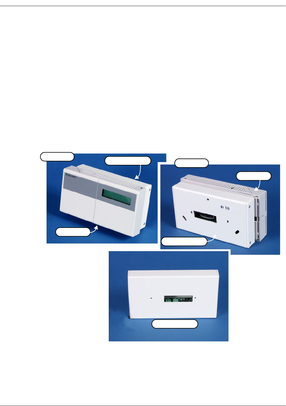
Sub-base Router
Shown in Figure 2-2, Millennial Net’s Sub-base Router (model RT-5209Z1) provides the
following functionality:
• Provides wireless communications for thermostats via unobtrusive add-on.
• Converts thermostat data on RS-485 line to/from wireless, transceiving in license-free
916 MHz ISM band.
• Fits between Basys model SZ1022 thermostat and wall.
• Accommodates mounting to wall or junction box.
• Passes wiring through the Sub-base Router to the thermostat.
• Powered by same 24 VAC source used by the thermostat.
Figure 2-2. Sub-base Router
Sub-base Router
Sub-base Router
Sub-base Router
Thermostat
Thermostat
Front View
Rear View

Building Automation User’s Guide 2-5
Sub-base Router
Sub-base Router Parts
Referring to Figure 2-2, the Sub-base Router is shipped with the following:
1. Sub-base Router
2. Screws (not shown) for mounting the Sub-base Router to the thermostat.
Sub-base Router Specifications
Components
• RS-485: Screw terminal strip for RS-485 + and RS-485 - connections.
• Power: Screw terminal strip for 24 VAC input (from thermostat)
• System LED:
– Device Online: Illuminates solid
– Device Offline: Blinks
Power Requirements
24 VAC @ 50 mA continuous
Dimensions
• Height: 3.7” (95 mm)
• Width: 6.7” (170 mm)
• Depth: 1.1” (28 mm)
Temperature Range
0–550 C, operating
Note: For instructions on installing the Sub-base Router, refer to the Quick Start Guide for
Building Automation (P/N DOC-0010).
2-6 Building Automation User’s Guide
i-Bean Network Hardware
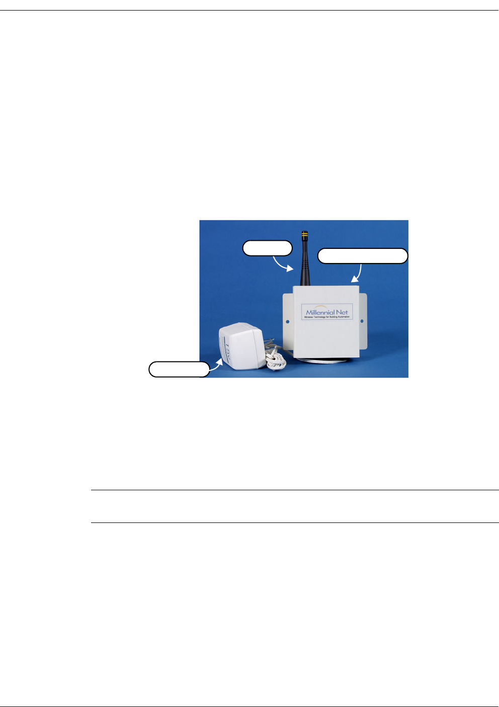
Standalone Router
Shown in Figure 2-3, Millennial Net’s Standalone Router (model RT-5209Z2) provides the
following functionality:
• Used as repeaters to:
– Extend the range between a Sub-base Router and the Gateway Server or between
Sub-base Routers.
– Circumvent communication path obstacles.
• May be mounted wherever needed and where 120 VAC power is available.
Figure 2-3. Standalone Router
Standalone Router Parts
Referring to Figure 2-3, the Standalone Router is shipped with the following:
1. Standalone Router with attached regulated AC adapter
2. Screw-on antenna
Standalone Router Specifications
Components
• Antenna jack
• Power: Attached regulated AC adapter
• Ready LED: Blinks once every several seconds to indicate communication with Gateway
Server
Note: For instructions on installing the Standalone Router, refer to the Quick Start Guide
for Building Automation (P/N DOC-0010).
AC Adapter
Standalone Router
Antenna

Building Automation User’s Guide 2-7
Standalone Router
Power Requirements
120 VAC, using attached plug-in regulated AC adapter
Dimensions
• Height: 3.7” (95 mm) plus 2.9” (74 mm) antenna height
• Width: 3.4” (87 mm), including mounting flanges
• Depth: 1.2” (31 mm)
Temperature Range
0–550 C, operating
2-8 Building Automation User’s Guide
i-Bean Network Hardware
Performance Considerations
Since the i-Bean wireless network uses radio waves to communicate between devices, there are
a number of items that need to be considered when implementing this type of network. This
section of the manual provides a number of suggestions that will ensure that your wireless
network will operate at its peak level of performance.
General Installation Recommendations
When installing the i-Bean wireless network devices, observe the following recommendations
when possible for optimal performance:
•Higher locations for i-Bean devices are generally better than lower locations. A
higher location usually provides a clear communication path over obstacles.
•Locate i-Bean devices at least one foot from metal shielding on all sides. Avoid
obstacles such as book shelves and file cabinets.
•Avoid sources of electrical noise, such as motors, pumps, and welding machines.
Locate i-Bean devices at least two feet from fluorescent fixtures.
•Avoid other devices using 900 MHz Industrial/Scientific/Medical (ISM) band. This
includes such items as cordless phones, intercoms, and walkie-talkies.
Warning
These electronic products are sensitive to electrostatic discharge (ESD).
Permanent damage to these devices can result if subjected to high energy
electrostatic discharges.
Proper precautions are recommended to avoid performance degradation or loss
of functionality.
Note: For instructions on installing the i-Bean devices, refer to the Quick Start Guide for
Building Automation (P/N DOC-0010).

Building Automation User’s Guide Index-1
Index
B
Basys Controller 1-2
Building Automation overview 1-2
C
client monitor system 1-2
communication path 1-3
controllers (supported) 1-2
E
ESD warning 2-8
F
FCC compliance 1-3
G
Gateway Server 1-3
overview 2-2
parts 2-2
specifications 2-3
general installation recommendations 2-8
I
i-Bean network overview 1-4
i-Bean network technology 1-2
N
network characteristics 1-3
network topologies 1-4
number of thermostats 1-3
P
performance considerations 2-8
polling rate 1-3
R
radio frequency 1-3
RS-485 bus 1-2
S
Standalone Router 1-3
overview 2-6
parts 2-6
specifications 2-6
Sub-base Router 1-3
overview 2-4
parts 2-5
specifications 2-5
T
Tridium Controller 1-3
W
WebGen Controller 1-3
wireless range 1-3

Index
Index-2 Building Automation User’s Guide