Millennial Net URM-G-916 Transmitter Module User Manual Manual
Millennial Net Transmitter Module Manual
Manual

Document Number: DOC-0051
Revision: 01
Released: August 2005
MeshScape™
Commercial- and Industrial-class
Wireless Sensor Networks
RK-5409-5 Reference Kit
for 916 MHz MeshScape Systems
User’s Guide

COPYRIGHT
This manual is produced and copyrighted by Millennial Net, Inc. Any use or reproduction of the contents of this
manual without the prior written consent of Millennial Net, Inc. is strictly prohibited.
NOTICE
All title and copyrights to this document are owned by Millennial Net, Inc. No part of the contents of this document
may be reproduced or transmitted in any form or by any means without the written permission of Millennial Net, Inc.
Millennial Net, Inc. shall not be liable for errors contained herein. Millennial Net, Inc. shall not be liable for any
damages whatsoever, including, without limitation, damages for loss of business profits, business interruption, loss
of business information, or other pecuniary loss arising out of the use of this documentation even if Millennial Net,
Inc. has been made aware of the possibility of such damages.
Information contained in this document is subject to change without notice. While every effort is made to ensure
that the information is accurate as of the publication date, users are reminded to update their use of this document
with documents published by Millennial Net, Inc. subsequent to this date.
Third-party product information is for informational purposes only, and constitutes neither an endorsement nor a
recommendation. Millennial Net, Inc. expressly disclaims any responsibility with respect to the performance of the
third-party products.
Copyright © 2000, 2001 - 2005 by Millennial Net, Inc.
ALL RIGHTS RESERVED
Printed in U.S.A.
Millennial Net, Inc.
2 Fourth Avenue
Burlington, MA 01803-3304 USA
+1 781.222.1030

RK-5409-5 Reference Kit User’s Guide v
CAUTION
Initialization of the product should be performed only by a qualified systems administrator.
Compliance Statements
FCC Compliance
FCC compliance for Millennial Net’s RK-5409-5 Reference Kit (916MHz, 5-3-1) consisting of the following
models/components:
• EN-5409 end node
• MN-5409 mesh node
• MG-5409 MeshGate gateway
Compliance Statement (Part 15.19)
The Millennial Net RK-5409-5 Reference Kit complies with Part 15 of the FCC Rules and with RSS-210 of
Industry Canada.
Operation is subject to the following two conditions:
(1) This device may not cause harmful interference, and
(2) This device must accept any interference received, including interference that may cause undesired
operation.
Warning (Part 15.21)
Changes or modifications not expressly approved by the party responsible for compliance could void the
user's authority to operate the equipment.
Unlicensed Modular Approval (for OEMs)
The URM-G-916 complies with the FCC's 47CFR Part 15 rules and regulations as well as Part 15 Unlicensed
Modular Approval as outlined in DA 00-1407. Compliance with the Modular Approval rules allows an OEM
to integrate the URM-G-916 into other products without further FCC certification of the intentional
radiator, but an OEM must still test their final product to comply with unintentional radiator requirements of
47CFCR Part 15.
Under the Modular Approval rules, an OEM must comply with the following when integrating the
URM-G-916 into an end product:
1. The OEM must ensure that FCC labeling requirements are met. This shall include a clearly visible label on
the exterior of the end product with the following nomenclature:
Contains FCC ID: R8N-URM-G-916
2. The OEM must only use the reverse-SMA antennas listed below when integrating the device into an end
product. These antennas have been tested and approved for use with the URM-G-916. Integrating the
module using any other antenna will require testing to ensure compliance with FCC rules and
regulations.
Mobile Mark ½ wave Antenna Part Number: PSKN3-925RS

vi Millennial Net
Nearson ½ wave Antenna Part Number: S467AH-915S
Linx ¼ wave Antenna Part Number: ANT-916-CW-QW
3. The OEM must use the same cable type and of the same length or longer than that defined below. Use
of another cable type or of a shorter length will require testing to ensure compliance with FCC rules and
regulations.
RF Cable type: RG174
RF Cable Length: 5.9" +/- 0.13”
Millennial Net Cable P/N: CBL-0008-01
Industry Canada Compliance Statement
This device has been designed to operate with an antenna having a maximum gain of 2.65 dB. Antenna
having a higher gain is strictly prohibited per regulations of Industry Canada. The required antenna
impedance is 50 Ohms.
To reduce potential radio interference to other users, the antenna type and its gain should be so chosen that
the equivalent isotropically radiated power (EIRP) is not more than that required for successful
communication.
OEM Integration
The module has the same requirements for integration into an OEM product for Industry Canada as it does
for FCC. The only difference being the labeling nomenclature required on the exterior of the OEM product.
The following must be clearly visible on the exterior of the OEM product:
Contains IC: 5127A-URMG916
Trademarks
© 2000 - 2005 Millennial Net, Inc. All rights reserved. Millennial Net™ and MeshScape™ are trademarks of
Millennial Net, Inc. All other trademarks are the property of their respective owners.
Information subject to change.

RK-5409-5 Reference Kit User’s Guide vii
Contents
About This Guide
Audience ....................................................................................................................xvi
Using This Guide .........................................................................................................xvi
Symbols and Conventions .......................................................................................... xvii
Contacting Millennial Net ......................................................................................... xviii
World Wide Web................................................................................................ xviii
Customer Support .............................................................................................. xviii
Technical Publications......................................................................................... xviii
Additional Resources .......................................................................................... xviii
1Introduction
Wireless Sensor Networking Overview.........................................................................1-2
Defining Wireless Sensors Networks ................................................................... 1-2
Wireless Sensor Network Components ............................................................... 1-3
MeshScape System Overview ......................................................................................1-6
Core Elements of MeshScape System.................................................................. 1-6
Data Models....................................................................................................... 1-7
Low-Power Configuration................................................................................... 1-9
The MeshScape RK-5409-5 Reference Kit..................................................................1-10
Major Features ................................................................................................. 1-11
Reference Kit Contents..................................................................................... 1-11
Host PC Requirements ...................................................................................... 1-12
2Installing the MeshScape System
Installing the MeshScape Wireless Sensor Network......................................................2-2
Installing the Hardware ...............................................................................................2-3
MeshGate Setup (MG-5409)............................................................................... 2-3
Mesh Node Setup (MN-5409) ............................................................................. 2-7
End Node Setup (EN-5409) ............................................................................... 2-12
Installing MeshScape Network Monitor ....................................................................2-14
Installing Contents of Millennial Net’s RK-5409 CD-ROM.................................. 2-14
Launching MeshScape Network Monitor Using Windows ................................. 2-15
3Running MeshScape Network Monitor
MeshScape Network Monitor Overview ......................................................................3-2
Menu Bar ........................................................................................................... 3-3
Gateway............................................................................................................. 3-4
Device Counts .................................................................................................... 3-4
Sensor Node Details............................................................................................ 3-4
Configuring a Node’s Operation .................................................................................3-6
Configuring Sample Interval of Single Node........................................................ 3-8
Configuring Sample Interval of all Network Nodes .............................................. 3-8
Configuring Digital I/O Operation ....................................................................... 3-9
Configuring UART Operation............................................................................ 3-12

viii Millennial Net
Configuring AD (analog-to-digital) Converter Operation.................................... 3-14
Configuring RS-232 Operation (MN-5409 only) ................................................. 3-15
Configuring RS-485 Operation (MN-5409 only) ................................................. 3-16
Using Watch Function to Display Configuration Information.............................. 3-17
Labeling an End Node or Mesh Node ........................................................................3-19
Configuring Persistence Attributes ............................................................................3-20
Selecting a Com Port on the Host PC ........................................................................3-21
Configuring Serial and ADC Data Formats ................................................................3-22
Turning Event Tracking On/Off..................................................................................3-23
Broadcasting Data to All Nodes.................................................................................3-24
Creating an Event Log File ........................................................................................3-26
Viewing the Contents of an Event Log File ................................................................3-27
Viewing MeshScape Statistics ...................................................................................3-29
4Using the MeshScape API
Using the MeshScape API ...........................................................................................4-2
MeshScape API Directory Structure .............................................................................4-3
MeshScape API Functions Overview ............................................................................4-5
iBeanAPI.h ..................................................................................................................4-7
Data Structures ................................................................................................... 4-7
Functions .......................................................................................................... 4-13
iBeanAPI_IO.h ...........................................................................................................4-23
Data Structures ................................................................................................. 4-23
Functions .......................................................................................................... 4-25
iBeanAPI_Utils.h........................................................................................................4-32
Functions .......................................................................................................... 4-32
iBeanAPI_LPR.h.........................................................................................................4-36
Functions .......................................................................................................... 4-36
iBeanAPI_performance.h...........................................................................................4-39
Data Structures ................................................................................................. 4-39
Functions .......................................................................................................... 4-41
Example API Code ....................................................................................................4-42
ListDevicesVC7 Example .................................................................................... 4-42
ListDevicesVC7 Code......................................................................................... 4-43
ASample Application
Application Overview................................................................................................. A-2
Application Components.................................................................................... A-3
Application Setup & Operation .................................................................................. A-4
Temperature Sensor Assembly Setup .................................................................. A-4
Launching TempMonitor Application.................................................................. A-5
TempMonitor Overview...................................................................................... A-6
Changing Temperature Sensor Battery ....................................................................... A-7
BPerforming Firmware Upgrades and
Configuring Device IDs
Getting Started with MeshScape Programmer.............................................................B-2
Connecting the Target Device to Your Computer ................................................ B-2
Launching MeshScape Programmer Using Windows............................................ B-3

RK-5409-5 Reference Kit User’s Guide ix
Performing MeshScape Programmer Operations......................................................... B-4
Upgrading Firmware on the Target Device .......................................................... B-4
Unlocking Features on the Target Device ............................................................ B-5
Reprogramming the Group and Device IDs on the Target Device......................... B-6
Getting Started with End Node Configurator.............................................................. B-8
Connecting the Target End Node to Your Computer .......................................... B-8
Launching End Node Configurator Using Windows............................................. B-9
Performing End Node Configurator Operations ........................................................ B-10
Glossary
Index

xMillennial Net

RK-5409-5 Reference Kit User’s Guide xi
Figures
Figure 1-1. Untethered, mobile ad hoc network nodes................................................... 1-2
Figure 1-2. Basic wireless sensor network components................................................... 1-4
Figure 1-3. Adding a mesh node module ....................................................................... 1-4
Figure 1-4. MeshScape system core elements................................................................. 1-6
Figure 2-5. MeshGate components ................................................................................ 2-3
Figure 2-6. Mounting the MeshGate to a DIN rail........................................................... 2-5
Figure 2-7. Mesh node components............................................................................... 2-7
Figure 2-8. Installing mesh node battery pack .............................................................. 2-10
Figure 2-9. Mesh node components............................................................................. 2-11
Figure 2-10. End node and terminal board (top and bottom views) ................................ 2-12
Figure 2-11. Using Windows’ Start menu to launch MeshScape Network Monitor ......... 2-15
Figure 3-12. Sample MeshScape Network Monitor window ............................................. 3-2
Figure 3-13. MeshScape Network Monitor’s Device window ............................................ 3-6
Figure 3-14. Configuring sample interval of single node................................................... 3-8
Figure 3-15. Configuring sample interval of all nodes....................................................... 3-9
Figure 3-16. Configuring end node or mesh node for digital I/O .................................... 3-11
Figure 3-17. Configuring end node or mesh node for UART operation........................... 3-13
Figure 3-18. Configuring end node/mesh node for analog I/O........................................ 3-14
Figure 3-19. Configuring mesh node for RS-232 ............................................................ 3-15
Figure 3-20. Configuring mesh node for RS-485 ............................................................ 3-16
Figure 3-21. Displaying I/O information using Watch function........................................ 3-17
Figure 3-22. Labeling an end node or mesh node .......................................................... 3-19
Figure 3-23. Configuring node persistence attributes ..................................................... 3-20
Figure 3-24. Selecting com port on host PC ................................................................... 3-21
Figure 3-25. Configuring serial and ADC data formats ................................................... 3-22
Figure 3-26. Turning device event tracking on/off .......................................................... 3-23
Figure 3-27. Broadcasting data to all nodes ................................................................... 3-25
Figure 3-28. Configure an event log file......................................................................... 3-26
Figure 3-29. View contents of event log file ................................................................... 3-27
Figure 3-30. Viewing MeshScape statistics ..................................................................... 3-30
Figure 4-1. Using the MeshScape API............................................................................. 4-2
Figure 4-2. MeshScape API directories............................................................................ 4-3
Figure A-2. API example: ListDevicesVC7 ...................................................................... 4-42
Figure A-1. Temperature sensor assembly overview (cover removed) .............................. A-2
Figure A-2. Process flow................................................................................................. A-3
Figure A-3. Installing end node in temperature sensor assembly ..................................... A-4
Figure A-4. Launching TempMonitor .............................................................................. A-5
Figure A-5. TempMonitor display ................................................................................... A-6
Figure A-6. Changing temperature sensor assembly battery ........................................... A-7
Figure B-1. Connecting MeshGate programming cable w/adapter to mesh node ........... B-3
Figure B-2. The MeshScape Programmer main window.................................................. B-4
Figure B-3. Connecting an end node to the programming terminal board...................... B-8
Figure B-4. The End Node Configurator main window ................................................. B-10

xii Millennial Net

RK-5409-5 Reference Kit User’s Guide xiii
Tables
Table 2-1. MeshGate status LEDs ................................................................................... 2-5
Table 2-2. MeshGate default Settings ............................................................................ 2-6
Table 2-3. Mesh node status LEDs.................................................................................. 2-8
Table 2-4. MeshScape mesh node default settings ......................................................... 2-8
Table 2-5. MeshScape end node default settings ......................................................... 2-13
Table 3-6. Device window functions .............................................................................. 3-6
Table 3-7. Watch window functions ............................................................................ 3-17
Table 3-8. Event log key definitions.............................................................................. 3-27
Table 4-1. MeshScape API functions.............................................................................. 4-5

xiv Millennial Net


xvi Millennial Net
Audience
This guide is intended for the following qualified service personnel who are responsible for
installing, operating, and developing software to interface with the RK-5409-5 MeshScape
Wireless Sensor Network Reference Kit:
• System installer
• Hardware technician
• System operator
• System administrator
• Software developer
Using This Guide
The sections of this guide provide the following information:
Section Provides
Chapter 1, “Introduction” General overview of wireless sensor networking and the
MeshScape™ system.
Chapter 2, “Installing the MeshScape
System”
Instructions for installing the components of the
RK-5409-5 MeshScape Wireless Sensor Network
Reference Kit (MeshGate, mesh nodes, end nodes) and
MeshScape Network Monitor (GUI).
Chapter 3, “Running MeshScape
Network Monitor”
Procedures for using MeshScape Network Monitor
software to configure the MeshScape System nodes. Also
includes information for attaching external I/O devices to
an end node or mesh node.
Chapter 4, “Using the MeshScape API” Information on the MeshScape API functions.
Appendix A, “Sample Application” Procedure for running the sample application provided
with the reference kit.
Appendix B, “Performing Firmware
Upgrades and Configuring Device IDs”
Instructions for upgrading the firmware on MeshScape
devices and reprogramming the group and device IDs.
Glossary Defines terminology associated with wireless sensor
networking and the MeshScape system.
Index An alphabetical index of topics described in this manual.
RK-5409-5 Reference Kit User’s Guide xvii
Symbols and Conventions
This guide uses the following symbols and conventions to emphasize certain information.
Italics - Indicate the first occurrence of a new term, book title, and emphasized text.
1. Numbered list - Where the order of the items is important.
• Bulleted list - Where the items are of equal importance and their order is unimportant.
Note: A note is used to highlight important information relating to the topic being
discussed.
Caution
A caution means that a specific action could cause harm to the equipment or to the
data.
Warning
A warning describes an action that could result in physical injury, or
destruction of property.
Hazard
A hazard is a particular form of warning related expressly to electric shock.

xviii Millennial Net
Contacting Millennial Net
World Wide Web
Millennial Net maintains a site on the World Wide Web where information on the company and
its products can be found. The URL is:
www.millennialnet.com
Customer Support
For answers to your technical questions, Millennial Net’s Customer Service department can be
reached at:
phone:
+1 781.222.1030
e-mail:
support@millennialnet.com
Technical Publications
Millennial Net is committed to providing you with quality technical documentation. Your
feedback is valuable and appreciated. Please send comments, suggestions, and enhancements
regarding this guide or any Millennial Net documentation to:
support@millennialnet.com
Please include the document title, number, and version in your email.
Additional Resources
To obtain additional resources and information about wireless sensor networking and the
development and deployment of MeshScape-based applications, visit the resources page on our
Web site at:
www.millennialnet.com/resources
There you will find links to:
• Application notes
• Articles
• Brochures and data sheets
• Case studies
• Industry notes
• Source book
• White papers

RK-5409-5 Reference Kit User’s Guide 1-1
1
Introduction
This chapter provides an overview of the MeshScape system and Reference Kit. In this chapter
you will find:
•’Wireless Sensor Networking Overview’ on page 1-2
•’MeshScape System Overview’ on page 1-6
•’The MeshScape RK-5409-5 Reference Kit’ on page 1-10
1-2 Millennial Net
Introduction
Wireless Sensor Networking Overview
This section provides you with a basic understanding of wireless sensor network concepts and
components.
Defining Wireless Sensors Networks
Until recently, networks designed for monitoring and controlling sensors or actuators on a
network were limited in application and scope due to a major network design
consideration—the cables required to connect the various sensors and actuators to a
centralized collection point. In addition to the costs associated with installing and maintaining
communication cables (fiber optic or copper), this type of network infrastructure prevents
sensor mobility and severely limits the feasible applications of such a network.
Thanks to significant advances in low-power radio and digital circuit design, self-organizing
wireless sensor networks are now a reality. Sensors of all types (temperature, motion,
occupancy, vibration, etc.) can now be wirelessly enabled and deployed inexpensively and
quickly.
Wireless sensor networks fundamentally change the economics of deploying and operating a
sensor network, unlocking opportunities to achieve new efficiencies in production processes,
building control, or monitoring, to name just a few. Wireless sensor networks also enable the
development of a brand new class of applications and services not previously possible with
wired sensor networks.
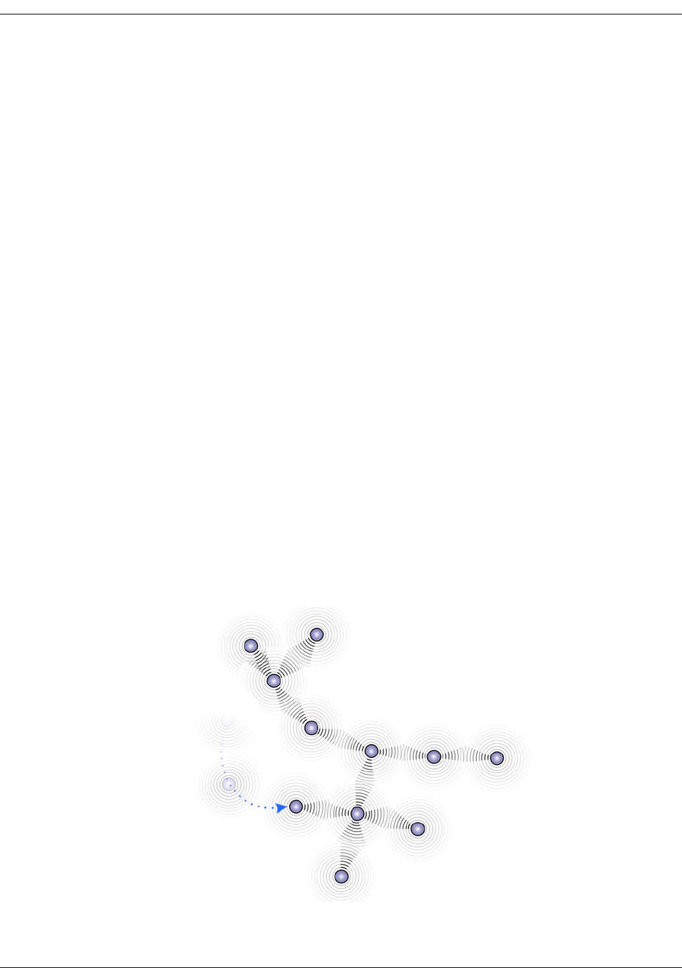
As illustrated in Figure 1-1, wireless sensor networks form what is called a wireless ad hoc
network, which refers to a network’s ability to self-organize and self-heal. This means there are
no administrative duties associated with establishing and maintaining a wireless sensor
network. By comparison, a wired infrastructure network, such as the LAN found in most office
environments, requires a significant amount of overhead to install and maintain in terms of
cabling and administrative time.
Figure 1-1. Untethered, mobile ad hoc network nodes
Mobile network node

RK-5409-5 Reference Kit User’s Guide 1-3
Wireless Sensor Networking Overview
In an ad hoc network, sensor nodes consisting of a sensor attached to a wireless module can be
randomly placed and moved as needed. If the network needs to scale up, additional sensor
nodes are easily added. The new sensor nodes and surrounding network will do the work of
discovering each other and establishing communication paths through single- and multi-hop
paths. All this is made possible through the use of robust, efficient network protocols
developed specifically for wireless sensor networks.
Wireless Sensor Network Components
This section describes the software and hardware that comprise a wireless sensor network.
System Software
The software required to integrate and operate a wireless sensor network resides as firmware in
the system modules and in the application platform as a set of API functions or network
monitoring system (NMS).
Module Firmware
Module firmware is a small, efficient piece of code that incorporates the module into a larger
ad hoc network. It “drives” the module's operation as part of the larger ad hoc network.
The firmware is also responsible for packaging the analog and digital sensor data into digital
packets and delivering them across the wireless sensor network.
API
An API, or application programming interface, is a set of commonly used functions for
streamlining application development. Used by application developers, an API provides hooks to
integrate the application platforms with the modules on the wireless sensor network.
API functions are grouped into “libraries.” In wireless sensor networks, there are two different
API libraries:
• High-level library: These functions are used to integrate the application with the gateway
module.
• Low-level library: These functions are used to integrate the sensor/actuator with the end
node module.
Network Monitoring System
A network monitoring system (NMS) is software used to interface with a particular wireless
sensor network, eliminating the need for any programming. Through the NMS’s graphical user
interface (GUI), network operators are able to see the various nodes of their wireless sensor
network. Depending on the type of network, control commands can also be issued through the
NMS. For example, a pin on a digital interface between an end node and an actuator can be set
to high to change the state of the actuator.
1-4 Millennial Net
Introduction
System Modules
The modules of a wireless sensor network enable wireless connectivity within the network,
connecting an application platform at one end of the network with one or more sensor or
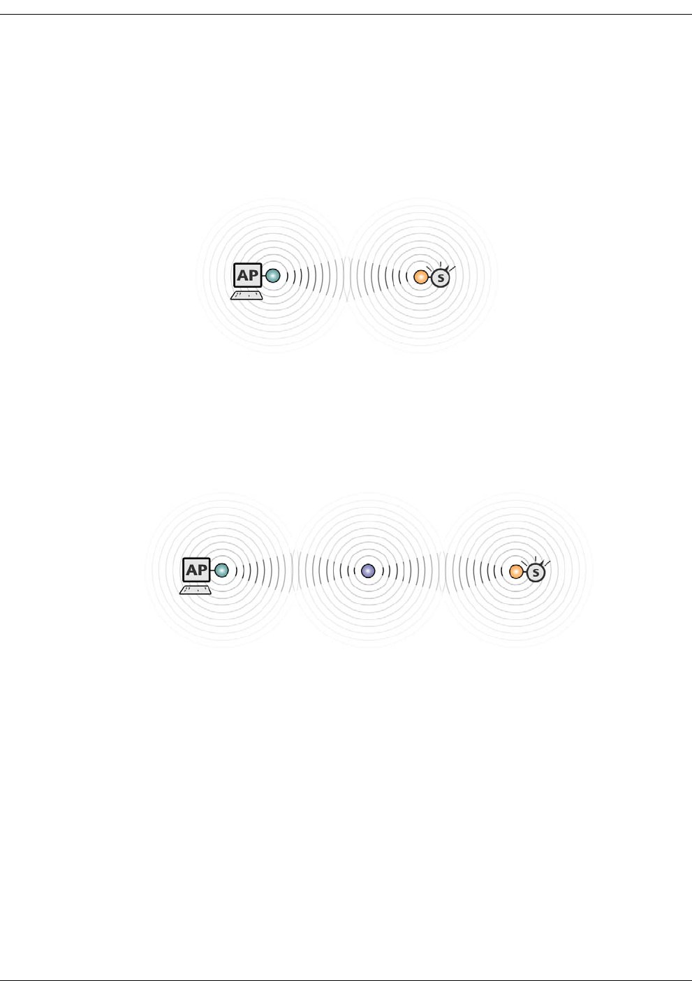
actuator devices at the other end. As shown in Figure 1-2, the gateway and end node modules
create a transparent, wireless data path between the application platform and sensor.
Figure 1-2. Basic wireless sensor network components
Exchange of analog or digital information between an application platform and one or more
sensor nodes takes place in a wireless fashion. In this example, the data path between the
gateway and end node is referred to as a single-hop network link.
To extend the range of a network or circumvent an obstacle, a wireless mesh node module can
be added between a gateway and an end node as shown in Figure 1-3.
Figure 1-3. Adding a mesh node module
This particular example represents a multi-hop data path, in which data packets are handed off
from one module to the next before reaching their destination (gateway-to-mesh node-to-end
node and vice versa).
More elaborate network layouts are discussed later in Network Topologies,” but for now, we’ll
take a closer look at each of the network components shown in Figure 1-3.
Application Platform
This is the network device (Network Controller, PC, handheld, etc.) used to monitor and control
the actions of the various sensors and actuators that are connected to the wireless sensor
network. The application platform is capable of making decisions based on the information it
gathers from the network. Typically, the wireless sensor network will come with an API and/or a
GUI used to interface with the wireless modules.

RK-5409-5 Reference Kit User’s Guide 1-5
Wireless Sensor Networking Overview
Gateway
The gateway is the interface between the application platform and the wireless nodes on the
network. The gateway can be a discrete module, or it can be integrated onto a Flash card form
factor for a handheld device, for example. All information received from the various network
nodes is aggregated by the gateway and forwarded on to the application platform. In the
reverse direction, when a command is issued by the application program to a network node,
the gateway relays the information to the wireless sensor network. The gateway can also
perform protocol conversion to enable the wireless network to work with other
industry-standard network protocols.
Mesh Node Module
Considered full-function devices (FFD), mesh node modules (sometimes called routers) are used
to extend network coverage area, route around obstacles, and provide back-up routes in case
of network congestion or device failure. In some cases, mesh nodes may also be connected via
analog and digital interfaces to sensors and actuators, providing the same I/O functionality of
an end node module. Mesh nodes can be battery powered or line powered.
End Node Module
Considered reduced-function devices (RFD), end nodes (sometimes called endpoints) provide
the physical interface between the wireless sensor network and the sensor or actuator to which
it is wired. End nodes will usually have one or more I/O connections for connecting to and
communicating with analog or digital sensor or actuator devices. End nodes are typically battery
powered.
Sensor/Actuator
These are the devices you ultimately wish to monitor and/or control. An example is a sensor
monitoring the pressure in an oil pipeline.
1-6 Millennial Net
Introduction
MeshScape System Overview
In order to realize benefits wireless sensor networking promises, the technology must be able to
address several critical requirements: reliability of data transmission, responsiveness to adapt to
dynamic environments, power efficiency, and scalability. The MeshScape™ wireless sensor
networking system from Millennial Net delivers on all of these requirements. The MeshScape
ready-to-embed hardware modules and assemblies support fast and cost-effective application
development.
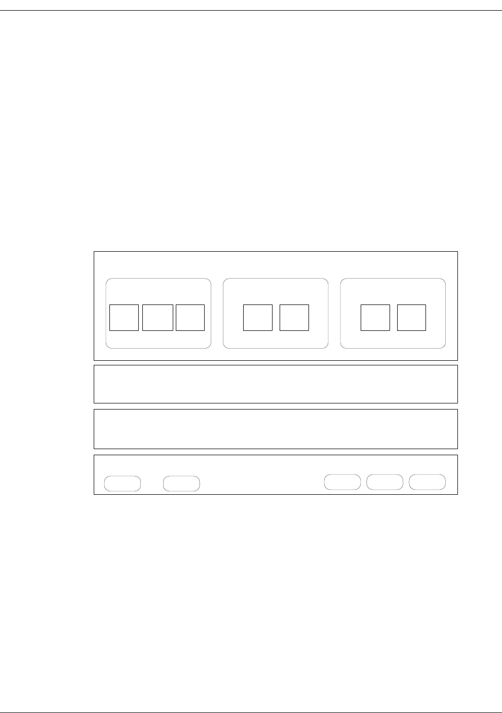
Core Elements of MeshScape System
The core elements of the MeshScape wireless sensor networking system are depicted in
Figure 1-4 below.
Figure 1-4. MeshScape system core elements
MeshScape Networking Software
The ultra-efficient, highly scalable, self-organizing networking software is based on Persistent
Dynamic Routing™ techniques. The networking software is delivered on the hardware modules
described in this section. For volume applications, the MeshScape system software can also be
licensed and integrated directly onto your sensor assembly.
Millennial Net has developed and optimized its protocol to address the unique characteristics
and challenges associated with wireless sensor networking. The end result is a networking
system and associated protocol that is highly scalable, ultra-efficient, and extremely responsive
and resilient in dynamic environments. The MeshScape protocol for wireless sensor networks
provides the industry's longest battery life at sensor nodes while delivering data over
fault-tolerant links with end-to-end redundancy. The Millennial Net protocol is based on a set of
Data Models
Collect Broadcast Dialog
Event
Driven Periodic
Sampling Store &
Forward Burst Stream Polling On
Demand
Network Monitor Application APIs
MeshScape Networking Software
w/ Persistent Dynamic Routing™
Hardware
ISM Bands
916 MHz. 2.4 Ghz
Modules
End Nodes Mesh
Nodes Gateways

RK-5409-5 Reference Kit User’s Guide 1-7
MeshScape System Overview
techniques including, Persistent Dynamic Routing for reliable and scalable wireless sensor
networks. When forming an ad hoc sensor network, Persistent Dynamic Routing requires
minimal overhead for requesting and establishing connectivity without relying on the
bandwidth-consuming flooding technique.
MeshScape Network Monitor and Application APIs
The MeshScape system delivers the tools to view and control network dynamics. The
MeshScape Network Monitor provides functions for monitoring and managing the network.
Application APIs streamline development by providing input/output functions for sensor and
application integration.
Hardware
The MeshScape system includes field-proven, “integratable” modules for fastest time to
market. These ready-to-integrate end nodes, mesh nodes, and gateways support numerous
application requirements and support various ISM bands for license-free operation around the
world.
Data Models
The MeshScape system provides built-in support for data movement profiles to speed
development including:
• data collection models
• bi-directional dialogue models
•broadcast models
These data models optimize the network for an application’s specific data requirements and
support a variety of classes for collection and bi-directional dialogue data models.
Data Collection Models
Data collection models describe monitoring applications where the data flows primarily from
the sensor node to the gateway. The MeshScape system supports the data collection models
described in this section.
Periodic Sampling
For applications where certain conditions or processes need to be monitored constantly, such as
the temperature in a conditioned space or pressure in a process pipeline, sensor data is acquired
from a number of remote sensor nodes and forwarded to the gateway or data collection center
on a periodic basis.
The sampling period mainly depends on how fast the condition or process varies and what
intrinsic characteristics need to be captured. In many cases, the dynamics of the condition or
process to be monitored can slow down or speed up from time to time. Therefore, if the sensor
node can adapt its sampling rates to the changing dynamics of the condition or process,
over-sampling can be minimized and power efficiency of the overall network system can be
further improved.

1-8 Millennial Net
Introduction
Another critical design issue associated with periodic sampling applications is the phase relation
among multiple sensor nodes. If two sensor nodes operate with identical or similar sampling
rates, collisions between packets from the two nodes is likely to happen repeatedly. It is
essential that sensor nodes can detect this repeated collision and introduce a phase shift
between the two transmission sequences in order to avoid further collisions resulting in optimal
network operation and minimized power usage.
Event Driven
There are many cases that require monitoring one or more crucial variables immediately
following a specific event or condition. Common examples include fire alarms, door and
window sensors, or instruments that are user activated. To support event-driven operations
with adequate power efficiency and speed of response, the sensor node must be designed such
that its power consumption is minimal in the absence of any triggering event, and the wake-up
time is relatively short when the specific event or condition occurs. Many applications require a
combination of event driven data collection and periodic sampling.
Store and Forward
In many applications, data can be captured and stored or even processed by a sensor node
before it is transmitted to the gateway or base station. Instead of immediately transmitting
every data unit as it is acquired, aggregating and processing data by remote sensor nodes can
potentially improve overall network performance in both power consumption and bandwidth
efficiency. One example of a store-and-forward application is cold-chain management where
the temperature in a freight container carrying produce or pharmaceuticals, for instance, is
captured and stored; when the shipment is received, the temperature readings from the trip are
downloaded and viewed to ensure that the temperature and humidity stayed within the desired
range.
Bi-Directional Dialogue Data Models
Bi-directional dialogue data models are characterized by a need for two-way communication
between the sensor/actuator nodes and gateway/application. The MeshScape system supports
the bi-directional dialogue data models described in this section.
Polling
Controller-based applications, such as those found in building automation systems, use a
polling data model. In this model, there is an initial device discovery process that associates a
device ID with each physical device in the network. The controller then polls each device on the
network successively, typically by sending a serial query message and waiting for a response to
that message. For example, an energy management application would use a polling data model
to enable the application controllers to poll thermostats, variable air volume (VAV) sensors, and
other devices for temperature and other readings.
On-Demand
The on-demand data model supports highly mobile nodes in the network where a gateway
device enters the network, automatically binds to that network and gathers data, then leaves
the network. With this model, one mobile gateway can bind to multiple networks and multiple
mobile gateways can bind to a given network. An example of an application using the

RK-5409-5 Reference Kit User’s Guide 1-9
MeshScape System Overview
on-demand data model is a medical monitoring application where patients in a hospital wear
sensors to monitor vital signs and doctors access that data via a PDA that is a mobile gateway. A
doctor enters a room and the mobile PDA automatically binds with the network associated with
that patient and downloads vital sensor data. When the doctor enters a second patient's room,
the PDA automatically binds with that network and downloads the second patient's data.
Broadcast Data Models
Broadcast data models are characterized by a need for one-to-many communication between
the gateway/application and sensor/actuator nodes. The MeshScape system supports the
broadcast data models described in this section.
Burst
The burst data model is characterized by an uneven pattern of data transmission from the
gateway/application to all sensor/actuator nodes on the wireless sensor network. The burst data
model has been used with industrial lighting applications.
Stream
In the stream data model, the gateway/application sends data in a continuous stream to all
sensor/actuator nodes on the wireless sensor network. The transport service guarantees that all
data is delivered to the other end in the same order as sent and without duplicates. The stream
data model is used when performing network upgrades.
Low-Power Configuration
Many sensors are dispersed over a wide area and must rely on batteries or solar cells for their
power source. Consider the example of sensors taking measurements on a gas pad, it would be
prohibitively expensive to network these sensors using cables, so a wireless sensor network is
the perfect solution. However, to be useful in such an environment, the wireless sensor network
must posses the following characteristics:
• Power: Low power consumption—sensor and node must be able to operate 10+ years on
a singe battery
• Scalability: End nodes must be able to scale as sensor counts increase.
• Data Rate: Application/gateway must support a configurable sample rate.
• Range: End nodes must be able to communicate over distances of 60 to 80 feet and Mesh
nodes must be able to communicate at distances up to 100 feet.
• Integration: The end nodes must be integrated with the sensor.
The MeshScape system possesses all of theses characteristics and uses configurable sleep and
duty cycle intervals to minimize power consumption.

1-10 Millennial Net
Introduction
The MeshScape RK-5409-5 Reference Kit
Millennial Net's RK-5409-5 Reference Kit contains everything you need to set up a
self-organizing, wireless star-mesh network. Once installed, you are able to observe the
performance and operation of the network components and prototype your application.
The RK-5409-5 Reference Kit hardware includes:
• one MeshGate Gateway
• three mesh nodes
• five end nodes
• connecting cables
Reference kit software includes:
• MeshScape Network Monitor - the MeshScape system network monitoring tool and
graphical user interface (GUI)
• MeshScape Programmer application - enables you to upgrade the firmware on MeshGate
gateways and mesh nodes, and modify the group and device IDs of deployed mesh nodes
and end nodes (see Appendix B, “Performing Firmware Upgrades and Configuring Device
IDs”)
• Application Program Interface (API) library - A complete API library is provided to
streamline development using Windows Visual C/C++ on a PC. For applications where the
MeshGate connects to a third-party controller, Millennial Net also provides libraries
(pre-compiled Windows API library and Linux API library source), as well as source code
examples.
The kit also includes:
• temperature sensor assembly - enables you to run a sample application
(see Appendix A, “Sample Application”).
Documentation for the reference kit includes:
• this user’s guide - which describes how to set up the reference network, including
connections to the host computer, power supplies, sensors, and other devices
• MeshScape Product Family Sheet
• technical specifications for MeshGate gateway, mesh node, and end node
For complete details on the contents of the reference kit, refer to ’Reference Kit Contents’ on
page 1-11.
MeshScape Network Monitor runs on MS Windows XP. MeshScape Network Monitor allows
you to set network and device operating parameters and monitor the status of the network
components and their inputs/outputs. The API software runs on Windows and Linux systems
and can be easily incorporated into user application programs written in C/C++.

RK-5409-5 Reference Kit User’s Guide 1-11
The MeshScape RK-5409-5 Reference Kit
Major Features
Major features of the MeshScape RK-5409-5 Reference Kit include the following:
• Frequency band: 916 MHz
• Bi-directional/multiple-access communication
• MeshScape Network Monitor graphical user interface (GUI) for configuring the
MeshScape system and evaluating its performance
• Application Programming Interface (API)
• End node and mesh node-specific features include:
– configurable sampling interval
– digital I/O - 4 channels
– ADC input - 4 channels
– UART input/output
Reference Kit Contents
The MeshScape RK-5409-5 Reference Kit contains the following components:
• (5) EN-5409 end nodes; each end node is mounted to a terminal board containing a
battery. A 2-inch x 2-inch plastic housing is supplied for each end node.
• (3) MN-5409 Mesh Nodes (enclosed) with attached AC power adapters.
• (1) MG-5409 MeshGate gateway (enclosed) with an attached AC power adapter.
• (4) Antennas; one 1/2-wave antenna for each Mesh Node and one for the MeshGate.
• (3) Battery packs; one for each Mesh Node. Each battery pack requires two AA batteries
(not included).
• (1) RS-232 serial cable for connecting the MeshGate serial port to the host PC. This is a
DB-9, male-to-female, straight-through cable.
• (1) RS-232 serial cable for connecting the MeshGate console port to the host PC. This is a
DB-9-to-mini-connector cable.
• (1) Temperature sensor assembly (for sample EN-5409 application). The enclosed
temperature sensor assembly contains a terminal board (no End Node) and a battery.
• (1) CD-ROM containing support documentation and application software, including the
MeshScape Network Monitor program, MeshScape Programmer application, and API
software.

1-12 Millennial Net
Introduction
Host PC Requirements
The reference kit requires a personal computer (PC) for to run the supplied application
software. The host PC must have the following minimal configuration:
• Microsoft Windows XP
• Processor: 1.0 GHz or greater
•512 MB RAM
• RS-232 serial port
• CD-ROM drive for loading software
• Display with SVGA (800 x 600) resolution or greater
• 10 MB free disk space
• Microsoft Visual C/C++ for development purposes
Although the above platform is required to run MeshScape Network Monitor and other
supplied applications, the supplied API library files are supported on both Windows and Linux
platforms.
Warning
These electronic products are sensitive to electrostatic discharge (ESD).
Permanent damage to these devices can result if subjected to high energy
electrostatic discharges.
Proper precautions are recommended to avoid performance degradation
or loss of functionality.

RK-5409-5 Reference Kit User’s Guide 2-1
2
Installing the MeshScape
System
This chapter provides the following MeshScape System installation information:
•’Installing the MeshScape Wireless Sensor Network’ on page 2-2
•’Installing the Hardware’ on page 2-3
•’Installing MeshScape Network Monitor’ on page 2-14

2-2 Millennial Net
Installing the MeshScape System
Installing the MeshScape Wireless Sensor
Network
This section of the user’s guide describes how to install the reference kit’s hardware and
software components. Installation should be performed in the following order:
1. MeshGate (see ’MeshGate Setup (MG-5409)’ on page 2-3)
2. mesh nodes (see ’Mesh Node Setup (MN-5409)’ on page 2-7)
3. end nodes (see ’End Node Setup (EN-5409)’ on page 2-12)
4. MeshScape Network Monitor (see ’Installing Contents of Millennial Net’s RK-5409
CD-ROM’ on page 2-14)
Once the hardware is set up and the MeshScape Network Monitor software installed, you will
launch MeshScape Network Monitor to verify that all hardware is detected and displayed.
RK-5409-5 Reference Kit User’s Guide 2-3
Installing the Hardware
Installing the Hardware
The following procedures describe in order, how to install the various hardware components of
the reference kit. When initially setting up the hardware, it is recommended that the MeshGate,
mesh nodes, and end nodes be placed close to the host PC. This will make verifying proper
network installation and operation easier when first establishing a session with MeshScape
Network Monitor. The devices can then be moved away from the host PC as needed.
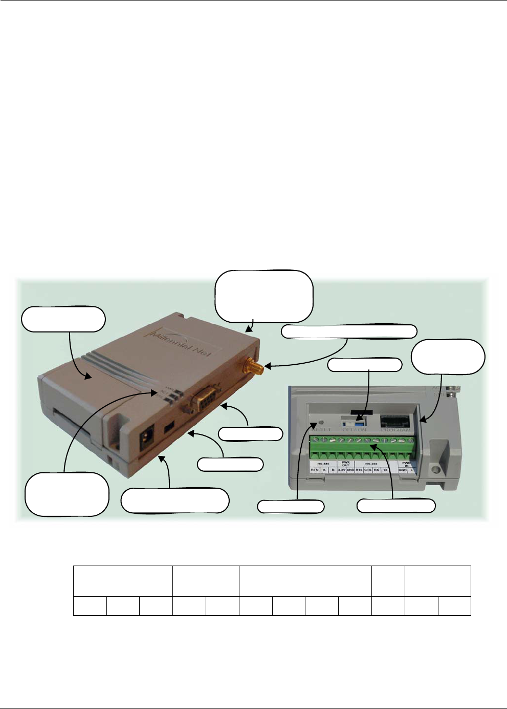
MeshGate Setup (MG-5409)
The MeshGate, model number MG-5409 (label with model number on bottom), is shipped
enclosed in a case that provides access to the antenna, RS-232 data port, console port, and
power connectors as shown in Figure 2-5. Additionally, a lift-off connector panel access cover
on the case provides access to a 12-pin terminal block connector, a reset button, an on/off
switch, and a 6-pin external programming port.
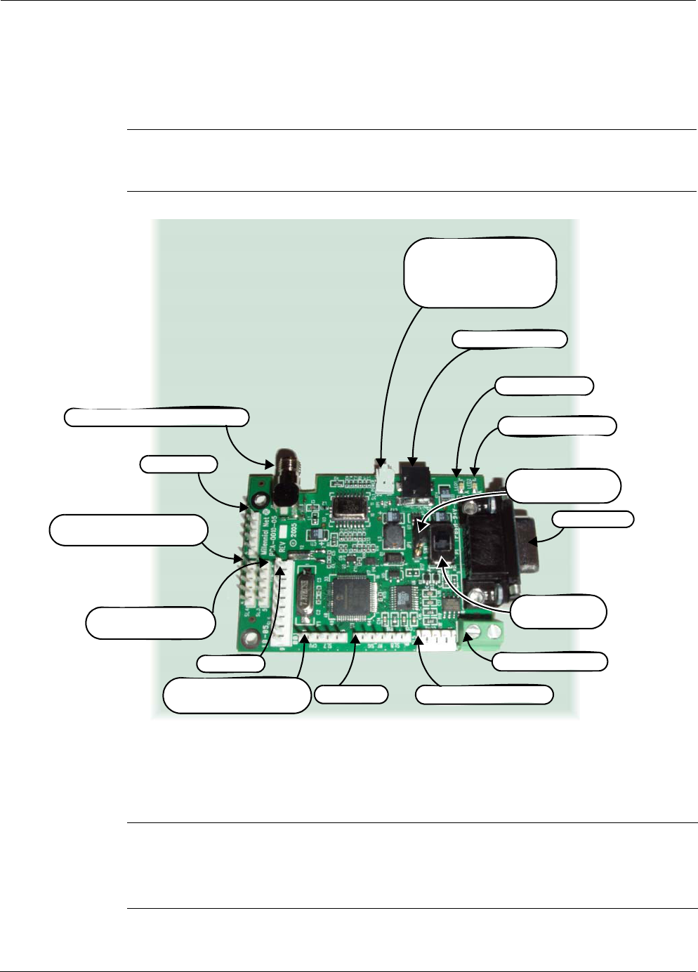
Figure 2-5. MeshGate components
The pin-out for the terminal block is as follows:
During the setup procedure, refer to Figure 2-5 for location of the various MeshGate
components.
RS-485 PWR
OUT
RS-232 PWR
IN
RTN A B 3.3V GND RTS CTS RX TX GND +
REV-SMA Antenna Connector
Power Adapter
Connector
External
Programming
Port
Power LED
RF Activity LED
Status LED
RS-232 Port
Terminal Block
Product Label with:
- Model Number
- GroupID
- Device ID
Console Port
Connector Panel
Access Cover
Reset Button
On/Off Switch

2-4 Millennial Net
Installing the MeshScape System
To set up the MeshGate:
1. Attach one of the four included 1/2-wave antennas to the REV-SMA antenna connector.
The antenna screws onto the connector.
2. Connect the RS-232 cable between the MeshGate and the host PC.
3. Plug the supplied AC adapter into the MeshGate power connector and then into a
110 VAC power source.
4. Remove the connector panel access cover and slide the on/off switch to the ON position.
5. Replace the connector panel access cover.
The MeshGate is ready to interface with the host PC and surrounding network nodes
(mesh nodes and end nodes). For information on the behavior of the status LEDs, see
Table 2-1.
Mounting options
There are three mounting options for the MeshGate:
• desktop
•wall
• DIN rail
Mounting the MeshGate on a Desktop
1. Choose a level, stable surface on which to rest the MeshGate.
2. Install one of the four supplied self-adhesive rubber feet in the round depression located
in each corner on the bottom of the MeshGate chassis.
Mounting the MeshGate on a Wall
1. Place the MeshGate against the wall in the desired mounting location.
2. Mark the location of the two chassis screw holes on the wall.
3. Drill two screw holes in to the wall at the marked locations.
4. Mount the MeshGate to the wall using the two supplied screw anchors and screws.
Caution
When attaching the antenna, only hand-tighten the antenna to the connector.
Using excessive force may damage the connector.
RK-5409-5 Reference Kit User’s Guide 2-5
Installing the Hardware
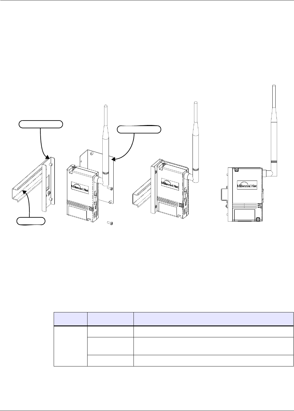
Mounting the MeshGate to a DIN Rail
Millennial Net offers an optional DIN rail mounting kit (MG-DIN) to enable you to mount the
MeshGate to a standard DIN rail easily and quickly.
To mount the MeshGate to a DIN rail using the supplied DIN rail mounting bracket and
hardware, refer to Figure 2-6 and complete the following steps:
Figure 2-6. Mounting the MeshGate to a DIN rail
1. Using two of the supplied screws, secure the MeshGate chassis to the mounting bracket.
2. Mount the adapter bracket onto the DIN rail. Slide the adapter bracket’s clamp up and
then tighten its two screws to secure the adapter bracket in place on the DIN rail.
3. Using two of the supplied screws, secure the mounting bracket to the adapter bracket.
MeshGate status LED operation
Table 2-1 describes how the status LEDs on the MeshGate behave.
Table 2-1. MeshGate status LEDs
LED Led State Status
PWR On Connection with host device detected.
Blinking No host device detected or MeshScape Network Monitor not
running.
Off Power has been removed.
Adapter Bracket
DIN Rail
Mounting Bracket

2-6 Millennial Net
Installing the MeshScape System
MeshGate default settings
Table 2-2 lists the default settings for the MeshGate gateway.
* Persisted indicates value is retained after off/on power cycle.
ACT Flashing Gateway detects RF activity. The Activity LED will flash when
detecting valid packets (packets destined for device) and may also
flash when detecting invalid packets (packets destined for other
devices) or environmental noise. Only valid packets are processed
by the device.
Off No RF activity detected.
STS (Reserved for future use.)
Table 2-2. MeshGate default Settings
Variable
Description Default Value Persisted?*
RS-232 Data Port Configuration RS232
115,200 baud
No parity
No hardware flow control
Yes
Console Port RS232
115,200 baud
No parity
No hardware flow control
Yes
Table 2-1. MeshGate status LEDs
LED Led State Status
RK-5409-5 Reference Kit User’s Guide 2-7
Installing the Hardware
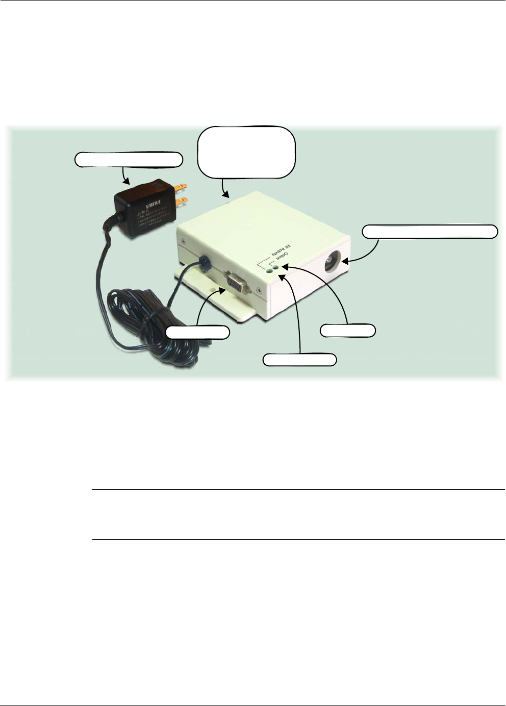
Mesh Node Setup (MN-5409)
The mesh nodes, model number MN-5409 (label with model number on bottom), are shipped
enclosed in cases that have openings for instant access to the antenna, and RS-232 connectors
as shown in Figure 2-7.
Figure 2-7. Mesh node components
Installing antenna and applying power
To install a mesh node:
1. Attach one of the included antennas to the REV-SMA antenna connector. The antenna
screws onto the connector.
2. Connect one of the following power sources supplied with the kit:
–Regulated AC Adapter (recommended): Plug the regulated AC adapter into a 110
VAC power source.
–Batteries: For applications where a 110 VAC power source is not available, the
mesh node can be converted to a battery powered device. For instructions on
installing one of the battery packs contained in the kit, see ’Converting to battery
power’ on page 2-9.
Caution
When attaching the antenna, only hand-tighten the antenna to the connector.
Using excessive force may damage the connector.
REV-SMA Antenna Connector
Regulated AC Adapter
RF Activity LED
RS-232 Port Online LED
Product Label with:
- Model Number
- GroupID
- Device ID

2-8 Millennial Net
Installing the MeshScape System
The mesh node is ready to operate as a router device (see note below). For information
on the behavior of the status LEDs, see Table 2-3.
3. Repeat Steps 1and 2 for each mesh node in the kit.
Mounting options
You may operate the mesh node while it is resting on a desktop or mounted to a wall. When
mounting the mesh node to a wall, we recommend that you secure the mesh node in place
using two #6 screws and screw anchors (not supplied) of the appropriate type for the mounting
surface.
Mesh node status LED operation
Table 2-3 describes how the status LEDs on the mesh node behave.
Mesh node default settings
Table 2-4 lists the default settings for the MeshScape mesh node.
Note:
C
For information on accessing and using the mesh node internal I/O connections for
interfacing with an external device see ’Accessing I/O connections’ on page 2-10.
Table 2-3. Mesh node status LEDs
LED Led State Status
Online On Online and in network.
Blinking Offline and searching.
Off No power.
RF Activity Flashing Mesh node detects RF activity. The RF Activity LED will flash
when detecting valid packets (packets destined for device)
and may also flash when detecting invalid packets (packets
destined for other devices) or environmental noise. Only
valid packets are processed by the device.
Off No RF activity detected.
Table 2-4. MeshScape mesh node default settings
Variable
Description Default Value Persisted?*
Sampling Interval
Defines the time interval between successive
sensor samples sent from end node to MeshGate
300 Seconds No
A/D Converter Setup
Defines state of A/D converter sensor inputs
Channels 0-3 disabled No

RK-5409-5 Reference Kit User’s Guide 2-9
Installing the Hardware
* Persisted indicates value is retained after off/on power cycle.
Converting to battery power
For applications where an AC power source is not available, the mesh node can be converted to
a battery powered device.
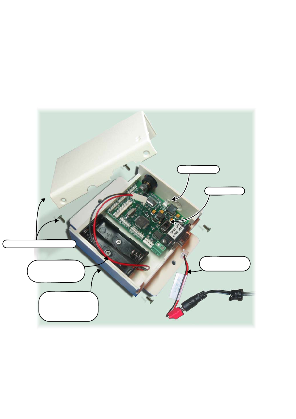
To install an internal battery pack and batteries into an mesh node (see Figure 2-8):
1. Remove the four philips head screws securing the cover to the base, then remove the
cover.
2. Remove the AC adapter connector from SL1 and remove the AC adapter assembly.
3. Turn the Power Switch OFF.
4. Mount one of the battery packs included with the kit to the back cover of the mesh node
using the two mounting screws also included with the kit.
5. Observing polarity, install two AA batteries (not included in kit) into the battery pack.
6. Connect the battery pack to keyed connector SL1.
DIO Setup
Defines state of digital I/O lines
DIO<0:3> configured as
inputs
No
Serial Data configuration
Defines configuration of serial data sensor input,
options are:
Off - DIO<0:3> configured as I/O lines
Digital UART - DIO<0:3> configured as digital
UART signals
RS-232 - 9600 baud, No parity, No hardware flow
control
RS-485 - 9600 baud
Off - DIO<0:3> defined as I/O
lines
No
Label
Text label used to describe sensor
<blank> Yes
(on Network
Monitor host)
Group ID
Network ID used to identify members of the same
wireless network
Pre-programmed
User re-programmable
Yes
Device ID
Device ID used to uniquely identify each node in a
wireless network
Pre-programmed
User re-programmable
Yes
Table 2-4. MeshScape mesh node default settings (continued)
Variable
Description Default Value Persisted?*
2-10 Millennial Net
Installing the MeshScape System
7. Turn the Power Switch ON. The mesh node is ready to operate as a router device (see
note below). For information on the behavior of the status LEDs, see Table 2-3 on page
2-8.
8. Replace the cover and secure in place with the four philips head screws.
Figure 2-8.Installing mesh node battery pack
Accessing I/O connections
Figure 2-9 on page 2-11 provides a mapping of the various I/O connections available on the
mesh node. To run a cable to an I/O connector, a punch-out is provided on the bottom of the
case (to the right of the battery pack shown in Figure 2-8 above).
To access the mesh node’s I/O connectors:
Note:
C
For information on accessing and using the mesh node internal I/O connections for
interfacing with an external device see ’Accessing I/O connections’ on page 2-10.
Cover and Cover Screws (4)
AC Adapter Cable
(remove)
Power Switch
Battery Pack with 2
Mounting Screws
(install)
Connector SL1
Product Label with:
- Model Number
- GroupID
- Device ID
RK-5409-5 Reference Kit User’s Guide 2-11
Installing the Hardware
1. Remove the four cover screws that secure the top cover to the base as shown in Figure
2-8.
2. Lift the top cover off the base.
Figure 2-9. Mesh node components
Note:
C
Configuring and connecting an end node or mesh node to external devices via their
digital or analog I/O connectors is discussed in Chapter 3, “Running MeshScape
Network Monitor”.
Caution
A jumper is factory-installed on JP1 that connects pins 2 and 3 together. Do not
remove or change the position of this jumper as it will cause the device to
malfunction.
REV-SMA Antenna Connector
(SL1) Power Connector
Battery or AC Adapter
Pin 1(right): GND
Pin 2(left): +
Notes: 1. Callouts for SL1–8 and RS-485 point to pin 1 of each connector
2. Connectors labeled as N/A are reserved for future use.
Power Jack (N/A)
Power Switch
ON/OFF
RS-232 Port
LED 1 (Online)
LED 2 (RF Activity)
RS-485 Connector
(SL5) UART Connector
(SL3) DIO
Digital I/O Connector
(SL8) N/A
(SL7) External Firmware
& ID Programming
(SL4) ADC
A/D Converter Connector
(SL2) N/A (JP1) Jumper
Pins 2 & 3 jumped
(SL6) N/A
2-12 Millennial Net
Installing the MeshScape System
End Node Setup (EN-5409)
The end nodes, model number EN-5409, are mounted to terminal boards as shown in Figure
2-10. A terminal board provides easy access to I/O connections and the power switch. The
terminal board also contains a battery holder and battery for supplying power to the end node.
The label on top of the end node contains the device and group IDs assigned to the end node.
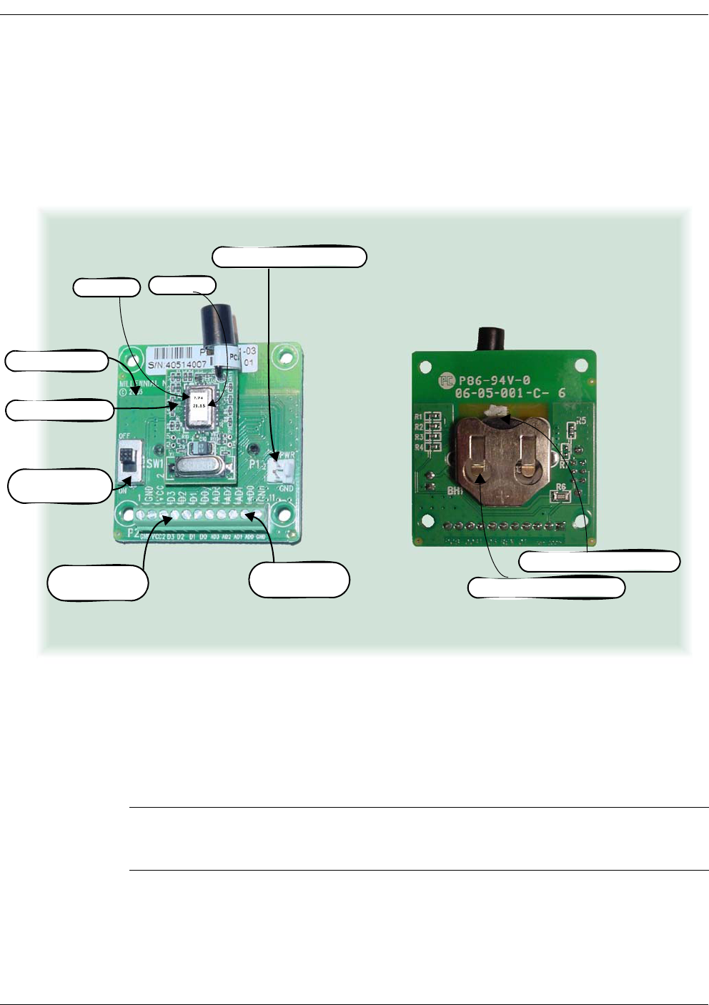
Figure 2-10. End node and terminal board (top and bottom views)
To provide power to the end node, a 3 VDC lithium coin cell (CR2032 type) is provided and
already installed in the battery holder on the back of the terminal board.
To activate an end node:
• Turn the terminal board's power switch ON (refer to Figure 2-10). The end node is ready
to communicate directly or indirectly (through an mesh node) with the MeshGate. Repeat
this step for each end node.
Note:
C
Configuring and connecting an end node or mesh node to external devices via their
digital or analog I/O connectors is discussed in Chapter 3, “Running MeshScape
Network Monitor”.
End Node
Terminal Board
3 VDC Lithium Coin Cell
Lithium Coin Cell Holder
Digital I/O
Ter minals
Power Switch
ON/OFF
Analog I/O
Terminals
Group ID Device ID
(P1) Battery Connector

RK-5409-5 Reference Kit User’s Guide 2-13
Installing the Hardware
Mounting options
A 2-inch x 2-inch plastic housing is supplied with each end node and terminal board. You may
operate the end node installed within its housing while it is resting on a desktop or mounted to
a wall. When mounting the end node housing to a wall, we recommend that you secure it in
place using two #6 screws and screw anchors (not supplied) of the appropriate type for the
mounting surface.
Default settings
Table 2-5 lists the default settings for the MeshScape end node.
* Persisted indicates value is retained after off/on power cycle.
Table 2-5. MeshScape end node default settings
Variable
Description Default Value Persisted?*
Sampling Interval
Defines the time interval between successive
sensor samples sent from End node to MeshGate
10 Seconds No
A/D Converter setup
Defines state of A/D converter sensor inputs
Channels 0-3 disabled No
DIO Setup
Defines state of digital I/O lines
DIO<0:3> configured as
inputs
No
Serial Data configuration
Defines configuration of serial data sensor input,
options are:
Off - DIO<0:3> configured as I/O lines
Digital UART - DIO<0:3> configured as digital
UART signals
Off - DIO<0:3> defined as I/O
lines
No
Label
Text label used to describe sensor
<blank> Yes
(on PC where
Monitor runs)
Group ID
Network ID used to identify members of the same
wireless network
Pre-programmed
User re-programmable
Yes
Device ID
Device ID used to uniquely identify each node in a
wireless network
Pre-programmed
User re-programmable
Yes

2-14 Millennial Net
Installing the MeshScape System
Installing MeshScape Network Monitor
The procedures in this section describe how to do the following:
1. Use the CD-ROM shipped with the reference kit to install the following Millennial Net
items onto the host PC:
– MeshScape Network Monitor
–API software
– EN-5409 End node Tech Sheet
– MG-5409 MeshGate Tech Sheet
– MN-5409 Mesh node Tech Sheet
– RK-5409 MeshScape Users Guide
– RK-5409-5 Kit Contents
– IK-5409 Kit Contents
– Reference Kits Tech Sheet
– 5409 Family Product Sheet
– 5409 MeshScape Release Notes
2. Open a MeshScape Network Monitor session.
The software installation procedure utilizes an InstallShield Wizard that will guide you through
the installation process. When the process is complete, a MeshScape Network Monitor shortcut
icon is also added to the host PC’s desktop.
Installing Contents of Millennial Net’s RK-5409 CD-ROM
To install the software contained on the CD-ROM:
Insert the RK-5409 Reference Kit CD into the host PC’s CD-ROM drive. The Autorun
feature launches the InstallShield Wizard. Follow the prompts to install the contents of
the CD onto the host PC.
If Autorun is not enabled, drill down to the contents of the kit CD and double-click on
setup.exe. The InstallShield Wizard is launched. Follow the prompts to install the
contents of the CD onto the host PC.
Proceed to ’Launching MeshScape Network Monitor Using Windows’ on page 2-15.
Note: If a version of MeshScape Network Monitor already exists on the host PC, it will be
detected during the installation process. A special prompt screen is then displayed,
allowing you to modify, repair, or remove the existing files. You must select
Remove to unistall the exiting version before installing the version contained on the
CD.
RK-5409-5 Reference Kit User’s Guide 2-15
Installing MeshScape Network Monitor
Launching MeshScape Network Monitor Using Windows
Using the standard application launching methods of Windows, the following procedure
describes how to launch MeshScape Network Monitor and verify proper communication with
the network nodes (see Figure 2-11):
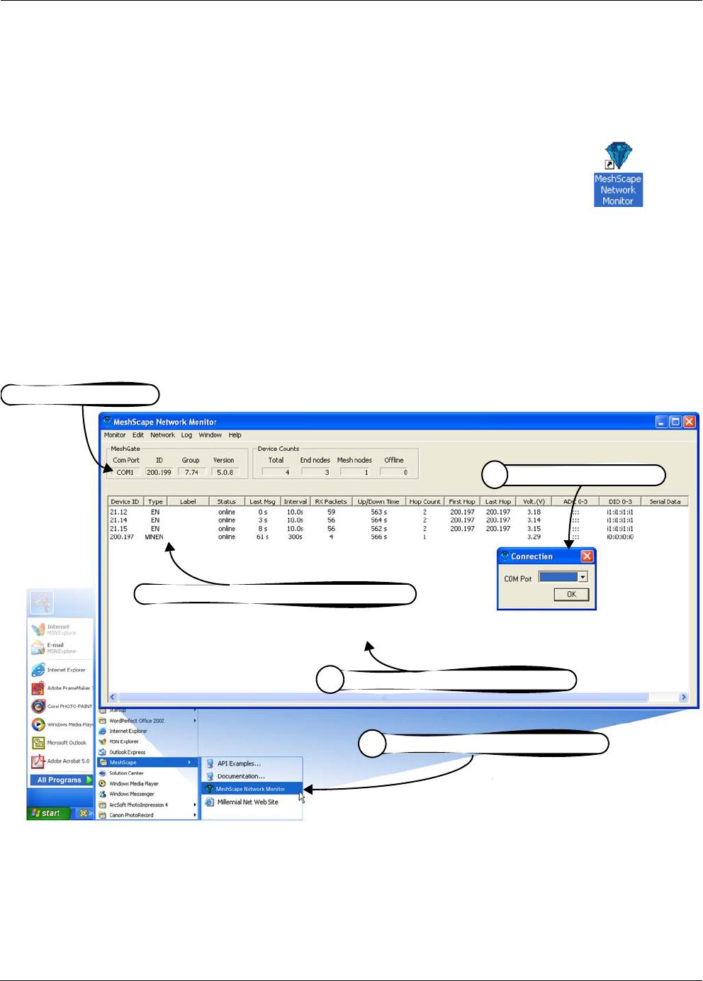
1. To launch MeshScape Network Monitor, do one of the following:
– Double-click on the desktop’s MeshScape Network Monitor icon.
– From the Windows taskbar, select:
Start>All Programs>MeshScape>MeshScape Network Monitor.
2. Enter the COM port on which the host PC is to communicate with the connected
MeshScape.
3. Verify that all network nodes are discovered and displayed by MeshScape Network
Monitor.
Figure 2-11. Using Windows’ Start menu to launch MeshScape Network
Monitor
Once proper operation of the MeshScape System has been verified, proceed to Chapter 3,
“Running MeshScape Network Monitor” for an overview of the GUI and details on how to use
it to configure the operation of your MeshScape System.
Select MeshScape Network Monitor
1
Verify all network nodes are discovered
3
Discovered MeshGate
Discovered end nodes (EN) & mesh nodes (MNEN)
2Specify host PC COM Port

2-16 Millennial Net
Installing the MeshScape System

RK-5409-5 Reference Kit User’s Guide 3-1
3
Running MeshScape Network
Monitor
This chapter provides the following MeshScape Network Monitor information:
•’MeshScape Network Monitor Overview’ on page 3-2
•’Configuring a Node’s Operation’ on page 3-6
•’Labeling an End Node or Mesh Node’ on page 3-19
•’Configuring Persistence Attributes’ on page 3-20
•’Selecting a Com Port on the Host PC’ on page 3-21
•’Configuring Serial and ADC Data Formats’ on page 3-22
•’Turning Event Tracking On/Off’ on page 3-23
•’Broadcasting Data to All Nodes.’ on page 3-24
•’Creating an Event Log File’ on page 3-26
•’Viewing the Contents of an Event Log File’ on page 3-27
3-2 Millennial Net
Running MeshScape Network Monitor
MeshScape Network Monitor Overview
Millennial Net’s MeshScape Network Monitor is a monitoring and management system for
MeshScape networks. This management tool will discover and display active mesh nodes in the
vicinity of the MeshGate, and end nodes in the range of the MeshGate and mesh nodes as
shown in Figure 3-12. MeshScape Network Monitor displays the Group ID and Device ID of the
MeshGate and will display only end nodes and mesh nodes that have the same group ID as the
MeshGate. (For information on opening a MeshScape Network Monitor session, see ’Launching
MeshScape Network Monitor Using Windows’ on page 2-15.)
Using MeshScape Network Monitor, a number of the monitoring features may be observed:
•Any of the mesh nodes can be moved, and as long as they are within the range of
an mesh node or the MeshGate, connectivity will be maintained seamlessly. Any
of the mesh nodes and even the MeshGate can be moved while operating, and all routes
will automatically adapt to their new locations.
•The MeshScape System Persistent Dynamic Routing™ routing protocol always
seeks to route data using the most reliable RF links with the fewest hops. The
network protocol will change the route when an RF link in the route is deemed unreliable.
This can be seen in the MeshScape Network Monitor. For example, the mesh node IDs
used for the first and last hops may change from time to time even when the end node is
stationary, due to environmental interference.
•If any of the mesh nodes runs out of battery power or is turned off, all routes
that went through that mesh node will be reconfigured—all end nodes
communicating with that mesh node will still be connected to other mesh nodes
without any disruption or loss of packets. However, if an end node exceeds the range
of the network due to the loss of an mesh node, then the end node will be displayed as
Offline or removed from the display (depending on how the Persistence function is
configured).
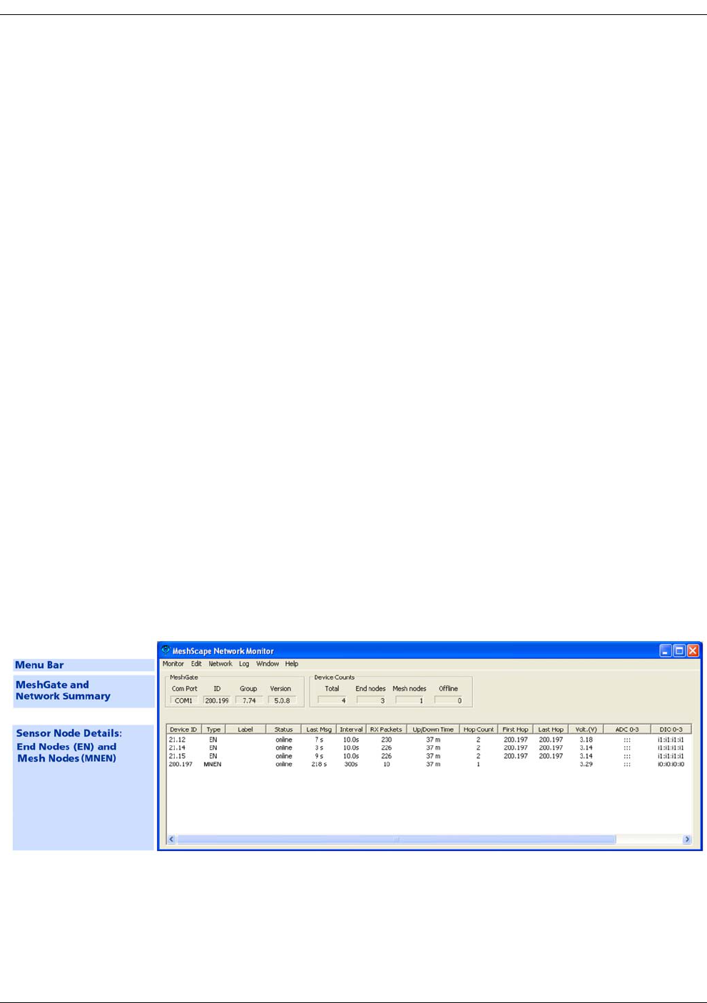
Figure 3-12. Sample MeshScape Network Monitor window

RK-5409-5 Reference Kit User’s Guide 3-3
MeshScape Network Monitor Overview
As shown in Figure 3-12, the main window is divided into the following sections:
Menu Bar
From the menu bar, system users access the following:
• Monitor
This menu option provides access to the following functions:
–Exit: Ends the session and closes MeshScape Network Monitor.
•Edit
– Labels: Assign user-defined names to end nodes and mesh nodes on the network.
For details, see ’Labeling an End Node or Mesh Node’ on page 3-19.
– Persistence: Stop monitoring/displaying offline end nodes and mesh nodes. For
details, see ’Configuring Persistence Attributes’ on page 3-20
–Data Format: Configure the following I/O data formats:
•Serial Data Format: Define format of displayed serial data (ASCII/Hex/Decimal)
•ADC Data Format: Define format of displayed ADC data (Voltage/Raw Data)
For details, see ’Configuring Serial and ADC Data Formats’ on page 3-22.
• Network
–Connection: Select serial port on Host PC to use for MeshGate connection. For
details, see ’Selecting a Com Port on the Host PC’ on page 3-21.
–All Sampling Intervals: Configure all network nodes with the same sampling
interval time. For details, see ’Configuring Sample Interval of all Network Nodes’ on
page 3-8.
–Events: Turn event tracking on or off. Tracked events are included in the Event log
file. For details, see ’Turning Event Tracking On/Off’ on page 3-23.
–Broadcast: Broadcast data to all nodes on your MeshScape system including the
time to which all nodes will synchronize their clocks and Ultra Low Power (ULP)
settings defining wakeup interval and duty cycle for all nodes. For details, see
’Broadcasting Data to All Nodes.’ on page 3-24.
•Log
–Attributes: Create a log file of reported network events, such as reported up/down
events and changes to voltages or routes. For details, see ’Creating an Event Log File’
on page 3-26.
–View: Display contents of log file. For details, see ’Viewing the Contents of an Event
Log File’ on page 3-27.
•Window
–Watch: Display the current status information relating to a node’s interfaces. For
details, see ’Using Watch Function to Display Configuration Information’ on page
3-17.
– Statistics: Open Monitor Statistics window, displaying RX/TX packet and byte
information.
•Help
–About: Displays MeshScape Network Monitor revision level information.

3-4 Millennial Net
Running MeshScape Network Monitor
Gateway
This section displays the following information on the MeshGate connected to the host PC’s
RS-232 port:
•Com Port: Host PC’s RS-232 port connected to MeshGate.
•ID: Device identifier assigned to the MeshGate. The ID consists of two octets (A.B), where
each octet’s value = 000 to 255.
•Group: Group identifier assigned to the MeshGate. All mesh nodes and end nodes with
the same Group identifier will communicate with the displayed MeshGate.
•Version: Version of firmware loaded on the MeshGate.
Device Counts
This section displays the following information on the discovered network nodes:
•Total: Total combined number of discovered end nodes and mesh nodes.
• End nodes: Total number of end nodes currently online.
• Mesh nodes: Total number of discovered mesh nodes currently online.
•Offline: Total number of discovered end nodes and mesh nodes currently offline.
Sensor Node Details
This section displays the following information related to the end nodes and mesh nodes on the
network:
•Device ID: Unique identifier assigned each node. The identifier consists of two octets
(A.B), where each octet contains a value between 000 and 255.
•Type : This column lists all nodes discovered on the network that are assigned the same
group ID as the displayed MeshGate. Nodes displayed here include end nodes (EN) and
mesh nodes (MNEN).
•Label: User-defined name assigned to node.
•Status: Current status of the device:
–Online: The node is communicating with the MeshGate.
–Offline: The MeshGate can no longer communicate with the node.
–Refresh: The node is being updated with a new operating state.
•Last Msg: Time elapsed since last packet was received from the node. Time is displayed in
seconds (s).
•Interval: Time of the last message generated by a node. This value is synchronized with
the sampling interval of the node. Time is displayed in either seconds (s) or minutes (m).

RK-5409-5 Reference Kit User’s Guide 3-5
MeshScape Network Monitor Overview
•RX Packets: Number of packets successfully delivered to MeshScape Network Monitor
from a node since the node was detected by the MeshGate. The counter is reset if one of
the following actions occur:
– The node is powered down.
– The MeshGate is powered down.
– MeshScape Network Monitor program is restarted.
• Up/Down Time: Total time since the node was last detected on/off by the MeshGate.
•Hop Count: Number of network node hops taken by a packet delivered from a node to
the MeshGate. For example: end node—MeshGate = 1 hop,
end node—mesh node—MeshGate = 2 hops (each additional mesh node will add another
hop).
•First Hop: Device ID of the first mesh node on the path used by a packet to get to the
MeshGate. If no mesh node was used, then the field is blank, indicating the device is
communicating directly with the MeshGate.
•Last Hop: Device ID of the last mesh node on the path used by a packet to get to the
MeshGate. If no mesh node was used, then the field is blank, indicating the device is
communicating directly with the MeshGate.
•Volt: DC voltage level of the node’s power source in volts.
•ADC Data: Input voltages on pins used for analog-to-digital conversion operation.
•DIO Data: Digital information on pins used for digital I/O operation.
•Serial Data: Input serial data information when configured for serial operation.
•Version: Version of firmware loaded on the node.
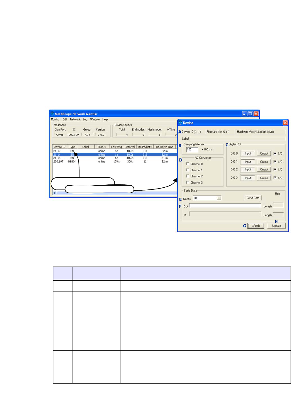
3-6 Millennial Net
Running MeshScape Network Monitor
Configuring a Node’s Operation
To configure the operation of an end node or mesh node, double-click on the desired
device from the list of discovered sensor nodes in the main display. The Device window is
displayed, showing the current configuration of the selected device (see Figure 3-13).
The Device window is a modeless dialog that may be left open while you interact with
other MeshScape Network Monitor features, windows, and dialogs. You can open
multiple instances of the Device window—one per device as needed.
Figure 3-13. MeshScape Network Monitor’s Device window
Table 3-6 describes the functions of the various sections of the window as shown in Figure
3-13.
Table 3-6. Device window functions
Item Description Function
ADevice ID This is the device ID of the node currently selected for configuring.
BSampling Interval This setting configures how often the node transmits a ‘heart beat’ data
packet or any other data.
For details, see ’Configuring Sample Interval of Single Node’ on page
3-8.
CDigital I/O This panel is used to control the states of the I/O pins associated with
digital I/O channels D0–D3.
For details, see ’Configuring Digital I/O Operation’ on page 3-9
DAD Converter This panel is used to control the states of the AD (Analog-to-Digital)
Converter channels.
For details, see ’Configuring AD (analog-to-digital) Converter Operation’
on page 3-14.
Double-click on device . . .
to open Device window

RK-5409-5 Reference Kit User’s Guide 3-7
Configuring a Node’s Operation
ESerial Data
Config
This panel is used to select a serial I/O operation for a device: Digital
UART, RS-232 (MN-5409 only), or RS-485 (MN-5409 only). Selecting
serial operation disables digital I/O functionality because these
operations share the same pins.
For details, see the following:
•’Configuring UART Operation’ on page 3-12
•’Configuring RS-232 Operation (MN-5409 only)’ on page 3-15
•’Configuring RS-485 Operation (MN-5409 only)’ on page 3-16
FSerial Data
Out
This panel, which is only used if the node is configured for serial
operation, is used to send serial data to the node.
For details, see the following:
•’Configuring UART Operation’ on page 3-12
•’Configuring RS-232 Operation (MN-5409 only)’ on page 3-15
•’Configuring RS-485 Operation (MN-5409 only)’ on page 3-16
GWatch This option opens a new widow that displays information relating to the
the node’s various interfaces, including analog and digital I/O
configuration states and packets received/sent.
For details, see ’Using Watch Function to Display Configuration
Information’ on page 3-17
HUpdate Updates the selected device with any changes made to its configuration.
Table 3-6. Device window functions (continued)
Item Description Function
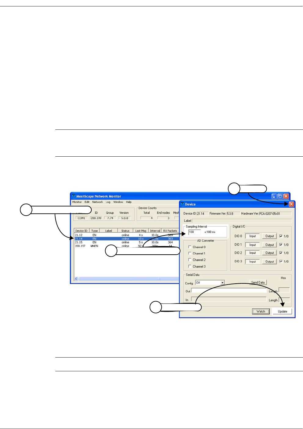
3-8 Millennial Net
Running MeshScape Network Monitor
Configuring Sample Interval of Single Node
To configure the time interval between data packets transmitted by a node (see Figure 3-14):
1. Double-click on the desired device from the list of discovered sensor nodes. The Device
window is opened, displaying the device’s current configuration.
2. Using the Sampling Interval panel, enter the interval sampling rate as a multiple of 100
milliseconds. For example, to configure a sampling interval rate of 10 seconds, enter a
value of 100.
minimum value: 1 (0.1 sec)
maximum value: 65535 (109 minutes)
3. Select Update. The device’s configuration is updated.
4. Select X to exit the Device window.
Figure 3-14. Configuring sample interval of single node
Configuring Sample Interval of all Network Nodes
To configure all the network nodes with the same sampling interval rate (see Figure 3-15):
1. Select Network>All Sampling Intervals. The Edit Sampling Interval window is opened.
Note: After you click Update, the MeshScape Network Monitor will display the ‘Refresh’
state for the device. Changes to the device configuration will show up after one
sampling interval. You can use the Watch window to track configuration changes.
Note: It can take a long time to change the sampling interval for all network nodes.
Double-click on device
1
Configure interval time
2
Select Update
3
Select X
4
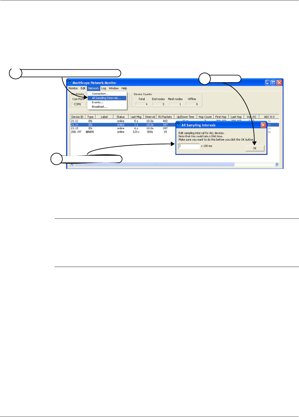
RK-5409-5 Reference Kit User’s Guide 3-9
Configuring a Node’s Operation
2. Enter the interval rate as a multiple of 100 milliseconds. For example, to configure a
sampling interval rate of 20 seconds, enter a value of 200.
3. Select OK. All nodes on the network are configured with the sampling interval rate
entered.
Figure 3-15. Configuring sample interval of all nodes
Configuring Digital I/O Operation
The following procedure describes the steps that need to be taken to set up the hardware and
configure an end node or mesh node for digital I/O operation (see Figure 3-16).
Digital Input Setup
1. Connect the digital source signals to the connectors (D0–D3) and Ground (GND) of:
– end node’s digital terminal block (P2 located on terminal board).
– mesh node’s terminal pins (connector SL3).
See Figure 3-16 on page 3-11 for connector locations.
2. From MeshScape Network Monitor, double-click on the desired device from the list of
discovered sensor nodes. The Device window is opened, displaying the device’s current
configuration.
3. From the Digital I/O panel, select Input on each of the desired digital channels to use as
inputs (DIO 0—DIO 3), then select Update.
MeshScape Network Monitor displays the digital information for the node in the Digital
I/O Data column, where On = output channel and In = input channel (n = 1 or 0).
Note: (End nodes only) The end node terminal board contains pullup resistors connecting
its digital I/O pins to Vcc to prevent them from floating. If the I/O pins float, the
current consumption of the end node could increase substantially and affect battery
life. When using the end nodes with other hardware designs, be sure that all the
unused digital I/O inputs are pulled up to Vcc and not left floating. Also, be sure that
the inputs being used are compatible with the end node’s digital I/O.
Select Network>All Sampling Intervals
1
Configure interval time
2
Select OK
3

3-10 Millennial Net
Running MeshScape Network Monitor
Digital Output Setup
1. Connect the digital signal destination devices to the connectors (D0–D3) and ground
(GND) of the following:
– end node’s terminal block (P2 located on terminal board).
– mesh node’s terminal pins (connector SL3).
See Figure 3-16 on page 3-11 for connector locations.
2. From MeshScape Network Monitor, double-click on the desired device from the list of
discovered sensor nodes. The Device window is opened, displaying the device’s current
configuration.
3. From the Digital I/O panel, select Output on each of the desired digital channels to use
as outputs (DIO 0—DIO 3).
4. Set the output signal high or low using the 1/0 box located next to the desired Output
button:
– Selected = 1 (output is set high)
– Not selected = 0 (output is set low)
5. Select Update.
MeshScape Network Monitor displays the digital information for the node in the Digital
I/O Data column, where On = output channel and In = input channel (n = 1 or 0).
Note: Input signals should not be applied when the end node is switched off. Since the
node is an extremely low power device, it’s possible that the input signal voltages
will keep the microcontroller active, preventing it from resetting properly when
switched back on. Also, when switched off, the terminal board will ground certain
pins, which can cause excessive current drain for the external peripheral connected
to it.
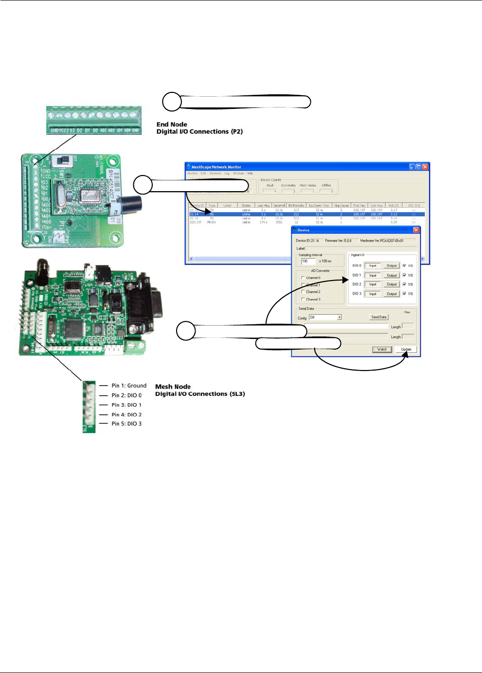
RK-5409-5 Reference Kit User’s Guide 3-11
Configuring a Node’s Operation
Figure 3-16. Configuring end node or mesh node for digital I/O
Connect external digital device
1
Configure digital channels,
3
then select Update
Double-click on device
2

3-12 Millennial Net
Running MeshScape Network Monitor
Configuring UART Operation
The following procedures describes how to use the end node’s digital I/O connections or the
mesh node’s UART connector for serial/UART communications (see Figure 3-17). Refer to the
technical specification sheets for the end node and mesh node for additional information
required when using the device for serial communications.
1. Connect to the following:
– end node’s P2 terminal block (pins D0–D3, GND).
– mesh node’s SL5 connector.
2. From MeshScape Network Monitor, double-click on the desired device from the list of
discovered sensor nodes. The Device window is opened, displaying the device’s current
configuration.
3. From the Config panel, select Serial Data: Digital UART, then Update. The UART
terminal block is ready for UART operation (digital function is disabled).
4. (optional) To send serial data to the node, enter the data in the Out panel, then select
Send Data.
Note: The end node supports the following serial communication parameters:
9600 bps, 8 data bits, no parity, 1 stop bits
The mesh node supports the following serial communication parameters:
9600 bps, 8 data bits, no parity, 2 stop bits
Serial data and digital I/O are mutually exclusive operations for end nodes.
Caution
When making serial connections to an end node,
use an adapter to scale the RS-232 voltages to 3 volt digital logic.
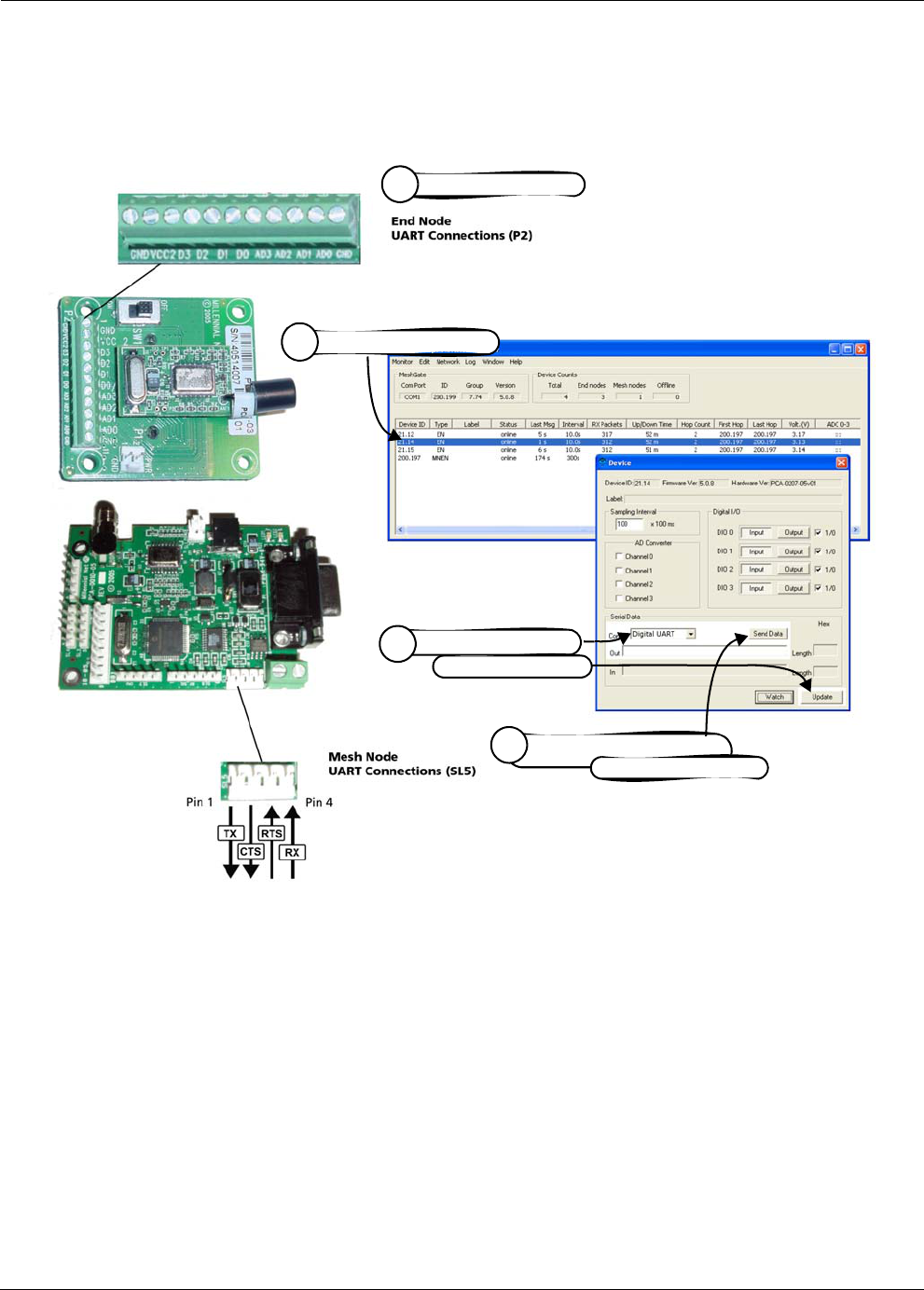
RK-5409-5 Reference Kit User’s Guide 3-13
Configuring a Node’s Operation
Figure 3-17. Configuring end node or mesh node for UART operation
Connect serial I/O’s
1
(optional) Enter serial data,
4
then select Send Data
Select Digital UART,
3
then select Update
Double-click on device
2
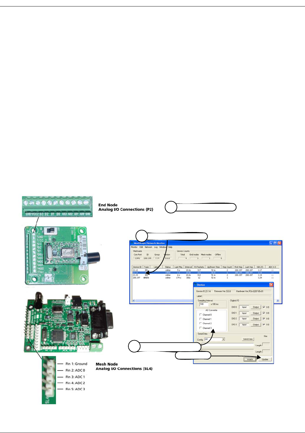
3-14 Millennial Net
Running MeshScape Network Monitor
Configuring AD (analog-to-digital) Converter Operation
The following procedure describes the steps that need to be taken to set up the hardware and
configure an end node or mesh node for AD Converter operation (see Figure 3-18):
1. Connect 0–3 VDC signals to the following A/D Converter connectors:
– end node: Connect signal source ground to GND_CPU of the A/D Converter terminal
block.
– mesh node: Connect signal source ground to Pin 1 (Ground) of connector SL4.
Use any or all of the A/D Converter channels (AD0–AD3/Pins 2–5) for connecting analog
signal sources.
2. From MeshScape Network Monitor, double-click on the desired device from the list of
discovered sensor nodes. The Device window is opened, displaying the device’s current
configuration.
3. From the AD Converter panel, select the AD Converter channels to which the external
analog signals have been connected, then select Update.
MeshScape Network Monitor displays the analog information for the node in the ADC
(V) column.
Figure 3-18. Configuring end node/mesh node for analog I/O
Connect 0–3 V signals
1
Select analog channels,
3
then Update
Double-click on device
2
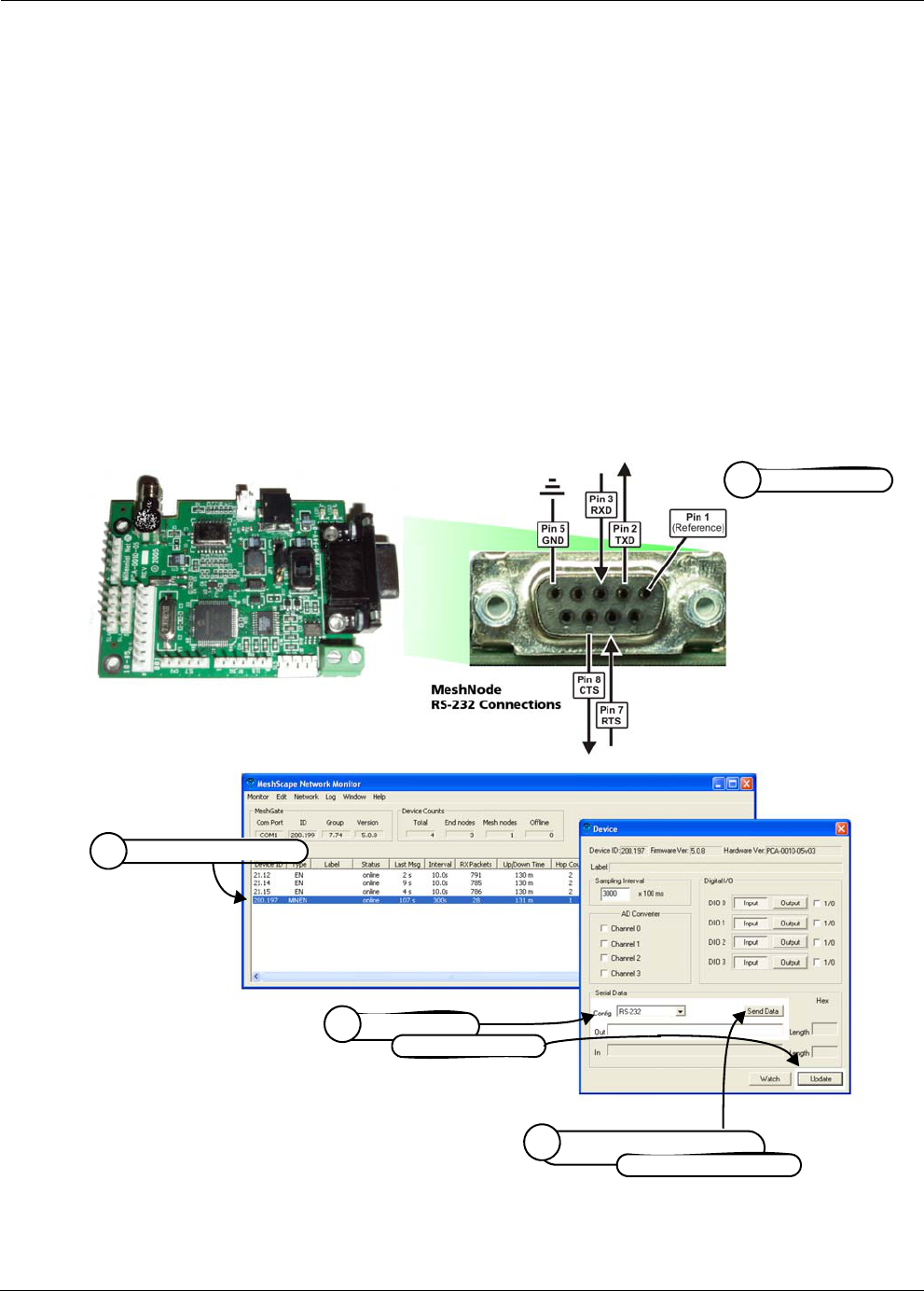
RK-5409-5 Reference Kit User’s Guide 3-15
Configuring a Node’s Operation
Configuring RS-232 Operation (MN-5409 only)
The following procedure describes the steps that need to be taken to set up the hardware and
configure a mesh node for RS-232 operation (see Figure 3-19):
1. Use a DB-9 cable to connect the network device to the RS-232 female connector using
the pinout information provided in Figure 3-19.
2. From MeshScape Network Monitor, double-click on the desired device from the list of
discovered sensor nodes. The Device window is opened, displaying the device’s current
configuration.
3. From the Config panel, select Serial Data: RS-232, then Update. The RS-232 connector is
ready for operation (digital function is disabled).
4. (optional) To send serial data to the mesh node, enter the data in the Out panel, then
select Send Data.
Figure 3-19. Configuring mesh node for RS-232
Connect signals
1
(optional) Enter serial data,
4
then select Send Data
Select RS-232,
3then select Update
Double-click on device
2
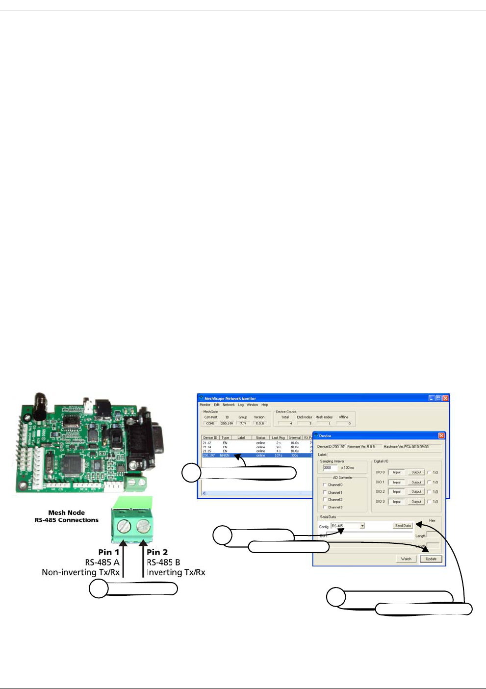
3-16 Millennial Net
Running MeshScape Network Monitor
Configuring RS-485 Operation (MN-5409 only)
The RS-485 interface of the mesh node operates using the following parameters:
• Half-duplex mode
• 9600 baud
• Transmitting data: Maximum byte length for one request is 80 bytes
• Receiving data: Reception is terminated by the mesh node when the maximum input byte
length is reached or there is no input for more than 20 ms. Once the input is terminated,
the data is transferred to MeshScape Network Monitor.
The following procedure describes the steps that need to be taken to set up the hardware and
configure a mesh node for RS-485 operation (see Figure 3-20):
1. Connect the network device to the standard 2-position RS-485 terminal block using the
pinout information provided in Figure 3-20. The terminal block will accept 26 AWG to 16
AWG wire.
2. From MeshScape Network Monitor, double-click on the desired device from the list of
discovered sensor nodes. The Device window is opened, displaying the device’s current
configuration.
3. From the Digital I/O panel, select Serial Data: RS-485, then Update. The RS-485
connector is ready for operation (digital function is disabled).
4. (optional) To send serial data to the mesh node, enter the data in the Serial Data panel,
then select Send Data.
Figure 3-20. Configuring mesh node for RS-485
Connect signals
1(optional) Enter serial data,
4
then select Send Data
Select RS-485,
3then select Update
Double-click on device
2
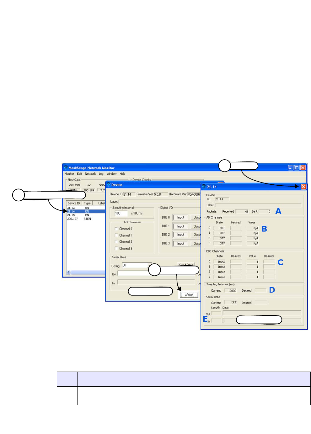
RK-5409-5 Reference Kit User’s Guide 3-17
Configuring a Node’s Operation
Using Watch Function to Display Configuration Information
Use the Watch window to track changes to a device’s configuration.
You may open multiple instances of the Watch window. The selected device’s ID and label (if
configured) are displayed in the Watch window title bar.
To display the current and desired configuration for a device (see Figure 3-21):
1. Double-click on the desired device from the list of discovered sensor nodes. The Device
window is opened, displaying the device’s current configuration.
2. Select Watch. The Watch window is opened, displaying the selected device’s current and
desired configuration information.
3. Select X to exit the Watch window.
Alternatively, click once on a device and then select Window>Watch to open the Watch
window for that device.
Figure 3-21. Displaying I/O information using Watch function
Table 3-7 describes the functions of the various sections of the Watch window as shown in
Figure 3-21.
Table 3-7. Watch window functions
Item Description Function
APackets
Received/Sent
Total packets received from or transmitted to the node.
Watch window
Select Watch
2
Device window
Double-click on device
1
Select X
3

3-18 Millennial Net
Running MeshScape Network Monitor
BA-D Channels This panel displays the following information for each analog-to-digital
channel (0–3):
•State: Current on/off state of the channel
•Desired: Desired on/off state of channel, which can be changed
using the Device window.
•Value: Numeric values of the channel.
CDIO Channels This panel displays the following information for each digital channel
(0–3):
•State: Current input/output state of the channel
•Desired: Desired input/output state of channel, which can be
changed using the Device window.
•Value: I/O values of the channel (1 or 0).
•Desired: Desired I/O value of channel.
DSampling Interval This panel displays the following sampling interval information:
•Current: Currently configured setting.
•Desired: Desired setting, which can be changed using the Device
window (see ’Configuring Sample Interval of Single Node’ on page
3-8).
ESerial Data This panel displays the following serial data information of data received
from the node (In) or transmitted to the node (Out):
•Current: Currently configured setting (Off, RS-232, RS-485)
•Desired: Desired setting
•Length: Length of string received/transmitted.
Table 3-7. Watch window functions (continued)
Item Description Function
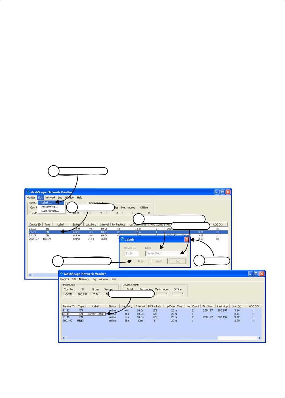
RK-5409-5 Reference Kit User’s Guide 3-19
Labeling an End Node or Mesh Node
Labeling an End Node or Mesh Node
Labels are meaningful, persistent text strings used to identify network nodes beyond their
group and device IDs.
The following procedure describes the steps required to assign a label to an end node or mesh
node (see Figure 3-22):
1. From MeshScape Network Monitor, click on the desired device from the list of discovered
sensor nodes.
2. From MeshScape Network Monitor, select Edit>Labels. The Edit Labels window is
opened.
3. Enter the label to be applied to the node, then select Set. MeshScape Network Monitor
displays the label in the Label column of the selected node.
4. Click Prev or Next to apply labels to other discovered sensor nodes.
5. Select X to exit the Edit Label window.
Figure 3-22. Labeling an end node or mesh node
Enter label information,
3
then select Set
Select X
5
Click Device
1
Node label added
Select Prev or Next
4
Select Edit>Labels
2
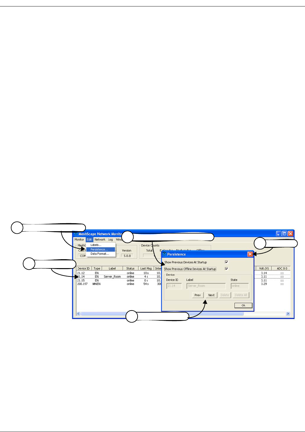
3-20 Millennial Net
Running MeshScape Network Monitor
Configuring Persistence Attributes
The following procedure describes how to configure the persistence setting of the network’s
end nodes and mesh nodes (see Figure 3-23):
1. From MeshScape Network Monitor, click on the desired device from the list of discovered
sensor nodes.
2. From MeshScape Network Monitor, select Edit>Persistence. The Edit Persistence
window is opened.
3. Configure the following persistence attributes:
–Show previous devices at startup: If selected, all online nodes will be displayed
when MeshScape Network Monitor is started.
–Show previous offline devices at startup: If selected, all online and offline nodes
will be displayed when MeshScape Network Monitor is started.
–Delete: Select the delete button to stop displaying the selected Offline node.
–Delete all: Select this delete button to stop displaying any node with a status of
Offline.
4. Click Prev or Next to apply persistence attributes to other discovered sensor nodes.
5. Select X to exit the Edit Persistence window.
Figure 3-23. Configuring node persistence attributes
Select Edit>Persistence
2
Select X
5
Configure persistence attributes
3
Click Device
1
Select Prev or Next
4
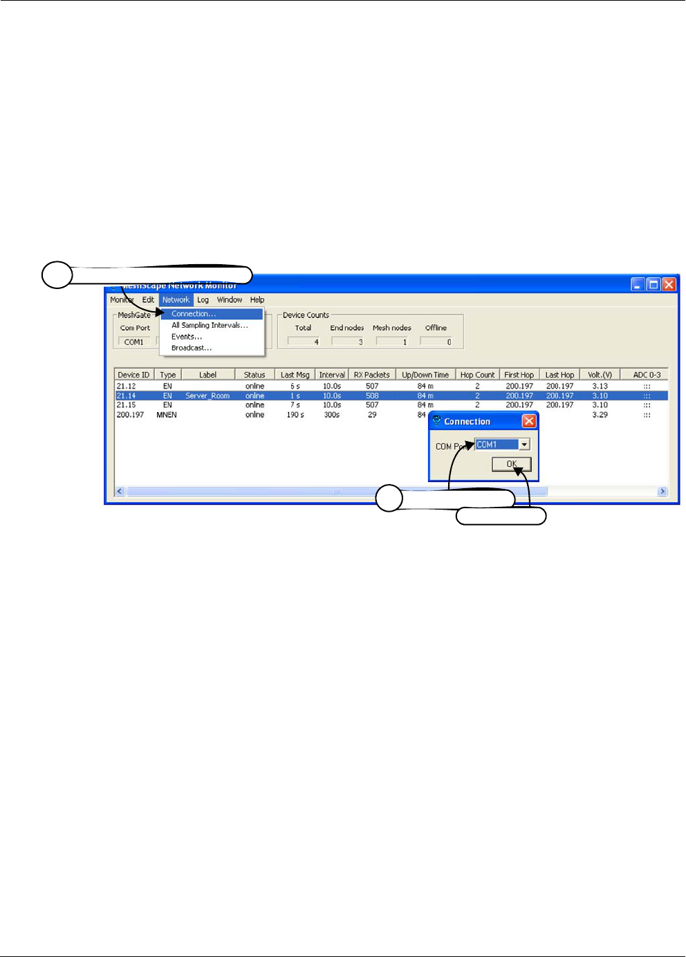
RK-5409-5 Reference Kit User’s Guide 3-21
Selecting a Com Port on the Host PC
Selecting a Com Port on the Host PC
The following procedure describes how to select the RS-232 com port for MeshScape Network
Monitor to use to communicate with the MeshGate (see Figure 3-24):
1. From MeshScape Network Monitor, select Network>Connection. The Connection
window is opened.
2. Select the RS-232 com port to use from the drop down list of available ports, then select
OK. MeshScape Network Monitor communicates with the MeshGate connected to the
selected port.
Figure 3-24. Selecting com port on host PC
Select Network>Connection
1
Select port to use,
2
then select OK
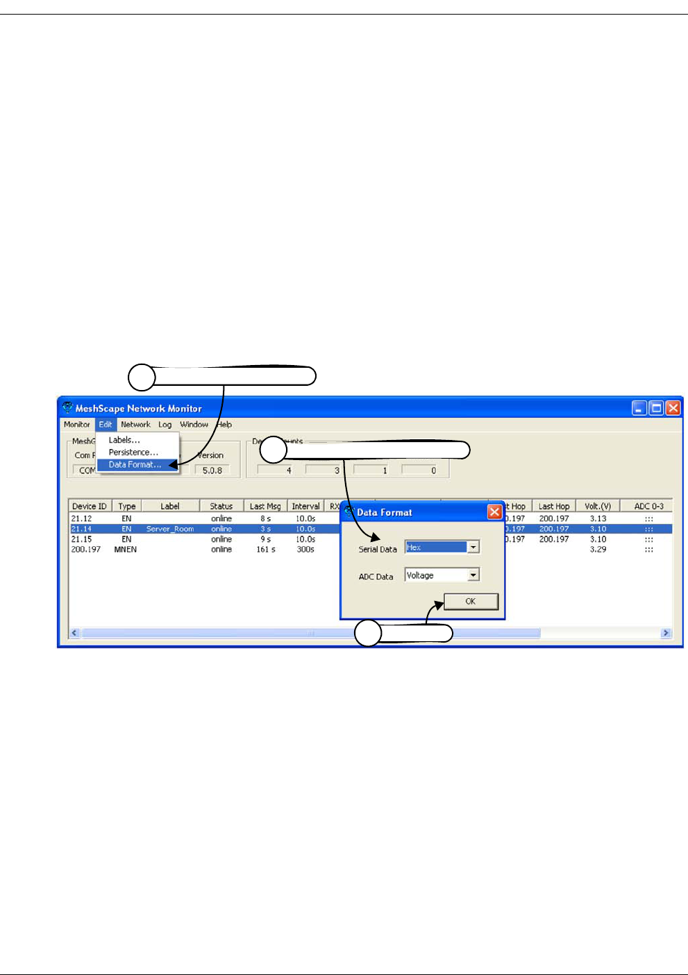
3-22 Millennial Net
Running MeshScape Network Monitor
Configuring Serial and ADC Data Formats
The following procedure describes how to configure the format of displayed serial and ADC
information (see Figure 3-25):
1. From MeshScape Network Monitor, select Edit>Data format. The Edit Data Format
window is opened.
2. Configure the following network attributes:
–Serial data format: Select the desired format for displaying serial data
(ASCII/Hex/Decimal).
–ADC data format: Select the desired format for displaying ADC data
(Voltage/Raw Data).
3. Select OK to save the settings and exit the Edit Network window.
Figure 3-25. Configuring serial and ADC data formats
Select Edit>Data Format
1
Select OK
3
Configure data format attributes
2
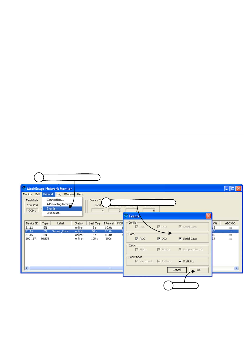
RK-5409-5 Reference Kit User’s Guide 3-23
Turning Event Tracking On/Off
Turning Event Tracking On/Off
The following procedure describes how to turn event tracking on or off. Tracked events are
recorded in the Event log file (see Figure 3-26):
1. From MeshScape Network Monitor, select Network>Events. The Events window is
opened.
2. Configure the following event tracking settings:
–Configuration Events: Display event tracking status for Analog-to-digital
Converter, Digital Input/Output, and Serial configuration events.
–Data Events: Turn event tracking on/off for Analog-to-digital Converter, Digital
Input/Output, and Serial data events.
–Static Events: Display event tracking status for device State, Status, and Sampling
Interval events.
–Heartbeat: Display event tracking status for device Heartbeat and Battery Level
events. Display event tracking status for Statistical events.
3. Select OK to save the settings and exit the Events window.
Figure 3-26. Turning device event tracking on/off
Note: Events for which tracking cannot be turned off appear grayed out in the Events
window.
Select Network>Events
1
Select OK
3
Turn on/off event tracking
2

3-24 Millennial Net
Running MeshScape Network Monitor
Broadcasting Data to All Nodes.
You can broadcast the following data to all nodes on your MeshScape System:
• The time to which all nodes will synchronize their clocks
• Ultra Low Power (ULP) settings defining wakeup interval and duty cycle for all nodes
The following procedure describes how to broadcast data to all nodes (see Figure 3-26):
1. From MeshScape Network Monitor, select Network>Broadcast. The Broadcast window
is opened.
2. Configure the following broadcast settings:
–Synchronize device clock: Set the time with which the node clocks are to
synchronize. Mark the Use host clock check box to broadcast the time set on the
host PC on which the MeshScape Network Monitor is running, or alternatively, enter
the date and time to broadcast.
–Wakeup interval: The wakeup interval determines the Mesh Node wakeup cycle.
Minimum value for the wakeup interval is 60000 milliseconds, and the maximum
value is 6540000 milliseconds.
–Duty ratio: The duty ratio determines how long the Mesh Node stays awake and
how long it sleeps during each wakeup interval. The duty ratio is defined as
100*(awake time)/(wakeup interval). Note that the wakeup interval = awake time +
sleep time. The duty ratio has no unit.
The units for specifying the duty cycle is tenths of a percent. The recommended
Minimum value for the duty ratio is 5 (represent 0.5%), and the Maximum value is
1000 (represents 100.0%) set in increments of 5.
3. Select Validate to verify your ULP settings are valid and within range.
4. Select OK to save the settings and exit the Broadcast window.
Note: Broadcasting capabilities are available on your MeshScape only if you have enabled
(i.e., unlocked) the ultra-low power feature.
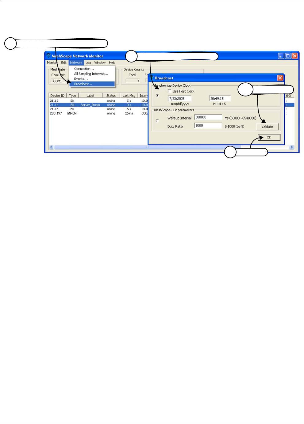
RK-5409-5 Reference Kit User’s Guide 3-25
Broadcasting Data to All Nodes.
Figure 3-27. Broadcasting data to all nodes
Select Network>Broadcast
1
Select OK
4
Define broadcast settings
2
Select Validate
3
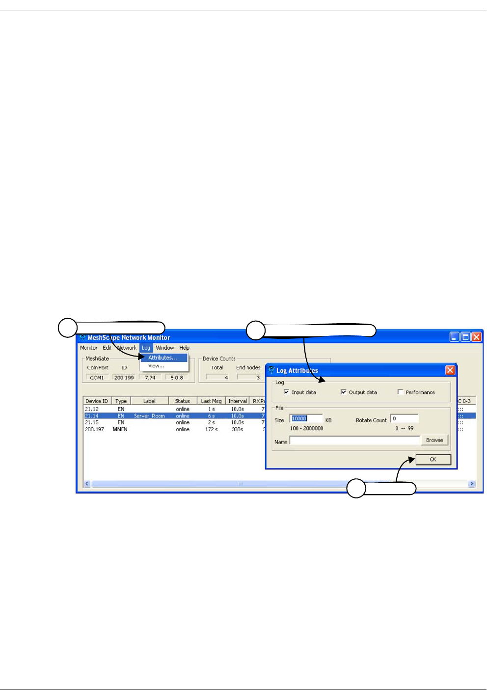
3-26 Millennial Net
Running MeshScape Network Monitor
Creating an Event Log File
The following procedure describes the steps required to have MeshScape Network Monitor
record reported network events to a log file (see Figure 3-28):
1. From MeshScape Network Monitor, select Log>Attributes. The Edit Logging Attributes
window is opened.
2. Configure the following mesh node and end node log file attributes:
–Log data: Record input/output/performance data.
–File size n KB: Clear the log file and begin the recording process again when it
reaches the designated file size and rotate count number.
–Rotate Count n: Number of history log files to maintain. Once this value is reached,
files are written over.
–Name: Assign a name to the log file and define where the file is saved.
3. Select OK to activate the logging process.
To view the contents of the log file, see ’Viewing the Contents of an Event Log File’ on page
3-27.
Figure 3-28. Configure an event log file
Select OK
3
Configure log file attributes
2
Select Log>Attributes
1
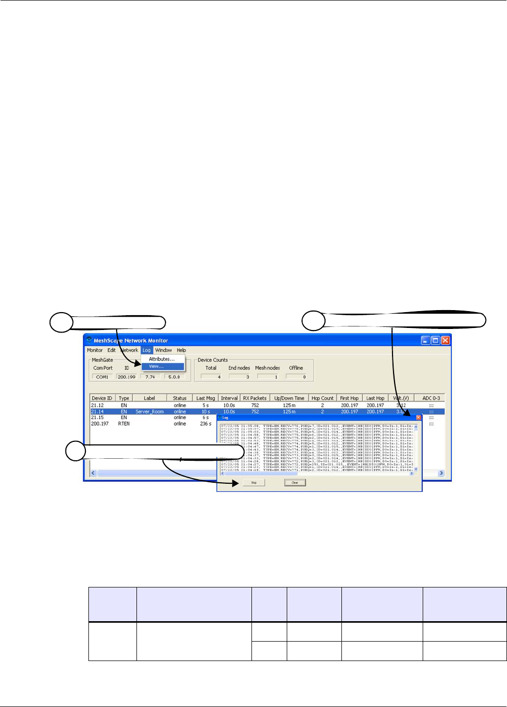
RK-5409-5 Reference Kit User’s Guide 3-27
Viewing the Contents of an Event Log File
Viewing the Contents of an Event Log File
The following procedure describes how to view the network event log file generated by
MeshScape Network Monitor, which records node-generated events (see Figure 3-29):
1. From MeshScape Network Monitor, select Log>View. The log file window is opened,
displaying the user-defined event log information (see also ’Creating an Event Log File’ on
page 3-26).
2. Select one of the following:
–Stop/Restart: Select this toggle option to stop and restart a recording session.
–Clear: Select this option to clear the information currently displayed and start a new
recording session.
You can copy and paste event log data to the Windows clipboard.
To configure the events to track and include in the log file, see ’Turning Event Tracking On/Off’
on page 3-23.
To configure the attributes of the log file that get recorded and displayed, see ’Creating an
Event Log File’ on page 3-26.
Figure 3-29. View contents of event log file
Table 3-8 describes the event keys (see example) displayed in the log file.
example: 04/22 11:00:42, Type=EN, RCV=100, PSEQ=28, ID=021.015,
Event=|HB|DIO|PFM, D0=In:1, D1=In:1, D2=In:1, D3=In:1
Table 3-8. Event log key definitions
Key Key Meaning
Sub-
Key
Sub-Key
Meaning
Output to
device example
Input to device
example
A0 ... A3 ADC Channel 0 ... 3 En Enabled A0=En A0=2.12
Dis Disabled A1=Dis
Select Log>View
1
Select Stop/Restart or Clear
2
Click X to close the log file display
3

3-28 Millennial Net
Running MeshScape Network Monitor
D0 ... D3 Digital I/O Channel 0 ... 3 In Input D0=In D0=In:1
Out Output D1=Out:1
EP Endpoint N/A N/A EP=001.001 EP=001.002
FH First Hop Mesh Node N/A N/A N/A FH=001.002
HC Hop Count N/A N/A N/A HC=3
LH Last Hop Mesh Node N/A N/A N/A LH=002.003
RCV Receive N/A N/A N/A RCV=200
(sequence
number)
MNEN Mesh Node N/A N/A RT=200.001 RT=200.001
SER Serial Interface N/A N/A SER=12 34 56 13 SER=12 34 56 13
SI Sampling Interval N/A N/A SI=100.0 SI=200.0
SND Send N/A N/A SND=100
(sequence
number)
N/A
ST State On Online ST=On
Off Offline
Ref Refreshing
Table 3-8. Event log key definitions (continued)
Key Key Meaning
Sub-
Key
Sub-Key
Meaning
Output to
device example
Input to device
example

RK-5409-5 Reference Kit User’s Guide 3-29
Viewing MeshScape Statistics
Viewing MeshScape Statistics
The following procedure describes how to view the network statistics recorded by MeshScape
Network Monitor, which provides information on the packets received and transmitted by the
network nodes (see Figure 3-30):
1. From MeshScape Network Monitor, select Window>Statistics. The Statistics window is
opened, displaying the following information:
– Sample Time: Current date and time.
–Start Time: Date/time statistics recording session began.
–Elapsed Time: Total recording time.
–Count Down: Seconds before next sample is taken and window is refreshed.
–RX Bytes: Total bytes received.
–RX Packets: Total packets received.
–End Node Packets: Packets received from end nodes.
–Mesh Node Packets: Packets received from mesh nodes.
–MeshGate Packets: Packets received from MeshGate.
–Notify Packets: Packets sent from MeshGate to MeshScape Network Monitor for
notification events.
–TX Bytes: Total bytes transmitted.
–TX Packets: Total packets transmitted.
2. (optional) Select Reset to clear the information currently displayed and begin a new
recording session.
Caution
Selecting Reset will remove all statistics collection history.
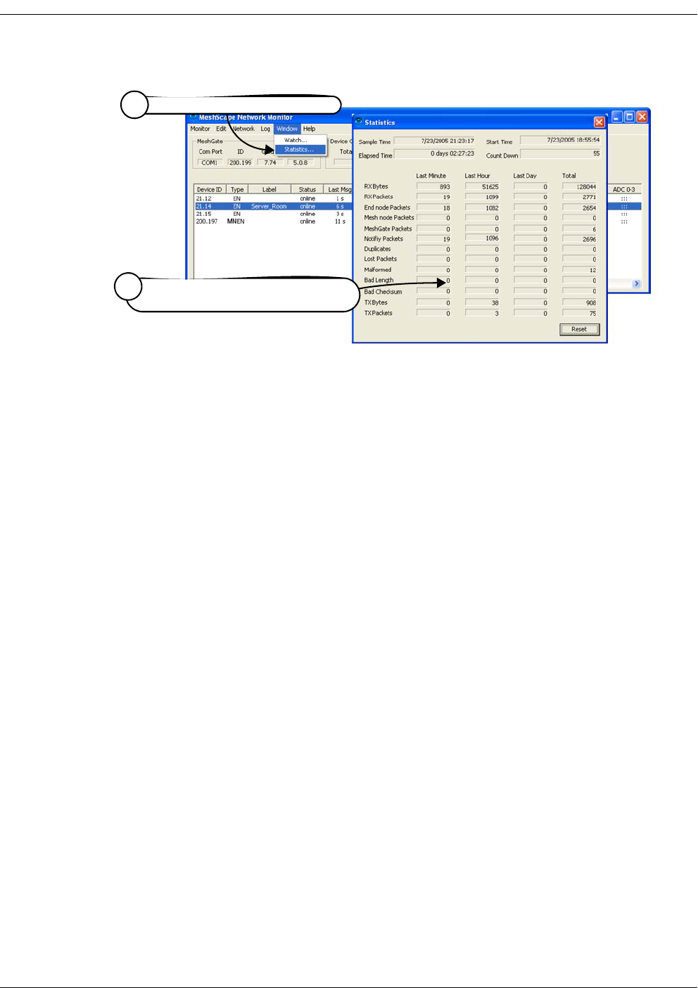
3-30 Millennial Net
Running MeshScape Network Monitor
Figure 3-30. Viewing MeshScape statistics
Select Window>Statistics
1
(optional) Select Reset to clear display
and start new recording session
2

RK-5409-5 Reference Kit User’s Guide 4-1
4
Using the MeshScape API
This chapter describes the following API functions:
•’Using the MeshScape API’ on page 4-2
•’MeshScape API Functions Overview’ on page 4-5
•’iBeanAPI.h’ on page 4-7
•’iBeanAPI_IO.h’ on page 4-23
•’iBeanAPI_Utils.h’ on page 4-32
•’iBeanAPI_LPR.h’ on page 4-36
•’iBeanAPI_performance.h’ on page 4-39
•’Example API Code’ on page 4-42
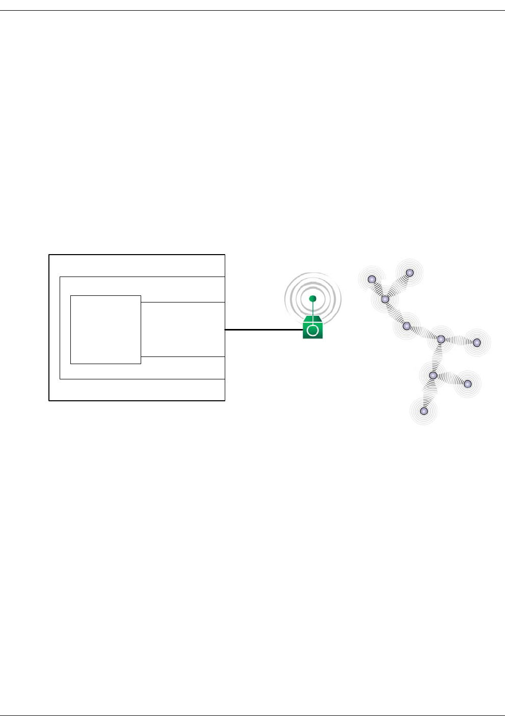
4-2 Millennial Net
Using the MeshScape API
Using the MeshScape API
Millennial Net’s MeshScape™ API enables you to effectively use the features provided by
Millennial Net’s MeshScape wireless sensor network. You can develop custom applications that
utilize the MeshScape API library on Windows- or Linux-based platforms such as Network
Controllers, PCs, or PDAs.
The Millennial API provides a serial command set that enables a MeshScape MeshGate
standalone gateway to communicate with user applications via a serial interface. The serial
interface transports a byte stream-based protocol that provides MeshScape API equivalent
functionality. The commands operate in both a query/response and an autonomous event
notification manner.
Figure 4-1. Using the MeshScape API
Network Controller
Serial
Interface
Application MeshScape API
Linux/Windows OS
MeshGate
Gateway
MeshScape
Wireless Sensor Network
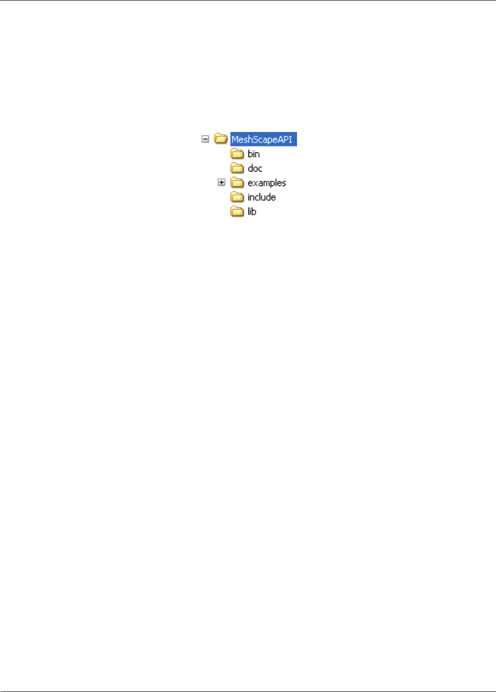
RK-5409-5 Reference Kit User’s Guide 4-3
MeshScape API Directory Structure
MeshScape API Directory Structure
The MeshScape API sub-directory contains five sub-directories which hold the API related files,
including header files, dll and library files, and various compiled examples along with their
source code listings. Figure 4-2 is a representation of the directory structure.
Figure 4-2. MeshScape API directories
The contents of each directory is described below.
bin Directory:
This sub-directory contains the iBeanAPI.dll file required for running API related
applications. This dll file is compiled with Microsoft’s Visual Studio .Net edition and
therefore only supports Microsoft Visual C++ programming conventions.
doc Directory:
This sub-directory contains the MeshScape system user documentation in Adobe Acrobat
(.pdf) format including:
–RK-5409-5 Reference Kit User’s Guide (i.e., this guide)
– RK-5409-5 916 MHz MeshScape™ Reference Kit Contents & Getting Started Guide
– MeshScape Product Family Sheet
– Technical specifications for MeshGate gateway, mesh node, and end node
– Release notes
examples Directory:
This sub-directory contains the iMDLL5k.dll file along with pre-compiled API executables.
These executables are compiled with Microsoft’s Visual Studio .Net edition and are
designed to run under Windows XP and Windows 2000. The source code along with
sample Microsoft Visual Studio .Net solution file for these example applications can be
found in the /src sub-directory. Here is a brief description of the API example applications:
– ListDevicesVC7.exe: This is a console based application that lists current online
devices. For a detailed look at this example and its code, see ’Example API Code’ on
page 4-42.
– ReadSerialVC7.exe: This is a console based application that reads serial data received
from any online device on the network that has serial interface enabled.
– SetSamplingVC7.exe: This is a console based application that changes the sampling
interval of the online devices.
– TempMonitor.exe: This is a console based application that displays information from
the Temperature Sensor Assembly.

4-4 Millennial Net
Using the MeshScape API
– src Directory: This sub-directory contains the source code and their corresponding
Microsoft Visual Studio .Net solution files. When these examples are built from these
solution files, the executables are generated in the bin directory.
To access the different API examples available in the Examples directory, select the
following:
Start>All Programs>MeshScape>API Examples
include Directory:
This sub-directory contains the MeshScape API header files required to build any API-based
application. These header files are documented in this chapter.
lib Directory:
This sub-directory contains the iBeanAPI.lib file required to compile any API-based
application.

RK-5409-5 Reference Kit User’s Guide 4-5
MeshScape API Functions Overview
MeshScape API Functions Overview
Table 4-1 provides a list of API functions associated with MeshScape system products.
Table 4-1. MeshScape API functions
iBeanAPI.h Core API functions
ibApi_Open()
ibApi_Close()
ibApi_GetApiVersion()
Session Management
ibApi_GetNetworkList()
ibApi_GetDeviceList()
Enumeration of network devices
ibApi_GetDeviceInfo()
ibApi_GetDeviceStatus()
Static and dynamic device attributes
iBApi_GetDeviceState()
ibApi_SetSamplingInterval()
ibApi_GetSamplingInterval()
Universally supported device
properties
ibApi_WaitForDeviceEvent()
ibApi_WaitForDeviceEvents()
ibApi_SetEventMask()
ibApi_GetEventMask()
ibApi_GetDevicePacketSequenceNumber()
ibApi_Block()
ibApi_UnBlock()
ibApi_RegisterEvent()
Event Notification
iBeanAPI_IO.h Standard I/O peripherals
ibApi_IO_GetDeviceCaps() Static device attributes
ibApi_IO_SetADCConfig()
ibApi_IO_GetADCConfig()
ibApi_IO_ReadADC()
Analog-to-Digital conversion
ibApi_IO_SetDIOConfig()
ibApi_IO_GetDIOConfig()
ibApi_IO_WriteDIO()
ibApi_IO_ReadDIO()
Digital input/output

4-6 Millennial Net
Using the MeshScape API
ibApi_IO_SetSerialConfig()
ibApi_IO_GetSerialConfig()
ibApi_IO_GetSerialBufferStatus()
ibApi_IO_WriteSerial()
ibApi_IO_ReadSerial()
ibApi_IO_SetDeviceConfigAndData
Serial data interface (UART)
iBeanAPI_Utils.h Supplementary functions
ibApi_Utils_GetErrorDescription() Obtain text descriptions for error
codes
ibApi_Utils_ConvertGroupIdToText()
ibApi_Utils_ConvertTextToGroupId()
ibApi_Utils_ConvertDeviceIdToText()
ibApi_Utils_ConvertTextToDeviceId()
ibApi_Utils_ConvertBatteryReadingToVoltage()
ibApi_Utils_ConvertAdcReadingToVoltage()
Convert between ID structures and
text representation
iBeanAPI_LPR.h Ultra-Low Power Functions
ibApi_LPR_SetClock() Set the Coordinated Universal Time
(UTC) clock for all devices
ibApi_LPR_GetClock() Retrieves the UTC clock value used
for all devices
ibApi_LPR_SetWakeupAndDutyRatio() Sets the low power mesh node
wakeup interval and duty ratio for
all devices
ibApi_LPR_GetWakeupAndDutyRatio() Retrieves the wakeup interval and
duty ratio for all devices
iBeanAPI_performance.h Performance Statistics
ibApi_GetStatisticData() Retrieve statistical data for a given
device.
Table 4-1. MeshScape API functions (continued)

RK-5409-5 Reference Kit User’s Guide 4-7
iBeanAPI.h
iBeanAPI.h
Data Structures
1. ibApi_APIHANDLE
typedef ibApi_INT32 ibApi_APIHANDLE;
This handle represents an API session. It is created by ibApi_Open() and used by most of
the other API functions.
2. ibApi_RESULT
typedef ibApi_INT32 ibApi_RESULT;
The API functions are standardized to return the value ibApi_RESULT, which is a signed 32-bit
integer. If the integer is negative, then it is an error code such as
ibApi_RESULT_ERR_INVALIDHANDLE or ibApi_RESULT_ERR_NOTPERMITTED. (See iBeanAPI.h
for a full listing of error codes.) Otherwise, the result can be ibApi_RESULT_SUCCESS or a
non-negative value specific to the particular function.
3. ibApi_GROUPID
struct ibApi_GROUPID_s {
ibApi_UINT8 words[ibApi_GROUPID_SIZE];
};
typedef struct ibApi_GROUPID_s ibApi_GROUPID;
The group ID is a 32-bit address that is used to identify a specific network of i-Bean devices
and is shared by all the devices within the network. (In the current implementation, each
MeshScape System group can only have one MeshGate.)
The API functions are standardized to return the value ibApi_RESULT, which is a signed 32-bit
integer. If the integer is negative, then it is an error code such as
ibApi_RESULT_ERR_INVALIDHANDLE or ibApi_RESULT_ERR_NOTPERMITTED. (See iBeanAPI.h
for a full listing of error codes.) Otherwise, the result can be ibApi_RESULT_SUCCESS or a
non-negative value specific to the particular function.
4. ibApi_DEVICEID
struct ibApi_DEVICEID_s {
ibApi_UINT8 words[ibApi_DEVICEID_SIZE];
};
typedef struct ibApi_DEVICEID_s ibApi_DEVICEID;
The device ID is a 64-bit address that uniquely identifies an i-Bean network component such
as end node, mesh node, or gateway.

4-8 Millennial Net
Using the MeshScape API
5. ibApi_COMPARISON
enum ibApi_COMPARISON_e {
ibApi_COMPARISON_EQUAL = (1<<0),
ibApi_COMPARISON_LESSTHAN = (1<<1),
ibApi_COMPARISON_GREATERTHAN = (1<<2),
ibApi_COMPARISON_NOTEQUAL =
ibApi_COMPARISON_LESSTHAN|ibApi_COMPARISON_GREATERTHAN,
ibApi_COMPARISON_NOTLESSTHAN =
ibApi_COMPARISON_EQUAL|ibApi_COMPARISON_GREATERTHAN,
ibApi_COMPARISON_NOTGREATERTHAN =
ibApi_COMPARISON_EQUAL|ibApi_COMPARISON_LESSTHAN,
ibApi_COMPARISON_BITMASK = 0xf
};
typedef ibApi_UINT16 ibApi_COMPARISON;
This enum is used for the return value of functions that compare things. Note that these
values are non-negative to enable casting as ibApi_RESULT.
6. ibApi_IOMODE
enum ibApi_IOMODE_e {
ibApi_IOMODE_OUTPUT=0,
ibApi_IOMODE_INPUT=1
};
typedef enum ibApi_IOMODE_e ibApi_IOMODE;
This is used by functions such as ibApi_IO_SetDIOConfig() for configuring channels
for input or output.
7. ibApi_DEVICETYPE
enum ibApi_DEVICETYPE_e {
ibApi_DEVICETYPE_ENDPOINT = (1<<0),
ibApi_DEVICETYPE_ROUTER = (1<<1),
ibApi_DEVICETYPE_ROUTERBEAN = (1<<2),
ibApi_DEVICETYPE_GATEWAY = (1<<3),
ibApi_DEVICETYPE_ANY = 0x3f /* used with filter */
};
typedef ibApi_UINT32 ibApi_DEVICETYPE;
This is used to identify the device type. The ibApi_DEVICETYPE_ENDPOINT and
ibApi_DEVICETYPE_ROUTERBEAN implement various I/O interfaces, whereas
ibApi_DEVICETYPE_ROUTER and ibApi_DEVICETYPE_GATEWAY do not.

RK-5409-5 Reference Kit User’s Guide 4-9
iBeanAPI.h
8. ibApi_DEVICEINFO
#define ibApi_MAX_VERSION_STRLEN 32
struct ibApi_DEVICEINFO_s {
ibApi_UINT16 struct_size;
ibApi_DEVICETYPE device_type;
ibApi_CHAR hardware_version[ibApi_MAX_VERSION_STRLEN];
ibApi_CHAR firmware_version[ibApi_MAX_VERSION_STRLEN];
};
typedef struct ibApi_DEVICEINFO_s ibApi_DEVICEINFO;
This data structure is used by ibApi_GetDeviceInfo() to report static device attributes
that are fixed at manufacturing time.
Structure Fields:
struct_size The value sizeof (ibApi_DEVICEINFO) should be assigned to this
field prior to calling ibApi_GetDeviceInfo(). This allows future versions of the API to
extend the struct without breaking binary compatibility.
device_type The type of the device (end node, mesh node, etc.).
hardware_version These two fields report the firmware and hardware version strings for
firmware_version various network devices, which are useful for diagnostic purposes. An
empty string may be assigned if the device does not support version
reporting.
9. ibApi_DEVICESTATE
enum ibApi_DEVICESTATE_e {
ibApi_DEVICESTATE_OFFLINE,
ibApi_DEVICESTATE_ONLINE,
ibApi_DEVICESTATE_REFRESHING,
};
typedef ibApi_UINT16 ibApi_DEVICESTATE;
These functions are used with ibApi_GetDeviceState(). When a command is issued to
modify a network device, a series of network communications must occur before the change
will take effect. During this time period the said to be “refreshing”, and the actual device
state may be different from values visible to the API. The refresh time depends on many
factors such as sampling interval, traffic level, network topology, etc.

4-10 Millennial Net
Using the MeshScape API
10. ibApi_DEVICESTATUS
struct ibApi_DEVICESTATUS_s {
ibApi_UINT16 struct_size;
ibApi_UINT16 hop_count;
ibApi_DEVICEID first_hop_router;
ibApi_DEVICEID last_hop_router;
ibApi_FLOAT battery_level;
ibApi_UINT16 seq_num;
ibApi_GROUPID group_id;
};
typedef struct ibApi_DEVICESTATUS_s ibApi_DEVICESTATUS;
This struct is used by ibApi_FUNC ibApi_GetDeviceStatus() to report read-only
device properties that change with time.
Structure Fields:
struct_size The value size of (ibApi_DEVICESTATUS) should be assigned to this
field prior to calling ibApi_GetDeviceStatus(). This allows future versions of the API
to extend the struct without breaking binary compatibility.
hop_count The hop count measures a device's topological distance from the
gateway. If the device talking directly to the gateway (i.e., no mesh
nodes), then the hop count is 1.
first_hop_router These fields store the device ID of the first and last router that the
device's packets passed through on their way to the gateway. If the
hop count is 1, then these fields are NULL.
last_hop_router These fields store the device ID of the first and last router that the
device's packets passed through on their way to the gateway. If the
hop count is 1, then these fields are NULL.
battery_level This reports the device battery level measured in raw data, not voltage.
If battery information is unavailable, the value is 0.
Application can use ibApi_Utils_ConvertBatteryReadingToVoltage() to
convert raw data to voltage.
seq_num The sequence number increments whenever an update occurs.
group_id This reports the group ID currently assigned to the device.

RK-5409-5 Reference Kit User’s Guide 4-11
iBeanAPI.h
11. ibApi_DEVICEEVENTTYPE
enum ibApi_DEVICEEVENTTYPE_e {
ibApi_DEVICEEVENTTYPE_ALL = 0xffffffff,
ibApi_DEVICEEVENTTYPE_INFO_CFG = 0x80000000,
ibApi_DEVICEEVENTTYPE_STATISTIC = 0x01000000,
ibApi_DEVICEEVENTTYPE_NETWORK = 0x00010000
ibApi_DEVICEEVENTTYPE_SERVICE_CAPACITY = 0x00020000,
ibApi_DEVICEEVENTTYPE_HEARTBEAT = 0x00008000,
ibApi_DEVICEEVENTTYPE_SRR_DAT = 0x00002000,
ibApi_DEVICEEVENTTYPE_BATTERY = 0x00001000,
ibApi_DEVICEEVENTTYPE_DIO_DAT = 0x00000800,
ibApi_DEVICEEVENTTYPE_ADC_DAT = 0x00000100,
ibApi_DEVICEEVENTTYPE_DEVSTATE = 0x00000080,
ibApi_DEVICEEVENTTYPE_SER_CFG = 0x00000020,
ibApi_DEVICEEVENTTYPE_SI_CFG = 0x00000010,
ibApi_DEVICEEVENTTYPE_DIO_CFG = 0x00000008,
ibApi_DEVICEEVENTTYPE_ADC_CFG = 0x00000001
};
typedef ibApi_UINT32 ibApi_DEVICEEVENTTYPE;
In this release it is possible to filter the events reported by ibApi_WaitForDeviceEvent() using
a bitwise “OR” of event types defined in this enum.
Structure Fields:
ALL All events unfiltered.
INFO_CFG This event type will not occur in this release.
STATISTIC Statistical data coming.
NETWORK Network routing change.
SERVICE_CAPACITY Network license or options exceeded.
HEARTBEAT Heart beat received.
SRR_DAT Serial data received.
BATTERY Battery level report.
DIO_DAT Digital IO data received.
ADC_DAT ADC data received.
DEVSTATE Device state change.
SER_CFG Serial configuration change.
SI_CFG Sampling interval change.
DIO_CFG Digital IO configuration change.
ADC_CFG ADC configuration change.

4-12 Millennial Net
Using the MeshScape API
12. ibApi_VERSION
typedef ibApi_UINT32 ibApi_VERSION;
#define ibApi_MAKE_VERSION(MAJOR,MINOR,RELEASE)
((ibApi_VERSION)((MAJOR<<16)|(MINOR<<8)|RELEASE))
#define ibApi_GET_VERSION_MAJOR(VER)((VER>>16) & 0xff)
#define ibApi_GET_VERSION_MINOR(VER)((VER>>8) & 0xff)
#define ibApi_GET_VERSION_RELEASE(VER)(VER & 0xff)
The ibApi_VERSION type is used by functions such as ibApi_GetApiVersion() to
encode version numbers as a 32-bit integer. Binary compatibility is only guaranteed when
the major and minor components are the same. Note that this is a non-negative number to
enable casting as ibApi_RESULT.
13. ibApi_EXPECTED_VERSION
#define ibApi_EXPECTED_VERSION
ibApi_MAKE_VERSION(5,0,11)
This macro encodes the API version number that the application was compiled with. It is
passed to ibApi_Open() as a safeguard to ensure that the correct DLL file is being loaded
by the application.
14. ibApi_EXPECTED_VERSION
#define ibApi_EXPECTED_MASC_VERSION
ibApi_MAKE_VERSION(5,0,11)
This macro encodes the API version number that the application was compiled with. It is
passed to ibApi_Open() as a safeguard to ensure that the correct DLL file is being loaded
by the application.

RK-5409-5 Reference Kit User’s Guide 4-13
iBeanAPI.h
Functions
1. ibApi_Open
ibApi_FUNC ibApi_Open(
ibApi_VERSION expected_version,
ibApi_CONST ibApi_CHAR *server_type,
ibApi_CONST ibApi_CHAR * connection_str
);
ibApi_Open() should be called to initialize the API before any other function is called. If the
MeshScape Network Monitor software has not yet been started, this function starts the
software and then connects to it. If MeshScape Network Monitor is already running, this
function connects to it.
The “server_type” parameter specifies the MeshScape Network Monitor executable file
path. The “connection_str” parameter contains starting MeshScape Network Monitor
arguments.
Parameters:
expected_version: (input) Should always be ibApi_EXPECTED_VERSION.
server_type: (input) “[monitor path name]” path such as “..\\sagMon.exe”.
connection_str: (input) "[baud rate]"
baud rate: “-B115200”
Return Value:
An ibApi_APIHANDLE value if successful, error code (<0) if not.
2. ibApi_Close
ibApi_FUNC ibApi_Close(
ibApi_APIHANDLE api_hdl
);
This disconnects from the server and releases the API resources. This should be called before
your application exits to avoid resource leaks.
Parameter:
api_hdl: (input) API handle returned from ibApi_Open()
Return Value:
An ibApi_RESULT_SUCCESS if successful, error code (<0) if not.

4-14 Millennial Net
Using the MeshScape API
3. ibApi_GetApiVersion()
ibApi_FUNC ibApi_GetApiVersion ();
This function returns the actual software version for the API, which can differ from
ibApi_EXPECTED_VERSION if DLL’s are mixed.
Return Value:
An IbApi_VERSION value if successful, error code (<0) if not.
4. ibApi_GetNetworkList()
ibApi_FUNC ibApi_GetNetworkList(
ibApi_APIHANDLE api_hdl,
ibApi_GROUPID networks[],
ibApi_UINT32 networks_size
);
This retrieves a list of group ID’s for the networks managed by the server.
Parameters:
param api_hdl: (input) API handle returned from ibApi_Open()
networks: (output) array of group ID’s that is managed by the server
networks_size: (input) ibApi_INT32, maximum size for the network[]
Return Value:
The actual number of networks (which can exceed networks_size if the written data was
truncated), or an error code (<0) if unsuccessful.

RK-5409-5 Reference Kit User’s Guide 4-15
iBeanAPI.h
5. ibApi_GetDeviceList()
ibApi_FUNC ibApi_GetDeviceList(
ibApi_APIHANDLE api_hdl,
ibApi_GROUPID network,
ibApi_DEVICETYPE device_type
ibApi_DEVICEID devices[],
ibAPI_UINT32 devices_size
);
This function retrieves the ID’s of the devices in the network. The device_type parameter is a
bitwise OR of the ibApi_DEVICETYPE constants that filters the result. (To retrieve all devices,
use ibApi_DEVICETYPE_ANY.)
Parameters:
param api_hdl: (input) API handle returned from ibApi_Open().
network: (input) Group ID of the network.
device_type: (input) Device type filter.
devices: (output) Pointer to an array of device IDs.
devices_size: (input) Maximum number of device IDs that the devices array can hold.
Return Value:
The actual number of devices (which can exceed devices_size if the written data was
truncated), or an error code (<0) if unsuccessful.
6. ibApi_GetDeviceInfo()
ibApi_FUNC ibApi_GetDeviceInfo(
ibApi_APIHANDLE api_hdl,
ibApi_DEVICEID device_id,
ibApi_DEVICEINFO * device_info
);
This function retrieves various static device attributes that are predetermined at
manufacturing time. Thus, these values only need to be queried once for a particular device.
See ibApi_DEVICEINFO above for details.
Note: To avoid memory corruption, the size of (ibApi_DECVICEINFO)
must be allocated to the “struct_size” field prior to calling this function.
Parameters:
api_hdl: (input) API handle returned from ibApi_Open().
device_id: (input) ID of device to be accessed.
device_info: (output) Pointer to variable storing the result.
Return Value:
An ibApi_RESULT_SUCCESS if successful, error code (<0) if not.

4-16 Millennial Net
Using the MeshScape API
7. ibApi_GetDeviceStatus()
ibApi_FUNC ibApi_GetDeviceStatus(
ibApi_APIHANDLE api_hdl,
ibApi_DEVICEID device_id,
ibApi_DEVICESTATUS *device_status
);
This function retrieves various read-only device properties whose values can change with
time. See ibApi_DEVICE STATUS above for details.
Note: To avoid memory corruption, size of (ibApi_DECVICESTATUS) must
be assigned to the “struct_size” field prior to calling this function.
Parameters:
api_hdl: (input) API handle returned from ibApi_Open().
device_id: (input) ID of device to be accessed.
device_status: (output) Pointer to variable storing the result.
Return Value:
An ibApi_RESULT_SUCCESS if successful, error code (<0) if not.
8. ibApi_GetDeviceState()
ibApi_FUNC ibApi_GetDeviceState(
ibApi_APIHANDLE api_hdl,
ibApi_DEVICEID device_id,
);
This function queries the current state of a device in the network. See the
ibApi_DEVICESTATE notes above for details.
Parameters:
api_hdl: (input) API handle returned from ibApi_Open().
device_id: (input) ID of device to be accessed.
Return Value:
An ibApi_DEVICESTATE if successful, error code (<0) if not.

RK-5409-5 Reference Kit User’s Guide 4-17
iBeanAPI.h
9. ibApi_SetSamplingInterval()
ibApi_FUNC ibApi_SetSamplingInterval(
ibApi_APIHANDLE api_hdl,
ibApi_DEVICEID device_id,
ibApi_UNIT32 sampling_interval_ms
);
This function sets the sampling interval for the device. The sampling interval determines how
frequently updates occur; lower values mean quicker response times, at the price of higher
bandwidth and power consumption. Typically the current interval must elapse before the
new interval will be programmed. When the update has completed, the device state will
return from ibApi_DEVISESTATE_REFRESHING to ibApi_DEVICESTATE_ONLINE.
Note: The assigned value will be quantized to the nearest legal value
supported by the device, which is typically a multiple of 100 ms larger than 300 ms.
Parameters:
api_hdl: (input) API handle returned from ibApi_Open().
device_id: (input) ID of device to be accessed.
sampling_interval_ms: (input) New sampling interval (in ms).
Return Value:
An ibApi_RESULT_SUCCESS if successful, error code (<0) if not.
10. ibApi_GetSamplingInterval()
ibApi_FUNC ibApi_GetSamplingInterval(
ibApi_APIHANDLE api_hdl,
ibApi_DEVICEID device_id,
);
This retrieves the sampling interval for the given device, measured in milliseconds. See
ibApi_SetSamplingInterval() above.
Return Value:
Sampling interval if successful, error code (<0) if not.

4-18 Millennial Net
Using the MeshScape API
11. ibApi_WaitForDeviceEvent()
ibApi_FUNC ibApi_WaitForDeviceEvent(
ibApi_APIHANDLE api_hdl,
ibApi_DEVICEEVENTTYPEevent_types,
ibApi_INT32 timeout ms,
ibApi_DEVICEID * device_id
);
Note: This function is now obsolete and only retained for backward
compatibility. Please use ibApi_WaitForDeviceEvents() instead.
This function implements the simplest form of event notification using the application thread
content: It causes the calling thread to sleep until a network packet has arrived (i.e., the
sequence number has incremented), and then returns the ID of the device that was updated.
If multiple devices have changed since the last call, ibApi_WaitForDeviceEvent() will
return their ID’s in sequential round-robin order. If time timeout expires and nothing has
changed, the return value ibApi_RESULT_ERR_TIMEOUT.
Parameters:
api_hdl: (input) API handle returned from ibApi_Open().
event_types: (input) This parameter is reserved for a future feature allowing the wait
condition to be restricted to a subset of the possible event types. In the current release, the
parameter should always be ibApi_DEVICEEVENTTYPE_ALL.
timeout_ms: Number of milliseconds to wait before giving up (use -1 to wait indefinitely).
device_id: (output) ID of the device that changed.
Return Value:
An ibApi_RESULT_SUCCESS if a device changed, ibApi_RESULT_ERR_TIMEOUT if not, or an
error code (<0) if unsuccessful.

RK-5409-5 Reference Kit User’s Guide 4-19
iBeanAPI.h
12. ibApi_WaitForDeviceEvents()
ibApi_FUNC ibApi_WaitForDeviceEvents(
ibApi_APIHANDLE api_hdl,
ibApi_DEVICEEVENTTYPE events_interested,
ibApi_INT32 timeout_ms,
ibApi_DEVICEID * device_id,
ibApi_DEVICEEVENTTYPE * events_happened
);
This function implements the simplest form of event notification using the application thread
context. It causes the calling thread to sleep until a network packet has arrived (i.e. the
sequence number has incremented), and then returns the ID of the device that was updated
along with the event(s) that woke the sleeping thread up. If multiple devices have changed
since the last call, ibApi_WaitForDeviceEvent() will return their IDs in a sequential “round
robin” order. If time timeout expires and nothing has changed, the return value is
ibApi_RESULT_ERR_TIMEOUT.
Parameters:
api_hdl: (input) API handle returned from ibApi_Open().
events_interested: (input) This parameter allows the wait condition to be restricted to a
subset of the possible event types.
timeout_ms: Number of milliseconds to wait before giving up (use -1 to wait indefinitely) A
valid of zero means the thread will check for new events since the last call but will not wait.
device_id: (output) Pointer to ID of the device that changed.
events_happened: (output) The returned value is the subset of the events_interested. It
indicates the event(s) that actually happened.
Return Value:
An ibApi_RESULT_SUCCESS if a device changed, ibApi_RESULT_ERR_TIMEOUT if not, or an
error code (<0) if unsuccessful.

4-20 Millennial Net
Using the MeshScape API
13. ibApi_SetEventMask()
ibApi_SetEventMask(
ibApi_APIHANDLE api_hdl,
ibApi_DEVICEEVENTTYPE event,
ibApi_DEVICEID device_id
);
This function sets the event mask for the triggering of asynchronous events.
Parameters:
api_hdl: (input) API handle returned from ibApi_Open().
event: (input) The event mask.
device_id: (output) ID of the device that changed.
Return Value:
An ibApi_RESULT_SUCCESS if a device changed or an error code (<0) if unsuccessful.
14. ibApi_GetEventMask()
ibApi_FUNC ibApi_GetEventMask(
ibApi_APIHANDLE api_hdl,
ibApi_DEVICEEVENTTYPE * event,
ibApi_DEVICEID device_id
);
This function gets the event mask for the triggering of asynchronous events.
Parameters:
api_hdl: (input) API handle returned from ibApi_Open().
event: (output) The event mask storage location.
device_id: (output) ID of the device that changed.
Return Value:
An ibApi_RESULT_SUCCESS if a device changed or an error code (<0) if unsuccessful.

RK-5409-5 Reference Kit User’s Guide 4-21
iBeanAPI.h
15. ibApi_GetDevicePacketSequenceNumber()
ibApi_FUNC ibApi_GetDevicePacketSequenceNumber(
ibApi_APIHANDLE api_hdl,
ibApi_DEVICEID device_id
);
This function Gets a device packet sequence number that is carried by a upstream packet
sent from the device.
Parameters:
api_hdl: (input) API handle returned from ibApi_Open().
device_id: (input) The device id.
Return Value:
A 0 - 255 sequence number if successful, or an error code (<0) if failed.
16. ibApi_Block (void)
ibApi_FUNC ibApi_Block(void);
This function provides locking of shared data areas from within the application event
callback. This function is to be called prior to accessing the data record returned to the
callback function.
Parameters:
api_hdl: (input) API handle returned from ibApi_Open().
Return Value:
An ibApi_RESULT_SUCCESS if a device changed or an error code (<0) if unsuccessful.
17. ibApi_UnBlock (void)
ibApi_FUNC ibApi_UnBlock(void);
This function releases lock of shared data area from within the application event callback
function. This must be called prior to exiting the application event callback if the ibApi_Block
function was previously invoked.
Parameters:
api_hdl: (input) API handle returned from ibApi_Open().
device_id: (input) ID of the device to be accessed.
channel_index: (input) the channel index to access.
Return Value:
An ibApi_RESULT_SUCCESS if a device changed or an error code (<0) if unsuccessful.

4-22 Millennial Net
Using the MeshScape API
18. ibApi_RegisterEvent()
ibApi_RegisterEvent(
ibApi_APIHANDLE api_hdl,
ibApi_CALLBACK_FUNCTIONapi_callback)
;
This function registers a callback function to be called upon receipt of the specified
asynchronous event.
Parameters:
api_hdl: (input) API handle returned from ibApi_Open().
api_callback: (input) Callback function to register for asynchronous events as defined by
prior call to ibApi_SetEventMask().
Return Value:
An ibApi_RESULT_SUCCESS if successful or an error code (<0) if unsuccessful.

RK-5409-5 Reference Kit User’s Guide 4-23
iBeanAPI_IO.h
iBeanAPI_IO.h
Data Structures
1. ibApi_IO_SERIALMODE
enum ibApi_IO_SERIALMODE_e {
ibApi_IO_SERIALMODE_DISABLED = 0,
ibApi_IO_SERIALMODE_UART,
ibApi_IO_SERIALMODE_RS232,
ibApi_IO_SERIALMODE_RS485
};
typedef ibApi_UINT16 ibApi_IO_SERIALMODE;
This is used by ibApi_IO_SERIALCONFIG to select the serial interface.
2. ibApi_IO_SERIALCONFIG
struct ibApi_IO_SERIALCONFIG_s {
ibApi_UINT16 struct_size;
ibApi_IO_SERIALMODE mode;
};
typedef struct ibApi_IO_SERIALCONFIG_s ibApi_IO_SERIALCONFIG;
Structure Fields:
struct_size The value size of (ibApi_IO_SERIALCONFIG) should be assigned to
this field prior to calling ibApi_IO_SetSerialConfig(). This allows future versions of
the API to extend the struct without breaking binary compatibility.
mode See ibApi_IO_SERIALMODE comments above.

4-24 Millennial Net
Using the MeshScape API
3. ibApi_IO_DEVICECAPS
struct ibApi_IO_DEVICECAPS_s {
ibApi_UINT16 struct_size;
ibApi_UINT8 num_dio_channels;
ibApi_UINT8 num_adc_channels;
ibApi_UINT8 adc_resolution_bits;
ibApi_UINT8 serial_input_buffer_depth:
ibApi_UINT8 serial_output_buffer_depth
};
typedef struct ibApi_IO_DEVICECAPS_s ibApi_IO_DEVICECAPS;
This structure is used by ibApi_IO_GetDeviceCaps() to return various static device
attributes that are predetermined at manufacturing time.
Structure Fields:
struct_size The value size of (ibApi_IO_DEVICECAPS) should be assigned to
this field prior to calling ibApi_IO_GetDeviceCaps(). This allows future versions of the
API to extend the struct without breaking binary compatibility.
num_dio_channels This is the number of DIO channels (i.e., the channel index passed to
ibApi_IO_ReadDIO() must be less than this).
num_adc_channels This is the number of DIO channels (i.e., the channel index passed to
ibApi_IO_ReadADC() must be less than this).
adc_resolution_bits This is the number of bits of resolution supported by the A/D
converter, i.e. the maximum value for the raw data will be (1<<adc_rsolution_bits)-1.
serial_input_buffer_depthThis is the number of input data packets slots for which packets
can be pending to be read by the API-based application.
serial_output_buffer_depthThis is the number of output data packet slots for which packets
can be pending to be send by the monitor.

RK-5409-5 Reference Kit User’s Guide 4-25
iBeanAPI_IO.h
Functions
1. ibApi_IO_GetDeviceCaps()
ibApi_FUNC ibApi_IO_GetDeviceCaps (
ibApi_APIHANDLE api_hdl,
ibApi_DEVICEID device_id,
ibApi_IO_DEVICECAPS *device_caps
);
This function retrieves various static device attributes that are predetermined at
manufacturing time. Thus, these values only need to be queried once for a particular device.
See ibApi_IO_DEVICECAPS above for details.
Note: To avoid memory corruption, size of (ibApi_IO_DEVICECAPS) must
be assigned to the “struct_size” field prior to calling this function.
Parameters:
api_hdl: (input) API handle returned from ibApi_Open().
device_id: (input) ID of the device to be accessed.
device_caps: (output) Pointer to variable storing the result.
Return Value:
An ibApi_RESULT_SUCCESS if successful, error code (<0) if not.
2. ibApi_IO_SetADCConfig()
ibApi_FUNC ibApi_IO_SetADCConfig (
ibApi_APIHANDLE api_hdl,
ibApi_DEVICEID device_id,
ibApi_UINT8 channel_index,
ibApi_BOOL enabled
);
This sets whether the specified ADC channel is enabled or disabled. The channel must be
enabled before calling ibApi_IO_ReadADC().
Parameters:
api_hdl: (input) API handle returned from ibApi_Open().
device_id: (input) ID of the device to be accessed.
channel_index: (input) Channel index to access.
enabled: (input) ibApi_TRUE to enable the channel.
Return Value:
An ibApi_RESULT_SUCCESS if successful, or an error code (<0) if not.

4-26 Millennial Net
Using the MeshScape API
3. ibApi_IO_GetADCConfig()
ibApi_FUNC ibApi_IO_GetADCConfig (
ibApi_APIHANDLE api_hdl,
ibApi_DEVICEID device_id,
ibApi_UINT8 channel_index
);
This queries whether the specified ADCchannel is enabled or disabled.
Parameters:
api_hdl: (input) API handle returned from ibApi_Open().
device_id: (input) ID of the device to be accessed.
channel_index: (input) Channel index to access.
Return Value:
An ibApi_TRUE if enabled, ibApi_FALSE if disabled, or an error code (<0) if not.
4. ibApi_IO_ReadADC()
ibApi_FUNC ibApi_IO_ReadADC (
ibApi_APIHANDLE api_hdl,
ibApi_DEVICEID device_id,
ibApi_UINT8 channel_index,
ibApi_FLOAT * adc_value
);
This retrieves the value of the specified ADC channel, measured in volts. Note that this is
computed by normalizing the raw reading relative to the battery voltage, and this calculation
influences the precision of the result.
Parameters:
api_hdl: (input) API handle returned from ibApi_Open().
device_id: (input) ID of the device to be accessed.
channel_index: (input) Channel index to access.
adc_value: (output) Result of the ADC reading in raw data, not voltage. Application can use
ibApi_Utils_ConvertBatteryReadingToVoltage() to convert to voltage.
Return Value:
An ibApi_RESULT_SUCCESSFUL if successful, or an error code (<0) if not.

RK-5409-5 Reference Kit User’s Guide 4-27
iBeanAPI_IO.h
5. ibApi_IO_SetDIOConfig()
ibApi_FUNC ibApi_IO_SetDIOConfig (
ibApi_APIHANDLE api_hdl,
ibApi_DEVICEID device_id,
ibApi_UINT8 channel_index,
ibApi_IOMODE io_mode
);
This sets whether the specified DIO channel is configured for input or output, which governs
the interpretation of ibApi_IO_ReadDIO() and ibApi_IO_WriteDIO().
Parameters:
api_hdl: (input) API handle returned from ibApi_Open().
device_id: (input) ID of the device to be accessed.
channel_index: (input) Channel index to access.
io_mode: (input) Input/output mode.
Return Value:
An ibApi_RESULT_SUCCESSFUL if successful, or an error code (<0) if not.
6. ibApi_IO_GetDIOConfig()
ibApi_FUNC ibApi_IO_SetDIOConfig(
ibApi_APIHANDLE api_hdl,
ibApi_DEVICEID device_id,
ibApi_UINT8 channel_index,
);
This queries whether the specified DIO channel is configured for input or output, which
governs the interpretation of ibApi_IO_ReadDIO().
* and ibApi_IO_WriteDIO()
Parameters:
api_hdl: (input) API handle returned from ibApi_Open().
device_id: (input) ID of the device to be accessed.
channel_index: (input) Channel index to access.
io_mode: (input) the new input/output mode
Return Value:
An ibApi_IOMODE value if successful, or an error code (<0) if not.

4-28 Millennial Net
Using the MeshScape API
7. ibApi_IO_WriteDIO()
ibApi_FUNC ibApi_IO_WriteDIO (
ibApi_APIHANDLE api_hdl,
ibApi_DEVICEID device_id,
ibApi_UINT8 channel_index,
ibApi_UINT8 dio_value
);
This sets the value of the specified DIO channel. Note that an error will result if the channel is
not configured for output.
Note: In some product models, the DIO pins are shared with the serial data
interface and will be disabled when it is active.
Parameters:
api_hdl: (input) API handle returned from ibApi_Open().
device_id: (input) ID of the device to be accessed.
channel_index: (input) Channel index to access.
dio_value: (input) New output level (0 or 1).
Return Value:
An ibApi_RESULT_SUCCESS if successful, or an error code (<0) if not.
8. ibApi_IO_ReadDIO()
ibApi_FUNC ibApi_IO_ReadDIO (
ibApi_APIHANDLE api_hdl,
ibApi_DEVICEID device_id,
ibApi_UINT8 channel_index
);
This reads the value of the specified DIO channel. If the channel is configured for output, it
reads the current output value.
Note: In some product models, the DIO pins are shared with the serial data
interface and will be disabled when it is active.
Parameters:
api_hdl: (input) API handle returned from ibApi_Open().
device_id: (input) ID of the device to be accessed.
channel_index: (input) Channel index to access.
Return Value:
Digital 0 or 1, or an error code (<0).

RK-5409-5 Reference Kit User’s Guide 4-29
iBeanAPI_IO.h
9. ibApi_IO_SetSerialConfig()
ibApi_FUNC ibApi_IO_SetSerialConfig (
ibApi_APIHANDLE api_hdl,
ibApi_DEVICEID device_id,
ibApi_IO_SERIALCONFIG *serial_config
);
This configures the serial “user data” interface. If these pins are shared with the DIO pins,
the DIO will be disabled.
Parameters:
api_hdl: (input) API handle returned from ibApi_Open().
device_id: (input) ID of the device to be accessed.
serial_config: (input) New configuration.
Return Value:
An ibApi_RESULT_SUCCESS if successful, or an error code (<0) if not.
10. ibApi_IO_GetSerialConfig()
ibApi_FUNC ibApi_IO_GetSerialConfig (
ibApi_APIHANDLE api_hdl,
ibApi_DEVICEID device_id,
ibApi_IO_SERIALCONFIG *serial_config
);
This retrieves the configuration for the serial “user data” interface.
Parameters:
api_hdl: (input) API handle returned from ibApi_Open().
device_id: (input) ID of the device to be accessed.
serial_config: (output) Variable to store the result.
Return Value:
An ibApi_RESULT_SUCCESS if successful, or an error code (<0) if not.

4-30 Millennial Net
Using the MeshScape API
11. ibApi_IO_GetSerialBufferStatus()
ibApi_FUNC ibApi_IO_GetSerialBufferStatus (
ibApi_APIHANDLE api_hdl,
ibApi_DEVICEID device_id,
ibApi_IOMODE io_mode
);
For the given device, this function retrieves the status of the out going serial data buffer. The
return value gives the number of empty packet slots in the buffer. A negative return value
denotes an error and a zero return value means there is currently no out going empty packet
slots.
Parameters:
api_hdl: (input) API handle returned from ibApi_Open().
device_id: (input) ID of the device to be accessed.
io_mode: (input) Data direction to be accessed.
Return Value:
The number of empty out going packet slots if successful, or an error code (<0) if not.
12. ibApi_IO_WriteSerial()
ibApi_FUNC ibApi_IO_WriteSerial (
ibApi_APIHANDLE api_hdl,
ibApi_DEVICEID device_id,
ibApi_UINT8 buffer[],
ibApi_UINT16 buffer_size
);
This function writes buffer_size bytes pointed to by the buffer pointer to the specified device
handle. Prior to use, the ibApi_FIELDID_USERDATAMODE field must have been configured
for serial operation. The specific contents of the user data block and its maximum size are
application defined but must be equal to or smaller than that the maximum payload size
supported. Maximum payload size supported is returned when the function
ibApi_WriteSerialData() is called with buffer_size=0.
Parameters:
api_hdl: (input) API handle returned from ibApi_Open().
device_id: (input) ID of the device to be accessed.
buffer: (input) Pointer to packet to transmit.
buffer_size: (input) Number of bytes in user data packet to transmit.
Return Value:
Bytes sent if successful, or an error code (<0) if not.

RK-5409-5 Reference Kit User’s Guide 4-31
iBeanAPI_IO.h
13. ibApi_IO_ReadSerial()
ibApi_FUNC ibApi_IO_ReadSerial (
ibApi_APIHANDLE api_hdl,
ibApi_DEVICEID device_id,
ibApi_UINT8 buffer[],
ibApi_UINT16 buffer_size,
ibApi_UINT8 seq_num
);
For the given device, this retrieves the user data packet that arrived most recently. The
ibApi_IO_SERIALMODE setting must have been previously something other than
ibApi_IO_SERIALMODE_DISABLED. The input buffer holds a single packet (i.e., an
arriving packet overwrites the previous one). Lost packets can be detected by gaps in the
sequence numbers, which increment whenever a packet is received. If no new data is
available, then the return value is 0.
Parameters:
api_hdl: (input) API handle returned from ibApi_Open().
device_id: (input) ID of the device to be accessed.
buffer[ ]: (output) Buffer to store the incoming user data packet.
buffer_size: (input) Maximum size for buffer[ ].
seq_num: (output) Sequence number identifying this packet, or NULL if this information is
not needed.
Return Value:
Error code or the actual size of the result (which could exceed buffer_size if the written data
was truncated)
14. ibApi_IO_SetDeviceConfigAndData
ibApi_FUNC ibApi_IO_SetDeviceConfigAndData(
ibApi_APIHANDLE api_hdl,
ibApi_DEVICEID device_id,
ibApi_deviceSetConfigAndData *config_data);
This function is used to make several configuration and data requests to a device at one
time.
Parameters:
api_hdl: (input) API handle returned from @link ibApi_Open()
device_id: (input) the ID of the device to be accessed
config_data: (input) User requested configuration.

4-32 Millennial Net
Using the MeshScape API
iBeanAPI_Utils.h
Functions
1. ibApi_Utils_GetErrorDescription()
ibApi_FUNC ibApi_Utils_GetErrorDescription(
ibApi_RESULT error_code,
ibApi_CHAR * description,
ibApi_UINT32 description_size
);
This function returns an English language interpretation for an API error code.
Parameters:
error_code: (input) ibApi_RESULT to be interpreted.
description: (output) Pointer to buffer storing the text.
description_size: (input) Maximum size of buffer.
Return Value:
Error code, or the actual size of the result including the terminating NULL (which could
exceed description_size if the written data was truncated).
2. ibApi_Utils_ConvertGroupIDToText()
ibApi_FUNC ibApi_Utils_ConvertGroupIDToText(
ibApi_CONST ibApi_GROUPIDgroup_id,
ibApi_CHAR * group_id_text,
ibApi_UINT32 group_id_text_size,
ibApi_UINT32 min_words
);
This renders a group ID as a text string, such as “1.2.3.4”. If the “min_words” parameter is
less than 4, leading zeros will be omitted for brevity. For example, if min_words is 3, then
“1.2.3.4” would be rendered as “2.3.4”.
Parameters:
group_id: (input) Group ID to convert.
group_id_text: (output) Pointer to buffer storing the text.
group_id_text_size: (input) Maximum size of buffer.
min_words: (input) Minimum number of digit groups.
Return Value:
Error code, or the actual size of the result including the terminating NULL (which could
exceed group_id_text_size if the written data was truncated).

RK-5409-5 Reference Kit User’s Guide 4-33
iBeanAPI_Utils.h
3. ibApi_Utils_ConvertTextToGroupID()
ibApi_FUNC ibApi_Utils_ConvertTextToGroupID(
ibApi_CONST ibApi_CHAR *group_id_text,
ibApi_GROUPID * group_id
);
This parses a text string such as “1.2.3.4” and stores the result in the group_id structure. If
fewer than 4 digit groups are provided, the result is left-padded with 0’s.
Parameters:
group_id_text: (input) Buffer to be parsed.
group_id: (output) Structure to store the result.
Return Value:
ibApi_RESULT_SUCCESS if successful, error code (<0) if not.
4. ibApi_Utils_ConvertDeviceIdToText()
ibApi_FUNC ibApi_Utils_ConvertDeviceIdToText(
ibApi_DEVICEID device_id,
ibApi_CHAR * device_id_text,
ibApi_UINT32 device_id_text_size,
ibApi_UINT32 min_words
);
This renders a device ID as a text string such as “1.2.3.4.5.6.7.8”. If the “min_words”
parameter is less than 8, leading zeros will be omitted for brevity. For example, if min_words
is 4, then “1.2.3.4.5.6.7.8” would be rendered as “5.6.7.8”.
Parameters:
device_id: (input) Device ID to convert.
device_id_text: (output) Buffer to store the text.
device_id_text_size: (input) Maximum size of the buffer.
min_words: (input) Minimum number of digit groups.
Return Value:
Error code, or the actual size of the result including the terminating NULL (which could
exceed device_id_text_size if the written data was truncated).

4-34 Millennial Net
Using the MeshScape API
5. ibApi_Utils_ConvertTextToDeviceId()
ibApi_FUNC ibApi_Utils_ConvertTextToDeviceId(
ibApi_CONST ibApi_CHAR *device_id_text,
ibApi_DEVICEID * device_id
);
This function parses a text string such as “1.2.3.4.5.6.7.8” and stores the result in the
device_id structure. If fewer than 8 digit groups are provided, the result is left-padded with
0’s.
Parameters:
device_id_text: (input) Buffer to be parsed.
device_id: (output) Structure to store the result.
Return Value:
ibApi_RESULT_SUCCESS if successful, error code (<0) if not.
6. ibApi_Utils_ConvertBatteryReadingToVoltage()
ibApi_FUNC ibApi_Utils_ConvertBatteryReadingToVoltage(
ibApi_DEVICEINFO info,
ibApi_UINT16 blRaw,
ibApi_FLOAT *blFloat
);
This function converts a device’s battery level reading from raw data to voltage.
Parameters:
info: (input) Device information.
blRaw: (input) Battery level reading in raw data.
blFloat: (output) Structure to store the battery level reading as a voltage.
Return Value:
ibApi_RESULT_SUCCESS if successful, error code (<0) if not.

RK-5409-5 Reference Kit User’s Guide 4-35
iBeanAPI_Utils.h
7. ibApi_Utils_ConvertAdcReadingToVoltage()
ibApi_FUNC ibApi_Utils_ConvertAdcReadingToVoltage(
ibApi_DEVICEINFO info,
ibApi_UINT16 adcRaw,
ibApi_FLOAT *adcFloat
);
This function converts a device’s battery level reading from raw data to voltage.
Parameters:
info: (input) Device information.
adcRaw: (input) ADC reading in raw data.
adcFloat: (output) Structure to store the ADC reading as a voltage.
Return Value:
ibApi_RESULT_SUCCESS if successful, error code (<0) if not.

4-36 Millennial Net
Using the MeshScape API
iBeanAPI_LPR.h
Functions
1. ibApi_LPR_SetClock()
ibApi_FUNC ibApi_LPR_SetClock(
ibApi_APIHANDLE api_hdl,
ibApi_GROUPID network,
ibApi_UINT32 utc_sec
);
This function sets the UTC clock for all devices. The UTC clock is used for the time
synchronization purposes. The gateway will synchronize each device's clock through time
synchronization process. The clock setting is a global attribute that applies to all devices in
the network.
Parameters:
api_hdl: (input) API handle returned from ibApi_Open().
network: (input) Group ID of the network.
utc_sec: (input) The UTC value in seconds, system clock is used if the value is zero.
Return Value:
ibApi_RESULT_SUCCESS if successful, or error code (<0) if not.
2. ibApi_LPR_GetClock()
ibApi_FUNC ibApi_LPR_GetClock(
ibApi_APIHANDLE api_hdl,
ibApi_GROUPID network,
ibApi_UINT32 * utc_sec
)
This function retrieves the UTC clock value (in seconds) used for all devices.
Note: After setting the network-wide clock by the method
ibApi_LPR_SetClock(), it is necessary to wait at least 1 second before calling this function to
allow the system to take on the new value.
Parameters:
api_hdl: (input) API handle returned from ibApi_Open().
network: (input) Group ID of the network.
utc_sec: (output) UTC value in seconds.
Return Value:
The wakeup interval in ms if successful, or error code (<0) if not.

RK-5409-5 Reference Kit User’s Guide 4-37
iBeanAPI_LPR.h
3. ibApi_LPR_SetWakeupAndDutyRatio()
ibApi_FUNC ibApi_LPR_SetWakeupAndDutyRatio(
ibApi_APIHANDLE api_hdl,
ibApi_GROUPID network,
ibApi_UINT32 wakeup_interval,
ibApi_UINT32 duty_ratio
)
This function sets the low power router wakeup interval and duty ratio for all devices. The
wakeup interval and duty ratio are global attributes that applies to all devices in the network.
Changing of wakeup interval and duty ratio may have impact on the network stability,
however, the worst case is to cause the network to reestablish itself entirely. Minimum value
for wakeup interval is 60 seconds, maximum value is 6540 seconds (109 minutes).
Wakeup interval should be expressed in milliseconds. If too many digits of precision are used
round off error can occur. Use ranges of 100's, 1000's, 10000's or 100000's of milliseconds
rounded up to the nearest second to prevent round off error.
Minimum value for duty radio depends on minimum wakeup interval, and network size,
radius (number of hops), currently it set to be 10%, maximum value is 100%. The 100%
duty ratio means the router is no longer sleep.
Duty ratio can be set in 0.5% increments using the integer range 5-1000, with increments of
5. If (DutyRatio MOD 5) != 0, an error will be returned.
Parameters:
api_hdl: (input) API handle returned from ibApi_Open().
network: (input) Group ID of the network.
wakeup_interval: (input) Wakeup interval in milliseconds.
duty_ratio: (input) the duty ratio (5 - 1000), in increments of 5.
Return Value:
Wakeup interval in ms if successful, error code (<0) if not.

4-38 Millennial Net
Using the MeshScape API
4. ibApi_LPR_GetWakeupAndDutyRatio)
ibApi_FUNC ibApi_LPR_GetWakeupAndDutyRatio(
ibApi_APIHANDLE api_hdl,
ibApi_GROUPID network,
ibApi_UINT32 * wakeup_interval,
ibApi_UINT32 * sleep_interval,
ibApi_UINT32 * duty_ratio
);
This function retrieves the low power router wakeup interval and duty ratio for all devices.
Parameters:
api_hdl: (input) API handle returned from ibApi_Open().
network: (input) Group ID of the network.
wakeup_interval: (output) Wakeup interval in milliseconds.
sleep_interval: (output) Sleep time in milliseconds.
duty_ratio: (output) the duty ratio (5 - 1000), in increments of 5.
Return Value:
ibApi_RESULT_SUCCESS if successful, ibApi_RESULT_ROUNDOFF if round off error detected
or other error code (<0) upon failure.

RK-5409-5 Reference Kit User’s Guide 4-39
iBeanAPI_performance.h
iBeanAPI_performance.h
Data Structures
1. ibApi_PFM_PacketStats_s
struct ibApi_PFM_PacketStats_s {
ibApi_UINT8 ctrlcode;
ibApi_UINT16 packetTxCount;
ibApi_UINT16 packetSearchCount;
};
Structure Fields:
ctrlcode Control code.
packetTxCount Number of transmissions and acks for this packet.
packetSearchCount Number of search packets and responses caused by this packet.
2. ibApi_PFM_NodeStats_s
struct ibApi_PFM_NodeStats_s {
ibApi_UINT8 ctrlcode;
ibApi_UINT8 reportingFrequency;
ibApi_UINT16 packetSearchCount;
ibApi_UINT8 searchPacketTxCount;
ibApi_UINT16 searchResponseRxCount;
ibApi_UINT16 searchPacketRxCount;
ibApi_UINT16 searchResponseTxCount;
ibApi_UINT16 rejectedPacketCount;
ibApi_UINT16 acceptedPacketCount;
ibApi_UINT16 transmittedPacketCount;
ibApi_UINT16 transmissionsCount;
ibApi_UINT16 validInterrupts;
ibApi_UINT32 totalInterrupts; //2 -> 4
ibApi_UINT8 numberOfAssociations;
};

4-40 Millennial Net
Using the MeshScape API
Structure Fields:
ctrlcode Control code.
reportingFrequency
packetSearchCount Number of search packets and responses caused by this
packet.
searchPacketTxCount Number of search packets transmitted.
searchResponseRxCount Number of search packets received.
searchPacketRxCount Number of search packets received.
searchResponseTxCount Number of search responses transmitted.
rejectedPacketCount Number of upstream packets rejected.
acceptedPacketCount Number of upstream packets accepted.
transmittedPacketCount Number of unique upstream packets.
transmissionsCount Number of transmissions (excluding search packets
and responses).
validInterrupts
totalInterrupts 2 - 4
numberOfAssociations
3. ibApi_PFM_Stats_s
struct ibApi_PFM_Stats_s {
struct ibApi_PFM_PacketStats_s packetStats;
struct ibApi_PFM_NodeStats_s nodeStats;
};
This structure is used by ibApi_IO_GetDeviceCaps() to return various static device
attributes that are predetermined at manufacturing time.
Structure Fields:
packetStats Packet statistics.
nodeStats Node statistics.

RK-5409-5 Reference Kit User’s Guide 4-41
iBeanAPI_performance.h
Functions
1. ibApi_GetStatisticData
ibApi_FUNC ibApi_GetStatisticData(
ibApi_APIHANDLE api_hdl,
ibApi_DEVICEID device_id,
ibApi_PFM_STATS *statisticData);
This function retreives the statistical data for the given device.
Parameters:
api_hdl: (input) API handle returned from ibApi_Open().
device_id: (input) the ID of the device to be accessed.
device_id: (output) the statistic data of the device.
Return Value:
An ibApi_RESULT_SUCCESS if successful, or an error code (<0) if not.
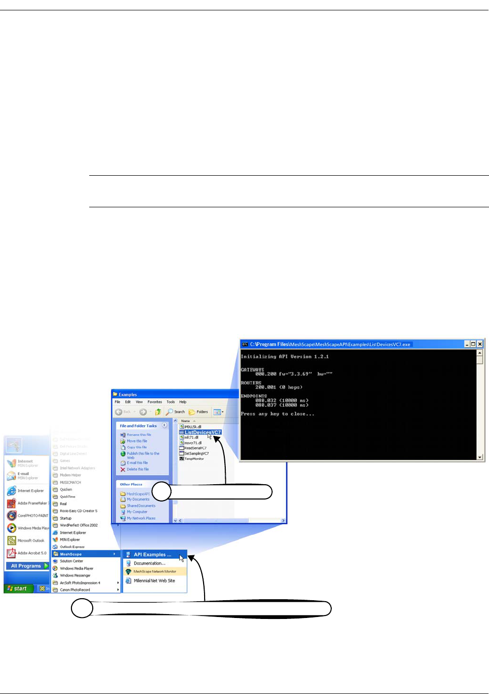
4-42 Millennial Net
Using the MeshScape API
Example API Code
Millennial Net provides as part of the reference kit, several example API applications. This
section examines in detail one of the API examples, ListDevicesVC7, including the code it uses.
ListDevicesVC7 provides a list of all detected network nodes (MeshGate, Mesh Node(s), and End
Node(s)).
ListDevicesVC7 Example
To run the ListDevicesVC7 example (see Figure 2.):
1. From the Windows taskbar, select the following to open the Examples window:
Start>All Programs>MeshScape>API Examples
2. From the Examples window, select ListDevicesVC7. The command window opens and
displays the list of detected network nodes.
Proceed to “ListDevicesVC7 Code” to view the code used in this example.
Figure A-2. API example: ListDevicesVC7
Note: Be sure that MeshScape Network Monitor is running before executing the following
procedure.
Select Start>All Programs>MeshScape>API Examples
1
Select ListDevicesVC7
2

RK-5409-5 Reference Kit User’s Guide 4-43
Example API Code
ListDevicesVC7 Code
The C file containing the code shown here can be found in the Programs directory:
Programs\MeshScape\examples\src\ListDevices
/*
* ListDevices.c
*
* Copyright (c) 2000-2005 Millennial Net, Inc. All Rights Reserved.
* Reproduction or modification is strictly prohibited without express
* written consent of Millennial Net.
*
* This example illustrates the basic operations of connecting to the i-Bean
* API and obtaining basic information about the devices in the network.
* It prints out the list of gateways, mesh nodes, and end nodes currently
* participating in the network, along with some information about each
* device.
*
* This project was built using Microsoft Visual C++ version 7.1, but should
* be compatible with other similar compiler versions.
*/
#include <iBeanAPI.h>
#include <iBeanAPI_IO.h>
#include <iBeanAPI_Utils.h>
#include <stdio.h>
#include <stdlib.h>
#ifndef __GNUC__
#include <conio.h>
#else
#include <mingw/conio.h>
/* #include <mingw/conio.h> */
#endif
/*
* This is the number of "words" in a network address. For example, the
* address "127.0.1" contains three words. The i-Bean protocol supports
* up to 8 words (64-bits), but the actual maximum is reduced in some
* product releases to optimize the packet size.
*/
#define MIN_DEVICEID_WORDS 3

4-44 Millennial Net
Using the MeshScape API
/***************************************************************************/
void WaitForKey(void) {
printf("\r\nPress any key to close...");
_getch();
printf("\r\n");
}
/****************************************************************************
* This is a simple wrapper for detecting and reporting API error return
* values. In C++, this function could throw an exception object.
*/
ibApi_RESULT CheckResult(ibApi_RESULT result) {
char error_text[256];
/*
* Error codes always have a negative value.
*/
if (result >= 0) return result;
/*
* For the purposes of this example, ibApi_RESULT_ERR_TIMEOUT is not a
* fatal error.
*/
if (result == ibApi_RESULT_ERR_TIMEOUT) return result;
/*
* This interprets the error code, writing the result to the error_text
* variable
*/
ibApi_Utils_GetErrorDescription(result,error_text,sizeof(error_text));
printf("\r\nERROR: %s\r\n",error_text);
/*
* Technically, ibApi_Close() should be called before exiting, e.g. via
* an atexit() handler. (This is omitted in the example for simplicity.)
*/
WaitForKey();
exit(1);
return 0;
}

RK-5409-5 Reference Kit User’s Guide 4-45
Example API Code
/***************************************************************************/
void ListDevices(ibApi_APIHANDLE api_hdl) {
#define DEVICEIDS_MAX 100
ibApi_GROUPID groupid;
ibApi_DEVICEID deviceids[DEVICEIDS_MAX];
int deviceids_count;
char deviceid_text[256];
int sampling_interval;
int i;
ibApi_DEVICEINFO deviceinfo;
ibApi_DEVICESTATUS devicestatus;
/*
* The ibApi_GetNetworkList() function returns a list of the groups
* currently managed by the network. If the gateway is not properly
* connected to the monitor, then this list will be empty.
*/
if (CheckResult(ibApi_GetNetworkList(api_hdl,&groupid,1) < 1)) {
printf("The network is empty\r\n");
return;
}
/*
* List the gateways in the group, which typically should be
* only one.
*/
printf("\r\nGATEWAYS\r\n");
deviceids_count = CheckResult(ibApi_GetDeviceList(api_hdl, groupid,
ibApi_DEVICETYPE_GATEWAY, deviceids,DEVICEIDS_MAX));
/*
* If the buffer limit was exceeded, then display partial results
*/
if (deviceids_count > DEVICEIDS_MAX)
deviceids_count = DEVICEIDS_MAX;
for (i=0; i<deviceids_count; ++i) {
/*
* Note that the struct_size must be assigned BEFORE calling
* ibApi_GetDeviceInfo(). This allows compatibility with future API
* versions that implement additional fields.
*/
deviceinfo.struct_size = sizeof(deviceinfo);

4-46 Millennial Net
Using the MeshScape API
CheckResult(ibApi_GetDeviceInfo(api_hdl,deviceids[i],&deviceinfo));
CheckResult(ibApi_Utils_ConvertDeviceIdToText(deviceids[i],
deviceid_text,sizeof(deviceid_text),MIN_DEVICEID_WORDS));
printf(" %10s fw=\"%s\" hw=\"%s\"\r\n", deviceid_text,
deviceinfo.firmware_version,deviceinfo.hardware_version);
}
/*
* List the mesh nodes.
*/
printf("\r\nROUTERS\r\n");
deviceids_count = CheckResult(ibApi_GetDeviceList(api_hdl, groupid,
ibApi_DEVICETYPE_ROUTER|ibApi_DEVICETYPE_ROUTERBEAN, deviceids,DEVICEIDS_MAX));
if (deviceids_count > DEVICEIDS_MAX)
deviceids_count = DEVICEIDS_MAX;
for (i=0; i<deviceids_count; ++i) {
/*
* Note that the struct_size must be assigned BEFORE calling
* ibApi_GetDeviceStatus().
*/
devicestatus.struct_size = sizeof(devicestatus);
CheckResult(ibApi_GetDeviceStatus(api_hdl,deviceids[i],&devicestatus));
CheckResult(ibApi_Utils_ConvertDeviceIdToText(deviceids[i],
deviceid_text,sizeof(deviceid_text),MIN_DEVICEID_WORDS));
printf(" %10s (%i hops)\r\n", deviceid_text, devicestatus.hop_count);
}
/*
* List the end nodes.
*/
printf("\r\nENDPOINTS\r\n");
deviceids_count = CheckResult(ibApi_GetDeviceList(api_hdl, groupid,
ibApi_DEVICETYPE_ENDPOINT, deviceids,DEVICEIDS_MAX));
if (deviceids_count > DEVICEIDS_MAX)
deviceids_count = DEVICEIDS_MAX;
for (i=0; i<deviceids_count; ++i) {

RK-5409-5 Reference Kit User’s Guide 4-47
Example API Code
CheckResult(ibApi_Utils_ConvertDeviceIdToText(deviceids[i],
deviceid_text,sizeof(deviceid_text),MIN_DEVICEID_WORDS));
sampling_interval = CheckResult(ibApi_GetSamplingInterval(api_hdl,deviceids[i]));
printf(" %10s (%i ms)\r\n", deviceid_text, sampling_interval);
}
}
/***************************************************************************/
int main() {
/*
* This handle represents the current API session.
*/
ibApi_APIHANDLE api_hdl;
ibApi_VERSION api_version;
api_version = ibApi_GetApiVersion();
printf("\r\nInitializing API Version %i.%i.%i\r\n\r\n",
ibApi_GET_VERSION_MAJOR(api_version),
ibApi_GET_VERSION_MINOR(api_version),
ibApi_GET_VERSION_RELEASE(api_version)
);
/*
* ibApi_Open() is called to begin the session. Your application
* should ensure that ibApi_Close() is called to release the handle
* before exiting.
*/
api_hdl = CheckResult(ibApi_Open(ibApi_EXPECTED_VERSION,"local",""));
ListDevices(api_hdl);
CheckResult(ibApi_Close(api_hdl));
WaitForKey();
return 0;
}

4-48 Millennial Net
Using the MeshScape API

RK-5409-5 Reference Kit User’s Guide A-1
A
Sample Application
This chapter contains information on how to perform the sample application included with the
RK-5409-5 Reference Kit:
•’Application Overview’ on page A-2
•’Application Setup & Operation’ on page A-4
•’Changing Temperature Sensor Battery’ on page A-7
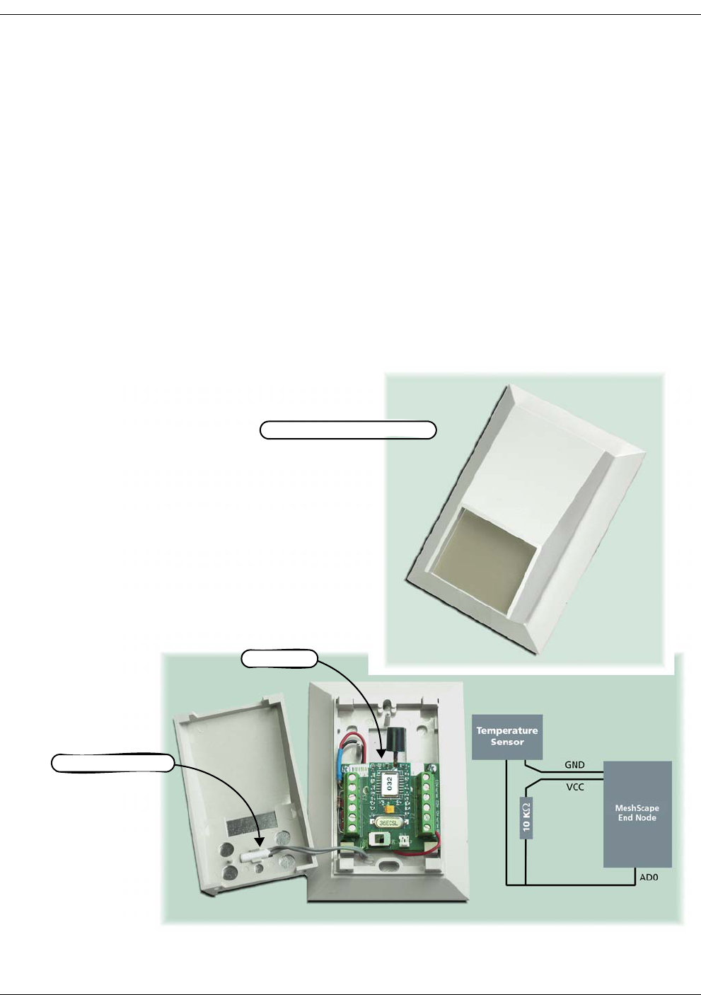
A-2 Millennial Net
Application Overview
Millennial Net includes a sample application in the RK-5409-5 Reference Kit. This application
demonstrates a real-world application of Millennial Net's end node peripheral interface and
how it is used for monitoring and data collection purposes across a wireless network.
The RK-5409-5 Reference Kit includes a temperature sensor assembly with a 10,000 Ohm Kele
sensor (Type 3) that changes resistance as its environmental temperature changes. The sensor
can be used to measure temperatures from -35O to +240O degrees Fahrenheit, with ±5%
accuracy.
The sensor's resistance change is measured via voltage change, measured by an end node's
ADC channel 0, and converted by the TempMonitor application software (included with kit) to
temperature. The sensor connection diagram is shown in Figure A-1 and process flow is shown
in Figure 2.
Figure A-1. Temperature sensor assembly overview (cover removed)
Temperature sensor
end node
Temperature sensor assembly
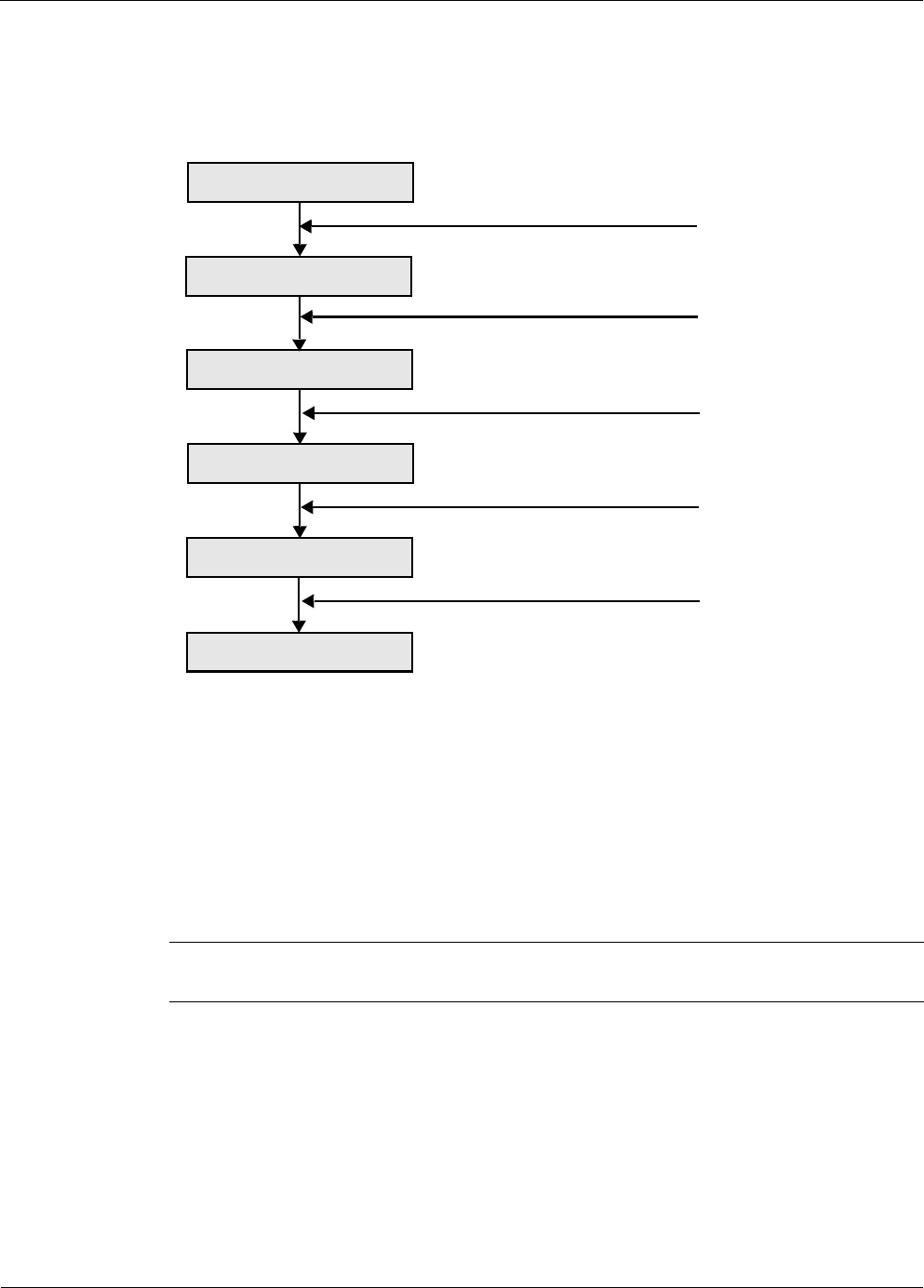
RK-5409-5 Reference Kit User’s Guide A-3
Application Overview
Figure A-2 describes the process flow.
Figure A-2. Process flow
Application Components
In addition to the MeshGate and MeshScape Network Monitor software supplied with the
RK-5409-5 Reference Kit, the following items are included for the sample application:
•end node (removed from one of the kit terminal boards)
•Temperature sensor assembly: This assembly contains a factory installed terminal board
and temperature sensor. The terminal board is also equipped with a factory-installed
battery for providing power to the end node.
•TempMonitor application software (automatically loaded on host PC when contents of
kit CD are installed)
Note: Before using the temperature sensor assembly for this sample application, you will
need to install an end node (see ’Temperature Sensor Assembly Setup’ on page A-4)
Temperature Change
Resistance Change
Voltage Change
ADC Reading Change
ADC Reading Change
Temperature Change
Temperature sensor
Closed circuit with power
ADC reading
Wireless network
TempMonitor application
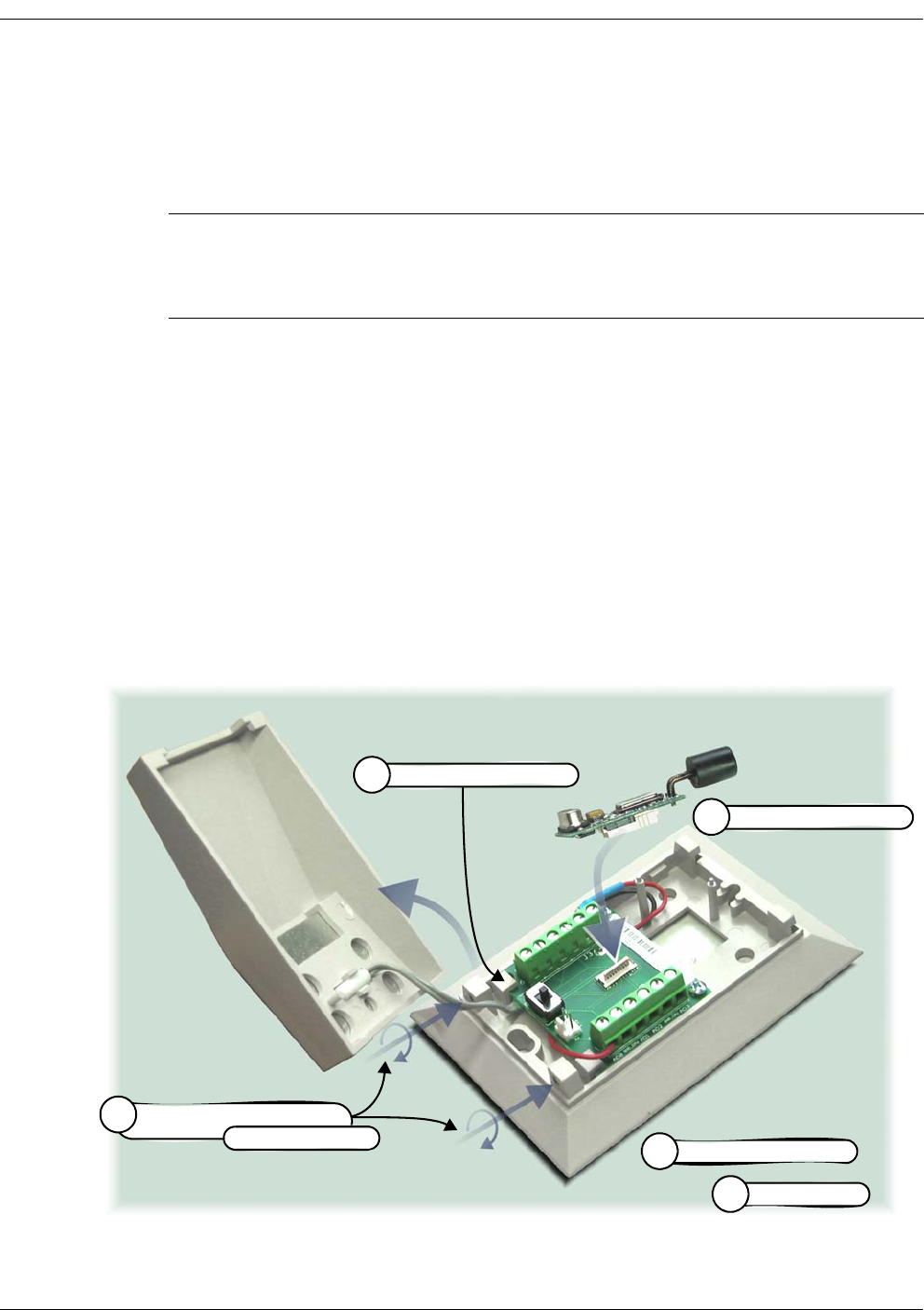
A-4 Millennial Net
Application Setup & Operation
The following procedures describe how to set up the RK-5409-5 Reference Kit hardware and
software for creating the Reference Kit’s sample application.
Temperature Sensor Assembly Setup
To install an end node in the temperature sensor assembly (see Figure A-3):
1. Use an Allen wrench to turn in the two set screws holding the cover to the base and
remove the cover.
2. Turn the Power Switch OFF.
3. Remove an end node from one of the kit’s terminal boards and install it on the terminal
board located on the base of the temperature sensor assembly.
4. Turn the Power Switch to ON. The sensor is discovered and displayed by MeshScape
Network Monitor.
5. Replace the cover and back out the two cover set screws to secure the cover in place.
Figure A-3. Installing end node in temperature sensor assembly
Note: Before this sample application can be executed, you must install the RK-5409
Reference Kit’s hardware and software according to the instructions found in
Chapter 2, “Installing the MeshScape System”. The MeshGate must be installed and
powered on, and MeshScape Network Monitor must be running before proceeding.
Install end node
3
Turn Power Switch ON
4
Turn Power Switch OFF
2
Replace cover
5
Turn in cover set screws (2),
1
then remove cover
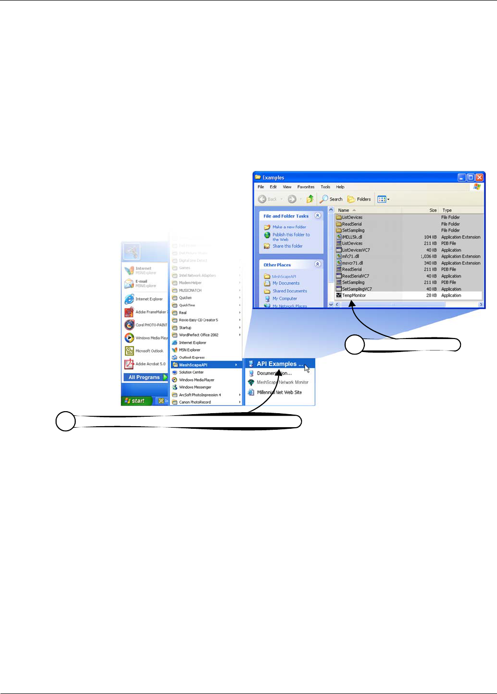
RK-5409-5 Reference Kit User’s Guide A-5
Application Setup & Operation
Launching TempMonitor Application
To launch the TempMonitor application (see Figure A-4):
1. From the Windows task bar, select Star>All Programs>MeshScape>API Examples.
The Examples window opens with a list of options.
2. Select TempMonitor from the Examples window. TempMonitor launches.
Figure A-4. Launching TempMonitor
Select Start>All Programs>MeshScape>API Examples
1
Select Te mp Mo n it or
2
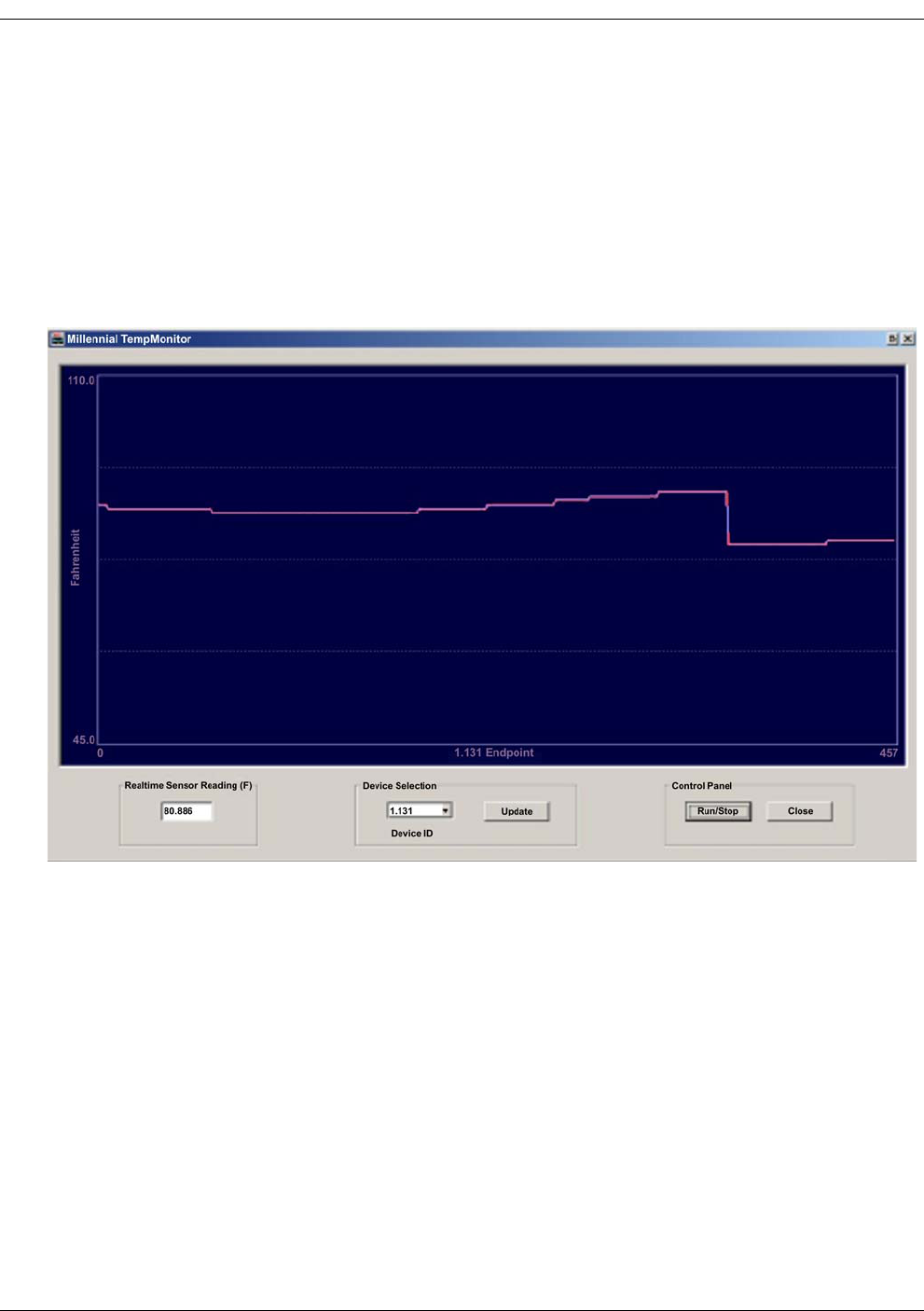
A-6 Millennial Net
TempMonitor Overview
The TempMonitor application displays temperature changes vs. time for one device only. Use
the Device Selection area to select the end node with matching device ID, then click Update
button to configure the device (enable ADC channel 1). The Run/Stop button is used to control
the display curve updating; Run means continuously update the curve, Stop means to freeze
the current curve. The precise reading can also be obtains from the Realtime Sensor Reading(F)
area.
Figure A-5. TempMonitor display
You can change the environment temperature to observe changes to the graph’s curve.
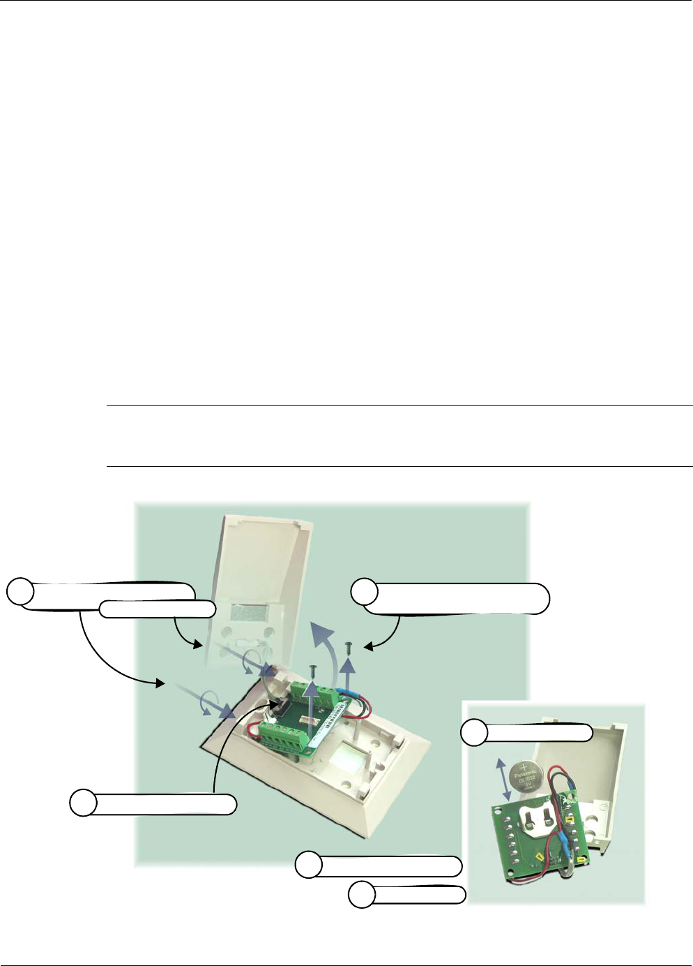
RK-5409-5 Reference Kit User’s Guide A-7
Changing Temperature Sensor Battery
Changing Temperature Sensor Battery
The temperature sensor assembly comes with a factory installed lithium battery. The procedure
below describes how to replace the battery when needed. Millennial Net recommends using
the following replacement battery type:
DigiKey Part Number: P189-ND.
To replace the battery (see Figure A-6):
1. Use an Allen wrench to turn in the two set screws holding the cover to the base and
remove the cover.
2. Turn the power switch OFF.
3. Remove the screws (2) securing the terminal board to the base and lift the terminal up
and off the base.
4. Replace the battery—located on the bottom of the terminal board—with the
recommended battery type, observing polarity (+ side of battery to + side of holder).
5. Turn the power switch ON.
6. Reinstall the terminal board, replace assembly cover, and back out the two cover set
screws to secure the cover in place.
Figure A-6. Changing temperature sensor assembly battery
Caution
Do not overtighten the terminal board mounting screws, which may damage the battery holder.
Replace battery
4
Turn power switch ON
5
Turn power switch OFF
2
Turn in cover set screws (2),
1
then remove cover
Remove mounting screws (2)
and terminal board
3
Replace cover
6

A-8 Millennial Net

RK-5409-5 Reference Kit User’s Guide B-1
B
Performing Firmware Upgrades
and Configuring Device IDs
The MeshScape Programmer application supplied with your RK-5409-5 Reference Kit enables
you to upgrade the firmware on your MeshGates and mesh nodes, and re-program the group
and device IDs on your MeshScape System. The supplied End Node Configurator enables you to
program the group and devices IDs, default sample interval, and statistics reporting rate on end
nodes. This chapter contains information on how to use the MeshScape Programmer and End
Node Configurator applications and includes:
•’Getting Started with MeshScape Programmer’ on page B-2
•’Performing MeshScape Programmer Operations’ on page B-4
•’Getting Started with End Node Configurator’ on page B-8
•’Performing End Node Configurator Operations’ on page B-10

B-2 Millennial Net
Getting Started with MeshScape
Programmer
MeshScape Programmer is a feature-rich application that enables you to upgrade your
MeshScape system by:
• re-programming the device flash memory
• unlocking firmware feature upgrades
• re-programming group and device IDs
To use MeshScape Programmer, you will need to:
• connect the target device that you wish to upgrade to your computer
• run the MeshScape Programmer application on your computer
Connecting the Target Device to Your Computer
You may upgrade the firmware on a MeshGate or a mesh node using MeshScape Programmer.
Connecting a MeshGate for Programming
The MeshGate provides a console port equipped with a mini-connector to facilitate firmware
upgrades.
Using the mini-connector-to-nine-pin serial connector cable supplied in your RK-5409-5
Reference Kit, connect the MeshGate console port to the serial port on your computer.
Connecting a Mesh Node for Programming
1. Connect a MeshGate to your computer as described above.
2. Remove the connector panel access cover from the MeshGate connected to the
computer and remove the chassis cover from the target mesh node.
3. Referring to Figure B-1 and using the supplied MeshGate programming cable and
MeshGate-to-mesh node adapter, connect the external programming port on the
MeshGate to port SL-7 on the mesh node.
4. Replace the MeshGate connector panel access cover and mesh node chassis cover, and
disconnect the programming cable after the firmware update is complete.
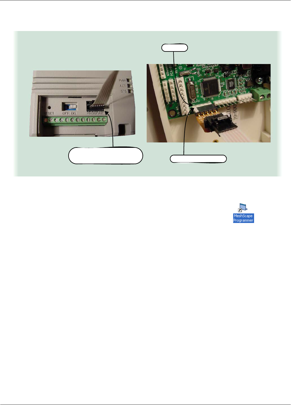
RK-5409-5 Reference Kit User’s Guide B-3
Getting Started with MeshScape Programmer
Figure B-1.Connecting MeshGate programming cable w/adapter to mesh node
Launching MeshScape Programmer Using Windows
To launch MeshScape Programmer, do one of the following:
– Double-click on the desktop’s MeshScape Programmer icon.
– From the Windows taskbar, select:
Start>All Programs>MeshScape Programmer>MeshScape Programmer.
MeshScape Programmer runs as described in the next section.
SL-7 on Mesh Node
External Programming Port
on MeshGate
Pin 1
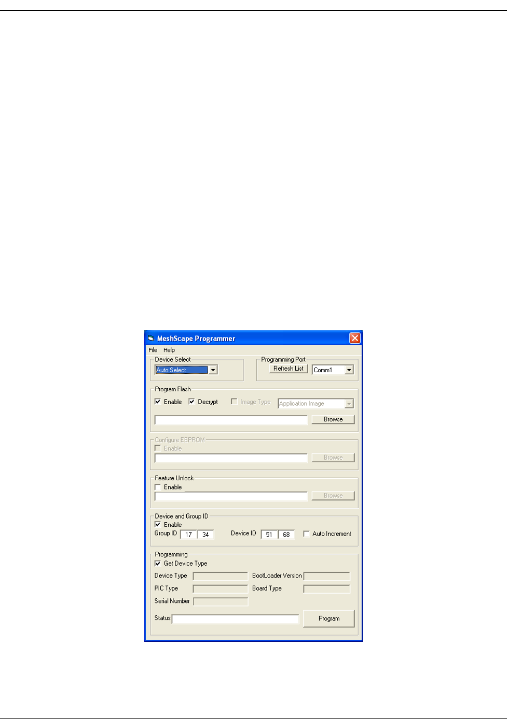
B-4 Millennial Net
Performing MeshScape Programmer
Operations
You may use MeshScape Programmer to:
• upgrade the firmware image on the target device
• unlock features on the target device
• re-program the device and group IDs on the target device
Upgrading Firmware on the Target Device
To upgrade the firmware on a MeshGate or mesh node using the MeshScape Programmer
application:
1. Connect the target device to your computer and launch the MeshScape Programmer
application as described in the previous section.
The MeshScape Programmer main window appears as shown in Figure B-2.
Figure B-2.The MeshScape Programmer main window

RK-5409-5 Reference Kit User’s Guide B-5
Performing MeshScape Programmer Operations
2. Select the target device to program by selecting an option from the Device Select
drop-down menu:
– Auto-Select - Allow MeshScape Programmer to determine the connected device type
(default).
– MeshGate Application - Upgrade the firmware on the MeshGate’s main application terminal
board.
– MeshGate RF - Upgrade the firmware on the MeshGate’s RF daughter board.
– External Device - Upgrade a mesh node connected to the MeshGate.
3. Select the PC serial port to use when communicating with the connected MeshGate from
the Programming Port drop-down menu.
If a required Comm port is being used by another application, close the application and
then click Refresh List to make the Comm port available for use by MeshScape
Programmer.
4. Select the firmware image file to load on the target device.
a. Mark the Enable checkbox to enable the program flash operation.
b. Mark the Decrypt checkbox to decrypt an encrypted image file. Encrypted image
files are denoted by a .enc file extension.
c. Click the Browse button, and select the firmware image file supplied to you from
Millennial Net.
5. Upload the new image file to the target device.
a. Mark the Get Device Type checkbox to display information about the target
device in the Device Type field as the upgrade progresses.
b. Click Program to initiate the firmware upgrade.
As the firmware upgrade progresses, you will see status messages posted to the Status field.
Once the upgrade is completed, the status will be reported as Programming Complete.
Unlocking Features on the Target Device
To unlock features on a MeshGate or mesh node using the MeshScape Programmer application:
1. Connect the target device to computer and launch the MeshScape Programmer
application as described on page B-2.
The MeshScape Programmer main window appears as shown in Figure B-2.
2. Select the target device to program by selecting an option from the Device Select
drop-down menu:
– Auto-Select - Allow MeshScape Programmer to determine the connected device type
(default).
– MeshGate Application - Upgrade the firmware on the MeshGate’s main application terminal
board.
– MeshGate RF - Upgrade the firmware on the MeshGate’s RF daughter board.
– External Device - Upgrade a mesh node connected to the MeshGate.

B-6 Millennial Net
3. Select the PC serial port to use when communicating with the connected MeshGate from
the Programming Port drop-down menu.
If a required Comm port is being used by another application, close the application and
then click Refresh List to make the Comm port available for use by MeshScape
Programmer.
4. Select the feature unlock file to load on the target device.
a. Mark the Enable checkbox to enable the feature unlock operation.
b. Click the Browse button, and select the feature unlock file supplied to you from
Millennial Net.
5. Upload the feature unlock file to the target device.
a. Mark the Get Device Type checkbox to display information about the target
device in the Device Type field as the upgrade progresses.
b. Click Program to initiate upload of the feature unlock file to the target device.
As the feature unlock file upload progresses, you will see status messages posted to the Status
field. Once the update is completed, the status will be reported as Programming Complete.
Reprogramming the Group and Device IDs on the Target Device
To reprogram the group and device IDs on a MeshGate or mesh node using the MeshScape
Programmer application:
1. Connect the target device to computer and launch the MeshScape Programmer
application as described on page B-2.
The MeshScape Programmer main window appears as shown in Figure B-2.
2. Select the target device to program by selecting an option from the Device Select
drop-down menu:
– Auto-Select - Allow MeshScape Programmer to determine the connected device type
(default).
– MeshGate Application - Upgrade the firmware on the MeshGate’s main application terminal
board.
– MeshGate RF - Upgrade the firmware on the MeshGate’s RF daughter board.
– External Device - Upgrade a mesh node connected to the MeshGate.
3. Select the PC serial port to use when communicating with the connected MeshGate from
the Programming Port drop-down menu.
If a required Comm port is being used by another application, close the application and
then click Refresh List to make the Comm port available for use by MeshScape
Programmer.
4. Enter the group and device IDs to set on the target device.
a. Mark the Enable checkbox to enable the ID reprogramming.

RK-5409-5 Reference Kit User’s Guide B-7
Performing MeshScape Programmer Operations
b. Enter the new IDs in the Group ID and Device ID fields.
c. Optional. Mark the Auto Increment checkbox if you will be reprogramming the
group and device IDs on multiple devices and wish to do so in sequence.
5. Upload the new group and device IDs to the target device.
a. Mark the Get Device Type checkbox to display information about the target
device in the Device Type field as the upgrade progresses.
b. Click Program to initiate upload of the new IDS to the target device.
As the group and device ID reprogramming progresses, you will see status messages posted to
the Status field. Once the update is completed, the status will be reported as Programming
Complete.
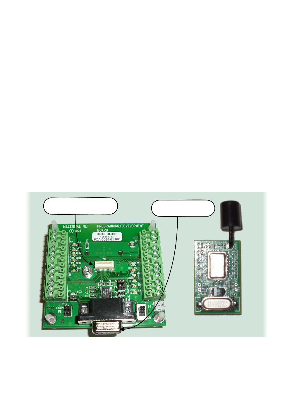
B-8 Millennial Net
Getting Started with End Node
Configurator
End Node Configurator is a feature-rich application that enables you to upgrade your
MeshScape end nodes by programming:
• group and devices IDs
• default sample interval
• statistics reporting rate
To use End Node Configurator, you will need to:
• connect the target end node that you wish to upgrade to your computer
• run the application on your computer
Connecting the Target End Node to Your Computer
A special terminal board equipped with an RS-232 serial port is included in your Reference Kit
for programming end nodes. This end node terminal board is shown in Figure B-3.
Figure B-3.Connecting an end node to the programming terminal board
To connect an end node to your computer for programming:
1. Connect the end node to connector P11 on the end node programming terminal board.
2. Connect the supplied RS-232 serial cable between the terminal board and the host PC on
which you will be running the End Node Configurator application.
Connect RS-232 Cable
to PC Here
Connect End Node to
P11

RK-5409-5 Reference Kit User’s Guide B-9
Getting Started with End Node Configurator
Launching End Node Configurator Using Windows
To launch End Node Configurator, do one of the following:
– Double-click on the desktop’s End Node Configurator icon.
– From the Windows taskbar, select:
Start>All Programs>End Node Configurator.
End Node Configurator runs as described in the next section.
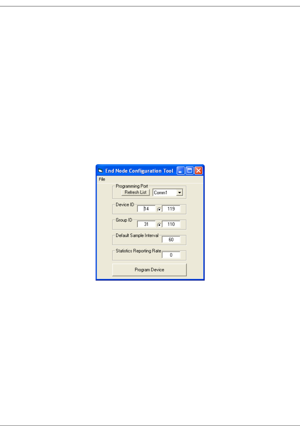
B-10 Millennial Net
Performing End Node Configurator
Operations
You may use End Node Configurator to program an end node’s:
• group and devices IDs
• default sample interval
• statistics reporting rate
To use End Node Configurator:
1. Connect the target end node to your computer and launch the End Node Configurator
application as described in the previous section.
The End Node Configurator main window appears as shown in Figure B-4.
Figure B-4.The End Node Configurator main window
2. Select the PC serial port to use when communicating with the connected end node from
the Programming Port drop-down menu.
If a required Comm port is being used by another application, close the application and
then click Refresh List to make the Comm port available for use by End Node
Configurator.
3. Enter the device ID you wish to program on the end node in the Device ID field.
The device ID is used to uniquely identify each device within a MeshScape system.
4. Enter the group ID you wish to program on the end node in the Group ID field.
The group ID is the network ID used to identify members of the same MeshScape
system.
5. Enter how often the end node transmits a ‘heart beat’ data packet or any other data in
the Default Sample Interval field.

RK-5409-5 Reference Kit User’s Guide B-11
Performing End Node Configurator Operations
The default end node sample interval setting is 60 seconds.
6. Enter the rate at which the end node sends statistics in the Statistics Reporting Rate
field.
The Statistics Reporting Rate is the number of normal packets transmitted before
performance statistics are added to a packet.
A Statistics Reporting Rate of 0 means every packet has performance statistics added
to it. A Statistics Reporting Rate of 1 means 1 normal packet is transmitted then
performance statistics are added to a packet. A Statistics Reporting Rate of 2 would
mean 2 normal packets are transmitted and the next packet has performance
statistics added to it.
The maximum Statistics Reporting Rate is 254.
The default setting is 0—every packet has performance statistics added to it.
7. Click Program to program the end node with the entered settings.

B-12 Millennial Net

RK-5409-5 Reference Kit User’s Guide Glossary-1
Glossary
API Application Programming Interface: A set of definitions of the ways in which
one piece of computer software communicates with another. It is a method of
achieving abstraction, usually (but not necessarily) between lower-level and
higher-level software. One of the primary purposes of an API is to provide a set
of commonly used functions-for example, to poll a wireless network for active
network nodes (mesh nodes and end nodes). Programmers can then take
advantage of the API by making use of its functionality, saving them the task of
programming everything from scratch. APIs themselves are abstract: software
that provides a certain API is often called the implementation of that API.
ad hoc network A group of wireless sensors connected as an independent wireless network,
communicating directly with each other without the use of a mesh node.
bandwidth The amount of data that can be transmitted in a fixed amount of time. For
digital devices, the bandwidth is usually expressed in bits per second (bps) or
bytes per second. For analog devices, the bandwidth is expressed in cycles per
second, or Hertz (Hz).
data model As it pertains to wireless sensor networks, the data model characterizes and
describes the way in which data flows through and is used in the network.
Common data model categories include data collection models (periodic
sampling, event driven, and store and forward) and bi-directional dialogue data
models (polling and on demand).
DSSS Direct Sequence Spread Spectrum: Spread spectrum method of spreading a
narrow band signal. This method uses special pseudo noise codes to expand the
narrow band signal out across a broad portion of the radio band. (See also FHSS
and spread spectrum.)
duty cycle The duty cycle of a module refers to the percentage of time the module is active
versus inactive.
end node The network module that provides the physical interface between the wireless
sensor network and the sensor or actuator that it is wired to. Sometimes called a
Reduced Function Device (see RFD).
endpoint See end node.
FFD Full Function Device: A term referring to a device that can act as an intermediate
mesh node, passing data from other devices. (See also RFD.)

Glossary
Glossary-2 Millennial Net
FHSS Frequency Hopping Sequence Spread Spectrum: Spread spectrum method of
spreading a narrow band signal out across a broad portion of the radio band.
This method “hops” the signal as a function of time. (See also DSSS and spread
spectrum.)
gateway The network module that provides the interface between the application
platform and the modules on the wireless sensor network.
IEEE Institute of Electrical and Electronics Engineers: Organization of engineers,
scientists, and students that is known for developing standards for the computer
and electronics industry.
IEEE 802.11.4 Standard developed by IEEE that defines the lower protocol layers (PHY and
MAC) for low-data-rate wireless Personal Area Networks (PANs).
ISM The industrial, scientific, and medical (ISM) radio bands were originally reserved
internationally for non-commercial use of RF electromagnetic fields for
industrial, scientific and medical purposes. They are now also used for
license-free error-tolerant wireless communications applications in the 900 MHz
and 2.4 GHz bands.
latency In networking, the amount of time it takes a packet to travel from source to
destination. Together, latency and bandwidth define the speed and capacity of a
network.
mesh node The module on the wireless sensor network used to extend network coverage
area, route around obstacles, and provide back-up routes in case of network
congestion or device failure. The mesh node can also provide a direct physical
interface to a sensor or actuator. Sometimes called a Full Function Device (see
FFD).
mesh topology A wireless sensor networking architecture consisting of a gateway and mesh
nodes that provides extended area coverage, routing around obstacles, and
back-up data paths.
narrowband Radio signal that contains all of its power within a very narrow portion of the
radio frequency band.
OSI Open System Interconnection: An ISO standard for worldwide communications
that defines a networking framework for implementing protocols in seven
layers. Control is passed from one layer to the next, starting at the application
layer in one station, proceeding to the bottom layer, over the channel to the next
station and back up the hierarchy.
packet A piece of a message transmitted over a packet-switching network. One of the
key features of a packet is that it contains the destination address in addition to
the data.

Glossary
RK-5409-5 Reference Kit User’s Guide Glossary-3
personal area
network
A personal area network (PAN) is the interconnection of information technology
devices within the range of an individual person, typically within a range of 10
meters.
protocol The protocol defines a common set of rules and signals that devices (nodes) on
the network use to communicate.
protocol stack A set of network protocol layers that work together. The OSI reference model
that defines seven protocol layers is often called a stack.
RFD Reduced Function Device: A term referring to a device that is just smart enough
to talk to the network (see also FFD).
router See mesh node.
sensor node A wireless sensor network node consisting of a sensor or actuator device
attached to a wireless module. The wireless module provides the interface
between the sensor device and the wireless network.
SNR Signal-to-noise ratio: the ratio of the amplitude of a desired analog or digital
data signal to the amplitude of noise in a transmission channel at a specific point
in time. SNR is typically expressed logarithmically in decibels (dB). SNR measures
the quality of a transmission channel or an audio signal over a network channel.
The greater the ratio, the easier it is to identify and subsequently isolate and
eliminate the source of noise. A SNR of zero indicates that the desired signal is
virtually indistinguishable from the unwanted noise.
spread spectrum
(wideband)
Technique for taking a narrowband signal and spreading it across a broader
portion of the radio frequency band. Spread-spectrum signals are more resistant
to interference than narrow band signals. The two basic methods for spreading
a narrowband are direct sequence and frequency hopping. (See also DSSS and
FHSS.)
star topology A wireless sensor networking architecture consisting of a gateway and end
nodes that is extremely power efficient for short-range networks.
star-mesh hybrid
topology
A wireless sensor networking architecture consisting of a gateway, mesh nodes,
and end nodes that optimizes range and power efficiency of the network.
topology As it pertains to wireless sensor networks, the geometric arrangement of the
modules (gateway, mesh nodes, and end nodes) within a network. Common
topologies include star, mesh, and star-mesh hybrid.

Glossary
Glossary-4 Millennial Net

RK-5409-5 Reference Kit User’s Guide Index-1
Index
A
AD converter
configuring 3-14
API code, example 4-42
API directory structure 4-3
API functions, overview of 4-5
API, using the MeshScape 4-2
audience for this document xvi
B
bin directory 4-3
burst, data model 1-9
C
com port
selecting on host PC 3-21
compliance statement, FCC and RSS-210 v
configuring
ADC 3-14
digital I/O 3-9
RS-232 3-15
RS-485 3-16
sample interval 3-8
UART operation 3-12
customer support, contacting xviii
D
data format
configuring (serial and ADC) 3-22
data models, supported by MeshScape 1-7
default settings
end node 2-13
mesh node 2-8
MeshGate 2-6
Device window 3-6
digital I/O
configuring 3-9
digital input setup 3-9
digital output setup 3-10
DIN rail, mounting MeshGate to 2-5
doc directory 4-3
E
e-mail address for support xviii
end node, function of 1-5
ESD warning 1-12
event driven, data model 1-8
event log file
creating 3-26
viewing 3-27
examples directory 4-3
F
FCC compliance statement v
firmware, upgrading B-1
frequency band 1-11
functions, MeshScape API 4-5
G
gateway, function of 1-5
H
hardware installation 2-3
host PC requirements 1-12
I
iBeanAPI.h 4-7
iBeanAPI_IO.h 4-23
iBeanAPI_LPR.h 4-36
iBeanAPI_performance.h 4-39
iBeanAPI_Utils.h 4-32
include directory 4-4
install
end node 2-12
mesh node 2-7
MeshGate gateway 2-3
MeshScape Network Monitor 2-14
L
labeling nodes 3-19
lib directory 4-4
Low power configuration 1-9
M
major features of MeshScape 1-11
mesh node, function of 1-5
MeshScape Network Monitor
configuring node’s operation 3-6
counts 3-4
install software 2-14
menu bar 3-3
MeshGate gateway details 3-4
monitoring features 3-2
overview 3-2
sensor node details 3-4
MeshScape programmer application B-1
MeshScape system overview 1-6
Millennial Net, contacting xviii
monitoring statistics 3-29

Index
Index-2 Millennial Net
N
node status 3-4
O
on-demand, data model 1-8
organization of this document xvi
P
periodic sampling, data model 1-7
persistence
configuring 3-20
persistent dynamic routing™ technology 1-6
polling, data model 1-8
R
reference kit
contents 1-11
RS-232
configuring on mesh node 3-15
RS-485
configuring on mesh node 3-16
RSS-210 compliance statement v
S
sample application A-2
sample application overview A-2
sample interval
all nodes 3-8
single node 3-8
serial communication parameters 3-12
store and forward, data model 1-8
stream, data model 1-9
symbols and conventions xvii
system software, MeshScape 1-3
T
temperature sensor assembly
change battery A-7
overview A-2
setup A-4
TempMonitor
launching A-5
overview A-6
U
UART
configuring 3-12
upgrading firmware B-1
W
Watch
function 3-17
window 3-17
wireless sensor network resources, additional xviii
wireless sensor networks
compondents of 1-3
overview of 1-2
world-wide-web address xviii