Miller Edge MDTR3 CONTROL ALARM TRANSMITTER User Manual OYE MDTR3 UserMan
Miller Edge, Inc. CONTROL ALARM TRANSMITTER OYE MDTR3 UserMan
Users Manual

Miller Edge, Inc.
Monitored Device
Radio
MW-MDTR-20
315 MHz
Transmitter
FCC ID: OYE-MDTR3
TRADE NAME: Miller Edge
MODEL: ME-MDTX-20
This device complies with Part 15 of
the FCC Rules. Operation is subject to
the following two conditions:
(1) this device may not cause harmful
interference, and (2) this device must
accept any interference received,
including interference that may
cause undesired operation.

Installation Instructions for
Miller Edge Inc
.
Monitored Device Ping Radio
MW-MDTX-20 and MW-MDRX-20
Kit Contents:
1. MW-MDTX-20
Transmitter Unit
2. (2) AA Lithium Batteries
3. MW-MDRX-20
Receiver Unit
4. Receiver Antenna
Customer Supplied:
1. Terminated Edge
(or Device)
2. Source of 12 to 24V AC
or DC, @ 100mA, min.
1
Tools Required:
1. 3/32” Flat blade screwdriver
2. ¼” Flat blade screwdriver
3. #1 Philips Head screwdriver
4. Optional VOM
for test purposes
5. Mounting screws
(as required)
Transmitter Test and Installation:
Step 1. Open and unpack the
transmitter and receiver unit.
Unpack the antenna and batteries.
Unpack the optional receiver
wiring harness.
2
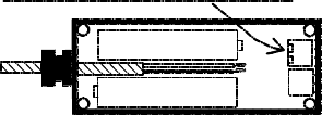
Step 2. Remove the Transmitter
cover (using the ¼” Flat screw-
driver) and place the cover to the
left of the unit for reference.
Step 3. Remove the Transmitter
PCB from the enclosure using the
#1 Philips screw driver on the 4
corner screws.
Step 4. Route the cable from the
monitored device (Edge) through
the cable gland for approximately
four inches.
Strip 2” of sheathing from the
cable end.
Strip the insulation from the
two wires back ½”.
Twist the wires to tighten the
strands and fold each back ¼”.
See Fig. 1.
3

Step 5. Place the two AA
Lithium batteries in their holders
paying attention to their polarity.
Note: A wrongly installed battery
will not do harm to the unit but
the transmitter will not operate,
and the PCB will have to be
removed to correct the error.
Step 6. Tuck the wires
connected to the SE terminal
block neatly between the
batteries and pull the excess
wire back through the cable
gland; re-seat the PCB and
replace the 4 mounting screws.
Tighten the cable gland.
Step 7. Set the Termination
Device switch to either 10K
resistive, or 9.1V Diode. This
selection must match the
Safety Edge Termination type.
4
Step 8. Transmitter Quick Test:
Set the Tx/Rx Group and Address
switches to the desired positions.
If the Group switch is set to 0,
the address switch may be set to
any position between 0 and F.
If the Group switch is set to 1,
the Address switch may be set
to any position between 0 and B.
The remaining positions, C, D, E,
and F are reserved for factory
testing.
Momentarily press the TEST
button to load the address and
group data.
5
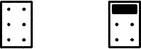
The Red and Green LEDs used
to indicate Tx Data and Low
Battery condition will flash
momentarily during the power
on sequence (when the
batteries are installed). The
Green Tx Data LED should flash.
The Red Low Battery LED will
only light when the batteries
fall below 2.4v.
Note: Low Battery data is also
sent to the receiver and
displayed there.
Step. 9 Replace the cover on
the Transmitter. Tighten the
screws.
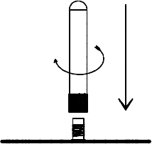
Step 10. Mount the Transmitter
on the bottom bar of the door.
6
The mounting holes are located
under the cover mounting screws.
The transmitter must be mounted
with it’s top cover facing upward.
Fig. 1
CONNECT SAFETY EDGE WIRES TO 'SE'
KO
SE
7
Receiver Installation and Test:
Step 1. Remove the cover from the
Receiver Unit (MW-MDRX-20)
and place it alongside of the
receiver.
Step 2. Route the wires from the
operator source (12 to 24v AC/DC)
to the Power Terminal block on the
receiver. The power input is
polarity independent and accepts
either AC or DC. Note: An external
wall transformer may be used if
12 – 24 VAC/DC is not available
from the operator unit.
Step 3. Set the Rx Group and
Address switches to match the
transmitter switch settings.
8
Step 4 Connect the antenna to
the receiver RF board. See Fig. 2.
Step 5 The termination header
has a jumper that can be pulled
straight up and re-inserted into
the proper position. Set the
termination selection jumper to
either 10K resistive or 9.1V
Diode. See Fig.3.
Step 6 Preliminary Test Check:
Confirm that the Transmitter is ON,
and power to the receiver is ON.
(Confirm that the Blue LED Power
light is On.)
Activate the Safety Edge (or
monitored device) and check that
the Address Valid (Yellow LED)
is ON.
IF the Address Valid LED is not on,
check that the Group and Address
switches match the transmitter’s
switch settings
9
Check that the Photo-Eye and
Safety-Edge LEDs (red and green
respectively) are lit.
Clear the Edge (or safety device)
and note that the Photo-eye and
Safety Edge LEDs go OFF.
Step 7. If the above tests pass,
mount the receiver close to the
operator and in the line-of-sight of
the transmitter. Proceed to
connect the receiver’s SE or PE
output to the operator.
Step 8. Operator - Safety Device
Test: Confirm UL operator require-
ments for momentary pressure
operators.
Fig. 2
10
Functional Door Test:
Idle Indications, NO problems:
Tx No lights ON
Rx Only Blue LED (power) ON
PRESS & HOLD the Safety Edge:
Tx A brief blink of Green LED
Rx A brief blink of Yellow LED
Red (PhotoEye) LED ON
Green (Safety Edge)LED ON
and, after a second,
Red (Ping Loss) LED comes ON
RELEASE the safety Edge:
Tx A brief blink of Green LED
Rx A brief blink of Yellow LED
Red (PhotoEye) LED is OFF
Green (SafetyEdge) LED is OFF
and, after 1-2 seconds,
Red (PingLoss) LED is OFF
11
Preliminary Specifications:
RF Frequency 315 MHz
Modulation OOK
Data Rate 19.2Kbps
Discrete addresses 28
Tx to Rx Range 3’ – 100’
Enclosure polycarbonate
Transmitter:
Tx Battery Li/FeS
2
(Energizer L91, 2- AA cells)
Avg. Battery Life, 23°C: 12 Months
Operating Voltage: 2.2V to 3.6V
Operating Temp.: -40°F to 140°F
Operating Humidity: 0 to 100%
12
Mounting: 4 - #6 self-tap screws
Size: 5 5/8” x 1 ¾” x 1 ¾”
Antenna: Integral helical ¼ λ
Indicators: (2)
low battery/test mode (Red)
transmission ON (Green)
Input Connections:
Safety Edge sensor, 2 wire;
w/switch selectable termination:
(10KΩ or 9.1V TVS diode)
Knock Out sensor; N/O or N/C
Input connectors:
Terminal Block, 16 to 26 AWG
13
Receiver:
Operating Voltage: 12-24 VAC/DC
@ 100 mA, max.
Operating Temp. -40°F to 140°
Operating Humidity: 0 to 98%,
non-condensing
Size: L W H
4 5/8” x 3¾” x 1¼ ” + Ant.
(total height w/ antenna is 2 3/4”)
Antenna: helical, ¼ λ, SMA
Mounting: 2 - #6 self-tap screws
Indicators: (7)
Power On (Blue)
Address Valid (Yellow)
Ping Loss (Red)
Photo-Eye (Red)
Safety Edge (Green)
Knock Out (Green)
Low Battery (Green)
14
Operator Interface Connections:
Power, 12/24V input
S.E. PhotoEye output
S.E. Relay output
(S.E. Termination options;
10KΩ, 9.1V diode, none)
Knock Out Relay output
Low Battery Relay output
(all relays provide N/O & N/C)
Fig. 3
10K Resistor
9.1V Diode
10K R selected
unterminated
Future Use
15
This equipment has been
tested and found to comply
with the limits for a Class B
digital device, pursuant to
Part 15 of the FCC Rules.
These limits are designed to
provide reasonable protection
against harmful interference
in a residential installation.
This equipment generates,
uses and can radiate radio
frequency energy and, if not
installed and used in accord-
ance with the instructions,
may cause harmful interfer-
ence to radio communications.
However, there is no guaran-
tee that interference will not
occur in a particular installation.
If this equipment does cause
harmful interference to radio or
television reception, which may
be determined by turning the
equipment off and on, the user
16
is encouraged to try to correct
the interference by one or more
of the following measures:
1. Re-orient or relocate the
receiving antenna
2. Increase the separation
between the equipment and
receiver.
3. Connect the equipment
into an outlet on a circuit diff-
erent from that to which the
receiver is connected
4. Consult the dealer or an
experienced radio/TV
technician for help.
Changes Or Modifications
Not Expressly Approved By
The Party Responsible For
Compliance Could Void The
User’s Authority To Operate
The Equipment.
17