Miller Edge MTF10 RF Link User Manual WPE Instuctions
Miller Edge, Inc. RF Link WPE Instuctions
Contents
- 1. aw12 manual
- 2. aw14 manual
- 3. ps20 manual
ps20 manual
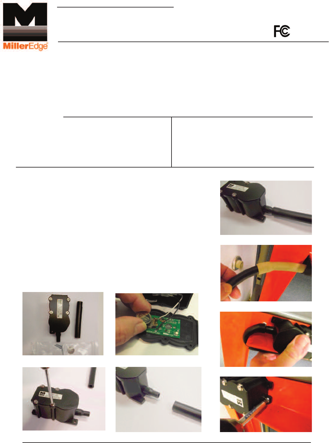
2-1. Open and unpack the battery and remove lid from the PS20-RF.
2-2. Install the CR2032 battery as shown with the “+” side up.
Notice that the RED LED blinks once upon insertion.
2-3. Replace the lid of the PS20-RF.
2-4. Insert the PS20-RF nipple into either end of the Hard Hose.
2-5. Insert remaining Hard Hose end into the Gum Rubber Hose
located inside the bottom astragal.
2-6. Position and attach the PS20-RF to the bottom angle or end stile
of the door, taking care not to pinch close the Hard Rubber
or Gum Rubber Hose.
P.O. Box 159 • West Grove, PA 19390 • 800-220-3343 • 610-869-4422 • Fax: 610-869-4423 • www.milleredge.com
6809 South Harl Ave., Suite A • Tempe, AZ 85283 • 800-887-3343 • 480-755-3565 • Fax: 480-755-3558
Model # PS20-RF
INSTALLATION INSTRUCTIONS
IMPORTANT:
READ AND UNDERSTAND ALL INSTRUCTIONS BEFORE BEGINNING INSTALLATION.
Parts List
1. PS20-RF Transmitter/Air Switch Combination
2. HRH-375, Hard Hose, 4”
3. Battery, CR2032
1-
PART NUMBER
2- Install Transmitter / Air Switch Assembly
Tools Required:
1. 1/8” Phillips Head Screwdriver
2. Mounting Screws (not supplied)
Pending
The PS20RF switch offers installation time savings and improved visual aesthetics as there is no need
to hard wire a coil cord or retracting reel. PS20RF switch includes a receiver which is wired to the motor
controls.
PS20 kits are available as either hard-wired (PS20A) or wireless (PS20RF) complete with receiver.
Kits may be installed on a doors up to 18 feet wide.
2-1 2-2
2-3 2-4
2-4
2-5
2-6
2-6
DRAFT

4- Transmitter Specifications
5- FCC Compliance
P.O. Box 159 • West Grove, PA 19390 • 800-220-3343 • 610-869-4422 • Fax: 610-869-4423 • www.milleredge.com
6809 South Harl Ave., Suite A • Tempe, AZ 85283 • 800-887-3343 • 480-755-3565 • Fax: 480-755-3558
Frequency: 915 MHz. FSK Modulation
Indicator Light: Red LED. Blinks when data is sent.
Power Source: CR2032 Coincell Battery 3.0VDC Lithium
Antenna: Integral PCB loop
Response Time: Nominal 100 msec, Safety Edge Input to Receiver Relay
Contact Output
Operating Distance: 50 feet minimum, Up to 100 feet depending on conditions
Operating Temperature: 14oF - 140oF (-10oC - + 60oC)
Transmitter
Model: PS20-RF
FCC ID: OYE-MTF10
THIS DEVICE COMPLIES WITH PART 15 OF THE FCC RULES.
OPERATION IS SUBJECT TO THE FOLLOWING TWO CONDITIONS:
1) THIS DEVICE MAY NOT CAUSE HARMFUL INTERFERENCE, AND
2) THIS DEVICE MUST ACCEPT ANY INTERFERENCE RECEIVED
INCLUDING INTERFERENCE THAT MAY CAUSE UNDESIRED OPERATION.
3- Test Safety Edge
3-1 Ensure that the door stops/reverses when the sensing edge
is activated during the close cycle.
Changes or Modifications Not Expressly Approved By The Party Responsible For Compliance
Could Void The User Authority To Operate The Equipment.
This equipment has been tested and found to comply with the limits for a Class B digital
device, pursuant to Part15 of the FCC Rules.These limits are designed to provide reason-
able protection against harmful interference in a residential installation. This equipment
generates, uses and can radiate radio frequency energy and, if not installed and used in
accordance with the instructions, may cause harmful interference to radio communications.
However, there is no guarantee that interference will not occur in a particular installation.
If this equipment does cause harmful interference to radio or television reception, which
may be determined by turning the equipment off and on, the user is encouraged to try to
correct the interference by one or more of the following measures:
1- Re-orient or relocate the receiver antenna
2- Increase the separation between the equipment and the receiver
3- Connect the equipment into an outlet on a circuit different from that to which the
receiver is connected.
4- Consult the dealer or an experienced radio/TV technician for help