Miller Electric Cbi 801D Users Manual O166941c
CBI 801D to the manual 0dc9235a-1cb2-4085-8895-4133ce32d838
2015-02-02
: Miller-Electric Miller-Electric-Cbi-801D-Users-Manual-437104 miller-electric-cbi-801d-users-manual-437104 miller-electric pdf
Open the PDF directly: View PDF ![]() .
.
Page Count: 56
Processes
OM-166 941C July 1999
CBI 801D
(Per NSPR 10202)
Air Carbon Arc (CAC-A)
Cutting and Gouging
Stick (SMAW) Welding
Flux Cored (FCAW) Welding
Description
Engine Driven Welding Generator

Effective January 1, 1999
(Equipment with a serial number preface of “KK” or newer)
This limited warranty supersedes all previous manufacturers
warranties and is exclusive with no other guarantees or
warranties expressed or implied.
LIMITED WARRANTY − Subject to the terms and conditions
below, warrants to its original retail purchaser that new
equipment sold after the effective date of this limited warranty
is free of defects in material and workmanship at the time it is
shipped from factory. THIS WARRANTY IS EXPRESSLY IN
LIEU OF ALL OTHER WARRANTIES, EXPRESS OR
IMPLIED, INCLUDING THE WARRANTIES OF
MERCHANTABILITY AND FITNESS.
Within the warranty periods listed below, manufacturer will
repair or replace any warranted parts or components that fail
due to such defects in material or workmanship.
Manufacturer must be notified in writing within thirty (30) days
of such defect or failure, at which time manufacturer will
provide instructions on the warranty claim procedures to be
followed.
Manufacturer shall honor warranty claims on warranted
equipment listed below in the event of such a failure within the
warranty time periods. All warranty time periods start on the
date that the equipment was delivered to the original retail
purchaser, or one year after the equipment is sent to the
distributor.
1. 5 Years Parts − 3 Years Labor
* Original main power rectifiers
2. 3 Years — Parts and Labor
* Transformer/Rectifier Power Sources
* Plasma Arc Cutting Power Sources
* Semi-Automatic and Automatic Wire Feeders
* Engine Driven Welding Generators
(NOTE: Engines are warranted separately by the
engine manufacturer.)
3. 1 Year — Parts and Labor
* Motor Driven Guns (w/exception of Spoolmate 185)
* Process Controllers
* Positioners and Controllers
* Automatic Motion Devices
* Robots
* RFCS Foot Controls
* Water Coolant Systems
* HF Units
* Grids
* Spot Welders
* Load Banks
* SDX Transformers
* Running Gear/Trailers
* Field Options
(NOTE: Field options are covered under the limited
warranty for the remaining warranty period of the
product they are installed in, or for a minimum of one
year — whichever is greater.)
4. 6 Months — Batteries
5. 90 Days — Parts and Labor
* MIG Guns/TIG Torches
* Plasma Cutting Torches
* Remote Controls
* Accessory Kits
* Replacement Parts
* Spoolmate 185
Limited Warranty shall not apply to:
1. Items furnished by manufacturer, but manufactured by
others, such as engines or trade accessories. These
items are covered by the manufacturer’s warranty, if
any.
2. Consumable components; such as contact tips, cutting
nozzles, contactors, relays, brushes, slip rings, or parts
that fail due to normal wear.
3. Equipment that has been modified by any party other
than manufacturer, or equipment that has been
improperly installed, improperly operated or misused
based upon industry standards, or equipment which has
not had reasonable and necessary maintenance, or
equipment which has been used for operation outside of
the specifications for the equipment.
MANUFACTURER’S PRODUCTS ARE INTENDED FOR
PURCHASE AND USE BY COMMERCIAL/INDUSTRIAL
USERS AND PERSONS TRAINED AND EXPERIENCED IN
THE USE AND MAINTENANCE OF WELDING
EQUIPMENT.
In the event of a warranty claim covered by this warranty, the
exclusive remedies shall be, at manufacturers option: (1)
repair; or (2) replacement; or, where authorized in writing by
manufacturer in appropriate cases, (3) the reasonable cost
of repair or replacement at an authorized service station; or
(4) payment of or credit for the purchase price (less
reasonable depreciation based upon actual use) upon return
of the goods at customer’s risk and expense. manufacturer’s
option of repair or replacement will be F.O.B., Factory at
Appleton, Wisconsin, or F.O.B. at an authorized service
facility as determined by manufacturer. Therefore no
compensation or reimbursement for transportation costs of
any kind will be allowed.
TO THE EXTENT PERMITTED BY LAW, THE REMEDIES
PROVIDED HEREIN ARE THE SOLE AND EXCLUSIVE
REMEDIES. IN NO EVENT SHALL MANUFACTURER BE
LIABLE FOR DIRECT, INDIRECT, SPECIAL, INCIDENTAL
OR CONSEQUENTIAL DAMAGES (INCLUDING LOSS OF
PROFIT), WHETHER BASED ON CONTRACT, TORT OR
ANY OTHER LEGAL THEORY.
ANY EXPRESS WARRANTY NOT PROVIDED HEREIN
AND ANY IMPLIED WARRANTY, GUARANTY OR
REPRESENTATION AS TO PERFORMANCE, AND ANY
REMEDY FOR BREACH OF CONTRACT TORT OR ANY
OTHER LEGAL THEORY WHICH, BUT FOR THIS
PROVISION, MIGHT ARISE BY IMPLICATION,
OPERATION OF LAW, CUSTOM OF TRADE OR COURSE
OF DEALING, INCLUDING ANY IMPLIED WARRANTY OF
MERCHANTABILITY OR FITNESS FOR PARTICULAR
PURPOSE, WITH RESPECT TO ANY AND ALL
EQUIPMENT FURNISHED BY MANUFACTURER IS
EXCLUDED AND DISCLAIMED BY MANUFACTURER.
Some states in the U.S.A. do not allow limitations of how long
an implied warranty lasts, or the exclusion of incidental,
indirect, special or consequential damages, so the above
limitation or exclusion may not apply to you. This warranty
provides specific legal rights, and other rights may be
available, but may vary from state to state.
In Canada, legislation in some provinces provides for certain
additional warranties or remedies other than as stated
herein, and to the extent that they may not be waived, the
limitations and exclusions set out above may not apply. This
Limited Warranty provides specific legal rights, and other
rights may be available, but may vary from province to
province.
brand_warr 9/99
Warranty


OM-166 941C − 7/99
TABLE OF CONTENTS
Section No. Page No.
SECTION 1 − SAFETY RULES FOR OPERATION OF ARC WELDING POWER SOURCE
1-1. Introduction 1. . . . . . . . . . . . . . . . . . . . . . . . . . . . . . . . . . . . . . . . . . . . . . . .
1-2. General Precautions 1. . . . . . . . . . . . . . . . . . . . . . . . . . . . . . . . . . . . . . . . .
1-3. Arc Welding 4. . . . . . . . . . . . . . . . . . . . . . . . . . . . . . . . . . . . . . . . . . . . . . . .
1-4. Standards Booklet Index 5. . . . . . . . . . . . . . . . . . . . . . . . . . . . . . . . . . . . .
SECTION 2 − SAFETY PRECAUTIONS AND SIGNAL WORDS
2-1. General Information And Safety 6. . . . . . . . . . . . . . . . . . . . . . . . . . . . . . .
2-2. Safety Alert Symbol And Signal Words 6. . . . . . . . . . . . . . . . . . . . . . . . .
SECTION 3 − SPECIFICATIONS
3-1. Duty Cycle 8. . . . . . . . . . . . . . . . . . . . . . . . . . . . . . . . . . . . . . . . . . . . . . . . .
3-2. Volt-Ampere Curves 8. . . . . . . . . . . . . . . . . . . . . . . . . . . . . . . . . . . . . . . . .
3-3. Description 8. . . . . . . . . . . . . . . . . . . . . . . . . . . . . . . . . . . . . . . . . . . . . . . . .
SECTION 4 − INSTALLATION OR RELOCATION
4-1. Location 8. . . . . . . . . . . . . . . . . . . . . . . . . . . . . . . . . . . . . . . . . . . . . . . . . . .
4-2. Exhaust Extension Installation 9. . . . . . . . . . . . . . . . . . . . . . . . . . . . . . . .
4-3. Connecting The Battery 9. . . . . . . . . . . . . . . . . . . . . . . . . . . . . . . . . . . . . .
4-4. Fuel 10. . . . . . . . . . . . . . . . . . . . . . . . . . . . . . . . . . . . . . . . . . . . . . . . . . . . . . .
4-5. Lubrication 10. . . . . . . . . . . . . . . . . . . . . . . . . . . . . . . . . . . . . . . . . . . . . . . . .
4-6. Equipment Grounding Terminal 10. . . . . . . . . . . . . . . . . . . . . . . . . . . . . . .
4-7. Weld Output Connections 11. . . . . . . . . . . . . . . . . . . . . . . . . . . . . . . . . . . .
4-8. Remote Control Connections 12. . . . . . . . . . . . . . . . . . . . . . . . . . . . . . . . .
4-9. Air Compressor Connections 14. . . . . . . . . . . . . . . . . . . . . . . . . . . . . . . . .
4-10. Ether Starting Aid (Optional) 14. . . . . . . . . . . . . . . . . . . . . . . . . . . . . . . . . .
SECTION 5 − AUXILIARY POWER
5-1. General 15. . . . . . . . . . . . . . . . . . . . . . . . . . . . . . . . . . . . . . . . . . . . . . . . . . . .
5-2. 120 Volt Terminals 15. . . . . . . . . . . . . . . . . . . . . . . . . . . . . . . . . . . . . . . . . .
SECTION 6 − OPERATOR CONTROLS
6-1. Ampere Ranges Switch 16. . . . . . . . . . . . . . . . . . . . . . . . . . . . . . . . . . . . . .
6-2. Amperage & Voltage Adjustment Control 16. . . . . . . . . . . . . . . . . . . . . . .
6-3. Engine Control Switch 16. . . . . . . . . . . . . . . . . . . . . . . . . . . . . . . . . . . . . . .
6-4. Remote Amperage & Voltage Control Switch 17. . . . . . . . . . . . . . . . . . . .
6-5. Output(Contactor) Switch 17. . . . . . . . . . . . . . . . . . . . . . . . . . . . . . . . . . . .
6-6. Service Engine Air Cleaner Light 17. . . . . . . . . . . . . . . . . . . . . . . . . . . . . .
6-7. Check Alternator 17. . . . . . . . . . . . . . . . . . . . . . . . . . . . . . . . . . . . . . . . . . . .
6-8. Hour Meter 17. . . . . . . . . . . . . . . . . . . . . . . . . . . . . . . . . . . . . . . . . . . . . . . . .
6-9. Fuel Gauge 18. . . . . . . . . . . . . . . . . . . . . . . . . . . . . . . . . . . . . . . . . . . . . . . .
6-10. Magnetic Shutdown Switch 18. . . . . . . . . . . . . . . . . . . . . . . . . . . . . . . . . . .
6-11. Oil Temperature Gauge/Switch 18. . . . . . . . . . . . . . . . . . . . . . . . . . . . . . . .
6-12. Oil Pressure Gauge/Switch 18. . . . . . . . . . . . . . . . . . . . . . . . . . . . . . . . . . .
6-13. Battery Gauge 18. . . . . . . . . . . . . . . . . . . . . . . . . . . . . . . . . . . . . . . . . . . . . .
6-14. Meters 18. . . . . . . . . . . . . . . . . . . . . . . . . . . . . . . . . . . . . . . . . . . . . . . . . . . . .
6-15. Broken Cooling Belt Shutdown Switch 18. . . . . . . . . . . . . . . . . . . . . . . . .
6-16. Ether Starting Aid (Optional) 18. . . . . . . . . . . . . . . . . . . . . . . . . . . . . . . . . .
SECTION 7 − SEQUENCE OF OPERATION
7-1. Shielded Metal Arc Welding (SMAW) 19. . . . . . . . . . . . . . . . . . . . . . . . . .
7-2. Gas Metal Arc (GMAW) And Flux Cored Arc Welding (FCAW) 19. . . .
7-3. Air Carbon Arc Cutting And Gouging (CAC-A) 20. . . . . . . . . . . . . . . . . . .
7-4. Auxiliary Power Operation 20. . . . . . . . . . . . . . . . . . . . . . . . . . . . . . . . . . . .
7-5. Air Compressor Operation 20. . . . . . . . . . . . . . . . . . . . . . . . . . . . . . . . . . . .
7-6. Starting The Engine 20. . . . . . . . . . . . . . . . . . . . . . . . . . . . . . . . . . . . . . . . .
7-7. Stopping The Engine 21. . . . . . . . . . . . . . . . . . . . . . . . . . . . . . . . . . . . . . . .
SECTION 8 − MAINTENANCE
8-1. Routine Maintenance 23. . . . . . . . . . . . . . . . . . . . . . . . . . . . . . . . . . . . . . . .
8-2. Air Cleaner Service 25. . . . . . . . . . . . . . . . . . . . . . . . . . . . . . . . . . . . . . . . . .
8-3. Fuel/Water Separator And Sludge Drain Plug 26. . . . . . . . . . . . . . . . . . .
8-4. Fuel Filter 26. . . . . . . . . . . . . . . . . . . . . . . . . . . . . . . . . . . . . . . . . . . . . . . . . .
8-5. Battery Replacement Procedure 26. . . . . . . . . . . . . . . . . . . . . . . . . . . . . .
8-6. Maintenance-Free Battery Charging 27. . . . . . . . . . . . . . . . . . . . . . . . . . .
8-7. Governor 27. . . . . . . . . . . . . . . . . . . . . . . . . . . . . . . . . . . . . . . . . . . . . . . . . .
8-8. Engine Speed Adjustments 27. . . . . . . . . . . . . . . . . . . . . . . . . . . . . . . . . . .
8-9. Brushes And Slip Rings 28. . . . . . . . . . . . . . . . . . . . . . . . . . . . . . . . . . . . . .
8-10. Ether Starting Aid (Optional) 28. . . . . . . . . . . . . . . . . . . . . . . . . . . . . . . . . .
8-11. Spark Arrestor 28. . . . . . . . . . . . . . . . . . . . . . . . . . . . . . . . . . . . . . . . . . . . . .
8-12. Run-In Procedure 29. . . . . . . . . . . . . . . . . . . . . . . . . . . . . . . . . . . . . . . . . . .
Diagram 8-1. Load Bank Connections 30. . . . . . . . . . . . . . . . . . . . . . . . . . . . . . . .
Diagram 8-2. Resistance Grid Connections 31. . . . . . . . . . . . . . . . . . . . . . . . . . .
SECTION 9 − TROUBLESHOOTING
9-1. General 31. . . . . . . . . . . . . . . . . . . . . . . . . . . . . . . . . . . . . . . . . . . . . . . . . . . .
9-2. Booster Battery Jump Starting 31. . . . . . . . . . . . . . . . . . . . . . . . . . . . . . . .
9-3. Overload Protection 32. . . . . . . . . . . . . . . . . . . . . . . . . . . . . . . . . . . . . . . . .
9-4. Circuit Board Handling Precautions 32. . . . . . . . . . . . . . . . . . . . . . . . . . . .
9-5. Troubleshooting 33. . . . . . . . . . . . . . . . . . . . . . . . . . . . . . . . . . . . . . . . . . . . .
SECTION 10 − ELECTRICAL DIAGRAMS
Diagram 10-1. Circuit Diagram For Welding Generator 36. . . . . . . . . . . . . . . . . .
SECTION 11 − PARTS LIST
Figure 11-1A. Main Assembly 38. . . . . . . . . . . . . . . . . . . . . . . . . . . . . . . . . . . . . . .
Figure 11-1B. Main Assembly 42. . . . . . . . . . . . . . . . . . . . . . . . . . . . . . . . . . . . . . .
Figure 11-2. Panel, Front w/Components 44. . . . . . . . . . . . . . . . . . . . . . . . . . . . .
Figure 11-3. Panel, Lower Front w/Components 46. . . . . . . . . . . . . . . . . . . . . . .
Figure 11-4. Control Box 48. . . . . . . . . . . . . . . . . . . . . . . . . . . . . . . . . . . . . . . . . . . .
Figure 11-5. Generator 49. . . . . . . . . . . . . . . . . . . . . . . . . . . . . . . . . . . . . . . . . . . . .
LIST OF TABLES AND CHARTS
Table 3-1. Welding Generator Specifications 7. . . . . . . . . . . . . . . . . . . . . . . . . .
Chart 3-1. Volt-Ampere Curves 8. . . . . . . . . . . . . . . . . . . . . . . . . . . . . . . . . . . . . .
Chart 3-2. Air Output Curve 8. . . . . . . . . . . . . . . . . . . . . . . . . . . . . . . . . . . . . . . . .
Chart 4-1. Fuel Consumption Curve 10. . . . . . . . . . . . . . . . . . . . . . . . . . . . . . . . . .
Table 4-1. Weld Cable Size 11. . . . . . . . . . . . . . . . . . . . . . . . . . . . . . . . . . . . . . . . .
Chart 5-1. AC Power Curve For 120 Volt Terminals 15. . . . . . . . . . . . . . . . . . . . .
Table 7-1. Suggested Electrode Diameter For Amperage Range (CAC-A Only) 20
Table 7-2. Flow Of Free Air (CFM) Through Orifices Of Various Diameters 21
Table 7-3. Approximate Air Consumption (Cubic Feet) Required To Operate
Various Pneumatic Equipment At Pressure Range 70-90 P.S.I.G. 22. . . . . . . .
Table 8-1. Maintenance Schedule 23. . . . . . . . . . . . . . . . . . . . . . . . . . . . . . . . . . . .
Table 8-2. Air Cleaner Service 25. . . . . . . . . . . . . . . . . . . . . . . . . . . . . . . . . . . . . . .
Table 9-1. Weld/Power Troubleshooting 33. . . . . . . . . . . . . . . . . . . . . . . . . . . . . . .
Table 9-2. Auxiliary Power Troubleshooting 34. . . . . . . . . . . . . . . . . . . . . . . . . . . .
Table 9-3. Engine Troubleshooting 34. . . . . . . . . . . . . . . . . . . . . . . . . . . . . . . . . . .
Table 9-4. Air Compressor Troubleshooting 34. . . . . . . . . . . . . . . . . . . . . . . . . . .

OM-166 941 Page 1
SECTION 1 − SAFETY RULES FOR OPERATION OF ARC WELDING POWER SOURCE
1-1. INTRODUCTION
We learn by experience. Learning safety through per-
sonal experience, like a child touching a hot stove is
harmful, wasteful, and unwise. Let the experience of
others teach you.
Safe practices developed from experience in the use of
welding and cutting are described in this manual. Re-
search, development, and field experience have
evolved reliable equipment and safe installation, opera-
tion, and servicing practices. Accidents occur when
equipment is improperly used or maintained. The rea-
son for the safe practices may not always be given.
Some are based on common sense, others may require
technical volumes to explain. It is wiser to follow the
rules.
Read and understand these safe practices before at-
tempting to install, operate, or service the equipment.
Comply with these procedures as applicable to the par-
ticular equipment used and their instruction manuals,
for personal safety and for the safety of others.
Failure to observe these safe practices may cause seri-
ous injury or death. When safety becomes a habit, the
equipment can be used with confidence.
These safe practices are divided into two Sections:
1-General Precautions, common to arc welding and cut-
ting; and 2-Arc Welding (and Cutting) (only).
Reference standards: Published Standards on safety
are also available for additional and more complete pro-
cedures than those given in this manual. They are listed
in the Standards Index in this manual. ANSI Z49.1 is the
most complete.
The National Electrical Code, Occupational Safety and
Health Administration, local industrial codes, and local
inspection requirements also provide a basis for equip-
ment installation, use, and service.
1-2. GENERAL PRECAUTIONS
Different arc welding processes, electrode alloys,
and fluxes can produce different fumes, gases, and
radiation levels. In addition to the information in
this manual, be sure to consult flux and electrode
manufacturers Material Safety Data Sheets
(MSDSs) for specific technical data and precaution-
ary measures concerning their material.
A. Burn Prevention
Wear protective clothing-gauntlet gloves designed for
use in welding, hat, and high safety-toe shoes. Button
shirt collar and pocket flaps, and wear cuffless trousers
to avoid entry of sparks and slag.
Wear helmet with safety goggles and glasses with side
shields underneath, appropriate filter lenses or plates
(protected by clear cover glass). This is a MUST for
welding or cutting, (and chipping) to protect the eyes
from radiant energy and flying metal. Replace cover
glass when broken, pitted, or spattered. See 1-3A.2.
Avoid oily or greasy clothing. A spark may ignite them.
Hot metal such as electrode stubs and workpieces
should never be handled without gloves.
Medical first aid and eye treatment. First aid facilities
and a qualified first aid person should be available for
each shift unless medical facilities are close by for im-
mediate treatment of flash burns of the eyes and skin
burns.
Ear plugs should be worn when working on overhead or
in a confined space. A hard hat should be worn when
others work overhead.
Flammable hair preparations should not be used by per-
sons intending to weld or cut.
B. Toxic Fume Prevention
Severe discomfort, illness or death can result from
fumes, vapors, heat, or oxygen enrichment or depletion
that welding (or cutting) may produce. Prevent them
with adequate ventilation as described in ANSI Stan-
dard Z49.1 listed in Standards Index. NEVER ventilate
with oxygen.
Lead -, cadmium -, zinc -, mercury -, and beryllium-bear-
ing and similar materials, when welded (or cut) may pro-
duce harmful concentrations of toxic fumes. Adequate
local exhaust ventilation must be used, or each person
in the area as well as the operator must wear an air-sup-
plied respirator. For beryllium, both must be used.
Metals coated with or containing materials that emit
toxic fumes should not be heated unless coating is re-
moved from the work surface, the area is well ventilated
and, if necessary, while wearing an air-supplied respira-
tor.
Work in a confined space only while it is being ventilated
and, if necessary, while wearing an air-supplied respira-
tor.
Gas leaks in a confined space should be avoided.
Leaked gas in large quantities can change oxygen con-
centration dangerously. Do not bring gas cylinders into a
confined space.
Leaving confined space, shut OFF gas supply at source
to prevent possible accumulation of gases in the space if
downstream valves have been accidentally opened or
left open. Check to be sure that the space is safe before
re-entering it.
Vapors from chlorinated solvents can be decomposed
by the heat of the arc (or flame) to form PHOSGENE, a
highly toxic gas, and other lung and eye irritating prod-
ucts. The ultraviolet (radiant) energy of the arc can also
decompose trichloroethylene and perchloroethylene
vapors to form phosgene. DO NOT WELD or cut where
solvent vapors can be drawn into the welding or cutting
OM-166 941 Page 2
atmosphere or where the radiant energy can penetrate
to atmospheres containing even minute amounts of
trichloroethylene or perchloroethylene.
C. Fire and Explosion Prevention
Causes of fire and explosion are: combustibles reached
by the arc, flame, flying sparks, hot slag or heated mate-
rial; misuse of compressed gases and cylinders; and
short circuits.
BE AWARE THAT flying sparks or falling slag can pass
through cracks, along pipes, through windows or doors,
and through wall or floor openings, out of sight of the
goggled operator. Sparks and slag can fly 35 feet.
To prevent fires and explosion:
Keep equipment clean and operable, free of oil, grease,
and (in electrical parts) of metallic particles that can
cause short circuits.
If combustibles are in area, do NOT weld or cut. Move
the work if practicable, to an area free of combustibles.
Avoid paint spray rooms, dip tanks, storage areas, ven-
tilators. If the work cannot be moved, move comb-
ustibles at least 35 feet away out of reach of sparks and
heat; or protect against ignition with suitable and snug-
fitting, fire-resistant covers or shields.
Walls touching combustibles on opposite sides should
not be welded on (or cut). Walls, ceilings, and floor near
work should be protected by heat-resistant covers or
shields.
Fire watcher must be standing by with suitable fire extin-
guishing equipment during and for some time after weld-
ing or cutting if:
a. appreciable combustibles (including building
construction) are within 35 feet
b. appreciable combustibles are further than 35
feet but can be ignited by sparks
c. openings (concealed or visible) in floors or walls
within 35 feet may expose combustibles to
sparks
d. combustibles adjacent to walls, ceilings, roofs,
or metal partitions can be ignited by radiant or
conducted heat.
Hot work permit should be obtained before operation to
ensure supervisor’s approval that adequate precau-
tions have been taken.
After work is done, check that area is free of sparks,
glowing embers, and flames.
An empty container that held combustibles, or that can
produce flammable or toxic vapors when heated, must
never be welded on or cut, unless container has first
been cleaned as described in AWS Standard A6.0,
listed 7 in Standards Index.
This includes: a thorough steam or caustic cleaning (or
a solvent or water washing, depending on the combusti-
ble’s solubility) followed by purging and inerting with ni-
trogen or carbon dioxide, and using protective equip-
ment as recommended in A6.0. Waterfilling just below
working level may substitute for inerting.
A container with unknown contents should be cleaned
(see preceding paragraph). Do NOT depend on sense
of smell or sight to determine if it is safe to weld or cut.
Hollow castings or containers must be vented before
welding or cutting. They can explode.
Explosive atmospheres. Never weld or cut where the air
may contain flammable dust, gas, or liquid vapors (such
as gasoline).
D. Compressed Gas Equipment
Standard precautions. Comply with precautions in this
manual, and those detailed in CGA Standard P-1, SAFE
HANDLING OF COMPRESSED GASES IN CYLIN-
DERS, listed 11 in Standards Index.
1. Pressure Regulators
Regulator relief valve is designed to protect only the
regulator from overpressure; it is not intended to protect
any downstream equipment. Provide such protection
with one or more relief devices.
Never connect a regulator to a cylinder containing gas
other than that for which the regulator was designed.
Remove faulty regulator from service immediately for
repair (first close cylinder valve). The following symp-
toms indicate a faulty regulator:
Leaks-if gas leaks externally.
Excessive Creep-if delivery pressure continues to rise
with downstream valve closed.
Faulty Gauge-if gauge pointer does not move off stop
pin when pressurized, nor returns to stop pin after pres-
sure release.
Repair. Do NOT attempt to repair. Send faulty regula-
tors for repair to manufacturer’s designated repair cen-
ter, where special techniques and tools are used by
trained personnel.
2. Cylinders
Cylinders must be handled carefully to prevent leaks
and damage to their walls, valves, or safety devices:
Avoid electrical circuit contact with cylinders including
third rails, electrical wires, or welding circuits. They can
produce short circuit arcs that may lead to a serious ac-
cident. (See 1-3C.)
ICC or DOT marking must be on each cylinder. It is an
assurance of safety when the cylinder is properly han-
dled.
Identifying gas content. Use only cylinders with name of
gas marked on them; do not rely on color to identify gas
content. Notify supplier if unmarked. NEVER DEFACE
or alter name, number, or other markings on a cylinder. It
is illegal and hazardous.
Empties: Keep valves closed, replace caps securely;
mark MT; keep them separate from FULLS and return
promptly.
Prohibited use. Never use a cylinder or its contents for
other than its intended use, NEVER as a support or
roller.
OM-166 941 Page 3
Locate or secure cylinders so they cannot be knocked
over.
Passageways and work areas. Keep cylinders clear of
areas where they may be struck.
Transporting cylinders. With a crane, use a secure sup-
port such as a platform or cradle. Do NOT lift cylinders
off the ground by their valves or caps, or by chains,
slings, or magnets.
Do NOT expose cylinders to excessive heat, sparks,
slag, and flame, etc. that may cause rupture. Do not al-
low contents to exceed 130°F. Cool with water spray
where such exposure exists.
Protect cylinders particularly valves from bumps, falls,
falling objects, and weather. Replace caps securely
when moving cylinders.
Stuck valve. Do NOT use a hammer or wrench to open a
cylinder valve that can not be opened by hand. Notify
your supplier.
Mixing gases. Never try to mix any gases in a cylinder.
Never refill any cylinder.
Cylinder fittings should never be modified or ex-
changed.
3. Hose
Prohibited use. Never use hose other than that de-
signed for the specified gas. A general hose identifica-
tion rule is: red for fuel gas, green for oxygen, and black
for inert gases.
Use ferrules or clamps designed for the hose (not ordi-
nary wire or other substitute) as a binding to connect
hoses to fittings.
No copper tubing splices. Use only standard brass fit-
tings to splice hose.
Avoid long runs to prevent kinks and abuse. Suspend
hose off ground to keep it from being run over, stepped
on, or otherwise damaged.
Coil excess hose to prevent kinks and tangles.
Protect hose from damage by sharp edges, and by
sparks, slag, and open flame.
Examine hose regularly for leaks, wear, and loose con-
nections. Immerse pressured hose in water; bubbles in-
dicate leaks.
Repair leaky or worn hose by cutting area out and splic-
ing (1-2D3). Do NOT tape.
4. Proper Connections
Clean cylinder valve outlet of impurities that may clog
orifices and damage seats before connecting regulator.
Except for hydrogen, crack valve momentarily, pointing
outlet away from people and sources of ignition. Wipe
with a clean lintless cloth.
Match regulator to cylinder. Before connecting, check
that the regulator label and cylinder marking area, and
that the regulator inlet and cylinder outlet match.
NEVER CONNECT a regulator designed for a particular
gas or gases to a cylinder containing any other gas.
Tighten connections. When assembling threaded con-
nections, clean and smooth seats where necessary.
Tighten. If connection leaks, disassemble, clean, and
retighten using properly fitting wrench.
Adapters. Use a CGA adapter (available from your sup-
plier) between cylinder and regulator, if one is required.
use two wrenches to tighten adapter marked RIGHT
and LEFT HAND threads.
Regulator outlet (or hose) connections may be identified
by right hand threads for oxygen and left hand threads
(with grooved hex on nut or shank) for fuel gas.
5. Pressurizing Steps:
Drain regulator of residual gas through suitable vent be-
fore opening cylinder (or manifold valve) by turning ad-
justing screw in (clockwise). Draining prevents exces-
sive compression heat at high pressure seat by allowing
seat to open on pressurization. Leave adjusting screw
engaged slightly on single-stage regulators.
Stand to side of regulator while opening cylinder valve.
Open cylinder valve slowly so that regulator pressure in-
creases slowly. When gauge is pressurized (gauge
reaches regulator maximum) leave cylinder valve in fol-
lowing position: For oxygen, and inert gases, open fully
to seal stem against possible leak. For fuel gas, open to
less than one turn to permit quick emergency shutoff.
Use pressure charts (available from your supplier) for
safe and efficient, recommended pressure settings on
regulators.
Check for leaks on first pressurization and regularly
there-after. Brush with soap solution (capfull of Ivory
Liquid* or equivalent per gallon of water). Bubbles indi-
cate leak. Clean off soapy water after test; dried soap is
combustible.
E. User Responsibilities
Remove leaky or defective equipment from service im-
mediately for repair. See User Responsibility statement
in equipment manual.
F. Leaving Equipment Unattended
Close gas supply at source and drain gas.
G. Rope Staging-Support
Rope staging-support should not be used for welding or
cutting operation; rope may burn.
*Trademark of Proctor & Gamble.
OM-166 941 Page 4
1-3. ARC WELDING
Comply with precautions in 1-1, 1-2, and this section.
Arc Welding, properly done, is a safe process, but a
careless operator invites trouble. The equipment carries
high currents at significant voltages. The arc is very
bright and hot. Sparks fly, fumes rise, ultraviolet and in-
frared energy radiates, weldments are hot, and com-
pressed gases may be used. The wise operator avoids
unnecessary risks and protects himself and others from
accidents. Precautions are described here and in stan-
dards referenced in index.
A. Burn Protection
Comply with precautions in 1-2.
The welding arc is intense and visibly bright. Its radiation
can damage eyes, penetrate lightweight clothing, reflect
from light-colored surfaces, and burn the skin and eyes.
Skin burns resemble acute sunburn, those from gas-
shielded arcs are more severe and painful. DON’T GET
BURNED; COMPLY WITH PRECAUTIONS.
1. Protective Clothing
Wear long-sleeve clothing (particularly for gas-shielded
arc) in addition to gloves, hat, and shoes (1-2A). As nec-
essary, use additional protective clothing such as
leather jacket or sleeves, flame-proof apron, and fire-re-
sistant leggings. Avoid outer garments of untreated cot-
ton.
Bare skin protection. Wear dark, substantial clothing.
Button collar to protect chest and neck and button pock-
ets to prevent entry of sparks.
2. Eye and Head Protection
Protect eyes from exposure to arc. NEVER look at an
electric arc without protection.
Welding helmet or shield containing a filter plate shade
no. 12 or denser must be used when welding. Place over
face before striking arc.
Protect filter plate with a clear cover plate.
Cracked or broken helmet or shield should NOT be
worn; radiation can pass through to cause burns.
Cracked, broken, or loose filter plates must be replaced
IMMEDIATELY. Replace clear cover plate when broken,
pitted, or spattered.
Flash goggles with side shields MUST be worn under
the helmet to give some protection to the eyes should
the helmet not be lowered over the face before an arc is
struck. Looking at an arc momentarily with unprotected
eyes (particularly a high intensity gas-shielded arc) can
cause a retinal burn that may leave a permanent dark
area in the field of vision.
3. Protection of Nearby Personnel
Enclosed welding area. For production welding, a sepa-
rate room or enclosed bay is best. In open areas, sur-
round the operation with low-reflective, non-combusti-
ble screens or panels. Allow for free air circulation, par-
ticularly at floor level.
Viewing the weld. Provide face shields for all persons
who will be looking directly at the weld.
Others working in area. See that all persons are wearing
flash goggles.
Before starting to weld, make sure that screen flaps or
bay doors are closed.
B. Toxic Fume Prevention
Comply with precautions in 1-2B.
Generator engine exhaust must be vented to the out-
side air. Carbon monoxide can kill.
C. Fire and Explosion Prevention
Comply with precautions in 1-2C.
Equipment’s rated capacity. Do not overload arc weld-
ing equipment. It may overheat cables and cause a fire.
Loose cable connections may overheat or flash and
cause a fire.
Never strike an arc on a cylinder or other pressure ves-
sel. It creates a brittle area that can cause a violent rup-
ture or lead to such a rupture under rough handling.
D. Compressed Gas Equipment
Comply with precautions in 1-2D.
E. Shock Prevention
Exposed hot conductors or other bare metal in the weld-
ing circuit, or in ungrounded, electrically-HOT equip-
ment can fatally shock a person whose body becomes a
conductor. DO NOT STAND, SIT, LIE, LEAN ON, OR
TOUCH a wet surface when welding, without suitable
protection.
To protect against shock:
Wear dry insulating gloves and body protection. Keep
body and clothing dry. Never work in damp area without
adequate insulation against electrical shock. Stay on a
dry duckboard, or rubber mat when dampness or sweat
can not be avoided. Sweat, sea water, or moisture be-
tween body and an electrically HOT part or grounded
metal reduces the electrical resistance, and could en-
able dangerous and possibly lethal currents to flow
through the body.
A voltage will exist between the electrode and any con-
ducting object in the work circuit. Examples of conduct-
ing objects include, but are not limited to, buildings, elec-
trical tools, work benches, welding power source cases,
workpieces, etc. Never touch the electrode and any
metal object unless the welding power source is
off.
1. Grounding the Equipment
Arc welding equipment must be grounded according to
the National Electrical Code, and the work must be
grounded according to ANSI Z49.1 “Safety In Welding
And Cutting.”
When installing, connect the frames of each unit such as
welding power source, control, work table, and water cir-
culator to the building ground. Conductors must be ade-
OM-166 941 Page 5
quate to carry ground currents safely. Equipment made
electrically HOT by stray current may shock, possibly
fatally. Do NOT GROUND to electrical conduit, or to a
pipe carrying ANY gas or flammable liquid such as oil or
fuel.
Three-phase connection. Check phase requirements of
equipment before installing. If only 3-phase power is
available, connect single-phase equipment to only two
wires of the 3-phase line. Do NOT connect the equip-
ment ground lead to the third (live) wire, or the equip-
ment will become electrically HOT-a dangerous condi-
tion that can shock, possibly fatally.
Before welding, check ground for continuity. Be sure
conductors are touching bare metal of equipment
frames at connections.
If a line cord with a ground lead is provided with the
equipment for connection to a switchbox, connect the
ground lead to the grounded switchbox. If a three-prong
plug is added for connection to a grounded mating re-
ceptacle, the ground lead must be connected to the
ground prong only. If the line cord comes with a three-
prong plug, connect to a grounded mating receptacle.
Never remove the ground prong from a plug, or use a
plug with a broken off ground prong.
2. Electrode Holders
Fully insulated electrode holders should be used. Do
NOT use holders with protruding screws.
3. Connectors
Fully insulated lock-type connectors should be used to
join welding cable lengths.
4. Cables
Frequently inspect cables for wear, cracks and damage.
IMMEDIATELY REPLACE those with excessively worn
or damaged insulation to avoid possibly-lethal shock
from bared cable. Cables with damaged areas may be
taped to give resistance equivalent to original cable.
Keep cable dry, free of oil and grease, and protected
from hot metal and sparks.
5. Terminals And Other Exposed Parts
Terminals and other exposed parts of electrical units
should have insulating covers secured before opera-
tion.
6. Electrode
a. Equipment with output on/off control (contac-
tor)
Welding power sources for use with the gas
metal arc welding (GMAW), gas tungsten arc
welding (GTAW) and similar processes nor-
mally are equipped with devices that permit on-
off control of the welding power output. When
so equipped the electrode wire becomes elec-
trically HOT when the power source switch is
ON and the welding gun switch is closed. Never
touch the electrode wire or any conducting ob-
ject in contact with the electrode circuit unless
the welding power source is off.
b. Equipment without output on/off control (no
contactor)
Welding power sources used with shielded
metal arc welding (SMAW) and similar proc-
esses may not be equipped with welding power
output on-off control devices. With such equip-
ment the electrode is electrically HOT when the
power switch is turned ON. Never touch the
electrode unless the welding power source is
off.
7. Safety Devices
Safety devices such as interlocks and circuit breakers
should not be disconnected or shunted out.
Before installation, inspection, or service, of equipment,
shut OFF all power and remove line fuses (or lock or
red-tag switches) to prevent accidental turning ON of
power. Disconnect all cables from welding power
source, and pull all 115 volts line-cord plugs.
Do not open power circuit or change polarity while weld-
ing. If, in an emergency, it must be disconnected, guard
against shock burns, or flash from switch arcing.
Leaving equipment unattended. Always shut OFF and
disconnect all power to equipment.
Power disconnect switch must be available near the
welding power source.
F. Protection For Wearers of Electronic Life Sup-
port Devices (Pacemakers)
Magnetic fields from high currents can affect pacemak-
er operation. Persons wearing electronic life support
equipment (pacemaker) should consult with their doctor
before going near arc welding, gouging, or spot welding
operations.
1-4. STANDARDS BOOKLET INDEX
For more information, refer to the following standards or
their latest revisions and comply as applicable:
1. ANSI Standard Z49.1, SAFETY IN WELDING
AND CUTTING obtainable from the American
Welding Society, 550 N.W. LeJeune Rd, Miami,
FL 33126.
2. NIOSH, SAFETY AND HEALTH IN ARC WELD-
ING AND GAS WELDING AND CUTTING ob-
tainable from the Superintendent of Documents,
U.S. Government Printing Office, Washington,
D.C. 20402.
3. OSHA, SAFETY AND HEALTH STANDARDS,
29CFR 1910, obtainable from the Superinten-
dent of Documents, U.S. Government Printing
Office, Washington, D.C. 20402.
4. ANSI Standard Z87.1, SAFE PRACTICES FOR
OCCUPATION AND EDUCATIONAL EYE AND
FACE PROTECTION obtainable from the Ameri-
can National Standards Institute, 1430 Broad-
way, New York, NY 10018.

OM-166 941 Page 6
5. ANSI Standard Z41.1, STANDARD FOR MEN’S
SAFETY-TOE FOOTWEAR obtainable from the
American National Standards Institute, 1430
Broadway, New York, NY 10018.
6. ANSI Standard Z49.2, FIRE PREVENTION IN
THE USE OF CUTTING AND WELDING PROC-
ESSES obtainable from the American National
Standards Institute, 1430 Broadway, New York,
NY 10018.
7. AWS Standard A6.0, WELDING AND CUTTING
CONTAINERS WHICH HAVE HELD COMBUS-
TIBLES obtainable from the American Welding
Society, 550 N.W. LeJeune Rd, Miami, FL 33126.
8. NFPA Standard 51, OXYGEN-FUEL GAS SYS-
TEMS FOR WELDING, CUTTING, AND ALLIED
PROCESSES obtainable from the National Fire
Protection Association, Batterymarch Park,
Quincy, MA 02269.
9. NFPA Standard 70, NATIONAL ELECTRICAL
CODE obtainable from the National Fire Protec-
tion Association, Batterymarch Park, Quincy, MA
02269.
10. NFPA Standard 51B, CUTTING AND WELDING
PROCESSES obtainable from the National Fire
Protection Association, Batterymarch Park,
Quincy, MA 02269.
11. CGA Pamphlet P-1, SAFE HANDLING OF
COMPRESSED GASES IN CYLINDERS obtain-
able from the Compressed Gas Association,
1235 Jefferson Davis Highway, Suite 501, Ar-
lington, VA 22202.
12. CSA Standard W117.2, CODE FOR SAFETY IN
WELDING AND CUTTING obtainable from the
Canadian Standards Association, Standards
Sales, 178 Rexdale Boulevard, Rexdale, On-
tario, Canada M9W 1R3.
13. NWSA booklet, WELDING SAFETY BIBLIOG-
RAPHY obtainable from the National Welding
Supply Association, 1900 Arch Street, Philadel-
phia, PA 19103.
14. American Welding Society Standard AWSF4.1,
RECOMMENDED SAFE PRACTICES FOR
THE PREPARATION FOR WELDING AND
CUTTING OF CONTAINERS AND PIPING
THAT HAVE HELD HAZARDOUS SUB-
STANCES, obtainable from the American Weld-
ing Society, 550 N.W. LeJeune Rd, Miami, FL
33126.
15. ANSI Standard Z88.2, PRACTICE FOR RESPI-
RATORY PROTECTION, obtainable from the
American National Standards Institute, 1430
Broadway, New York, NY 10018.
SECTION 2 − SAFETY PRECAUTIONS AND SIGNAL WORDS
2-1. GENERAL INFORMATION AND SAFETY
A. General
Information presented in this manual and on various la-
bels, tags, and plates on the unit pertains to equipment
design, installation, operation, maintenance, and
troubleshooting which should be read, understood, and
followed for the safe and effective use of this equipment.
The nameplate of this unit uses international symbols
for labeling the front panel controls. The symbols also
appear at the appropriate section in the text.
B. Safety
The installation, operation, maintenance, and trouble-
shooting of arc welding equipment requires practices
and procedures which ensure personal safety and the
safety of others. Therefore, this equipment is to be in-
stalled, operated, and maintained only by qualified per-
sons in accordance with this manual and all applicable
codes such as, but not limited to, those listed at the end
of Section 1 − Safety Rules For Operation Of Arc Weld-
ing Power Source.
2-2. SAFETY ALERT SYMBOL AND SIGNAL
WORDS
The following safety alert symbol and signal words are
used throughout this manual to call attention to and
identify different levels of hazard and special instruc-
tions.
This safety alert symbol is used with the signal
words WARNING and CAUTION to call atten-
tion to the safety statements.
WARNING statements identify procedures or
practices which must be followed to avoid seri-
ous personal injury or loss of life.
CAUTION statements identify procedures or
practices which must be followed to avoid minor
personal injury or damage to this equipment.
IMPORTANT statements identify special instructions
necessary for the most efficient operation of this equip-
ment.
OM-166 941 Page 7
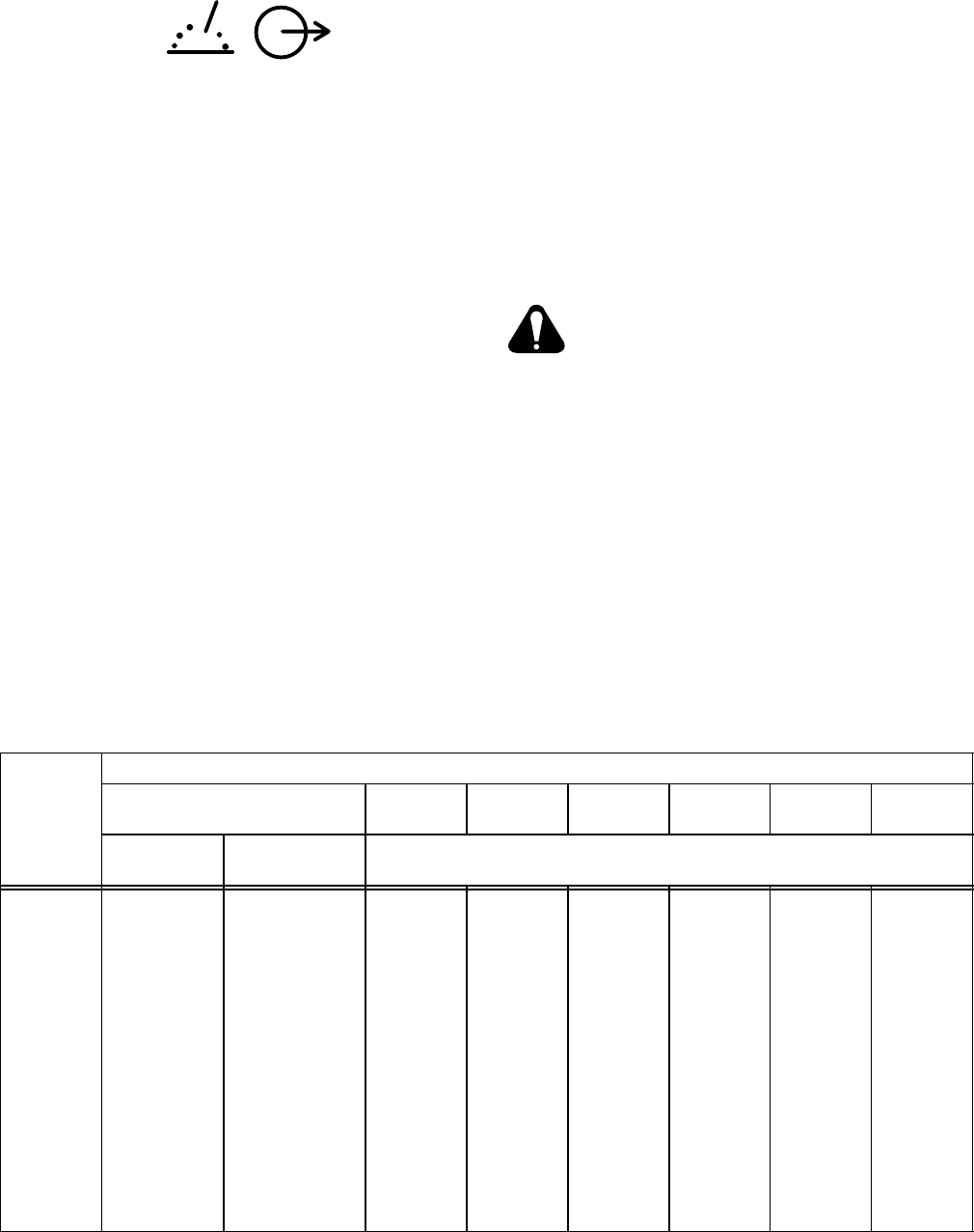
SECTION 3 − SPECIFICATIONS
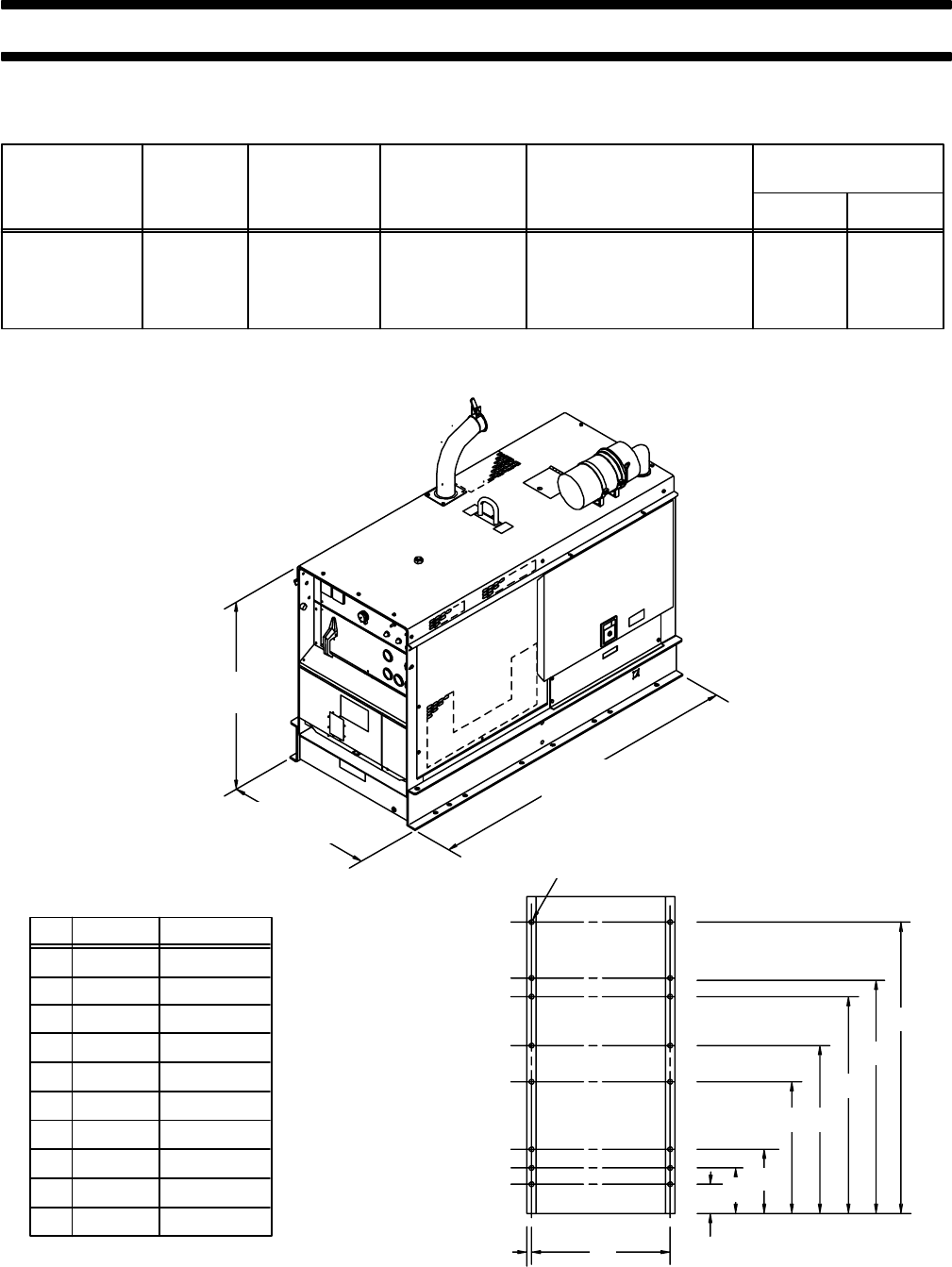
Table 3-1. Welding Generator Specifications
Rated Output
At 100%
Duty Cycle
800 Amperes
At 36 Volts DC
Welding
Range
100 to 800
Amps DC
Maximum
Open-Circuit
Voltage
95 Volts DC
Maximum
Engine Speed
(No Load)
1860 RPM
Single-Phase
Auxiliary Power
While Welding
3 kVA/kW 60 Hz
26 Amperes At 120 Volts
Weight
Net Ship
2150 lbs.
(975 kg) 2280 lbs.
(1034 kg)
80 Volts DC
Nominal
(OCV)
Conforms with NEMA EW1 (ANSI C87.1), “ELECTRIC ARC WELDING POWER SOURCES,” Class I (100).
A
B
C
D
E
F
G
H
J
Inches
62-3/8
50-1/2
46-1/2
36
28-3/16
13-3/4
9-3/4
6-1/8
29-7/8
Millimeters
1584
1283
1181
914
716
349
248
156
759
K1-1/16 27
A
B
C
DE
F
G
H
JK ST-147 323-B
21/32 in. (16.7 mm)
Dia. All Holes
47 in.
(1194 mm)
32 in.
(813 mm)
72 in.
(1829 mm)
Figure 3-1. Overall Dimensions And Mounting Hole Locations
OM-166 941 Page 8
3-1. DUTY CYCLE
The duty cycle of a welding generator is the percentage
of a ten minute period that a welding generator can be
operated at a given output without causing overheating
and damage to the unit. This welding generator is rated
at 100 percent duty cycle when operated at 800 am-
peres. This means that the welding generator can be op-
erated at 800 amperes continuously without causing
damage to the unit.
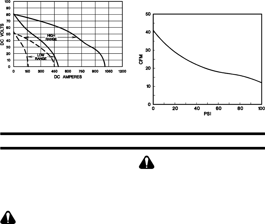
3-2. VOLT-AMPERE CURVES (Chart 3-1)
The volt-ampere curves show the voltage and amper-
age output capabilities of the welding generator at mini-
mum and maximum of each coarse range. Curves of
other settings fall between the curves shown.
Chart 3-1. Volt-Ampere Curves
SB-168 387
3-3. DESCRIPTION
This unit is a constant current (CC) dc arc welding gen-
erator designed for use with the Shielded Metal Arc
Welding (SMAW), Flux Cored Arc Welding (FCAW),
and Air Carbon Arc Cutting And Gouging (CAC-A) pro-
cesses.
The unit is equipped with a four-cylinder, air-cooled,
Deutz diesel engine (F4L-912). The air compressor in
this unit is mounted on the front of the engine, and it op-
erates whenever the engine is running. The compressor
delivers 12 cfm of air at a pressure of 100 psi (see Chart
3-2).
In addition to welding and air compressor operation, this
unit can provide up to 3 kVA/kW of 120 volts (26 am-
peres) ac electrical power for operating 50/60 Hz or 60
Hz auxiliary equipment while welding.
This unit is specially prepared for operation in harsh and
corrosive environments.
An optional Ether Starting Aid can be provided on the
welding generator and is covered within this Owner’s
Manual.
Chart 3-2. Air Output Curve
SB-143 883
SECTION 4 − INSTALLATION OR RELOCATION
IMPORTANT: Unless otherwise specified, all direc-
tions, such as left or right, are with respect to the opera-
tor facing the welding generator front panel.
4-1. LOCATION (Figure 3-1)
A proper installation site should be selected for the weld-
ing generator if the unit is to provide dependable service
and remain relatively maintenance free.
WARNING: ENGINE EXHAUST GASES can
kill.
•Operate in open, well-ventilated areas or if
operated indoors, vent engine exhaust out-
side the building.
•Keep engine exhaust vent outlet away from
building air intakes.
CAUTION: RESTRICTED AIRFLOW causes
overheating and possible damage to inter-
nal parts.
•Maintain at least 18 inches (457 mm) of unre-
stricted space on all sides of unit, and keep
underside free of obstructions.
•Do not place any filtering device over the
intake air passages of this welding generator.
Warranty is void if any type of filtering device is
used.
The service life and operating efficiency of this
unit are reduced when the unit is subjected to
extreme levels of dust, dirt, moisture, corrosive
vapors, and extreme heat.
OM-166 941 Page 9
A. Lifting Of Equipment
WARNING: INCORRECT LIFTING will dam-
age internal parts; FALLING EQUIPMENT
can cause serious personal injury and
equipment damage.
•Use lifting eye to lift unit only, NOT gas cylin-
ders, trailer, or any other heavy options, ac-
cessories, or devices.
•Use equipment of adequate capacity to lift the
unit.
•Use lift forks at least 42 in. (1067 mm) long.
•Lift only from engine-end (end opposite front
panel).
B. Trailer Mounting
CAUTION: UNCONTROLLED TILTING OF
TRAILER can result in personal injury or
equipment damage.
•Distribute weight so that trailer tongue weight
is approximately 10% of gross trailer weight.
•Follow trailer manufacturer’s instructions
when mounting welding generator onto
trailer.
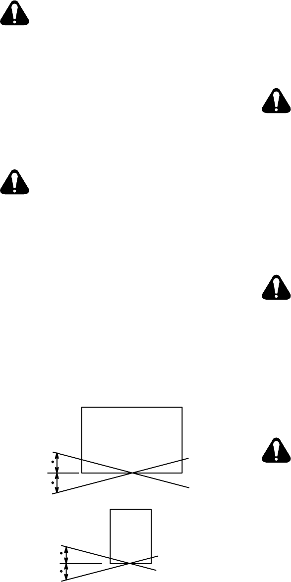
OPERATION ON UNLEVEL SURFACE can
cause improper lubrication and result in
severe engine damage.
•Operate unit in an approximately level posi-
tion.
•See Figure 4-1 for maximum allowable tilt for
proper operation.
•Check crankcase oil level with unit on a level
surface.
Exceeding these limits can cause severe engine
damage and improper operation.
Ref. S-0024
Front
Panel
17.5
15
45
37.5
Side View Of Unit
Front
Panel
End View Of Unit
Figure 4-1. Allowable Tilt Angles For Welding
Generator Engine
Holes are provided in the base for securing the unit in a
permanent location or to a trailer or transport vehicle.
Figure 3-1 gives overall dimensions and base mounting
hole layout.
The mounting location should allow sufficient room to
remove the top cover and side panels for maintenance
and repair functions.
Use a properly fitting cover (optional) over the welding
generator when not in operation to protect the unit from
the environment. Be sure unit is cool before installing
any cover.
C. Spark Arrestor Considerations
WARNING: ENGINE EXHAUST SPARKS can
cause fire.
•Exhaust spark arrestor must be installed in
accordance with local, state, and federal
regulations.
The engine exhaust system on this welding generator is
not equipped with a spark arrestor. A spark arrestor,
maintained in effective working order, is mandatory if
this welding generator is to be operated in a National
Forest or on California Grasslands, brush, or forest cov-
ered land (see Section 4442 of California Public Re-
sources Code). For other areas, check your state and
local laws. If a spark arrestor (optional) is desired, con-
tact your dealer/distributor.
4-2. EXHAUST EXTENSION INSTALLATION
WARNING: HOT ENGINE PARTS can cause
severe burns.
•If applicable, shut down engine and allow ex-
haust system to cool before installing exhaust
extension.
1. Install exhaust extension through top cover
opening, over muffler extension elbow. (Be sure
to face end of extension away from air cleaner;
see Figure 3-1).
2. Secure exhaust extension to top cover of unit us-
ing supplied hardware.
4-3. CONNECTING THE BATTERY
WARNING: BATTERY ACID can burn eyes
and skin and destroy clothing and other ma-
terial.
•Wear a face shield and proper protective
clothing when working with batteries.
ABNORMAL VOLTAGE can cause damage
to engine electrical components.
•Do not operate engine without the battery
connected.
•Do not disconnect the battery while the en-
gine is running.
IMPORTANT: Be sure the Engine Control switch is in
the OFF position before connecting battery.
This unit is equipped with a maintenance-free battery.
To place the unit in service, remove the left, rear side
panel, connect the negative (−) battery cable to the neg-
ative battery terminal, and reinstall the side panel. No
other preparation should be required. If the battery does
not supply enough power to crank the engine, charge
the battery according to Section 8-6.

OM-166 941 Page 10
4-4. FUEL
WARNING: REMOVE FUEL CAP SLOWLY;
FUEL SPRAY may cause injury; FUEL may
be under pressure.
•Rotate fuel cap slowly and wait until hissing
stops before removing cap.
ENGINE FUEL can cause fire or explosion.
•Stop engine before checking or adding fuel.
•Do not spill fuel; if spilled, wipe up.
•Do not refuel if engine is hot or running.
•Do not refuel near sparks or open flame.
•Do not smoke while refueling.
•Do not fill fuel tank to top; allow 1/2 in. (13
mm) from fuel to tank top for expansion.
•Do not weld on fuel tank.
IMPORTANT: Fill fuel tank up to 1/2 in. (13 mm) from
top with fresh fuel before starting engine the first time.
Rust and corrosion preventative was added to inside of
fuel tank and engine at the factory and could cause
rough engine running if not properly diluted with a full
tank of fresh fuel.
The capacity of the fuel tank is 30 gallons U.S. Measure
(114 liters). See the Engine Manufacturer’s Manual for
fuel recommendations. Chart 4-1 illustrates typical fuel
consumption under specific load conditions. Fuel con-
sumption varies from one engine to another. Different
brands of fuel, operating conditions, condition of the en-
gine, etc., also affect the fuel consumption level.
Keep the fuel tank filled to ensure that the injector sys-
tem receives an adequate supply of fuel. The fuel cap is
located on the lower front panel, behind the right access
door (see Figure 4-2). If the fuel tank is allowed to empty,
air will enter the system, causing starting problems. The
Engine Manufacturer’s Manual outlines procedures for
air bleeding the fuel system.
4-5. LUBRICATION (Figure 4-2)
A. Oil And Oil Level Indicator
The engine is shipped with its crankcase filled with SAE
20 break-in oil. An oil level indicator is provided on the
lower front panel of this unit (see Figure 4-2). If oil level is
below the lower pointer when engine is running, add oil
according to the recommendations in the Engine Man-
ufacturer’s Manual (F4L-912 engine). The oil cap is lo-
cated under the access door on the top cover.
IMPORTANT: This engine is equipped with an Oil Pres-
sure Shutdown gauge/switch and an Oil Temperature
Shutdown gauge/switch. If oil pressure becomes too
low or oil temperature rises to a level that may cause en-
gine damage, the respective gauge/switch shuts down
the engine. The shutdown oil pressure has been factory
set at 30 psi (207 kPa), and the shutdown oil tempera-
ture has been set at 265°F (130°C).
B. Wetstacking Considerations
Wetstacking is an accumulation of unburned fuel and oil
in the exhaust pipe. The engine may use oil and wet-
stacking may occur during the run-in period if the piston
rings are not seated properly. If oil consumption and
wetstacking occur during run-in period, see Section
8-12.
4-6. EQUIPMENT GROUNDING TERMINAL
GROUND
This unit is equipped with a grounding terminal for
grounding the generator case. The grounding terminal
is located on the lower front panel (see Figure 4-2).
Since the generator neutral is connected to the frame,
the equipment grounding terminal must be connected to
a proper earth ground. Additionally, comply with all na-
tional, regional, and local codes concerning portable
generators for the specific application.
For detailed grounding instructions consult your na-
tional, regional, and local codes. If additional informa-
tion regarding your operating circumstances and/or
grounding requirements is needed, consult a qualified
electrician or your dealer. After determining the extent to
which any grounding requirements apply to your par-
ticular situation, follow them explicitly.
Chart 4-1. Fuel Consumption Curve
SB-168 472
OM-166 941 Page 11
4-7. WELD OUTPUT CONNECTIONS (Table 4-1
And Figure 4-2)
RATED WELD OUTPUT
To obtain full rated output from this unit, it is necessary to
select, prepare, and install proper weld cables. Failure
to comply in any of these areas may result in
unsatisfactory welding performance.
A. Weld Cable Selection
Use the following guidelines to select weld cables:
1. Use the shortest possible cables, and place
cables close together. Excessive cable lengths
may reduce output or cause unit overload due to
added resistance.
2. Use weld cable with an insulation voltage rating
equal to or greater than the maximum open-cir-
cuit voltage (ocv) of the welding generator (see
Table 3-1 for unit maximum ocv rating).
3. Select weld cable size according to maximum
weld output and total length of connecting cables
in weld circuit. For example, if a 25 foot (7.5 m)
wire feeder or electrode holder cable is used with
a 25 foot (7.5 m) work cable, select the cable size
recommended in Table 4-1 for 50 feet (15 m).
4. Do not use damaged or frayed cables.
B. Weld Cable Preparation
1. Install electrode holder to cable following man-
ufacturer’s instructions. Always use an insulated
electrode holder to ensure operator safety.
2. Install correct size lugs onto ends of both cables
for connecting to work clamp, electrode holder or
wire feeder, and weld output terminals.
3. Install work clamp onto cable.
C. Weld Output Connections
POSITIVE NEGATIVE
+−
WARNING: ELECTRIC SHOCK can kill.
•Do not touch live electrical parts.
•Stop engine, and disconnect negative (−) bat-
tery cable before making any weld output
connections.
MOVING PARTS can cause serious injury.
•Keep away from moving parts such as fans,
belts, and rotors.
1. Open and secure the lower front panel access
door, and route weld cables through bracket on
front upright to the weld output terminals (see
Figure 4-2).
Table 4-1. Weld Cable Size*
Total Cable (Copper) Length In Weld Circuit Not Exceeding
100 ft (30 m) Or Less 150 ft
(45 m) 200 ft
(60 m) 250 ft
(70 m) 300 ft
(90 m) 350 ft
(105 m) 400 ft
(120 m)
Welding
Amperes 10 To 60%
Duty Cycle 60 Thru 100%
Duty Cycle 10 Thru 100% Duty Cycle
100 4 4 4 3 2 1 1/0 1/0
150 3 3 2 1 1/0 2/0 3/0 3/0
200 3 2 1 1/0 2/0 3/0 4/0 4/0
250 2 1 1/0 2/0 3/0 4/0 2-2/0 2-2/0
300 1 1/0 2/0 3/0 4/0 2-2/0 2-3/0 2-3/0
350 1/0 2/0 3/0 4/0 2-2/0 2-3/0 2-3/0 2-4/0
400 1/0 2/0 3/0 4/0 2-2/0 2-3/0 2-4/0 2-4/0
500 2/0 3/0 4/0 2-2/0 2-3/0 2-4/0 3-3/0 3-3/0
600 3/0 4/0 2-2/0 2-3/0 2-4/0 3-3/0 3-4/0 3-4/0
700 4/0 2-2/0 2-3/0 2-4/0 3-3/0 3-4/0 3-4/0 4-4/0
800 4/0 2-2/0 2-3/0 2-4/0 3-4/0 3-4/0 4-4/0 4-4/0
900 2-2/0 2-3/0 2-4/0 3-3/0 3-4/0 4-4/0 4-4/0
*Weld cable size (AWG) is based on either a 4 volts or less drop or a current density of at least 300 circular mils per ampere. S-0007-D
OM-166 941 Page 12
2. For Shielded Metal Arc Welding (SMAW) and Air
Carbon Arc Cutting and Gouging (CAC-A) (Elec-
trode Positive/Reverse Polarity), connect weld
cables as follows:
a. Connect one end of work cable to NEGATIVE
(−) weld output terminal.
b. Connect end of electrode holder cable to POSI-
TIVE (+) weld output terminal.
IMPORTANT: For Electrode Negative/Straight Polarity
connections, reverse cable connections to weld output
terminals; electrode becomes negative.
3. For Wire Feeding Processes (GMAW, FCAW,
SAW) (Electrode Positive/Reverse Polarity),
connect weld cables as follows:
a. Connect one end of work cable to NEGATIVE
(−) weld output terminal.
b. Connect end of electrode holder cable to POSI-
TIVE (+) weld output terminal and remaining
end to terminal on the wire feeder drive housing
(see wire feeder Owner’s Manual for location).
4. Close and secure front panel access door.
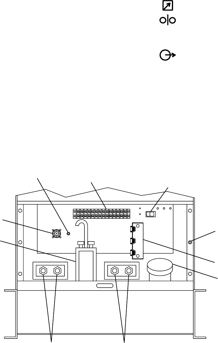
4-8. REMOTE CONTROL CONNECTIONS
A. Remote 9 Receptacle Information And
Connections (Figures 4-2 And 4-3)
REMOTE 9
FEEDER
AMPERAGE/
A/V
OUTPUT
(CONTACTOR)
VOLTAGE
REMOTE 9 receptacle RC3, located under the lower
front panel access door (see Figure 4-2), is provided to
connect any of the following equipment to the welding
generator circuitry:
a. Remote Contactor
b. Remote Amperage or Voltage control
c. Wire feeder which provides contactor control to
the welding generator.
d. Combination of the above.
To Make connections, align keyway, insert plug, and ro-
tate threaded collar fully clockwise.
POSITIVE (+)
Weld Output NEGATIVE (−)
Weld Output
Circuit Breaker CB1
(see Section 9-3)
Equipment
Grounding
Terminal
Terminal
Fuel Cap
Remote 9
Strain Relief
Ref. ST-147 322-E
Strip 3T
Circuit Breaker CB3
Receptacle
Terminals Terminals
Oil Level
Indicator
Figure 4-2. Lower Front Panel Components And Connections

OM-166 941 Page 13
If supplied remote control cord is not suitable for con-
necting to the REMOTE 9 receptacle RC3, proceed with
one of the following alternatives;
1. Wire a plug or cord to interface with REMOTE 9
receptacle RC3 using socket information in Sec-
tion C.
2. Wire remote control cord directly to terminal strip
within unit according to Section B.
B. REMOTE Terminal Strip 3T Information And
Connections (Figures 4-2 And 4-4)
WARNING: ELECTRIC SHOCK can kill; UN-
EXPECTED OUTPUT can cause serious in-
jury.
•Do not touch live electrical parts.
•Stop engine, and disconnect negative (−)
battery cable from battery before making any
internal inspection or connections.
•Do not connect to REMOTE 9 receptacle and
terminal strip at the same time.
Since the OUTPUT (CONTACTOR) can be en-
ergized from either the receptacle or terminal
strip, it is vital to use only one remote control
method.
MOVING PARTS can cause serious injury.
•Keep away from moving parts such as fans,
belts, and rotors.
Terminal strip 3T, mounted on the lower front panel (see
Figure 4-2), is included in case the plug supplied on the
remote control cord is not suitable for connections to the
REMOTE 9 receptacle RC3.
To make connections, proceed as follows:
1. Remove existing plug from remote control cord.
2. Open and secure lower front door.
3. Locate strain reliefs provided on lower front panel
(see Figure 4-2).
4. Insert leads from cord through strain relief.
5. For Remote Electrical Cutoff Switch, remove
jumper link between terminals N and P.
6. Connect leads to terminal strip 3T using terminal
information provided in Section C.
7. Secure the cord in the strain relief.
8. Close and secure door.
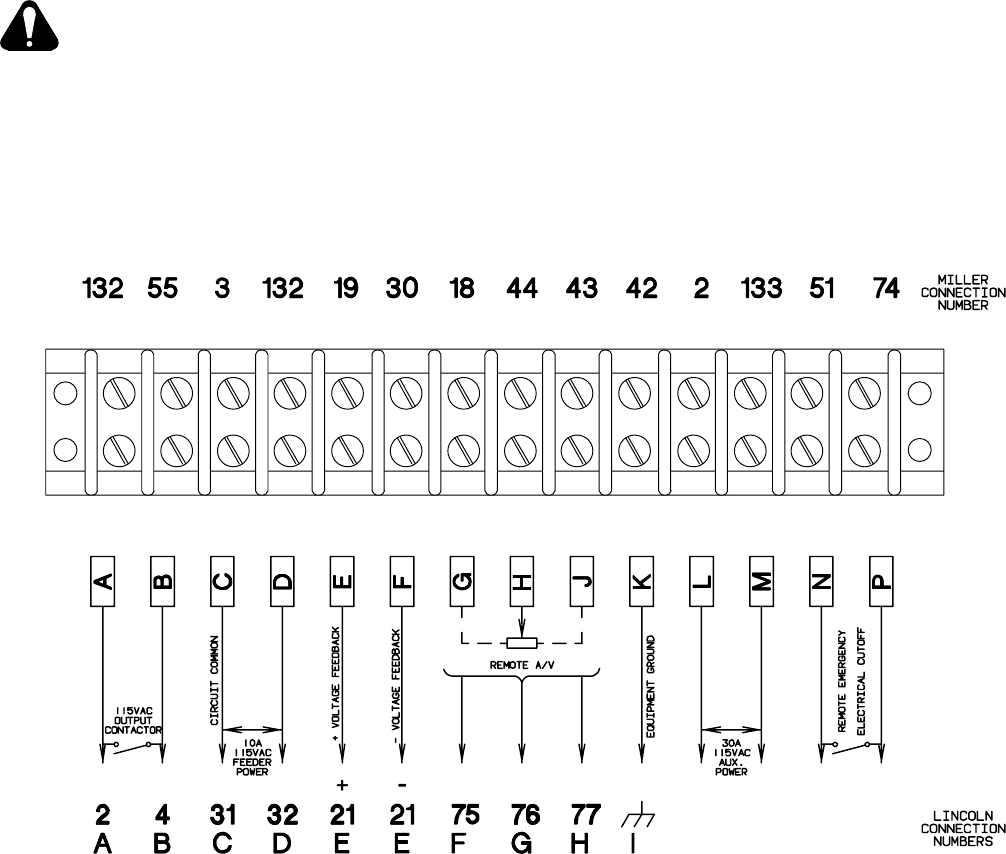
C. Socket/Terminal Information (Figure 4-4)
The following lists the functions of the sockets of RE-
MOTE 9 receptacle RC3 (see Figure 4-3), and the termi-
nals of strip 3T (see Figure 4-4). The following socket/
terminal information is provided in case it is necessary to
wire the auxiliary equipment cord.
AB
C
D
E
F
G
H
I
Ref. S-0706
Figure 4-3. Front View Of Remote 9 Receptacle
With Socket Locations
Socket A/Terminal A:
Contact closure to Socket B/Terminal B
completes the 115 volts ac contactor con-
trol circuit; protected by circuit breaker
CB3.
Socket B/Terminal B:
Contactor closure to Socket A/Terminal A
completes the 115 volts ac contactor con-
trol circuit.
Socket H/Terminal J:
Command reference; +10 volts dc.
Socket F/Terminal G:
Control circuit common.
Socket G/Terminal H:
Input command signal from wiper of re-
mote control potentiometer; 0 volts equals
machine minimum; +10 volts equals ma-
chine maximum.
Socket C/Terminal C:
115 volts ac circuit common; also con-
nected to welding power source chassis.
Socket D/Terminal D:
Up to 10 amperes of 115 volts ac, 60 Hz,
with respect to terminal C (circuit
common).
Terminals L and M of 3T:
Terminals supply 30 amperes of 115 volts
ac, 60 Hz, auxiliary power. Terminal L is
circuit common.
Terminals E/Terminal E or F:
Weld Voltage Feedback. Polarity
determined by connection at terminal E (+)
or F (−).
Terminal N and P of 3T:
Closed circuit between terminals N and P
is normal condition. Open circuit between
terminals N and P is Remote Emergency
Electrical Cutoff condition.
Terminal I/Terminal K:
Machine chassis (Equipment Ground).
OM-166 941 Page 14
4-9. AIR COMPRESSOR CONNECTIONS
This unit delivers 12 cfm of air at a pressure of 100 psi
whenever the engine is running. A 1/2 in. NPT fitting for
air compressor connections is provided on the top cover
of the unit.
To make connections to the air compressor, obtain and
install a quick-connect connector onto the air compres-
sor fitting.
4-10. ETHER STARTING AID (Optional)
This unit is shipped without the ether cylinder. Before
this device is operational, an ether cylinder must be ob-
tained and installed. To install the ether cylinder, pro-
ceed as follows:
WARNING: IMPROPER HANDLING OR EX-
POSURE TO ETHER can seriously harm
your health.
•Follow the manufacturer’s safety instructions
on the cylinder when handling ether compo-
nents.
IMPORTANT: Before installing the ether cylinder, clean
nozzle on ether cylinder and fitting into which the ether
cylinder is inserted. If dirt is present in either of these ar-
eas, the system may not work.
1. Open and secure right rear side door.
2. If applicable, remove protective cap from ether
valve, or remove old ether cylinder from unit.
3. Loosen cylinder clamp, install ether cylinder, and
tighten clamp.
IMPORTANT: After installing or replacing ether cylin-
der, do not use or test ether start system for at least 10 to
15 minutes to allow particles in fuel to settle to prevent
atomizer plugging.
4. Using a liquid soap and water solution, check all
ether start system connections for leaks. If a leak
exists, escaping gas will produce bubbles in the
solution.
5. Close and secure side door.
Ref. ST-164 613-A
Figure 4-4. Terminal Strip 3T Information
OM-166 941 Page 15
SECTION 5 − AUXILIARY POWER
POWER OUTPUT
WARNING: ELECTRIC SHOCK can kill;
MOVING PARTS can cause serious injury;
IMPROPER AIR FLOW AND EXPOSURE TO
ENVIRONMENT can damage internal parts.
•Do not touch live electrical parts.
•Stop the engine and disconnect negative (−)
battery cable from battery before making in-
ternal inspection or reconnection.
•Ground generator as required by any applica-
ble national, state, and local electrical codes.
The generator neutral is connected to the frame;
therefore, the equipment grounding terminal
must be connected to a proper earth ground.
•Do not connect to any electrical distribution
system normally supplied by utility power un-
less a proper transfer switch and grounding
procedure are employed.
•Keep away from moving parts such as fans,
belts, and rotors.
•Keep all covers and panels in place while op-
erating.
Warranty is void if unit is operated with any por-
tion of the outer enclosure removed.
ELECTRIC SPARKS can cause fire.
•Disconnect weld cables when using auxiliary
power.
The weld output terminals are electrically ener-
gized when the engine is running and the con-
tactor (if applicable) is energized.
•Watch for fire.
•Have a fire extinguisher nearby, and know
how to use it.
LOW VOLTAGE AND FREQUENCY can dam-
age electrical equipment.
•Turn off or unplug all electrical equipment
connected to auxiliary power before starting
or stopping the engine.
When starting or stopping, the engine has low
speed which causes low voltage and frequency.
5-1. GENERAL
Calculate load requirements before connecting equip-
ment to the auxiliary power terminals on terminal strip
3T. For best performance (voltage and frequency regu-
lation), limit connected load to approximately 90% of
generator capability.
A brief period (less than 5 seconds) of large current draw
is required for starting motor-driven equipment. This
generator can supply 25% of rated current output at the
terminal strip for motor starting. Disconnect motor from
generator before starting engine. Use adequate size
cords so that voltage drop at the motor is not excessive.
Voltage drops significantly when starting motor-driven
equipment.
Ground fault circuit interrupters (GFCI) may be re-
quired. Check local and state codes, and the latest issue
of the National Electrical Code.
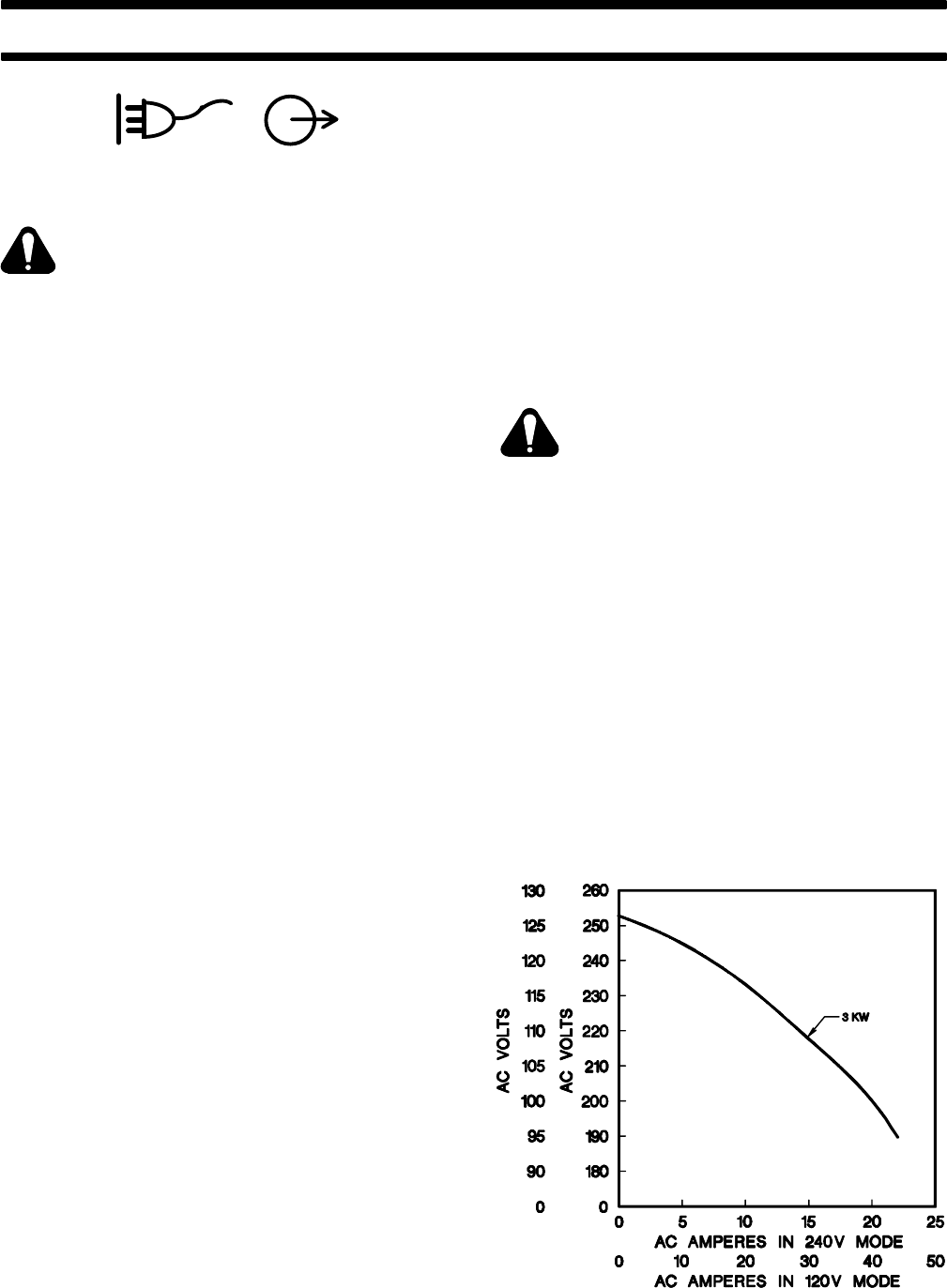
5-2. 120 VOLT TERMINALS (Chart 5-1, And
Figure 4-2)
WARNING: ELECTRIC SHOCK can kill.
•Do not touch live electrical parts.
•Stop engine, and disconnect negative (
−)
battery cable from battery before beginni
ng
this installation.
MOVING PARTS can cause serious injur
y.
•Keep away from moving parts such as fan
s,
belts, and rotors.
HOT SURFACES can cause severe burn
s.
•Wear protective gloves and clothing wh
en
working near a hot engine.
•Allow components to cool completely b
e-
fore touching.
IMPORTANT: All directions, such as left or right, are
with respect to the operator facing the welding generator
front panel. Retain all hardware removed during this
procedure for reinstallation unless specifically told
otherwise.
Chart 5-1. AC Power Curve For 120 Volt Terminals
SB-109 365-B
OM-166 941 Page 16
A. Auxiliary Equipment Connections To Terminal
Strip 3T (Figure 4-2)
WARNING: Read and follow safety infor-
mation at beginning of entire Section 5-2
before proceeding.
Terminal strip 3T is provided to directly wire the auxiliary
power cord(s) into the unit. To make connections, pro-
ceed as follows:
1. Remove plug from auxiliary equipment cord(s), if
applicable.
2. Open and secure lower front door.
3. Locate three strain reliefs on lower front panel.
4. Insert leads from cord(s) through a strain relief.
5. Connect leads to terminal strip 3T using terminal
information provided in Figure 4-4.
6. Secure the cord(s) in the strain relief(s).
7. Close and secure door.
B. Protection
Circuit breaker CB1 protects the 120 volts ac auxiliary
power terminals from overload. See Section 9-3 for CB1
location and resetting procedure.
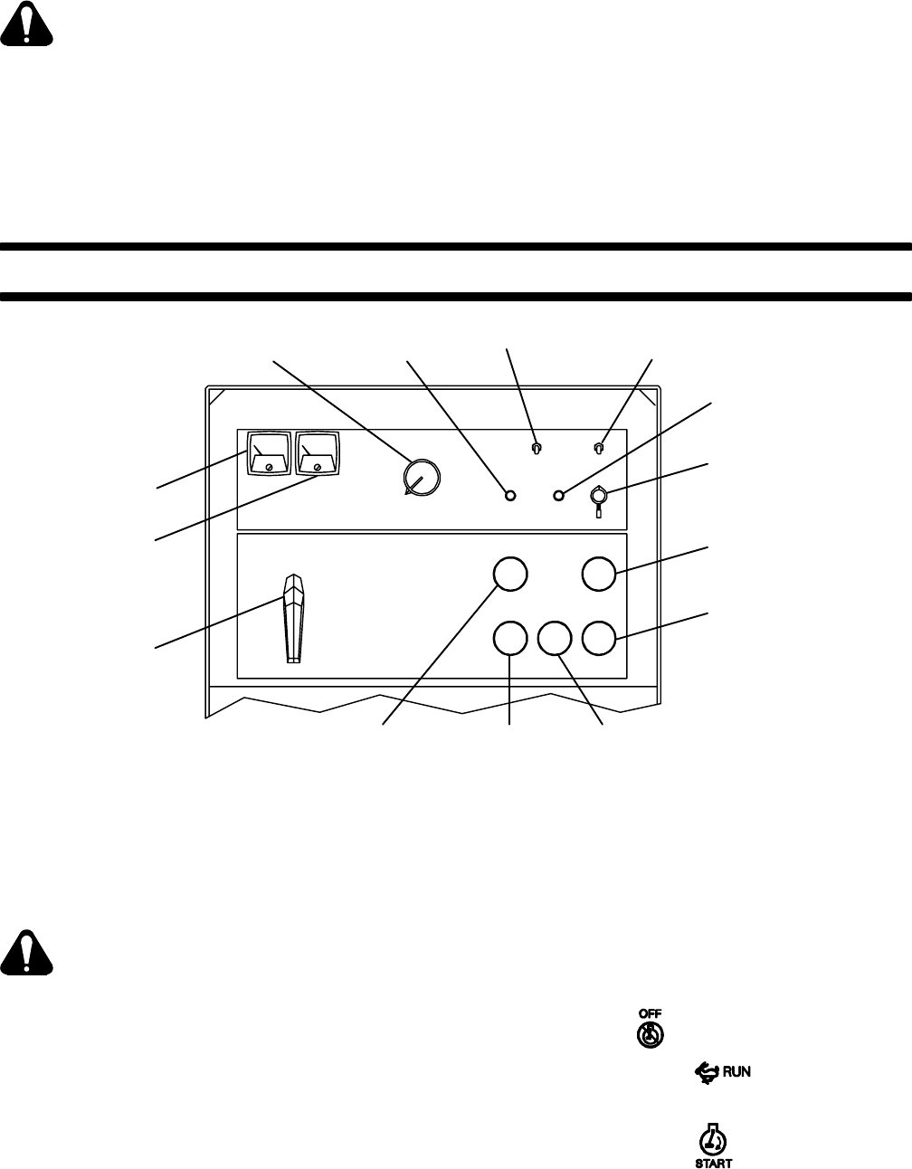
SECTION 6 − OPERATOR CONTROLS
Engine Hours
Meter Oil Temperature
Gauge/Switch Oil Pressure
Gauge/Switch
Battery Ampere
Gauge
Fuel Gauge
Engine Control
Switch
Check Alternator
Light
Output
(Contactor)
Switch
Ammeter
Voltmeter
Remote Amperage &
Voltage Switch
Service Engine
Air Cleaner
Light
Amperage &
Voltage Adjustment
Control
Ref. ST-147 322-E
Ampere
Ranges
Switch
Figure 8-1. Operator Controls
6-1. AMPERE RANGES SWITCH (Figure 6-1)
The Ampere Ranges switch provides two coarse am-
perage ranges. When in LOW OUTPUT, amperage
range is 100-350 amperes. When in HIGH OUTPUT,
amperage range is 300-800 amperes.
CAUTION: ARCING can damage switch
contacts.
•Do not change the position of the Ampere
Ranges switch while welding or under load.
Arcing causes the contacts to become pitted
and eventually inoperative.
6-2. AMPERAGE & VOLTAGE ADJUSTMENT
CONTROL (Figure 6-1)
A/V
AMPERAGE AND VOLTAGE
ADJUSTMENT
The AMPERAGE & VOLTAGE ADJUSTMENT control
adjusts welding amperage within range selected by Am-
pere Ranges switch.The scale surrounding the control
is calibrated in percent and does not indicate an actual
amperage or voltage value.
IMPORTANT: The AMPERAGE & VOLTAGE AD-
JUSTMENT control may be adjusted while welding.
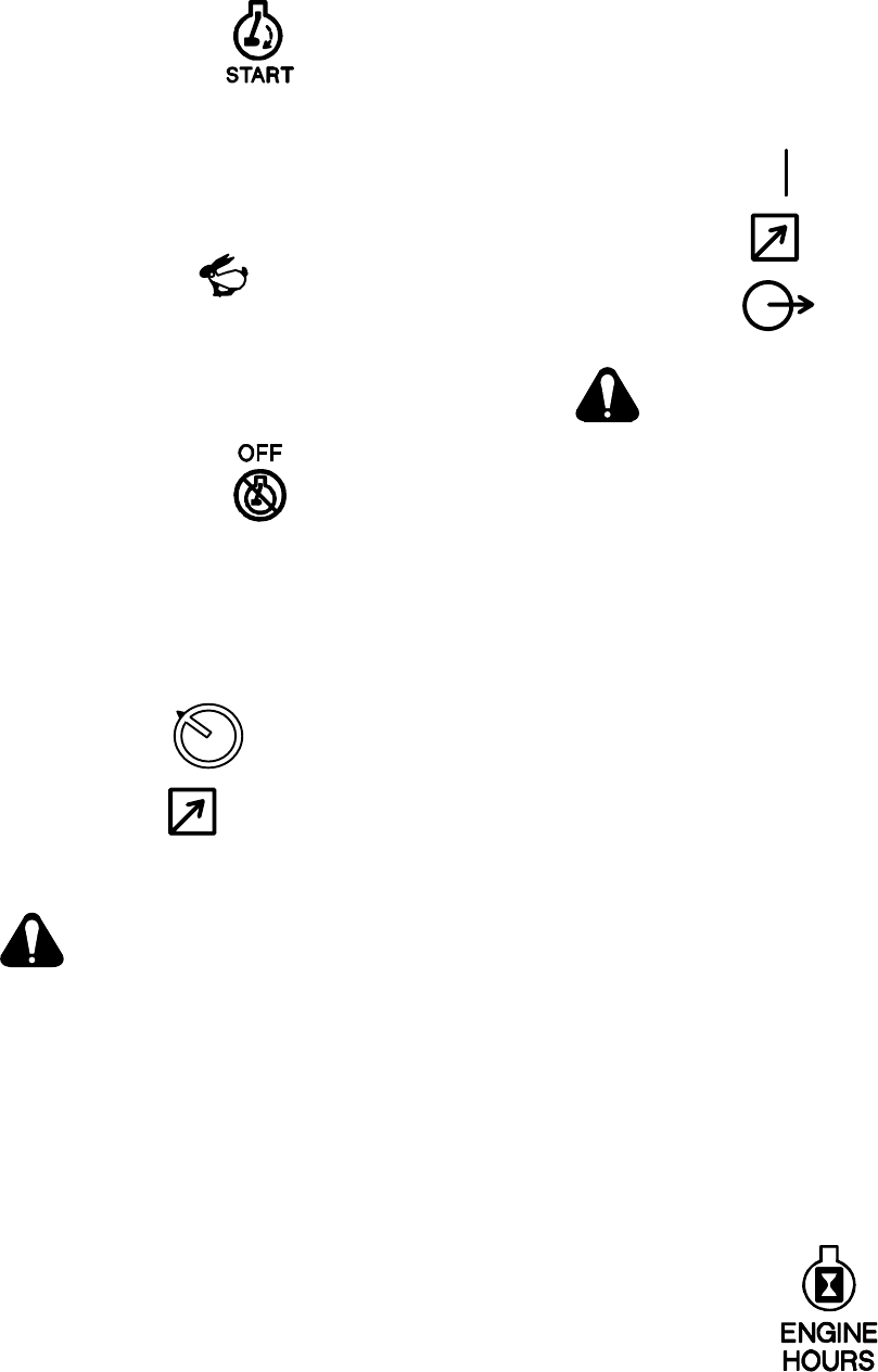
6-3. ENGINE CONTROL SWITCH (Figure 6-1)
The Engine Control switch has three positions: START,
RUN, and OFF.
OM-166 941 Page 17
A. START Position
Rotating the switch to the START position starts the en-
gine. Release the switch as soon as the engine starts,
and the switch automatically returns to the RUN posi-
tion.
B. RUN Position
RUN
When the Engine Control switch is in the RUN position,
engine speed remains at governed weld/power speed
(1860 rpm).
C. OFF Position
Rotating the Engine Control switch to the OFF position
disconnects battery voltage, thereby shutting down the
engine.
6-4. REMOTE AMPERAGE & VOLTAGE CON-
TROL SWITCH (Figure 6-1)
A/V
REMOTE
PANEL
WARNING: ELECTRIC SHOCK can kill.
•Do not touch live electrical parts.
•Do not touch the output terminals when the
contactor is energized
•Do not touch welding wire or electrode and
work clamp at same time.
If remote amperage or voltage control is desired, make
connections to the REMOTE 9 receptacle terminal strip
according to Section 4-8, and place the AMPERAGE &
VOLTAGE switch in the REMOTE position. When a Re-
mote Amperage or Voltage Control is being used, the re-
mote control functions as a fine amperage or voltage ad-
justment for the AMPERAGE & VOLTAGE ADJUST-
MENT control on the welding generator. For example, if
the AMPERAGE & VOLTAGE ADJUSTMENT control
on the welding generator is set at midrange, the Remote
Amperage or Voltage Control will provide (from mini-
mum to maximum adjustment) fine amperage or voltage
adjustment of one half of the welding generator output
for the range selected. For complete remote control of
the output, rotate the AMPERAGE & VOLTAGE AD-
JUSTMENT control to the maximum position.
If remote amperage or voltage is not desired, place the
AMPERAGE & VOLTAGE switch in the PANEL posi-
tion. Only the AMPERAGE & VOLTAGE ADJUST-
MENT control will adjust output.
6-5. OUTPUT(CONTACTOR) SWITCH (Figure
6-1)
REMOTE
OUTPUT
(CONTACTOR)
ON
WARNING: ELECTRIC SHOCK can kill.
•Do not touch live electrical parts.
•Do not touch the output terminals when the
contactor is energized.
•Do not touch welding wire or electrode and
work clamp at same time.
When the OUTPUT/CONTACTOR switch is in
the ON position, open-circuit voltage is present
at the weld output terminals for as long as the
engine is running.
If the OUTPUT(CONTACTOR) switch is in the ON posi-
tion, open-circuit voltage will be present at the output
terminals whenever the engine is running.
If remote contactor control by means of a wire feeder or
remote device is desired, make connections to the RE-
MOTE 9 receptacle or terminal strip 3T according to
Section 4-8, and place the OUTPUT(CONTACTOR)
switch in the REMOTE position. Open-circuit voltage is
present at the weld output terminals whenever the gun
switch or remote device is closed.
6-6. SERVICE ENGINE AIR CLEANER LIGHT
(Figure 6-1)
This unit is equipped with an engine air cleaner. When
the SERVICE ENGINE AIR CLEANER light PL1 comes
on, the air cleaner requires servicing (see Section 8-2).
6-7. CHECK ALTERNATOR (Figure 6-1)
The CHECK ALTERNATOR light PL3 comes on if the al-
ternator requires servicing. If the light comes on, check
for loose or broken engine belt.
6-8. HOUR METER (Figure 6-1)
This unit is equipped with an hour meter. The meter, la-
beled ENGINE HOURS, registers the total hours of en-
gine operation. This information is useful for routine
maintenance on the engine.
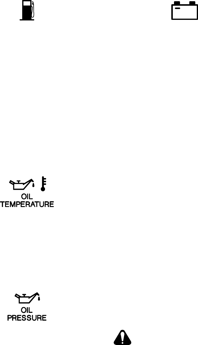
OM-166 941 Page 18
6-9. FUEL GAUGE (Figure 6-1)
FUEL
The FUEL Gauge indicates the level of fuel remaining in
the fuel tank. The unit is equipped with a 30 gallon (114
L) fuel tank.
6-10. MAGNETIC SHUTDOWN SWITCH
An internal switch automatically shuts down the engine
if oil pressure drops to an unsafe level or oil temperature
becomes too high.
The switch assembly is located directly behind the up-
per front panel access door, in the upper left corner. The
switch is protected by a fuse located on the bottom of the
switch assembly. Should this fuse open, the engine
would not start. See Section 9-3 for fuse replacement
procedure.
6-11. OIL TEMPERATURE GAUGE/SWITCH (Fig-
ure 6-1)
The OIL TEMPERATURE gauge/switch registers the
temperature of the oil in the lubricating system. If the oil
temperature rises to a level that may cause engine dam-
age (factory set at 265°F, 130°C), switch closes and
magnetic shutdown switch stops the engine (see Sec-
tion 6-10).
6-12. OIL PRESSURE GAUGE/SWITCH (Figure
6-1)
The OIL PRESSURE gauge/switch registers the lubri-
cating system pressure in pounds per square inch (psi).
The pressure registered by the gauge should remain
constant for a given engine speed. Should the pressure
fluctuate or drop, stop the engine, and do not operate
until the trouble has been corrected. If the oil pressure
drops to a level that may cause engine damage, switch
closes and magnetic shutdown switch stops the engine
(see Section 6-10). The shutdown oil pressure is factory
set at 30 psi (207 kPa). Normal operating pressure is ap-
proximately 50 psi (345 kPa).
6-13. BATTERY GAUGE (Figure 6-1)
+
BATTERY
The BATTERY voltmeter registers the alternator-
supplied output voltage to the battery. The meter should
always register 12-15 volts dc while the engine is run-
ning. If the voltage is outside this range, stop the engine,
and determine the cause. Do not operate the engine un-
til the trouble has been corrected.
6-14. METERS (Figure 6-1)
The meters are provided to monitor the welding opera-
tion; however, they are not intended for exact amperage
or voltage measurements. These meters are internally
connected to the output circuit.
The voltmeter indicates the voltage at the weld termi-
nals, but not necessarily the actual voltage at the weld-
ing arc (due to cable resistance, poor connections, etc.).
The ammeter indicates the amperage output of the unit.
6-15. BROKEN COOLING BELT SHUTDOWN
SWITCH
An internal switch automatically shuts down the engine
if the cooling belt breaks. The cooling belt is located on
the rear of the engine. If the engine shuts down, check
for broken cooling belt.
6-16. ETHER STARTING AID (Optional)
The cold weather starting components provide a means
of applying a premeasured portion of ether into the man-
ifold. The amount of ether supplied should be sufficient
to permit easy engine starting under cold weather condi-
tions.
Depressing ETHER STARTING AID switch for one sec-
ond while cranking the engine will provide the proper
amount of ether to the manifold. This control will function
only while cranking the engine.
CAUTION: ETHER INJECTION WHILE EN-
GINE IS RUNNING can cause engine dam-
age.
•Do not actuate ETHER STARTING AID while
engine is running.
IMPORTANT: Ether is sprayed into the engine when
this switch is released. Depressing the switch does not
spray the ether into the engine but rather fills the valve
chamber.

OM-166 941 Page 19
SECTION 7 − SEQUENCE OF OPERATION
WARNING: ELECTRIC SHOCK can kill;
MOVING PARTS can cause serious injury;
IMPROPER AIR FLOW AND EXPOSURE TO
ENVIRONMENT can damage internal parts.
•Do not touch live electrical parts.
•Stop the engine and disconnect negative (−)
battery cable from battery before inspecting
or servicing.
•Keep away from moving parts such as fans,
belts, and rotors.
•Keep all covers and panels in place while op-
erating.
Warranty is void if the welding generator is oper-
ated with any portion of the outer enclosure re-
moved.
ARC RAYS can burn eyes and skin; NOISE
can damage hearing.
•Wear correct eye, ear, and body protection.
FUMES AND GASES can seriously harm
your health.
•Ventilate to keep from breathing fumes and
gases.
•If ventilation is inadequate, use approved
breathing device.
•Use in open, well ventilated areas or vent ex-
haust out of doors.
HOT METAL, SPATTER, SLAG, and EX-
HAUST can cause fire and burns.
•Watch for fire.
•Have a fire extinguisher nearby, and know
how to use it.
•Allow work and equipment to cool before han-
dling.
ENGINE FUEL can cause fire or explosion.
•Stop engine before checking or adding fuel.
•Do not spill fuel; if spilled, wipe up.
•Do not refuel if engine is hot or running.
•Do not refuel near sparks or open flame.
•Do not smoke while refueling.
•Do not fill tank to top; allow room for expan-
sion.
MAGNETIC FIELDS FROM HIGH CUR-
RENTS can affect pacemaker operation.
•Wearers should consult with their doctor be-
fore going near arc welding, gouging, or spot
welding operations.
See Section 1-Safety Rules For Operation Of
Arc Welding Power Source for basic welding
safety information.
7-1. SHIELDED METAL ARC WELDING (SMAW)
WARNING: Read and follow safety informa-
tion at beginning of entire Sections 5 and 7
before proceeding.
1. Install and connect unit according to Section 4.
2. Wear dry insulating gloves and clothing.
3. Connect work clamp to clean, bare metal at
workpiece.
4. Select proper electrode.
5. Set Ampere Ranges switch and rotate AMPER-
AGE & VOLTAGE ADJUSTMENT control to the
desired position (see Sections 6-1 and 6-2).
6. If remote amperage control is not used, place
AMPERAGE & VOLTAGE switch in the PANEL
position. If remote amperage control is to be
used, place AMPERAGE & VOLTAGE switch in
the REMOTE position.
7. If remote contactor control is not used, place
OUTPUT(CONTACTOR) switch in the ON posi-
tion. If remote contactor control is to be used,
place OUTPUT(CONTACTOR) switch in the RE-
MOTE position.
8. Start engine as instructed in Section 7-6.
9. Connect desired auxiliary equipment to the 120
volts ac terminals according to Section 5.
10. Place Engine Control switch in the RUN position.
11. Energize auxiliary equipment, if applicable.
12. Wear welding helmet with proper filter lens ac-
cording to ANSI Z49.1.
13. Insert electrode into electrode holder.
14. Begin welding.
7-2. GAS METAL ARC (GMAW) AND FLUX
CORED ARC WELDING (FCAW)
WARNING: Read and follow safety informa-
tion at beginning of entire Sections 5 and 7
before proceeding.
1. Install and connect unit according to Section 4.
2. Install and connect wire feeder to the terminal
strip according to wire feeder Owner’s Manual
and Section 4-8.
3. Wear dry insulating gloves and clothing.
4. Connect work clamp to clean, bare metal at
workpiece.
5. Set Ampere Ranges switch and rotate AMPER-
AGE & VOLTAGE ADJUSTMENT control to the
desired position (see Section 6-1 and 6-2).

OM-166 941 Page 20
6. If remote amperage or voltage control is not
used, place AMPERAGE & VOLTAGE switch in
the PANEL position. If remote amperage or volt-
age control is to be used, place AMPERAGE &
VOLTAGE switch in the REMOTE position.
7. If remote contactor control is not used, place
OUTPUT(CONTACTOR) switch in the ON posi-
tion. If remote contactor control is to be used,
place OUTPUT(CONTACTOR) switch in the RE-
MOTE position.
8. Turn on shielding gas supply, if applicable.
9. Start engine as instructed in Section 7-6.
10. Connect desired auxiliary equipment to the 120
volts ac terminals according to Section 5.
11. Place Engine Control switch in the RUN position.
12. Energize auxiliary equipment, if applicable.
13. Wear welding helmet with proper filter lens ac-
cording to ANSI Z49.1.
14. Begin welding.
7-3. AIR CARBON ARC CUTTING AND GOUGING
(CAC-A) (Table 7-1)
WARNING: Read and follow safety informa-
tion at beginning of entire Sections 5 and 7
before proceeding.
1. Install and connect unit according to Section 4.
2. Wear dry insulating gloves and clothing.
3. Connect work clamp to clean, bare metal at work-
piece.
4. Place AMPERAGE & VOLTAGE switch in the
PANEL position.
5. Place OUTPUT(CONTACTOR) switch in the ON
position.
6. Set Ampere Ranges switch and rotate AMPER-
AGE & VOLTAGE ADJUSTMENT control to the
desired position (see Sections 6-1 and 6-2).
7. Start engine as instructed in Section 7-6.
8. Connect desired auxiliary equipment to the 120
volts ac terminals according to Section 5.
9. Place Engine Control switch in the RUN position.
10. Energize auxiliary equipment, if applicable.
11. Wear welding helmet with proper filter lens ac-
cording to ANSI Z49.1.
12. Begin welding.
Table 7-1. Suggested Electrode Diameter For
Amperage Range (CAC-A Only)
Electrode Diameter Amperage Range
Inches Millimeters Minimum Maximum
1/8 3.2 30 60
5/32 4.0 90 150
3/16 4.8 200 250
1/4 6.4 300 400
5/16 7.9 350 450
3/8 9.5 450 600
1/2 12.7 800 1000
5/8 15.9 1000 1250
3/4 19.0 1250 1600
1 25.4 1600 2200
7-4. AUXILIARY POWER OPERATION
WARNING: Read and follow safety informa-
tion at beginning of entire Sections 5 and 7
before proceeding.
1. Install and connect unit according to Section 4.
2. Install and connect auxiliary power equipment
cord(s) to 120 volts auxiliary power terminals ac-
cording to Section 5-2.
3. Start engine as instructed in Section 7-6.
4. Place Engine Control switch in the RUN position.
5. Energize auxiliary equipment, if applicable. Auxil-
iary power may be obtained whenever engine is
running.
7-5. AIR COMPRESSOR OPERATION (Tables 7-2
And 7-3)
1. Install and connect unit according to Section 4.
2. Install a quick-connect connector onto the air
compressor fitting in top cover of unit.
3. Start engine as instructed in Section 7-6.
4. Begin operation.
7-6. STARTING THE ENGINE
IMPORTANT: Read entire engine Owner’s Manual
(Deutz F4L-912 engine) before operating engine.
1. Engine Prestart Checks
a. Oil Level
Check engine oil level. If oil level is low, fill to top
mark on dipstick (see engine Owner’s Manual
for oil selection specifications and Section 4-5).
If oil consumption and wetstacking occur during
run-in period, see Section 8-12.
OM-166 941 Page 21
b. Fuel Level
WARNING: REMOVE FUEL CAP SLOWLY;
FUEL SPRAY may cause injury; FUEL may
be under pressure.
•Rotate fuel cap slowly and wait until hissing
stops before removing cap.
Check fuel level. If necessary, fill tank with
fresh, clean fuel (see engine Owner’s Manual
for fuel specifications).
c. Cooling System
Check the air cooling system by inspecting the
air intake and exhaust openings for blockage
and blower impeller for obstruction and free
movement. Check the blower/alternator belt for
proper tension (see the engine Owner’s Man-
ual), and ensure that all sheet metal cowlings,
shrouds, and panels are properly in place and
secure.
d. Air Cleaner
Check air cleaner service indicator daily (see
Section 6-6).
2. Rotate Engine Control switch to the START posi-
tion, and if applicable, depress ETHER START-
ING AID switch, if applicable, at the same time —
release ETHER STARTING AID switch after one
second.
CAUTION: REENGAGING STARTER MO-
TOR while flywheel is rotating or EXCEED-
ING RATED CRANKING TIME can damage
starting components.
•Do not reengage starter motor until starter
pinion and flywheel have stopped rotating.
•Do not exceed maximum cranking time of 20
seconds.
Allow two minutes cooling time before attempt-
ing to restart engine.
3. As soon as engine starts, release Engine Control
switch, and allow the engine to warm up for ap-
proximately three minutes with no weld or power
load applied.
7-7. STOPPING THE ENGINE
1. Stop all operations, and turn off or disconnect any
auxiliary equipment.
WARNING: HIGH CONCENTRATION OF
SHIELDING GAS can harm health or kill.
•Shut off gas supply when not in use.
2. Rotate Engine Control switch to the OFF posi-
tion.
Table 7-2. Flow Of Free Air (CFM) Through Orifices Of Various Diameters
Gauge Pressure In
Receiver (lbs.) Orifice Diameter And Free Air Flow (CFM)
1/64” 1/32” 3/64” 1/16” 3/32” 1/8” 3/16” 1/4”
1 0.027 0.107 0.242 0.430 0.97 1.72 3.86 6.85
2 0.038 0.153 0.342 0.607 1.36 2.43 5.42 9.74
3 0.046 0.188 0.471 0.750 1.68 2.98 6.71 11.9
5 0.059 0.242 0.545 0.965 2.18 3.86 8.71 15.4
10 0.084 0.342 0.77 1.36 3.08 5.45 12.3 21.8
15 0.103 0.418 0.94 1.67 3.75 6.65 15.0 26.7
20 0.119 0.485 1.07 1.93 4.25 7.7 17.1 30.8
25 0.133 0.54 1.21 2.16 4.75 8.6 19.4 34.5
30 0.156 0.632 1.40 2.52 5.6 10.0 22.5 40.0
35 0.173 0.71 1.56 2.80 6.2 11.2 25.0 44.7
40 0.19 0.77 1.71 3.07 6.8 12.3 27.3 49.1
45 0.208 0.843 1.9 3.36 7.6 13.4 30.3 53.8
50 0.225 9.14 2.05 3.64 8.2 14.5 32.8 58.2
60 0.26 1.05 2.35 4.2 9.4 16.8 37.5 67.0
70 0.295 1.19 2.68 4.76 10.7 19.0 43.0 76.0
80 0.33 1.33 2.97 5.32 11.9 21.2 47.5 85.0
90 0.364 1.47 3.28 5.87 13.1 23.5 52.5 94.0
100 0.40 1.61 3.66 6.45 14.5 25.8 58.3 103.0
110 0.43 1.76 3.95 7.00 15.7 28.0 63.0 112.0
120 0.47 1.90 4.27 7.58 17.0 30.2 68.0 121.0
130 0.50 2.04 4.57 8.13 18.2 32.4 73.0 130.0
140 0.54 2.17 4.87 8.68 19.5 34.5 78.0 138.0
150 0.57 2.33 5.2 9.20 20.7 36.7 83.0 147.0
175 0.66 2.65 5.94 10.6 23.8 42.1 95.0 169.0
200 0.76 3.07 6.90 12.2 27.5 48.7 110.0 195.0

OM-166 941 Page 22
Table 7-3. Approximate Air Consumption (Cubic Feet) Required To Operate Various Pneumatic
Equipment At Pressure Range 70-90 P.S.I.G.
Drill, 1/18” to 3/8” 3.75 6.25 8.75 25 Burring Tool, Large 3.6 6.0 8.4 24
Drill, 3/8” to 5/16” 5.25 8.75 12.25 35 Rammers, Small 3.9 3.25 9.1 13
Screwdriver,
#2 to #6 Screw 1.8 3.0 4.2 12 Rammers, Medium 5.1 8.5 11.9 34
Screwdriver,
#6 to 5/16” Screw 3.6 6.0 8.4 24 Rammers, Large 6.0 10.0 14.0 40
Tapper, to 3/8” 3.0 5.0 7.0 20 Backfill Tamper 3.75 6.25 8.75 25
Nutsetters, to 3/8” 3.6 6.0 8.4 24 Compression Riveter 0.2 cu. ft. per cycle
Nutsetters, to 3/4” 4.5 7.5 10.5 30 Air Motor,
1 Horsepower 3.75 6.3 8.75 25
Impact Wrench, 1/4” 2.25 3.75 5.3 15 Air Motor,
2 Horsepower 7.5 12.5 17.5 50
Impact Wrench, 3/8” 3.0 5.0 7.0 20 Air Motor,
3 Horsepower 11.25 18.75 26.3 75
Impact Wrench, 5/8” 4.5 7.5 10.5 30 Air Motor Hoist
Impact Wrench, 3/4” 5.25 8.75 12.25 35 1000# 1 cu. ft. per foot of lift
Impact Wrench, 1” 6.75 11.25 15.75 45 Air Motor Hoist,
2000# 1 cu. ft. per foot of lift
Impact Wrench, 1-1/4” 8.25 13.75 19.2 55 Paint Spray Gun
Die Grinder, Small 2.25 3.75 5.3 15 (Production) 3.0 5.00 7.00 20
Die Grinder, Medium 3.6 6.0 8.4 24 HAMMERS
Horizontal Grinder, 2” 3.0 5.0 7.0 20 Scaling Hammer 1.3 3.0 4.2 12
Horizontal Grinder, 4” 9.0 15.0 21.0 60 Chipping Hammer 4.5 7.5 10.5 30
Horizontal Grinder, 6” 9.0 15.0 21.0 60 Riveting Hammer,
Light 2.25 3.75 5.25 15
Horizontal Grinder, 8” 12.0 20.0 28.0 80 Riveting Hammer,
Heavy 4.5 7.5 10.5 30
Vertical Grinders and
Sanders, 5” Pad 5.25 8.75 12.25 35 SAWS
Vertical Grinders and Circular, 8” 6.75 11.25 15.75 45
Sanders, 7” Pad 9.0 15.0 21.0 60 Circular, 12” 9.75 16.25 23.8 65
Vertical Grinders and
Sanders, 9” Pad 10.5 17.5 24.5 70 Chain, Lightweight 4.20 7.0 9.8 28
Burring Toll, Small 2.25 3.75 5.3 15 Chain, Heavy Duty 13.1 21.8 30.5 87
MISCELLANEOUS
PORTABLE
TOOLS
Percent Use Factor And
Compressed Air Consumption (CF) MISCELLANEOUS
PORTABLE
TOOLS
Percent Use Factor And
Compressed Air Consumption (CF)
9 sec 15 sec 21 sec 1 min9 sec 15 sec 21 sec 1 min
Always check with tool manufacturers for actual air consumption of tools being used. The above is based on averages and should not be
considered accurate for any particular make of tool.
Above tools are rated based upon typical “on-load” performance characteristics.
For other values, adjust the C.F. air consumption on a proportional basis.
The cubic feet (C.F.) air consumption for 1 minute may also be expressed as air consumption in cubic feet per minute (C.F.M.)
OM-166 941 Page 23
SECTION 8 − MAINTENANCE
8-1. ROUTINE MAINTENANCE (Table 8-1)
IMPORTANT: Every six months inspect the labels on
this unit for legibility. All precautionary labels must be
maintained in a clearly readable state and replaced
when necessary. See the Parts List for part numbers of
precautionary labels.
WARNING: ELECTRIC SHOCK can kill.
•Do not touch live electrical parts.
•Stop engine, and disconnect negative (−)
battery cable from battery before inspecting,
maintaining, or servicing.
MOVING PARTS can cause serious injury.
•Keep away from moving parts such as fans,
belts, and rotors.
HOT ENGINE PARTS can cause severe
burns.
•Wear protective gloves and clothing when
working on a hot engine.
BATTERY ACID can burn eyes, skin, destroy
clothing, and damage other material.
•Wear correct eye and body protection.
Maintenance to be performed only by qualified
persons.
A. Cables And Wiring
WARNING: Read and follow safety informa-
tion at beginning of entire Section 8-1 before
proceeding.
Check interconnecting wiring and connections for
tightness and flaws. Be sure that the weld output cable
connections are clean and tight. Check the insulation for
breaks or other signs of damage. Repair or replace
cables or wiring as necessary.
B. Battery
WARNING: Read and follow safety informa-
tion at beginning of entire Section 8-1 before
proceeding.
Inspect the battery for loose connections, damaged
cables, corrosion, cracked case or cover, loose
holddowns, and loose or deformed terminal posts.
Clean and tighten connections, replace cables, or
replace battery if necessary.
C. Oil, Filter, And Drain
WARNING: Read and follow safety informa-
tion at beginning of entire Section 8-1 before
proceeding.
The engine is equipped with a full-flow oil filter. Change
the oil and filter according to instructions on unit mainte-
nance label and in engine Owner’s Manual (Deutz
F4L-912 engine). Use correct type and grade of oil as
listed in instructions for expected temperature range be-
fore next oil and filter change.
This unit is equipped with an oil drain hose secured in a
clamp behind the rear panel. A valve is provided in the
hose inside the right side base rail. To drain oil from en-
gine, remove drain hose from clamp and open valve.
Close valve and reinstall hose into clamp before adding
new oil.
IMPORTANT: This engine is equipped with an Oil Pres-
sure Shutdown gauge/switch and an Oil Temperature
Shutdown gauge/switch. If oil pressure becomes too
low or oil temperature rises to a level that may cause en-
gine damage, the respective gauge/switch shuts down
the unit. The shutdown oil pressure has been factory set
at 30 psi (207 kPa), and the shutdown oil temperature
has been set at 265° F (130° C).
D. Cleaning And Inspecting
WARNING: Read and follow safety informa-
tion at beginning of entire Section 8-1 before
proceeding.
When performing routine oil changes at intervals
specified on the unit maintenance label, clean and
inspect the unit as follows:
1. Keep the inside of the welding generator clean by
blowing out the unit with clean, dry compressed
air.
2. Wipe oil and fuel spills from engine immediately
to avoid accumulation of dust.
3. Check for fluid leaks indicating loose oil or fuel
connections. Tighten loose connections, and
clean oil or fuel spills off engine.
IMPORTANT: See the engine Owner’s Manual (Deutz
F4L-912 engine) for complete engine care.
Table 8-1. Maintenance Schedule
Frequency* Maintenance
Every day. Check fuel and oil levels (see Sections 4-4, 4-5, and 8-1C, and engine Owner’s Manual,
Deutz F4L-912 engine).
Every 100 to 150 hours. Change oil and filter (see engine Owner’s Manual, Deutz F4L-912 engine).
Check cables, wiring (see Section 8-1A), and battery (see Section 8-1B).
Units in heavy service environments: Check labels; clean and inspect unit (see Section 8-1).
Change fuel/water separator (see Section 8-3).
Every 250 hours. Check and clean spark arrestor muffler (see Section 8-11).
Every 1000 hours. Replace fuel filter (see Section 8-4).Check brushes and slip rings (see Section 8-9).
Check all labels (see IMPORTANT block, Section 8-1). Clean and inspect unit (see Section 8-1D).
*Frequency of service is based on unit operated 40 hours per week. Increase frequency of maintenance if usage exceeds 40 hours per week.
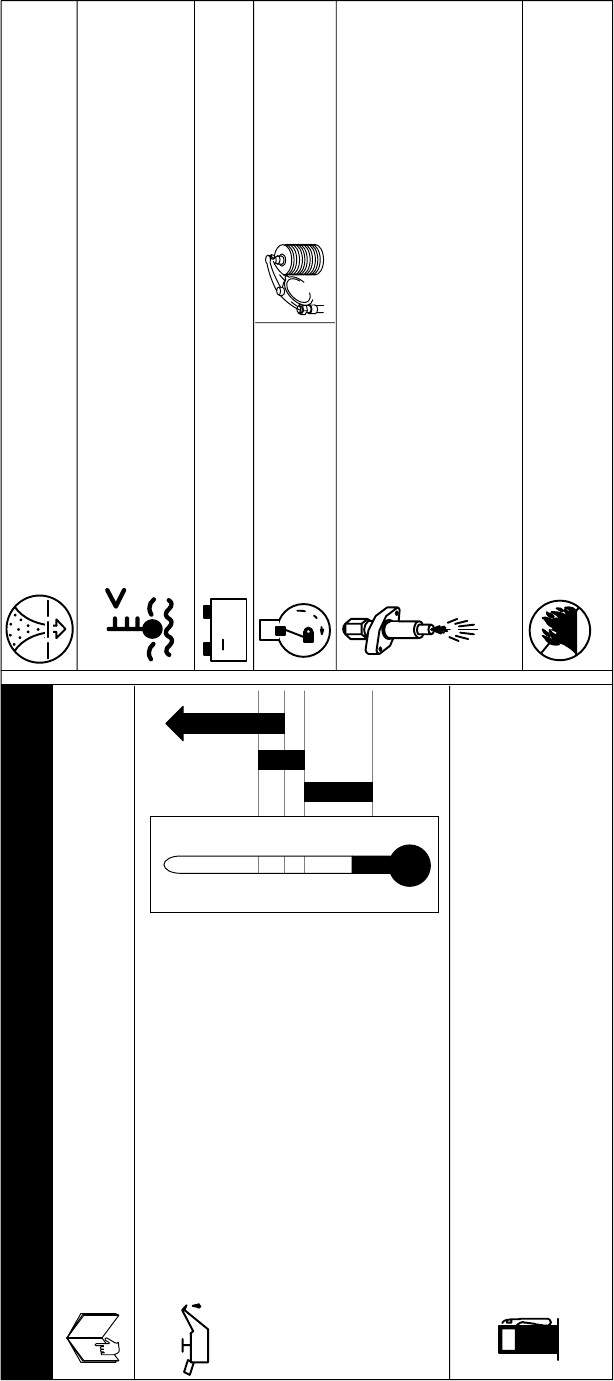
OM-166 941 Page 24
DEUTZ F4L912 DIESEL ENGINE
Check
Recommended Oil API Service Classification CD/CE. . . . .
Oil And Filter Change dirty conditions 100 hours or less. . . . . .
normal conditions 125−150 hours.
Oil Filter MILLER 064 677, Deutz 117-4418,. . . . . . . . . . . . . . Fleetguard LF4056, Fram PH2842,
Hastings P352 or FP352
Oil Capacity 11.5 qt (11 L) or. . . . . . . . . . . 12 qt (11.4 L) with filter change
+
S-146 389-B
Spark Arrestor Inspection And Service 250 operating hours −. . . . . . . . . . see Owner’s Manual
Fuel Capacity 30 gal (113.6 L). . . . . . . . .
Fuel Grade 1-D or 2-D Cetane No. 45 min.. . . . . . . . . . .
Primary Fuel Filter/
Water Seperator MILLER 062 342, Fleetguard FF194, Fram P1107. . . . . . .
Secondary Fuel Filter Deutz 117-4423, Fleetguard FF5018, Fram P4102. . . MILLER 064 686
Fill filter with clean fuel before installing − read instructions on filter.
Engine RPM − No Load
Weld/Power 1850. . . .
Air Filter Service 50 hours or less − see Owner’s Manual. . . . . .
Air Filter Element MILLER 020 319, AC 302C, Donaldson P10-1222,. . . . . Fleetguard AF437K, Fram CAK 253, Purolator AF-2030K
Injectors MILLER 064 684, Deutz 223-3085. . . . . . . . . . . . . .
Nozzle MILLER 064 685, Deutz 223-3086. . . . . . . . . . . . . . .
Have only trained technician maintain injection pump and injectors. AIR, WATER, or
GASOLINE will harm the injection system. If tank is run out of fuel or fuel filter is
changed, bleeding of air is required.
Diesel
See Engine Manual for complete engine care.
Give Engine Specification and Serial Number when ordering parts.
daily.
°C
+30
+20
+10
0
-10
-20
°F
10W
20W-20
+30
-10
+60
30
Battery BCI Group 31. . . . . . . .
Cranking Performance at 0°F (-18°C) 815 Amps. . . . . .
Valve Clearance −Cold
Intake 0.006 in (0.15 mm). . . . .
Exhaust 0.006 in (0.15 mm). . .
Do NOT
use ether.
+40
Engine Cooling
Avoid recirculation of air from hot air exit to blower intake.
Blower Belt Deutz 223-5531, MILLER 064 690. . . . . . . . . . .
Alternator Belt Deutz 223-5179, MILLER 066 213. . . . . . . . .
Compressor Belts (2) Deutz 116-1683. . .
+40
Optional
Figure 8-1. Engine Maintenance Label
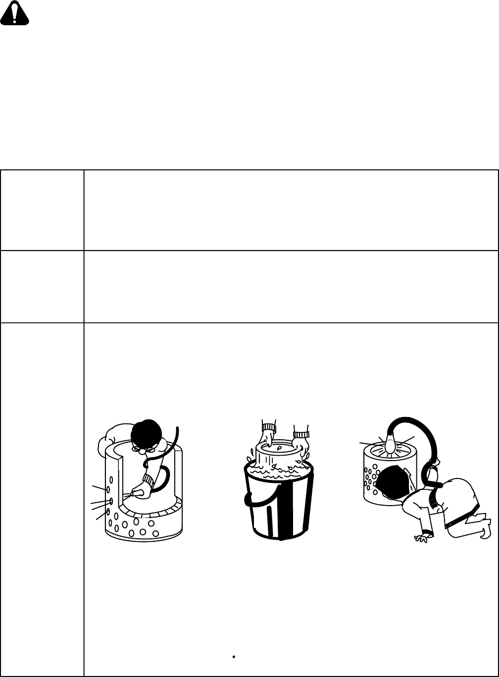
OM-166 941 Page 25
8-2. AIR CLEANER SERVICE (Table 8-2)
CAUTION: DIRTY AIR can damage engine.
•Do not operate engine with dirty air cleaner
element in place.
•Do not operate engine without air cleaner ele-
ment in place.
The air cleaner is one of the most important parts of the
engine from the standpoint of engine life. If dirty air gets
into the engine, it can cause major engine damage
within a few operating hours. The air cleaner must be
serviced when the SERVICE ENGINE AIR CLEANER
Indicator light PL1 comes on. If PL1 comes on, empty
dust cap, and inspect air cleaner and element.
The air cleaner on this unit is equipped with precleaners.
Remove the precleaner cover and empty the dust re-
ceptacle when dirt accumulates up to the indicator
marks on the side of the precleaner.
IMPORTANT: A dirty air cleaner element is usually ac-
companied by a loss of power and excessive smoke in
the engine exhaust.
When it becomes necessary to service the air cleaner in
the field, follow the steps in Table 8-2. Keep a spare ele-
ment on hand for replacement. New elements are avail-
able from your welding equipment distributor.
Table 8-2. Air Cleaner Service
1. Stop engine. 5. Wipe out element chamber 7. Reinstall element.
with clean, damp cloth.
2. Wipe off cover before 8. Replace cover.
opening air cleaner. 6. Inspect new element and all
gaskets for shipping damage before use.
3. Remove cover.
4. Remove element.
1. Don’t attempt to service air 3. Don’t leave open air cleaner exposed 5. For Donaclone air cleaners ,
cleaner with engine running. to blowing dust while you clean element. don’t blow out Donaclone tube
Replace cover. section without element, cover
2. Don’t blow out the inside of and inner cover (if any)
the air cleaner with compressed 4. If air cleaner is horizontally mounted, correctly installed or you will
air. be sure that dust cup is positioned so blow dust into the engine.
arrows point up.
Clean element by one of the re-use. However, washing does (When cleaning Cyclopac
following methods: a better job and must be used when elements, do not remove
exhaust soot has lodged in fine pores plastic fin assembly − back-
Compressed Air or Washing. of the filter media. Use Donaldson D-1400 flowing with compressed air or
detergent which contains a special washing will remove dust from
Compressed air is recommended additive for removing soot and carbon. beneath the fin assembly).
when element will be re-used
immediately because a washed Replace element after 6 cleanings or
element must be dried before annually, whichever occurs first.
Compressed Air Washing Inspection
Direct air through element in 1. Soak element 15 minutes or more Place bright light inside
the direction opposite to normal in Donaldson D-1400 and water solution. element and rotate element
air flow through the element. See carton for full instructions. slowly. If any rupture, holes
Move nozzle up and down while or damaged gaskets are
rotating element. Keep nozzle 2. Rinse until water is clear (Maximum discovered − replace.
at least one inch from pleated water pressure 40 P.S.I.)
paper. Maximum air pressure −
100 P.S.I. 3. Air-dry or use warm flowing air, max.
160 F. Do not use compressed air or
light bulbs.
Follow
These
Easy
Steps:
Important
How To
Clean
Elements
For
Re-Use
S-0091/4-89
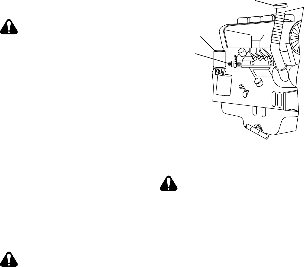
OM-166 941 Page 26
8-3. FUEL/WATER SEPARATOR AND SLUDGE
DRAIN PLUG
WARNING: ENGINE FUEL can cause fire or
explosion.
•Do not drain fuel tank while engine is running.
•Do not smoke while handling fuel.
•Do not allow fuel to drain onto the engine or
other components.
•Do not spill fuel; if spilled, wipe up.
•Have a fire extinguisher nearby, and know
how to use it.
A. Fuel/Water Separator
The fuel/water separator, located on the right base rail
near the engine, is provided to drain off water from the
fuel system. Before starting the engine for the first time
each day, open the fuel drain plug on the bottom of the
separator, and drain the water into a metal container.
Close the drain plug at the first signs of fuel. The fuel/
water separator should be changed every 125 hours of
operation or every four months, whichever occurs first.
B. Sludge Drain Plug
A sludge drain plug, located on the lower right front cor-
ner of the unit, is provided to drain off sediment from the
fuel tank. Once a week, drain the sludge into a metal
container. If the fuel is extremely dirty, drain the sludge
daily.
8-4. FUEL FILTER (Figure 8-2)
WARNING: ENGINE FUEL can cause fire or
explosion.
•Stop engine before working on fuel system.
•Do not spill fuel; if spilled wipe up.
•Do not service fuel filter if engine is hot or run-
ning.
•Do not service fuel filter near sparks or open
flame.
•Do not smoke while servicing fuel filter.
•Have a fire extinguisher nearby, and know
how to use it.
This welding generator is equipped with a cartridge-type
fuel filter located above the oil filter on the right side of
the unit. The fuel filter should be replaced after 1000
hours of operation, or more often depending on the qual-
ity of fuel used and how dusty and dirty the location is in
which the engine is being used. To replace the fuel filter,
refer to the Engine Manufacturer’s Manual.
Oil Fill Cap
Fuel Filter
Engine Speed
Adjustment
Screw
Ref. ST-147 321-A
Figure 8-2. Right Side And Rear View Of Engine
8-5. BATTERY REPLACEMENT PROCEDURE
WARNING: SPARKS OR FLAMES can cause
BATTERY GASES to explode; BATTERY
ACID can burn eyes and skin.
•Stop engine before disconnecting or
connecting battery cables.
•Keep sparks, flames, cigarettes, and other
ignition sources away from batteries.
•Do not allow tools to cause sparks when
working on a battery.
•Always wear a face shield and proper
protective gloves and clothing when working
on a battery.
Use the following procedure to prevent sparks when
removing or installing a battery:
1. Be sure engine is fully stopped, and Engine
Control switch is in the OFF position.
2. Locate battery in unit.
3. Open door or remove panels as necessary.
4. Disconnect negative (−) battery cable first and
positive (+) cable last.
5. Remove holddown device.
6. Remove battery.
7. Install new (or charged) battery.
8. Reinstall and secure holddown device.
9. Connect positive (+) cable first and negative (−)
cable last.
10. Securely reinstall or close doors or panels.

OM-166 941 Page 27
8-6. MAINTENANCE-FREE BATTERY CHARG-
ING
WARNING: CHARGING A FROZEN BAT-
TERY can cause the battery to explode and
result in serious personal injury or damage
to equipment.
• Allow battery to warm up to 60° F (16°C) be-
fore charging if battery is frozen.
BATTERY ACID can burn eyes and skin and
destroy clothing and other materials; BAT-
TERY GASES can explode and shatter bat-
tery.
•Wear a face shield, proper protective cloth-
ing, and remove all metal jewelry.
•Do not spill or splash battery fluid.
•Do not apply pressure to walls of filled bat-
tery—use battery carrier or place hands on
opposite corners when lifting battery.
•Keep sparks, flames, cigarettes, and other ig-
nition sources away from batteries.
•Use enough ventilation to keep battery gases
from building up during and for several hours
after battery charging.
•Do not touch or move connections on battery
while battery charger is on.
•Turn battery charger off before making con-
nections to battery.
•Do not lean over battery when charging.
•Be sure battery charger connections to bat-
tery are clean and tight.
•Keep vent caps in place and cover top of bat-
tery with damp cloth.
•Be sure battery charger output matches bat-
tery voltage.
•Turn the battery charger off before discon-
necting the charger from the battery.
1. Remove battery from unit, and place on a level
worktable or other suitable surface.
2. If battery has removable vent caps, check the
condition of the electrolyte as follows:
a. Check electrolyte temperature in one of the
center cells with a battery thermometer. For
each 10°F (6°C) increment above 80°F (27°C),
a correction factor of 0.004 specific gravity
must be added to the specific gravity reading
taken in Step 2b. For each 10°F (6°C) incre-
ment below 80°F (27°C), 0.004 must be sub-
tracted from the reading taken in Step 2b.
b. Check the specific gravity of each cell with a hy-
drometer. (Draw in and expel the electrolyte two
or three times from the first cell to be tested to
adjust the temperature of the hydrometer to
that of the electrolyte.)
c. If a corrected specific gravity reading of 1.225 at
80°F (27°C) is not obtained, replace the vent
caps and recharge the battery following the bat-
tery charger manufacturer’s instructions.
3. If the battery does not have removable vent caps,
check the condition of the battery as follows:
a. Check the stabilized open−circuit voltage of the
battery. For a 12 volt battery, any reading below
12.4 volts indicates the battery needs charging.
Disconnect both battery cables from the bat-
tery, and allow battery voltage to stabilize for
several hours.
b. If the stabilized open−circuit voltage is below
12.4 volts, charge the battery following the bat-
tery charger manufacturer’s instructions.
4. Remove damp cloth from battery.
5. Reinstall battery in unit.
6. Replace battery holddown, and tighten securely.
Do not overtighten.
7. Connect positive (+) battery cable to positive (+)
battery terminal.
8. Connect negative (−) battery cable to negative
(−) battery terminal.
8-7. GOVERNOR
The governor has been set at the factory and should not
require further adjustment.
8-8. ENGINE SPEED ADJUSTMENTS (Figure 8-2)
WARNING: ELECTRIC SHOCK can kill.
•Do not touch live electrical parts.
•Stop engine, and disconnect negative (−)
battery cable from battery before inspecting,
maintaining, or servicing.
MOVING PARTS can cause serious injury.
•Keep away from moving parts such as fans,
belts, and rotors.
HOT ENGINE PARTS can cause severe
burns.
•Wear protective gloves and clothing when
working on a hot engine.
Maintenance to be performed only by qualified
persons.
The engine speeds have been factory adjusted and
should not require frequent readjustment. After tuning
the engine, check the speeds with a tachometer. With
no load applied, the weld/power speed should be 1860
rpm. If necessary, adjust the speeds as follows:
1. Open and secure right rear side door.
2. Loosen nut on end of engine speed adjusting
screw (see Figure 8-2).
3. Start the engine as instructed in Section 7-6.
4. Adjust the weld/power speed as follows:
IMPORTANT: All directions, such as clockwise and
counterclockwise, are with respect to the operator fac-
ing the rear panel of the unit.
a. To increase weld/power speed, rotate the en-
gine speed adjustment screw clockwise.
b. To decrease weld/power speed, rotate the en-
gine adjustment screw counterclockwise.
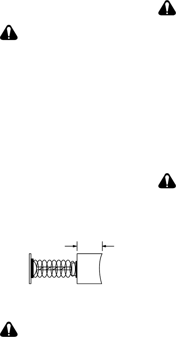
OM-166 941 Page 28
5. When the weld/power speed reaches 1860 rpm,
prevent the adjustment screw from turning, and
tighten the securing nut.
6. Stop engine.
7. Close and secure side door.
8-9. BRUSHES AND SLIP RINGS (Figure 8-3)
WARNING: ELECTRIC SHOCK can kill
•Do not touch live electrical parts.
•Stop engine, and disconnect negative (−) bat-
tery cable from battery before inspecting,
maintaining, or servicing.
MOVING PARTS can cause serious injury.
•Keep away from moving parts such as fans,
belts, and rotors.
HOT ENGINE PARTS can cause severe
burns.
•Wear protective gloves and clothing when
working on a hot engine.
Brush life is very good under most operating conditions.
The brushes and slip rings should be inspected every
six months or whenever excitation voltage is lost. Be
sure that slip rings are clean and brushes are free to
move. If the welding generator has been operating un-
der extremely dusty or dirty conditions, increase the fre-
quency of inspection.
Under normal use, the slip rings will discolor to a dark
brown. If a buildup of brush material is noted, it may be
necessary to clean the slip rings. Clean rings with a
number 220 or finer sandpaper, and polish rings with
crocus cloth. Never use emery cloth because part of the
emery will embed itself into the rings and, in turn, de-
stroy the carbon brushes.
Replace the brushes if they become chipped or broken
or if less than 1/2 in. (12.7 mm) of brush material is left.
1/2 in. (12.7 mm)
Minimum
S-0234
Figure 8-3. Brush Replacement
8-10. ETHER STARTING AID (Optional)
CAUTION: ETHER INJECTION WHILE
ENGINE IS RUNNING can cause engine
damage.
•Do not actuate ETHER STARTING AID while
engine is running.
The ether used in the cold weather starting aid system is
contained in a replaceable cylinder located behind the
right rear side door on the center portion of the frame.
No indicator is provided to show the amount of ether left
in the cylinder; therefore, it is recommended that a spare
cylinder be kept on hand. Generally, the ether cylinder is
empty if the engine fails to start in cold weather while uti-
lizing the cold weather starting system.
WARNING: IMPROPER HANDLING OR EX-
POSURE TO ETHER can seriously harm
your health.
•Follow the manufacturer’s safety instructions
on the cylinder when handling ether compo-
nents.
The cylinder can be weighed to determine the amount
of ether inside. The cylinder weighs 33 ounces (936 gr)
when full, and it weighs 15 ounces (425 gr) when empty.
To replace the ether cylinder, see Section 4-10.
IMPORTANT: Before installing the ether cylinder, clean
nozzle on ether cylinder and fitting into which the ether
cylinder is inserted. If dirt is present in either of these ar-
eas, the system may not work.
IMPORTANT: After installing or replacing ether cylin-
der, do not use or test ether start system for at least 10 to
15 minutes to allow particles in fuel to settle to prevent
atomizer plugging.
8-11. SPARK ARRESTOR
WARNING: ELECTRIC SHOCK can kill.
•Do not touch live electrical parts.
•Stop engine and disconnect negative (−)
battery cable from battery before beginning
this installation.
MOVING PARTS can cause severe injury.
•Keep away from moving parts such as fans,
belts, and rotors.
ENGINE EXHAUST SPARKS can cause fire.
•Exhaust spark arrestor must be installed in
accordance with local, state, and federal
regulations.
•Stop engine before cleaning spark arrestor.
•Clean spark arrestor in a noncombustible
environment.
HOT PARTS can cause severe burns.
•The exhaust system must be cold when
servicing the spark arrestor.
Internal combustion engines operating in a highly com-
bustible environment are a common fire hazard. Glow-
ing carbon particles blown out with the exhaust can re-
tain sufficient heat to ignite materials. While no practical
spark arresting device will stop all sparks, this device will
minimize fire hazards by removing and trapping most
solid particles provided that is is properly maintained.
Inspect and service spark arrestor every 250 operation
hours.

OM-166 941 Page 29
Removal of the device from the exhaust system is not
necessary for servicing. Proceed as follows to service
spark arrestor:
1. Stop the engine, and allow the exhaust system to
cool.
2. Remove the cleanout plug from the bottom of the
spark arrestor. If a crust has formed over the
hole, break it loose with a screwdriver or similar
tool.
3. Start the engine, and run it at idle rpm to blow col-
lected particles out the cleanout hole. If particles
are slow to discharge, momentarily cover the end
of the exhaust stack.
4. Stop the engine, and allow the exhaust system to
cool.
5. Replace and secure the cleanout plug.
8-12. RUN-IN PROCEDURE
WARNING: ELECTRIC SHOCK can kill.
•Do not touch live electrical parts.
•Stop engine before inspecting, connecting,
or servicing.
•Do not leave live unit unattended when
engine is running.
•Keep all panels, covers, and guards
securely in place while engine is running.
MOVING PARTS can cause severe injury.
•Keep away from moving parts such as fans,
belts, and rotors.
HOT ENGINE PARTS can cause severe
burns.
•Wear protective gloves and clothing when
working on hot engine parts or components.
CAUTION: LOW OIL LEVEL can damage
engine; ENGINE MAY USE OIL AND WETS-
TACKING may occur during run-in period.
•Check oil level several times a day during
run-in period, and add oil if required.
•See engine Owner’s Manual (Deutz
F4L-912 diesel engine) for run-in informa-
tion.
•Do not idle engine longer than necessary
during run-in period.
•Piston rings seat faster if engine runs at
weld/power rpm, and the welding generator
is kept loaded during the run-in period.
The run-in procedure for diesel engines is different than
those associated with gasoline engines. Diesel engines
must be run at near-rated load during the run-in period to
ensure proper seating of piston rings and to prevent
wetstacking. Wetstacking is an accumulation of un-
burned fuel and oil in the exhaust pipe. Wetstacking can
occur during the run-in period if the engine is left at idle
rpm too long, or the welding generator is not heavily
loaded.
If wetstacking occurs, complete one of the following pro-
cedures to dry the engine (see engine Owner’s Manual,
F4L-912 diesel engine). A resistance load is required to
fully load the generator during the run-in procedure. A
load bank or resistance grid may provide a constant load
for run-in, however, a load bank is preferred. If a load
bank is available, proceed with the run-in procedure pro-
vided in Subsection A. If a resistance grid is being used,
proceed to Subsection B.
A. Run-In Procedure Using Load Bank (Diagram
8-1)
WARNING: Read and follow safety infor-
mation at beginning of entire Section 8-12
before proceeding.
1. Stop engine.
IMPORTANT: Weld cables supplied with load bank may
be inadequate for run-in procedure. Use weld cables of
proper size with appropriate connectors to connect load
bank to generator (see load bank Owner’s Manual).
2. Connect cables from load bank to generator weld
output terminals observing correct polarity (see
Diagram 8-1).
3. Place all load switches in the OFF position.
IMPORTANT: If load bank requires 115 volts ac, it may
be connected to the welding generator auxiliary power
terminal strip, if applicable.
4. Place welding generator AMPERAGE & VOLT-
AGE ADJUSTMENT control in the minimum po-
sition.
5. Start engine as instructed in Section 7-6, and al-
low engine to warm up for approximately three
minutes.
6. Adjust load bank switches and generator controls
to provide a load equal to rated generator output.
For example, if rated generator output is 350 am-
peres, 40 volts at 100% duty cycle, adjust
switches until values indicated by load meters
equal rated generator output.
7. Allow engine to run under load for at least one
hour. Check engine and load bank meters after
the first five minutes and every 15 minutes there-
after to be sure equipment is operating properly.
8. After running engine under load for at least one
hour, remove load by shutting down load bank.
9. Allow engine to idle for approximately three min-
utes to permit internal engine temperatures to
equalize.
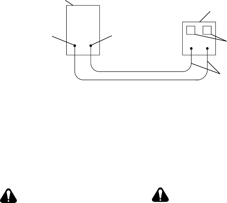
OM-166 941 Page 30
+− +−
Welding
Generator
Load Bank
Voltmeter
And
Ammeter
Weld
Cables
Negative (−)
Weld Output
Terminal
Positive (+)
Weld Output
Terminal
S-0456
Diagram 8-1. Load Bank Connections
10. Stop engine, and disconnect load bank cables.
11. Allow exhaust system to cool.
12. Inspect inside of exhaust pipe. If pipe is dry, the
run-in procedure is complete. If pipe is coated
with a wet, black, tar-like substance, repeat run-
in procedure.
B. Run-In Procedure Using Resistance Grid (Dia-
gram 8-2)
WARNING: Read and follow safety infor-
mation at beginning of entire Section 8-12
before proceeding.
1. Stop engine.
2. Obtain resistance grid adequately sized for rated
output of welding generator.
3. Obtain two weld cables of proper size to connect
resistance grid to generator (see Section 4-7).
4. If a voltmeter and ammeter are not provided on
the welding generator, obtain a voltmeter and
clamp-on dc ammeter.
5. Place welding generator AMPERAGE & VOLT-
AGE ADJUSTMENT control in the minimum po-
sition.
6. Adjust grid switches and generator controls to
provide a load approximately equal to rated gen-
erator output.
For example, if rated generator output is 350 am-
peres, 40 volts at 100% duty cycle, adjust
switches until values indicated by meters equals
rated generator output.
7. Connect one weld cable to grid input receptacle
and remaining weld cable to grid output recep-
tacle (see Diagram 8-2).
8. If a voltmeter and ammeter are provided on the
welding generator, proceed to Step 9. If meters
are not provided, connect voltmeter and clamp-
on dc ammeter as shown in Diagram 8-2.
9. Connect remaining ends of weld cables to gener-
ator weld output terminals (polarity is not impor-
tant).
10. Start engine as instructed in Section 7-6, and al-
low engine to warm up for approximately three
minutes.
CAUTION: ARCING can damage switch
contacts.
•Do not change the position of the grid
switches while engine is running.
Arcing causes the contacts to become pitted
and eventually inoperative.
11. Check meters. Adjust load with generator con-
trols or, if necessary, by changing positions of grid
switches until values indicated by meters equal
rated generator output.
12. Allow engine to run under load for at least one
hour. Check engine and meters after the first five
minutes and every 15 minutes thereafter to be
sure equipment is operating properly
13. After running engine under load for at least one
hour, remove load by shutting down resistance
grid.
14. Allow engine to idle for approximately three min-
utes to permit internal engine temperatures to
equalize.
15. Stop engine, and disconnect weld cables.
16. Allow exhaust system to cool.
17. Inspect inside of exhaust pipe. If pipe is dry, the
run-in procedure is complete. If pipe is coated
with a wet, black, tar-like substance, repeat run-
in procedure.
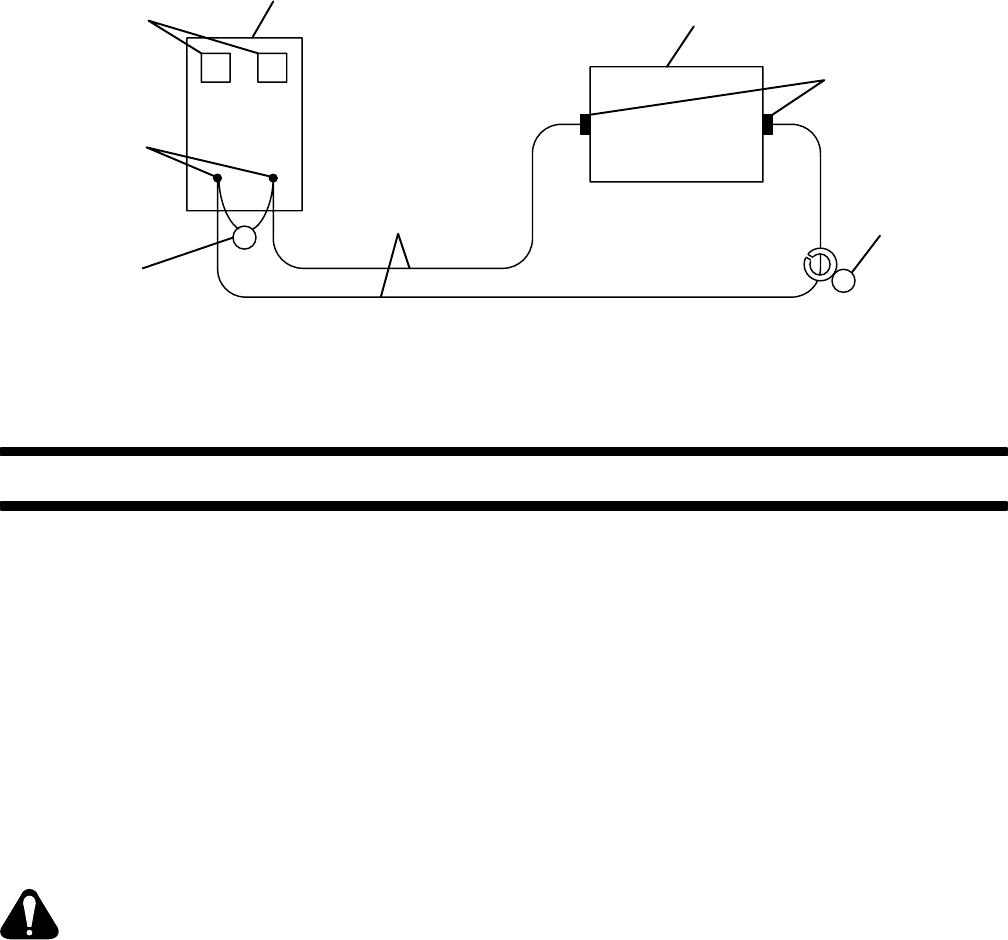
OM-166 941 Page 31
A
V
Welding
Generator
Resistance Grid
Input And Output
Receptacles
Weld
Cables
Voltmeter And
Ammeter
(If so equipped)
Weld Output
Terminals
(Polarity Not
Important)
♦Voltmeter
♦Clamp-On
DC Ammeter
♦Required if welding generator is not equipped with meters.
S-0457
Diagram 8-2. Resistance Grid Connections
SECTION 9 − TROUBLESHOOTING
9-1. GENERAL
It is assumed that proper installation has been made,
according to Section 4 of this manual, the operator is fa-
miliar with the function of controls, the welding generator
was functioning properly, and the trouble is not related to
the welding process.
9-2. BOOSTER BATTERY JUMP STARTING
If it is necessary to jump start this unit, use the following
safety precautions and the step-by-step procedures in
order of appearance.
WARNING: BATTERY GASES OR A DAM-
AGED BATTERY can explode thereby shat-
tering the battery; BATTERY ACID can burn
eyes, skin, destroy clothing, and damage
other material; MOVING PARTS AND IM-
PROPER CONNECTIONS can cause serious
personal injury and damage equipment.
•Keep sparks, flames, cigarettes, and other ig-
nition sources away from battery.
•Ensure that all personnel are a safe distance
from batteries and clear of moving parts while
starting.
•Do not jump start a frozen or completely dis-
charged battery.
•Do not jump start a battery which has loose
terminals or one having evidence of damage
such as a cracked case or cover.
•Be sure that vent caps are tight and level on
both batteries and cover both batteries with a
damp cloth.
•Wear correct eye and body protection, and
remove all metal jewelry.
•Keep jumper cables clear of moving parts.
•Ensure that both batteries are of the same
voltage.
•Do not jump start a trailer mounted welding
generator with the towing vehicle battery un-
less the trailer is completely disconnected
from the towing vehicle.
•Do not jump start a vehicle mounted welding
generator from the vehicle battery.
•If booster battery is installed in vehicle, do not
allow vehicle to make contact with welding
generator case or frame.
•Do not jump start by applying power to weld
output receptacles or terminals.
•Do not allow jumper cables to contact any
other metal while attaching or removing ca-
bles.
1. Use properly insulated jumper cables of ade-
quate size.
2. Connect ends of one cable to positive (+) termi-
nals of each battery.
3. Connect one end of other cable to negative (−)
terminal of booster battery.
4. Connect remaining end of cable to welding gen-
erator engine block at least 18 inches (457 mm)
from battery (do not connect to welding generator
case, frame, or equipment grounding terminal as
damage to equipment can result).
5. Wait at least one minute after connecting cables
before starting engine.

OM-166 941 Page 32
6. Start engine following procedures outlined in
Section 7 (Sequence of Operation) of this man-
ual. If the unit does not start after cranking for
twenty seconds, stop the jump starting proce-
dure. More than twenty seconds seldom starts
the engine unless some mechanical adjustment
is made.
7. Remove jumper cable from engine block.
8. Remove other end of same cable from booster
battery negative (−) terminal.
9. Remove other jumper cable from booster battery
positive (+) terminal.
10. Remove remaining end of cable from welding
generator battery positive (+) terminal.
11. Discard damp cloths.
9-3. OVERLOAD PROTECTION (Figure 4-2)
WARNING: ELECTRIC SHOCK can kill.
•Do not touch live electrical parts.
•Stop engine, and disconnect negative (−) bat-
tery cable from battery before inspecting,
maintaining, or servicing.
MOVING PARTS can cause serious personal
injury.
•Keep away from moving parts such as fans,
belts, and rotors.
HOT ENGINE PARTS can cause severe
burns.
•Wear protective gloves and clothing when
working on a hot engine.
INCORRECT FUSE can damage unit.
•Be sure replacement fuse is same size, type,
and rating.
A. Circuit Breaker CB1 (Figure 4-2)
WARNING: Read and follow safety informa-
tion at beginning of Section 9-3 before pro-
ceeding.
Circuit breaker CB1 protects the 120 volts ac auxiliary
power terminals on terminal strip 3T from overload. CB1
is located behind the lower front door. When CB1 opens,
the ON/OFF switch goes to the OFF position, and 3T will
not operate. If CB1 opens, locate and correct the prob-
lem, and place the circuit breaker switch in the ON posi-
tion.
B. Circuit Breaker CB3 (Figure 4-2)
WARNING: Read and follow safety informa-
tion at beginning of Section 9-3 before pro-
ceeding.
Circuit breaker CB3 protects the unit wiring from over-
load and damage. CB3 is located behind the lower front
door.
If CB3 opens, 115 volts ac output to socket/terminal D of
REMOTE 9 receptacle RC3 and terminal strip 3T stops,
and the remote amperage/voltage control will not
function.
C. Replacement Of Low Oil Pressure/High Oil
Temperature Shutdown System Fuse F
WARNING: Read and follow safety informa-
tion at beginning of Section 9-3 before pro-
ceeding.
1. Remove securing screws, and open upper front
access door.
2. Locate shutdown switch MS1 on left, rear side of
front access door.
3. Locate fuse F on bottom of shutdown switch
MS1.
4. Remove and check fuse, and replace if neces-
sary.
5. Close and secure front access door.
9-4. CIRCUIT BOARD HANDLING PRECAU-
TIONS
WARNING: ELECTRIC SHOCK can kill
•Do not touch live electrical parts.
•Stop engine, and disconnect negative (−) bat-
tery cable from battery before inspecting,
maintaining, or servicing.
HOT ENGINE PARTS can cause severe
burns.
•Wear protective gloves and clothing when
working on a hot engine.
CAUTION: ELECTROSTATIC DISCHARGE
(ESD) can damage circuit board compo-
nents.
•Put on properly grounded wrist strap BE-
FORE handling circuit boards.
•Transport all static−sensitive components in
proper static-shielding carriers or packages.
•Perform work only at a static−safe work area.
INCORRECT INSTALLATION or misaligned
plugs can damage circuit board.
•Be sure that plugs are properly installed and
aligned before closing access door.
EXCESSIVE PRESSURE can break circuit
board.
•Use only minimal pressure and gentle move-
ment when disconnecting or connecting
board plugs and removing or installing board.
If any circuit board is not working, follow the precautions
above, and contact the nearest Factory Authorized Ser-
vice Station/Service Distributor.

OM-166 941 Page 33
9-5. TROUBLESHOOTING (Tables 9-1 Thru 9-4)
WARNING: ELECTRIC SHOCK can kill.
•Do not touch live electrical parts.
•Stop engine, and disconnect the negative (−)
battery cable before inspecting, maintaining,
or servicing.
MOVING PARTS can cause serious injury.
•Keep away from moving parts such as fans,
and rotors.
HOT ENGINE PARTS can cause severe
burns.
•Wear protective gloves and clothing when
working on a hot engine.
Troubleshooting to be performed only by quali-
fied persons.
The following tables are designed to diagnose and pro-
vide remedies for some of the troubles that may develop
in this welding generator.
Use these tables in conjunction with the circuit diagram
while performing troubleshooting procedure. If the
trouble is not remedied after performing these proce-
dures, contact the nearest Factory Authorized Service
Station/Service Distributor. In all cases of equipment
malfunction, strictly follow the manufacturer’s proce-
dures and instructions.
Table 9-1. Weld/Power Troubleshooting
TROUBLE PROBABLE CAUSE REMEDY
No weld output. Amperage Ranges switch S9
between positions. Place S9 in LOW OUTPUT or HIGH OUTPUT
position (see Section 6-1).
OUTPUT (CONTACTOR)
switch S5 in REMOTE position
and Remote Contactor device
not connected.
Place S5 in ON position, or install Remote Con-
tactor Control device.
Incorrect or poor connection to
REMOTE 9 receptacle or termi-
nal strip 3T.
Check and secure connections (see Section
4-8).
Circuit breaker CB3 open
(GMAW only). Reset CB3 (see Section 9-3).
Poor contact between slip rings
and brushes. Clean slip rings (see Section 8-9).
Replace brushes according to Section 8-9.
Field Current Regulator board
PC1. See Section 9-4, and contact nearest Factory
Authorized Service Station/Service Distributor.
Erratic weld output. Loose or dirty connections. Check connections both inside and outside the
unit.
Connection at work. Check connection. Be sure connection is clean
and tight.
Damp electrode. Use dry, properly stored electrode.
Field Current Regulator board
PC1. See Section 9-4, and contact nearest Factory
Authorized Service Station/Service Distributor.
Electrode polarity. See Section 4-7C.
High welding output voltage. High engine speed. Check and adjust engine speed according to
Section 8-8.
Field Current Regulator board
PC1. See Section 9-4, and contact nearest Factory
Authorized Service Station/Service Distributor.
Wire feeder inoperative. Circuit breaker CB3. Reset CB3 according to Section 9-3.

OM-166 941 Page 34
Table 9-2. Auxiliary Power Troubleshooting
AUXILIARY POWER
TROUBLE PROBABLE CAUSE REMEDY
No 120 volt output at 3T termi-
nals L and M. Circuit breaker CB1 open. Reset CB1 (see Section 9-3).
Poor contact between slip
rings and brushes. Clean slip rings (see Section 8-9).
Replace brushes according to Section 8-9.
High auxiliary power output
voltage. High engine speed. Check and adjust engine speed according to
Section 8-8. (Maximum voltages should not
exceed 132 volts for single-phase power.)
Table 9-3. Engine Troubleshooting
TROUBLE PROBABLE CAUSE REMEDY
Engine does not start. Out of fuel. Fill fuel tank, and air vent fuel system (see En-
gine Manufacturer’s Manual.)
Battery problem. Check engine battery charging system accord-
ing to engine service manual (not supplied with
engine).
Inspect electrical system (see Section 8-1). If
trouble is isolated to battery, replace it.
Jump start the engine using approved safety
practices and booster battery (see Section
9-2).
Engine Control switch S1. Check S1, and replace if necessary.
Oil Pressure gauge/switch or
Oil Temperature gauge/switch
activated, or other engine
trouble.
See Sections 6-10 thru 6-11; see Engine Man-
ufacturer’s Manual (F4L-912 engine).
MS1 fuse F. Check and replace F, if necessary (see Sec-
tion 9-3).
Engine suddenly shuts down. Broken cooling belt. Check and replace belt (see Section 6-15).
High oil temperature. Check engine oil level and add oil if necessary;
check for cooling air flow obstructions.
Low oil pressure. Check engine oil level, and add oil if necessary
(see Section 4-5).
MS1 fuse F. Check and replace F if necessary (see Section
9-3).
Table 9-4. Air Compressor Troubleshooting
AIR COMPRESSOR
TROUBLE CAUSE REMEDY
Air compressor fails to build
pressure or builds pressure
slowly.
Engine air compressor. Service air compressor. Contact nearest Au-
thorized Service Station/Service Distributor.
Pneumatic tools freeze up. Moisture in compressed air. Induce an antifreeze solution into the air sup-
ply. Contact nearest Authorized Service Sta-
tion/Service Distributor.
OM-166 941 Page 35
NOTES

Diagram 10-1. Circuit Diagram For Welding Generator
OM-166 941 Page 36
SECTION 10 − ELECTRICAL DIAGRAMS
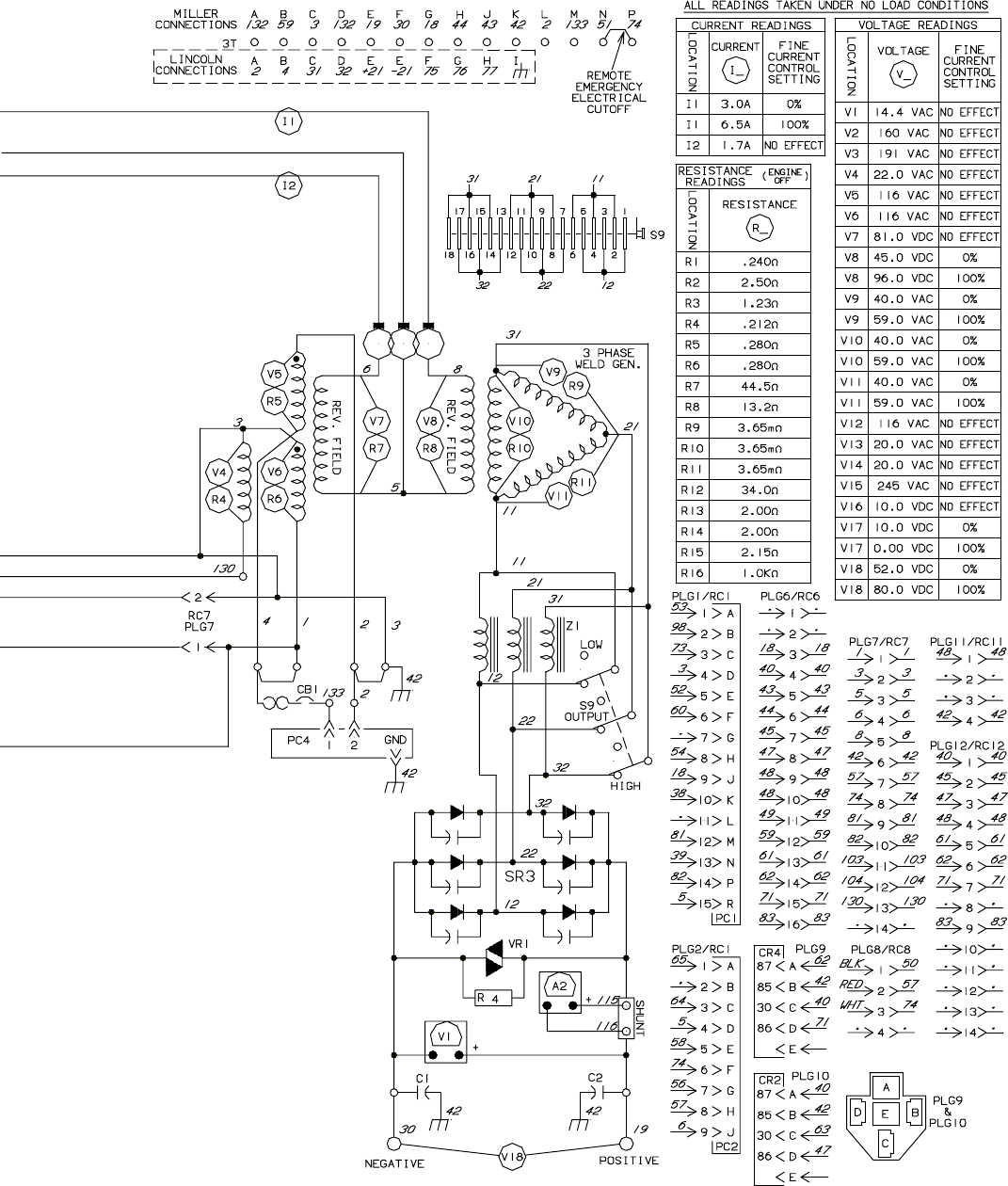
OM-166 941 Page 37
SC-168 908-B
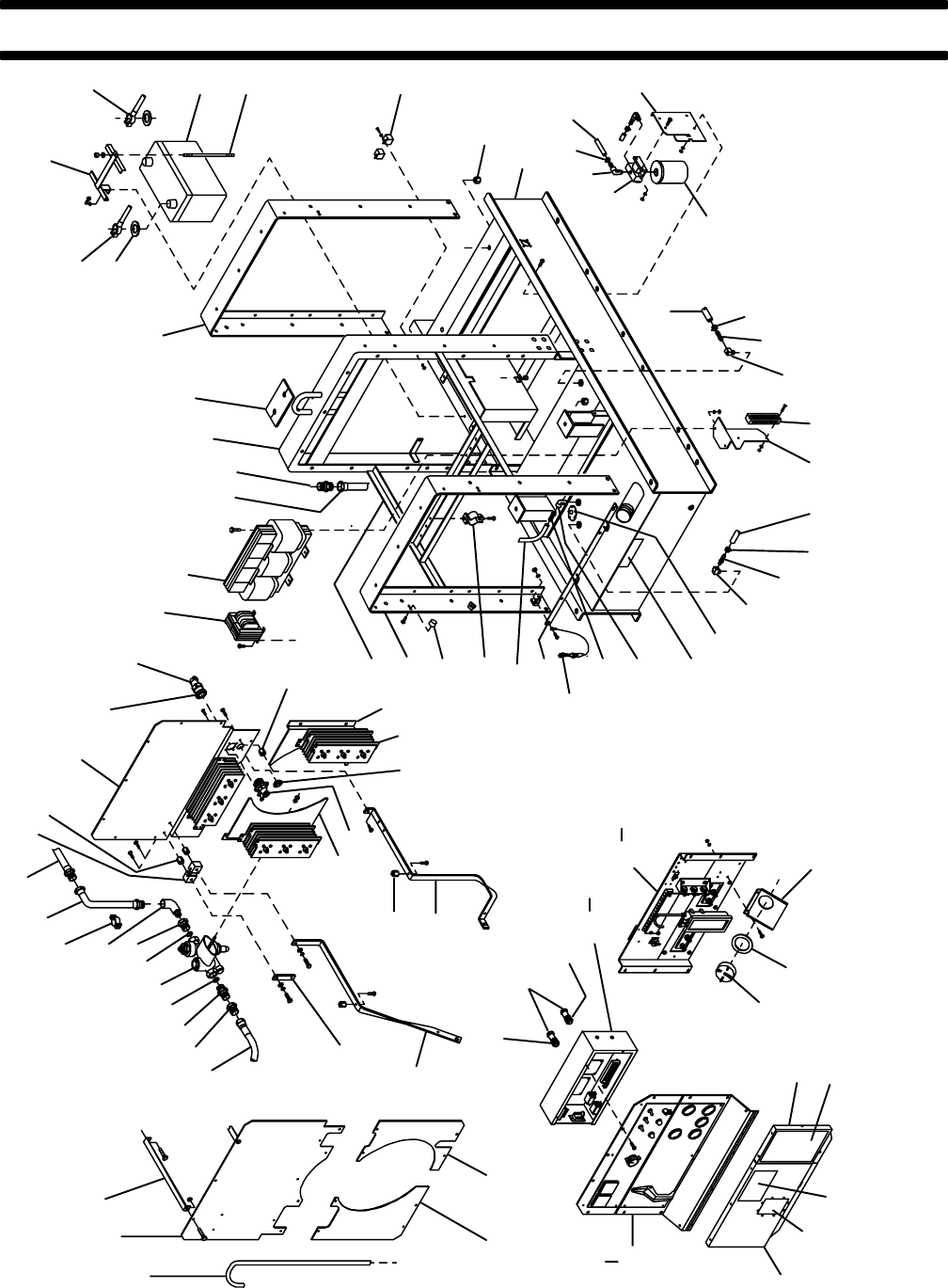
OM-166 941 Page 38
SECTION 11 − PARTS LIST
Figure 11-1A. Main Assembly
1
23
45678
10
11 12 13 14 15
17
18
19 20
21 22 23
24
25
26
27
28
29
30
31
32
33
34 35 36 37
38
39
40
41
42
44
45
46
47
48
49
50 51
52
53
54
55
56
5758
59
60
62
63
ST-800 491-B (1 of 2)
43
16
79
Fig 11-4
Fig
4
1
36 37
42
1
17
64
65
66
67
68
69
70
71
72
74
75
7776
78
79
Fig 11-3
11-2
73
15
61

OM-166 941 Page 39
Part
No.
Dia.
Mkgs.
Figure 11-1A. Main Assembly
Item
No. Description Quanti
ty
1 134 834 HOSE, SAE .187 ID x .410 OD (order by ft) 4ft. . . . . . . . . . . . . . . . . . . . . . . . . . . . . . . . . . . . . . . . . . .
2 131 123 SHIELD, heat upper 1. . . . . . . . . . . . . . . . . . . . . . . . . . . . . . . . . . . . . . . . . . . . . . . . . . . . . . . . . . . . . . .
3 146 240 BRACKET, heat shield 2. . . . . . . . . . . . . . . . . . . . . . . . . . . . . . . . . . . . . . . . . . . . . . . . . . . . . . . . . . . . .
4 1063920009309 HOSE, air 43.000 3/4 swivel both ends 1. . . . . . . . . . . . . . . . . . . . . . . . . . . . . . . . . . . . . . . .
5 0302390009309 FITTING, stl flrd conn fem 1/2tbg x 1/2NPT 1. . . . . . . . . . . . . . . . . . . . . . . . . . . . . . . . . . . .
6 1261610009309 FITTING, pipe brs adapter 1/2NPT x M22 x 1.5 1. . . . . . . . . . . . . . . . . . . . . . . . . . . . . . . . .
7 1448660009309 SEAL, ring copper 2. . . . . . . . . . . . . . . . . . . . . . . . . . . . . . . . . . . . . . . . . . . . . . . . . . . . . . . . . .
8 1448670009309 VALVE, control air 1. . . . . . . . . . . . . . . . . . . . . . . . . . . . . . . . . . . . . . . . . . . . . . . . . . . . . . . . . .
9 1448320009309 FITTING, pipe brs adapter 1/2fem NPT x M22 x 1.5 1. . . . . . . . . . . . . . . . . . . . . . . . . . . . .
10 602 904 FITTING, pipe stl elb st .500NPT 1. . . . . . . . . . . . . . . . . . . . . . . . . . . . . . . . . . . . . . . . . . . . . . . . . . . .
11 010 917 HANGER, minerallic No. 0 3. . . . . . . . . . . . . . . . . . . . . . . . . . . . . . . . . . . . . . . . . . . . . . . . . . . . . . . . . .
12 1224390009309 AIR LINE, tank to exit 1. . . . . . . . . . . . . . . . . . . . . . . . . . . . . . . . . . . . . . . . . . . . . . . . . . . . . . .
13 138 098 HOSE, sst brd 20.750 lg 3/4NPT M ftg x 3/4NPT M INV. . . . . . . . . . . . . . . . . . . . . . . . (same as Item 5 Fig 11-1B) 1. . . . . . . . . . . . . . . . . . . . . . . . . . . . . . . . .
14 Shunt 072 426 SHUNT, meter 50MV 1000A 1. . . . . . . . . . . . . . . . . . . . . . . . . . . . . . . . . . . . . . . . . . . . . . . . .
15 025 248 STAND-OFF, insul .250-20 x 1.250 lg 3. . . . . . . . . . . . . . . . . . . . . . . . . . . . . . . . . . . . . . . . . . . . . . . . .
16 14172390009309 FIREWALL, top 1. . . . . . . . . . . . . . . . . . . . . . . . . . . . . . . . . . . . . . . . . . . . . . . . . . . . . . . . . . .
17 PLG7,12 047 636 CONNECTOR & PINS, (consisting of) 2. . . . . . . . . . . . . . . . . . . . . . . . . . . . . . . . . . . . . . .
079 535 CONNECTOR, circ pin push-in 14-18ga Amp 66359-6 14. . . . . . . . . . . . . . . . . . . . . . . . . . . . . . . . . . . . .
18 143 922 CONNECTOR, circ clamp str rlf sz 17-20 Amp 206070-3 2. . . . . . . . . . . . . . . . . . . . . . . . . . . . . . . .
19 T2 1479850009309 TRANSFORMER, control (consisting of) 1. . . . . . . . . . . . . . . . . . . . . . . . . . . . . . . . . . .
RC8 167 640 CONNECTOR & PINS, (consisting of) 1. . . . . . . . . . . . . . . . . . . . . . . . . . . . . . . . . . . . . . . . . . . . . .
113 633 CONNECTOR, rect pin 20-14ga Amp 350218-1 4. . . . . . . . . . . . . . . . . . . . . . . . . . . . . . . . . . . . . . . . . . .
PLG8 136 810 CONNECTOR & SOCKETS, (consisting of) 1. . . . . . . . . . . . . . . . . . . . . . . . . . . . . . . . . . . . . . .
114 066 CONNECTOR, rect skt 20-14ga Amp 350536-1 4. . . . . . . . . . . . . . . . . . . . . . . . . . . . . . . . . . . . . . . . . . .
20 Z1 1290740009880 REACTOR 1. . . . . . . . . . . . . . . . . . . . . . . . . . . . . . . . . . . . . . . . . . . . . . . . . . . . . . . . . . . . .
21 1107430009309 FITTING, stl flrd conn M 1/2tbg x .750-16 1. . . . . . . . . . . . . . . . . . . . . . . . . . . . . . . . . . . . . .
22 1551670009309 UPRIGHT, center 1. . . . . . . . . . . . . . . . . . . . . . . . . . . . . . . . . . . . . . . . . . . . . . . . . . . . . . . . . . .
601 965 SCREW, .375-16 x 1.000hexhd 2. . . . . . . . . . . . . . . . . . . . . . . . . . . . . . . . . . . . . . . . . . . . . . . . . . . . . . . . .
23 017 479 SEAL, weather lift eye 2. . . . . . . . . . . . . . . . . . . . . . . . . . . . . . . . . . . . . . . . . . . . . . . . . . . . . . . . . . . . . .
24 1551680009309 UPRIGHT, rear 1. . . . . . . . . . . . . . . . . . . . . . . . . . . . . . . . . . . . . . . . . . . . . . . . . . . . . . . . . . . . .
25 108 081 TERMINAL PROTECTOR, battery post mtg 2. . . . . . . . . . . . . . . . . . . . . . . . . . . . . . . . . . . . . . . . . . .
26 134 456 CABLE, bat neg 1. . . . . . . . . . . . . . . . . . . . . . . . . . . . . . . . . . . . . . . . . . . . . . . . . . . . . . . . . . . . . . . . . . .
27 1186440009309 HOLD DOWN, battery 1. . . . . . . . . . . . . . . . . . . . . . . . . . . . . . . . . . . . . . . . . . . . . . . . . . . . . . .
28 032 452 CABLE, bat pos 1. . . . . . . . . . . . . . . . . . . . . . . . . . . . . . . . . . . . . . . . . . . . . . . . . . . . . . . . . . . . . . . . . . .
29 BAT 012 724 BATTERY, stor 12V 550crk 165RSV 1. . . . . . . . . . . . . . . . . . . . . . . . . . . . . . . . . . . . . . . . . . . .
1448270009309 INSULATOR ASSEMBLY, battery 1. . . . . . . . . . . . . . . . . . . . . . . . . . . . . . . . . . . . . . . . . . . . . . . .
30 010 460 STUD, stl .312-18 1. . . . . . . . . . . . . . . . . . . . . . . . . . . . . . . . . . . . . . . . . . . . . . . . . . . . . . . . . . . . . . . . .
31 CR2,4 090 104 RELAY, encl 12VDC SPST 2. . . . . . . . . . . . . . . . . . . . . . . . . . . . . . . . . . . . . . . . . . . . . . . . . . .
PLG9,10 148 850 SOCKET, relay 5 pin 2. . . . . . . . . . . . . . . . . . . . . . . . . . . . . . . . . . . . . . . . . . . . . . . . . . . . . . . . .
32 601 851 NUT, stl slf lkg hex reg .625-18 4. . . . . . . . . . . . . . . . . . . . . . . . . . . . . . . . . . . . . . . . . . . . . . . . . . . . . .
33 1169780009309 BASE 1. . . . . . . . . . . . . . . . . . . . . . . . . . . . . . . . . . . . . . . . . . . . . . . . . . . . . . . . . . . . . . . . . . . . .
34 083 553 BASE, filter fuel w/adapter 1. . . . . . . . . . . . . . . . . . . . . . . . . . . . . . . . . . . . . . . . . . . . . . . . . . . . . . . . . .
35 145 281 FITTING, hose brs barb elb M 3/8tbg x 1/4NPT 2. . . . . . . . . . . . . . . . . . . . . . . . . . . . . . . . . . . . . . . .
36 099 542 CLAMP, hose .645-.828clp dia 3. . . . . . . . . . . . . . . . . . . . . . . . . . . . . . . . . . . . . . . . . . . . . . . . . . . . . . .
37 134 836 HOSE, SAE .375 ID x .620 OD (order by ft) 7ft. . . . . . . . . . . . . . . . . . . . . . . . . . . . . . . . . . . . . . . . . . .
023 562 CLAMP, hose .312-.875clp dia 2. . . . . . . . . . . . . . . . . . . . . . . . . . . . . . . . . . . . . . . . . . . . . . . . . . . . . . . . . .
38 117 227 BRACKET, mtg fuel filter 1. . . . . . . . . . . . . . . . . . . . . . . . . . . . . . . . . . . . . . . . . . . . . . . . . . . . . . . . . . . .
39 *062 342 SEPARATOR, fuel filter & water 1. . . . . . . . . . . . . . . . . . . . . . . . . . . . . . . . . . . . . . . . . . . . . . . . . . . .
40 089 120 CLAMP, hose .375-.450clp dia 1. . . . . . . . . . . . . . . . . . . . . . . . . . . . . . . . . . . . . . . . . . . . . . . . . . . . . . .
41 073 433 FITTING, brs barbed M 3/16tbg x 1/4NPT 2. . . . . . . . . . . . . . . . . . . . . . . . . . . . . . . . . . . . . . . . . . . .
42 1194860009309 TUBE, pick-up fuel 2. . . . . . . . . . . . . . . . . . . . . . . . . . . . . . . . . . . . . . . . . . . . . . . . . . . . . . . . . .
43 2T 163 656 BLOCK, term 65A 12P 1. . . . . . . . . . . . . . . . . . . . . . . . . . . . . . . . . . . . . . . . . . . . . . . . . . . . . . . . .
44 0570560009309 BRACKET, mtg term strip 1. . . . . . . . . . . . . . . . . . . . . . . . . . . . . . . . . . . . . . . . . . . . . . . . . . . .
45 081 646 FITTING, brs barbed M 3/8tbg x 1/4NPT 1. . . . . . . . . . . . . . . . . . . . . . . . . . . . . . . . . . . . . . . . . . . . . .
46 146 357 SENDER, fuel gauge 11.000 deep 1. . . . . . . . . . . . . . . . . . . . . . . . . . . . . . . . . . . . . . . . . . . . . . . . . . .
47 121 823 LABEL, warning do not lift from this end 1. . . . . . . . . . . . . . . . . . . . . . . . . . . . . . . . . . . . . . . . . . . . . .
48 010 678 FITTING, pipe brs elb st 1/4NPT LH 1. . . . . . . . . . . . . . . . . . . . . . . . . . . . . . . . . . . . . . . . . . . . . . . . .

OM-166 941 Page 40
Part
No.
Dia.
Mkgs.
Figure 11-1A. Main Assembly (Continued)
Item
No. Description Quanti
ty
49 073 433 FITTING, brs barbed M 3/16tbg x 1/4NPT 1. . . . . . . . . . . . . . . . . . . . . . . . . . . . . . . . . . . . . . . . . . . .
50 0456660009309 LATCH, door snap 2. . . . . . . . . . . . . . . . . . . . . . . . . . . . . . . . . . . . . . . . . . . . . . . . . . . . . . . . . .
51 1187900009309 ANGLE, strain relief 1. . . . . . . . . . . . . . . . . . . . . . . . . . . . . . . . . . . . . . . . . . . . . . . . . . . . . . . . .
52 010 914 HANGER, minerallic No. 5 1. . . . . . . . . . . . . . . . . . . . . . . . . . . . . . . . . . . . . . . . . . . . . . . . . . . . . . . . . .
53 087 341 BUMPER, door 1.000 OD x .750 high 6. . . . . . . . . . . . . . . . . . . . . . . . . . . . . . . . . . . . . . . . . . . . . . . .
54 1551660009309 UPRIGHT, front 1. . . . . . . . . . . . . . . . . . . . . . . . . . . . . . . . . . . . . . . . . . . . . . . . . . . . . . . . . . . .
121 699 SPACER, cover 3. . . . . . . . . . . . . . . . . . . . . . . . . . . . . . . . . . . . . . . . . . . . . . . . . . . . . . . . . . . . . . . . . . . . . .
601 965 SCREW, .375-16 x 1.000hexhd (used on fuel filter bracket also) 4. . . . . . . . . . . . . . . . . . . . . . . . . . . .
602 213 WASHER, lock stl split .375 (used on fuel filter bracket also) 4. . . . . . . . . . . . . . . . . . . . . . . . . . . . . . . .
601 871 NUT, stl hex jam .375-16 (used on fuel filter bracket also) 4. . . . . . . . . . . . . . . . . . . . . . . . . . . . . . . . . .
55 1311880009309 FRAME, mtg reactor 1. . . . . . . . . . . . . . . . . . . . . . . . . . . . . . . . . . . . . . . . . . . . . . . . . . . . . . . .
007 025 SCREW, cap stl hexhd .625-11 x 1.250 4. . . . . . . . . . . . . . . . . . . . . . . . . . . . . . . . . . . . . . . . . . . . . . . . . .
602 218 WASHER, lock stl split .625 4. . . . . . . . . . . . . . . . . . . . . . . . . . . . . . . . . . . . . . . . . . . . . . . . . . . . . . . . . . . .
085 980 NUT, stl hex full fnsh .625-11 4. . . . . . . . . . . . . . . . . . . . . . . . . . . . . . . . . . . . . . . . . . . . . . . . . . . . . . . . . . .
56 1311270009309 BRACKET, rect RH 1. . . . . . . . . . . . . . . . . . . . . . . . . . . . . . . . . . . . . . . . . . . . . . . . . . . . . . . . .
57 SR3 142 507 RECTIFIER, si 3ph 450A 3. . . . . . . . . . . . . . . . . . . . . . . . . . . . . . . . . . . . . . . . . . . . . . . . . . . . . .
1448180009309 BUS BAR, rectifier AC to AC 6. . . . . . . . . . . . . . . . . . . . . . . . . . . . . . . . . . . . . . . . . . . . . . . . . . . .
58 030 170 BUSHING, snap-in nyl .750 ID x 1.000mtg hole 1. . . . . . . . . . . . . . . . . . . . . . . . . . . . . . . . . . . . . . . .
59 RC12 047 637 CONNECTOR & SOCKETS, (consisting of) 1. . . . . . . . . . . . . . . . . . . . . . . . . . . . . . . . . . . .
079 534 CONNECTOR, circ skt push-in 14-18ga Amp 66358-6 14. . . . . . . . . . . . . . . . . . . . . . . . . . . . . . . . . . . . .
60 1215410009309 BRACKET, rect LH 1. . . . . . . . . . . . . . . . . . . . . . . . . . . . . . . . . . . . . . . . . . . . . . . . . . . . . . . . . .
61 026 947 STAND-OFF, insul .250-20 x 1.000 lg 2. . . . . . . . . . . . . . . . . . . . . . . . . . . . . . . . . . . . . . . . . . . . . . . . .
62 1376100009309 BUS BAR, neg term to rectifier 1. . . . . . . . . . . . . . . . . . . . . . . . . . . . . . . . . . . . . . . . . . . . . . .
63 079 739 CONNECTOR, circ clamp str rlf sz 17-20 Amp 206322-2 2. . . . . . . . . . . . . . . . . . . . . . . . . . . . . . . .
64 PLG6 048 598 CONNECTOR & SOCKETS, (consisting of) 1. . . . . . . . . . . . . . . . . . . . . . . . . . . . . . . . . . . .
079 534 CONNECTOR, circ skt push-in 14-18ga Amp 66358-6 16. . . . . . . . . . . . . . . . . . . . . . . . . . . . . . . . . . . . .
65 Fig 11-4 CONTROL BOX 1. . . . . . . . . . . . . . . . . . . . . . . . . . . . . . . . . . . . . . . . . . . . . . . . . . . . . . . . . . . . . . . . . . .
66 Fig 11-3 PANEL, lower front w/components 1. . . . . . . . . . . . . . . . . . . . . . . . . . . . . . . . . . . . . . . . . . . . . . . . . . .
67 122 354 GUARD, splash fuel 1. . . . . . . . . . . . . . . . . . . . . . . . . . . . . . . . . . . . . . . . . . . . . . . . . . . . . . . . . . . . . . .
68 107 343 GROMMET, rbr neck filter fuel 1. . . . . . . . . . . . . . . . . . . . . . . . . . . . . . . . . . . . . . . . . . . . . . . . . . . . . . .
69 0240350009309 CAP, tank fuel 1. . . . . . . . . . . . . . . . . . . . . . . . . . . . . . . . . . . . . . . . . . . . . . . . . . . . . . . . . . . . . .
70 1448230010202 DOOR, front lower RH 1. . . . . . . . . . . . . . . . . . . . . . . . . . . . . . . . . . . . . . . . . . . . . . . . . . . . . .
71 147 911 PLATE, ident diesel fuel only 1. . . . . . . . . . . . . . . . . . . . . . . . . . . . . . . . . . . . . . . . . . . . . . . . . . . . . . . .
72 134 792 LABEL, warning general precautionary 1. . . . . . . . . . . . . . . . . . . . . . . . . . . . . . . . . . . . . . . . . . . . . . .
73 1448210009309 WINDOW, door lower 1. . . . . . . . . . . . . . . . . . . . . . . . . . . . . . . . . . . . . . . . . . . . . . . . . . . . . . .
1448220009309 FRAME, support window 1. . . . . . . . . . . . . . . . . . . . . . . . . . . . . . . . . . . . . . . . . . . . . . . . . . . . . . .
74 +1292260010202 DOOR, front lower 1. . . . . . . . . . . . . . . . . . . . . . . . . . . . . . . . . . . . . . . . . . . . . . . . . . . . . . . . .
75 Fig 11-2 PANEL, front w/components 1. . . . . . . . . . . . . . . . . . . . . . . . . . . . . . . . . . . . . . . . . . . . . . . . . . . . . . . .
76 131 125 SHIELD, heat lower LH 1. . . . . . . . . . . . . . . . . . . . . . . . . . . . . . . . . . . . . . . . . . . . . . . . . . . . . . . . . . . . .
77 131 124 SHIELD, heat lower RH 1. . . . . . . . . . . . . . . . . . . . . . . . . . . . . . . . . . . . . . . . . . . . . . . . . . . . . . . . . . . .
78 1312430009309 BUS BAR, pos term to rectifier 1. . . . . . . . . . . . . . . . . . . . . . . . . . . . . . . . . . . . . . . . . . . . . . .
79 1317500009309 BUS BAR, shunt 1. . . . . . . . . . . . . . . . . . . . . . . . . . . . . . . . . . . . . . . . . . . . . . . . . . . . . . . . . . . .
120 188 LABEL, warning electric shock 1. . . . . . . . . . . . . . . . . . . . . . . . . . . . . . . . . . . . . . . . . . . . . . . . . . . . . . . . .
136 615 LABEL, caution refer to Owner’s Manual 1. . . . . . . . . . . . . . . . . . . . . . . . . . . . . . . . . . . . . . . . . . . . . . . . .
164 617 CLIP, wiring straight 2. . . . . . . . . . . . . . . . . . . . . . . . . . . . . . . . . . . . . . . . . . . . . . . . . . . . . . . . . . . . . . . . . . .
164 616 CLIP, wiring offset 1. . . . . . . . . . . . . . . . . . . . . . . . . . . . . . . . . . . . . . . . . . . . . . . . . . . . . . . . . . . . . . . . . . . .
135 784 CLIP, conduit convoluted 3/4 in 6.35mm mtg hole 3. . . . . . . . . . . . . . . . . . . . . . . . . . . . . . . . . . . . . . . . .
149 616 CLAMP, stl cush .187dia x .344mtg hole 1. . . . . . . . . . . . . . . . . . . . . . . . . . . . . . . . . . . . . . . . . . . . . . . . .
010 021 CLAMP, stl cush .562dia x .343mtg hole 1. . . . . . . . . . . . . . . . . . . . . . . . . . . . . . . . . . . . . . . . . . . . . . . . .
034 116 CLAMP, stl cush .625dia x .468mtg hole 2. . . . . . . . . . . . . . . . . . . . . . . . . . . . . . . . . . . . . . . . . . . . . . . . .
010 014 CLAMP, stl cush .750dia x .203mtg hole 4. . . . . . . . . . . . . . . . . . . . . . . . . . . . . . . . . . . . . . . . . . . . . . . . .
020 279 CLAMP, stl cush .750dia x .281mtg hole 2. . . . . . . . . . . . . . . . . . . . . . . . . . . . . . . . . . . . . . . . . . . . . . . . .
127 854 CLAMP, stl cush 1.312dia x .343mtg hole 2. . . . . . . . . . . . . . . . . . . . . . . . . . . . . . . . . . . . . . . . . . . . . . . .
089 256 CLAMP, stl cush 1.750dia x .531mtg hole 1. . . . . . . . . . . . . . . . . . . . . . . . . . . . . . . . . . . . . . . . . . . . . . . .
010 143 CLAMP, nyl .375 clamp dia 2. . . . . . . . . . . . . . . . . . . . . . . . . . . . . . . . . . . . . . . . . . . . . . . . . . . . . . . . . . . . .
*Recommended Spare Parts.
+When ordering a component originally displaying a precautionary label, the label should also be ordered.
BE SURE TO PROVIDE MODEL AND SERIAL NUMBER WHEN ORDERING REPLACEMENT PARTS.

OM-166 941 Page 41
Part
No.
Dia.
Mkgs.
Figure 11-1B. Main Assembly
Item
No. Description Quanti
ty
1 1448720009309 BAFFLE, air upper 1. . . . . . . . . . . . . . . . . . . . . . . . . . . . . . . . . . . . . . . . . . . . . . . . . . . . . . . . . .
2 006 086 BLANK, snap-in 1.500mtg hole 1. . . . . . . . . . . . . . . . . . . . . . . . . . . . . . . . . . . . . . . . . . . . . . . . . . . . . .
3 See engine manual for replacement parts. . . . . . . . . . . . . . . . . . . . . . . . . . . . . . . . .
4 1448200009309 BRACKET, mtg air line to alternator 1. . . . . . . . . . . . . . . . . . . . . . . . . . . . . . . . . . . . . . . . . . .
5 138 098 HOSE, sst brd 20.750 lg 3/4NPT M ftg x 3/4NPT M INV. . . . . . . . . . . . . . . . . . . . . . . . (same as Item 13 Fig 11-1A) 1. . . . . . . . . . . . . . . . . . . . . . . . . . . . . . . .
6 192 197 BRACKET, mounting 1. . . . . . . . . . . . . . . . . . . . . . . . . . . . . . . . . . . . . . . . . . . . . . . . . . . . . . . . . . . . . . .
7 1187060009309 AIR LINE, tank to exit 1. . . . . . . . . . . . . . . . . . . . . . . . . . . . . . . . . . . . . . . . . . . . . . . . . . . . . . .
8 023 313 CLAMP, hose 3.250-3.000clp dia 1. . . . . . . . . . . . . . . . . . . . . . . . . . . . . . . . . . . . . . . . . . . . . . . . . . . .
9 162 625 HOSE, air cleaner 1. . . . . . . . . . . . . . . . . . . . . . . . . . . . . . . . . . . . . . . . . . . . . . . . . . . . . . . . . . . . . . . . .
10 010 863 CLAMP, hose 2.062-3.000clp dia 5. . . . . . . . . . . . . . . . . . . . . . . . . . . . . . . . . . . . . . . . . . . . . . . . . . . .
11 1626660009309 TUBING, air cleaner intake 1. . . . . . . . . . . . . . . . . . . . . . . . . . . . . . . . . . . . . . . . . . . . . . . . . .
12 073 655 FITTING, pipe brs nipple hex 1/8NPT 1. . . . . . . . . . . . . . . . . . . . . . . . . . . . . . . . . . . . . . . . . . . . . . . .
13 S11 118 067 SWITCH, vacuum air flow 1. . . . . . . . . . . . . . . . . . . . . . . . . . . . . . . . . . . . . . . . . . . . . . . . . . . . .
14 1371640009309 HOSE, air input 1. . . . . . . . . . . . . . . . . . . . . . . . . . . . . . . . . . . . . . . . . . . . . . . . . . . . . . . . . . . .
15 010 497 CLAMP, hose .750 − 1.750clp dia 3. . . . . . . . . . . . . . . . . . . . . . . . . . . . . . . . . . . . . . . . . . . . . . . . . . . .
16 1183490009309 AIR LINE, compressor to tank 1. . . . . . . . . . . . . . . . . . . . . . . . . . . . . . . . . . . . . . . . . . . . . . . .
17 1448300009309 FITTING, pipe brs adapter M 3/4NPSM x 26mm x 1.5 2. . . . . . . . . . . . . . . . . . . . . . . . . . .
18 1448310009309 SEAL, ring copper 2. . . . . . . . . . . . . . . . . . . . . . . . . . . . . . . . . . . . . . . . . . . . . . . . . . . . . . . . . .
19 1371790009309 AIR COMPRESSOR, 300cc 1. . . . . . . . . . . . . . . . . . . . . . . . . . . . . . . . . . . . . . . . . . . . . . . . . .
20 1261620009309 SHIELD, heat compressor 1. . . . . . . . . . . . . . . . . . . . . . . . . . . . . . . . . . . . . . . . . . . . . . . . . . .
21 151 734 ENGINE, Deutz dsl elec 1. . . . . . . . . . . . . . . . . . . . . . . . . . . . . . . . . . . . . . . . . . . . . . . . . . . . . . . . . . . .
1065390009309 O-RING 1. . . . . . . . . . . . . . . . . . . . . . . . . . . . . . . . . . . . . . . . . . . . . . . . . . . . . . . . . . . . . . . . . . . . . .
1065380009146 STARTER, engine 12V 1. . . . . . . . . . . . . . . . . . . . . . . . . . . . . . . . . . . . . . . . . . . . . . . . . . . . . . . . .
164 618 SHUTDOWN KIT, rsv type governor 1. . . . . . . . . . . . . . . . . . . . . . . . . . . . . . . . . . . . . . . . . . . . . . . . . . . . .
22 1528460009309 HOSE, air cleaner elb 1. . . . . . . . . . . . . . . . . . . . . . . . . . . . . . . . . . . . . . . . . . . . . . . . . . . . . . .
23 1532490009309 BAFFLE, upper air intake 1. . . . . . . . . . . . . . . . . . . . . . . . . . . . . . . . . . . . . . . . . . . . . . . . . . . .
24 1142710009309 COMPOUND, sealant material (order by ft) 5ft. . . . . . . . . . . . . . . . . . . . . . . . . . . . . . . . . . . .
25 +1528530010202 COVER, top 1. . . . . . . . . . . . . . . . . . . . . . . . . . . . . . . . . . . . . . . . . . . . . . . . . . . . . . . . . . . . . .
26 1174860010202 PIPE, exhaust 1. . . . . . . . . . . . . . . . . . . . . . . . . . . . . . . . . . . . . . . . . . . . . . . . . . . . . . . . . . . . . .
27 122 382 CAP, rain 1. . . . . . . . . . . . . . . . . . . . . . . . . . . . . . . . . . . . . . . . . . . . . . . . . . . . . . . . . . . . . . . . . . . . . . . . .
28 108 487 LABEL, warning falling equipment can cause serious injury 2. . . . . . . . . . . . . . . . . . . . . . . . . . . . . .
29 163 226 AIR CLEANER, intake (consisting of) 1. . . . . . . . . . . . . . . . . . . . . . . . . . . . . . . . . . . . . . . . . . . . . . . . .
30 021 116 CAP, dust 1. . . . . . . . . . . . . . . . . . . . . . . . . . . . . . . . . . . . . . . . . . . . . . . . . . . . . . . . . . . . . . . . . . . . . . . . .
31 004 115 BAFFLE, dust cap 1. . . . . . . . . . . . . . . . . . . . . . . . . . . . . . . . . . . . . . . . . . . . . . . . . . . . . . . . . . . . . . . . .
32 021 117 NUT, wing 1. . . . . . . . . . . . . . . . . . . . . . . . . . . . . . . . . . . . . . . . . . . . . . . . . . . . . . . . . . . . . . . . . . . . . . . . .
33 *020 319 ELEMENT 1. . . . . . . . . . . . . . . . . . . . . . . . . . . . . . . . . . . . . . . . . . . . . . . . . . . . . . . . . . . . . . . . . . . . . . .
34 021 114 CLAMP ASSEMBLY 1. . . . . . . . . . . . . . . . . . . . . . . . . . . . . . . . . . . . . . . . . . . . . . . . . . . . . . . . . . . . . . . .
35 021 115 BAND, mtg 1. . . . . . . . . . . . . . . . . . . . . . . . . . . . . . . . . . . . . . . . . . . . . . . . . . . . . . . . . . . . . . . . . . . . . . . .
36 1528450009309 HOSE, air cleaner elb 1. . . . . . . . . . . . . . . . . . . . . . . . . . . . . . . . . . . . . . . . . . . . . . . . . . . . . . .
37 0280890010202 DOOR, access radiator 1. . . . . . . . . . . . . . . . . . . . . . . . . . . . . . . . . . . . . . . . . . . . . . . . . . . . . .
38 147 913 PLATE, ident engine lube oil only 1. . . . . . . . . . . . . . . . . . . . . . . . . . . . . . . . . . . . . . . . . . . . . . . . . . . .
147 912 PLATE, ident oil specification 1. . . . . . . . . . . . . . . . . . . . . . . . . . . . . . . . . . . . . . . . . . . . . . . . . . . . . . . . . . .
39 089 178 GROMMET, rbr 3.000 ID x 3.500mtg hole 1. . . . . . . . . . . . . . . . . . . . . . . . . . . . . . . . . . . . . . . . . . . . .
40 049 170 GROMMET, rbr 2.500 ID x 2.750mtg hole 1. . . . . . . . . . . . . . . . . . . . . . . . . . . . . . . . . . . . . . . . . . . . .
41 004 130 BRACKET, support door 1. . . . . . . . . . . . . . . . . . . . . . . . . . . . . . . . . . . . . . . . . . . . . . . . . . . . . . . . . . . .
42 1214130010202 PANEL, end baffle air 1. . . . . . . . . . . . . . . . . . . . . . . . . . . . . . . . . . . . . . . . . . . . . . . . . . . . . . .
43 +1453150010202 DOOR, side 1. . . . . . . . . . . . . . . . . . . . . . . . . . . . . . . . . . . . . . . . . . . . . . . . . . . . . . . . . . . . . . .
1311870010202 PANEL, engine LH 1. . . . . . . . . . . . . . . . . . . . . . . . . . . . . . . . . . . . . . . . . . . . . . . . . . . . . . . . . . . . .
146 389 LABEL, diesel engine maintenance 1. . . . . . . . . . . . . . . . . . . . . . . . . . . . . . . . . . . . . . . . . . . . . . . . . . . . .
44 147 923 LABEL, warning moving parts can cause serious injury 2. . . . . . . . . . . . . . . . . . . . . . . . . . . . . . . . .
45 119 861 LATCH, paddle series 300 w/lock 1. . . . . . . . . . . . . . . . . . . . . . . . . . . . . . . . . . . . . . . . . . . . . . . . . . . .
46 1198510010202 PANEL, rocker 1. . . . . . . . . . . . . . . . . . . . . . . . . . . . . . . . . . . . . . . . . . . . . . . . . . . . . . . . . . . . .
47 1172190010202 PANEL, side 2. . . . . . . . . . . . . . . . . . . . . . . . . . . . . . . . . . . . . . . . . . . . . . . . . . . . . . . . . . . . . . .
48 149 971 FITTING, pipe brs adapter bhd 1/2NPT x 1.500 lg 1. . . . . . . . . . . . . . . . . . . . . . . . . . . . . . . . . . . . . .
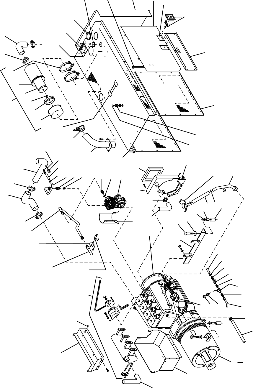
OM-166 941 Page 42
1
2
34
5
678
910
11
12
131415
16
17
18
19
20
29
30 31 32 33 34 35
10
28
Figure 11-1B. Main Assembly
36
37 38
40
39
68
46
49
50
51
52
55
61
62
63
64
65
66
67
56
57
Fig 11-5
47
48
53
54
58
17
18
21 22 10
23 24
25
27
41
42
43
44
45
5960
65
69
70
15
71
72
73
74
26
ST-800 491-B (2 of 2)

OM-166 941 Page 43
Part
No.
Dia.
Mkgs.
Figure 11-1B. Main Assembly (Continued)
Item
No. Description Quanti
ty
49 089 351 FITTING, pipe brs plug hexhd 1/2NPT 1. . . . . . . . . . . . . . . . . . . . . . . . . . . . . . . . . . . . . . . . . . . . . . . .
50 1532480009309 BAFFLE, lower air intake 1. . . . . . . . . . . . . . . . . . . . . . . . . . . . . . . . . . . . . . . . . . . . . . . . . . . .
51 1528480009309 BRACKET, oil neck w/cap 1. . . . . . . . . . . . . . . . . . . . . . . . . . . . . . . . . . . . . . . . . . . . . . . . . . .
52 1528520009309 PIPE, oil fill 1. . . . . . . . . . . . . . . . . . . . . . . . . . . . . . . . . . . . . . . . . . . . . . . . . . . . . . . . . . . . . . . .
53 071 890 RETAINER, mount eng/gen 4. . . . . . . . . . . . . . . . . . . . . . . . . . . . . . . . . . . . . . . . . . . . . . . . . . . . . . . . .
54 1529040009309 CLAMP, hose 1.500 2. . . . . . . . . . . . . . . . . . . . . . . . . . . . . . . . . . . . . . . . . . . . . . . . . . . . . . . . .
55 1528470009309 HOSE, oil filler 1. . . . . . . . . . . . . . . . . . . . . . . . . . . . . . . . . . . . . . . . . . . . . . . . . . . . . . . . . . . . .
56 071 730 TUBING, stl .875 OD x 12ga wall x 2.500 4. . . . . . . . . . . . . . . . . . . . . . . . . . . . . . . . . . . . . . . . . . . . .
57 602 246 WASHER, flat stl std .500 4. . . . . . . . . . . . . . . . . . . . . . . . . . . . . . . . . . . . . . . . . . . . . . . . . . . . . . . . . . .
58 071 731 WASHER, flat stl .656 ID x 2.250 OD 4. . . . . . . . . . . . . . . . . . . . . . . . . . . . . . . . . . . . . . . . . . . . . . . . .
59 601 945 SCREW, cap stl hexhd .625-18 x 4.000 4. . . . . . . . . . . . . . . . . . . . . . . . . . . . . . . . . . . . . . . . . . . . . . .
60 116 707 SUPPORT, front engine 1. . . . . . . . . . . . . . . . . . . . . . . . . . . . . . . . . . . . . . . . . . . . . . . . . . . . . . . . . . . .
61 603 110 HOSE, nprn .500 ID x .687 OD (order by ft) 2ft. . . . . . . . . . . . . . . . . . . . . . . . . . . . . . . . . . . . . . . . . . .
62 010 858 CLAMP, hose .500-.906clp dia 1. . . . . . . . . . . . . . . . . . . . . . . . . . . . . . . . . . . . . . . . . . . . . . . . . . . . . . .
63 0395990009309 FITTING, brs barbed M 1/2tbg x 1/2NPT 1. . . . . . . . . . . . . . . . . . . . . . . . . . . . . . . . . . . . . . .
64 088 684 VALVE, ball bronze 1/2thd female 1. . . . . . . . . . . . . . . . . . . . . . . . . . . . . . . . . . . . . . . . . . . . . . . . . . . .
65 1063940009309 FITTING, stl flrd conn M 1/2tbg x 1/2tbg 2. . . . . . . . . . . . . . . . . . . . . . . . . . . . . . . . . . . . . . .
66 1178270009309 FITTING, pipe stl tee F 1/2NPT 1. . . . . . . . . . . . . . . . . . . . . . . . . . . . . . . . . . . . . . . . . . . . . . .
67 1107430009309 FITTING, brs flrd conn M hd 1/4tbg x 1/8NPT 1. . . . . . . . . . . . . . . . . . . . . . . . . . . . . . . . . .
68 1355720009309 HOSE, oil 47.000 3/4 swivel both ends. . . . . . . . . . . . . . . . . (same as Item 29 Fig 11-3) 1. . . . . . . . . . . . . . . . . . . . . . . . . . . . . . . . .
69 118 452 FITTING, adapter oil drain 1. . . . . . . . . . . . . . . . . . . . . . . . . . . . . . . . . . . . . . . . . . . . . . . . . . . . . . . . . .
70 131 208 STOP, throttle 1. . . . . . . . . . . . . . . . . . . . . . . . . . . . . . . . . . . . . . . . . . . . . . . . . . . . . . . . . . . . . . . . . . . . .
71 1448100009309 HOSE, cooling compressor 1. . . . . . . . . . . . . . . . . . . . . . . . . . . . . . . . . . . . . . . . . . . . . . . . . .
72 Fig 11-5 GENERATOR 1. . . . . . . . . . . . . . . . . . . . . . . . . . . . . . . . . . . . . . . . . . . . . . . . . . . . . . . . . . . . . . . . . . . . .
73 1448640009309 BAFFLE, air lower 1. . . . . . . . . . . . . . . . . . . . . . . . . . . . . . . . . . . . . . . . . . . . . . . . . . . . . . . . . .
74 132 712 PIPE, muffler extension elb 1.875 OD 1. . . . . . . . . . . . . . . . . . . . . . . . . . . . . . . . . . . . . . . . . . . . . . . .
119 836 TUBING, stl .875 OD x .563 ID x .875 lg 2. . . . . . . . . . . . . . . . . . . . . . . . . . . . . . . . . . . . . . . . . . . . . . . . .
♦041 481 STARTING AID, diesel (consisting of) 1. . . . . . . . . . . . . . . . . . . . . . . . . . . . . . . . . . . . . . . . . . . . . . . . . .
ES1 ♦034 074 VALVE, ether (diesel starting aid) 1. . . . . . . . . . . . . . . . . . . . . . . . . . . . . . . . . . . . . . . . . . . . . . . . .
♦083 859 BRACKET, mtg fuel filter/quick start 1. . . . . . . . . . . . . . . . . . . . . . . . . . . . . . . . . . . . . . . . . . . . . . . . . . . .
♦195 754 ADAPTER, atomizer 1. . . . . . . . . . . . . . . . . . . . . . . . . . . . . . . . . . . . . . . . . . . . . . . . . . . . . . . . . . . . . . . . .
♦046 410 ATOMIZER, .125 L elbow orf 12 o’clock from inlet 1. . . . . . . . . . . . . . . . . . . . . . . . . . . . . . . . . . . . . . . .
♦035 325 LABEL, ether starting aid caution etc 1. . . . . . . . . . . . . . . . . . . . . . . . . . . . . . . . . . . . . . . . . . . . . . . . . . .
S8 ♦021 467 SWITCH, tgl SPST 3A 250V off-none-(on) spd term 1. . . . . . . . . . . . . . . . . . . . . . . . . . . . . . . . . .
♦021 385 BOOT, toggle switch lever 1. . . . . . . . . . . . . . . . . . . . . . . . . . . . . . . . . . . . . . . . . . . . . . . . . . . . . . . . . . . . .
♦020 185 FITTING, pipe brs elbow st 1/8NPT 1. . . . . . . . . . . . . . . . . . . . . . . . . . . . . . . . . . . . . . . . . . . . . . . . . . . .
+When ordering a component originally displaying a precautionary label, the label should also be ordered.
*Recommended Spare Parts.
♦OPTIONAL
BE SURE TO PROVIDE MODEL AND SERIAL NUMBER WHEN ORDERING REPLACEMENT PARTS.
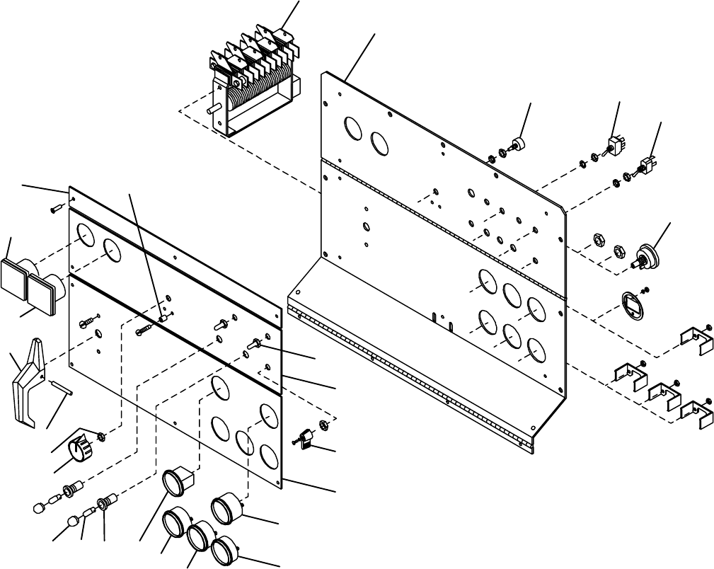
OM-166 941 Page 44
Figure 11-2. Panel, Front w/Components
1
2
5
6
7
8
9
10
11
12
13
14
9
15161718
19
20
21
ST-800 490-A
*Includes Item 4
4
3*
22
23
24 25

OM-166 941 Page 45
Description Quanti
ty
Part
No.
Dia.
Mkgs.
Figure 11-2. Panel, Front w/Components (Fig 11-1A Item 75)
Item
No.
1 S9 1346300009880 SWITCH, range 1. . . . . . . . . . . . . . . . . . . . . . . . . . . . . . . . . . . . . . . . . . . . . . . . . . . . . . . .
2 1183400010202 PANEL, front upper 1. . . . . . . . . . . . . . . . . . . . . . . . . . . . . . . . . . . . . . . . . . . . . . . . . . . . . . . . .
3 R1 072 462 POTENTIOMETER, w/shaft lock (consisting of) 1. . . . . . . . . . . . . . . . . . . . . . . . . . . . . . . . . . .
4 072 590 LOCK, shaft pot .375-32 x .250 1. . . . . . . . . . . . . . . . . . . . . . . . . . . . . . . . . . . . . . . . . . . . . . . . . . . . . .
5 S4 011 611 SWITCH, tgl DPDT 15A 125V 1. . . . . . . . . . . . . . . . . . . . . . . . . . . . . . . . . . . . . . . . . . . . . . . . . . .
6 S5 011 609 SWITCH, tgl SPDT 15A 125VAC 1. . . . . . . . . . . . . . . . . . . . . . . . . . . . . . . . . . . . . . . . . . . . . . . .
7 S1 172 070 SWITCH, ignition 5posn w/out handle 1. . . . . . . . . . . . . . . . . . . . . . . . . . . . . . . . . . . . . . . . . . . .
8 021 385 BOOT, tgl switch lever 2. . . . . . . . . . . . . . . . . . . . . . . . . . . . . . . . . . . . . . . . . . . . . . . . . . . . . . . . . . . . . .
9 PLATE, ident control rating (order by model and NSPR number) 1. . . . . . . . . . . . . . . . . . . . . . . . . . . . . . . . . .
10 125 707 LEVER, switch 1. . . . . . . . . . . . . . . . . . . . . . . . . . . . . . . . . . . . . . . . . . . . . . . . . . . . . . . . . . . . . . . . . . . .
11 FG 118 066 GAUGE, fuel elec 12V neg grd 1. . . . . . . . . . . . . . . . . . . . . . . . . . . . . . . . . . . . . . . . . . . . . . . . .
12 V2 164 747 METER, volt batt chg 8-18 scale 1. . . . . . . . . . . . . . . . . . . . . . . . . . . . . . . . . . . . . . . . . . . . . . . . .
13 OG 129 870 GAUGE, pressure oil 25-30PSI 1. . . . . . . . . . . . . . . . . . . . . . . . . . . . . . . . . . . . . . . . . . . . . . . . .
128 829 KIT, oil line 44.000 in 1/8NPT x 10mm 1. . . . . . . . . . . . . . . . . . . . . . . . . . . . . . . . . . . . . . . . . . . . . . . . . . .
14 1298370009309 GAUGE/SWITCH, temp oil mech 300deg setting 1. . . . . . . . . . . . . . . . . . . . . . . . . . . . . . .
15 HM 118 058 METER, hour 12-24VDC 1. . . . . . . . . . . . . . . . . . . . . . . . . . . . . . . . . . . . . . . . . . . . . . . . . . . . . .
16 082 788 HOLDER, light ind only 2. . . . . . . . . . . . . . . . . . . . . . . . . . . . . . . . . . . . . . . . . . . . . . . . . . . . . . . . . . . . .
17 PL1,3 *048 155 BULB, incand flg base 12V 2. . . . . . . . . . . . . . . . . . . . . . . . . . . . . . . . . . . . . . . . . . . . . . . . . .
18 082 789 LENS, light ind red 2. . . . . . . . . . . . . . . . . . . . . . . . . . . . . . . . . . . . . . . . . . . . . . . . . . . . . . . . . . . . . . . . .
19 097 926 KNOB, pointer 1. . . . . . . . . . . . . . . . . . . . . . . . . . . . . . . . . . . . . . . . . . . . . . . . . . . . . . . . . . . . . . . . . . . .
20 010 647 PIN, spring .156 x 1.250 1. . . . . . . . . . . . . . . . . . . . . . . . . . . . . . . . . . . . . . . . . . . . . . . . . . . . . . . . . . . .
21 090 231 HANDLE, switch range 1. . . . . . . . . . . . . . . . . . . . . . . . . . . . . . . . . . . . . . . . . . . . . . . . . . . . . . . . . . . . .
22 A2 164 875 METER, amp DC 50MV 0-1K scale 1. . . . . . . . . . . . . . . . . . . . . . . . . . . . . . . . . . . . . . . . . . . . . .
23 V1 164 872 METER, volt DC 0-100 scale 1. . . . . . . . . . . . . . . . . . . . . . . . . . . . . . . . . . . . . . . . . . . . . . . . . . . .
24 NAMEPLATE, (order by model and NSPR number) 1. . . . . . . . . . . . . . . . . . . . . . . . . . . . . . . . . . . . . . . . . . . . .
25 022 289 TUBING, stl .312 OD x .187 ID 2. . . . . . . . . . . . . . . . . . . . . . . . . . . . . . . . . . . . . . . . . . . . . . . . . . . . . .
*Recommended Spare Parts.
BE SURE TO PROVIDE MODEL AND SERIAL NUMBER WHEN ORDERING REPLACEMENT PARTS.
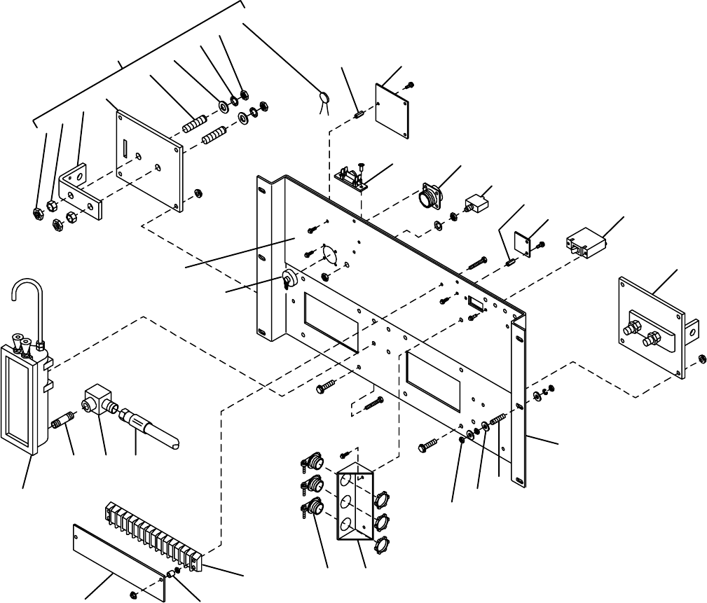
OM-166 941 Page 46
Figure 11-3. Panel, Lower Front w/Components
ST-147 320-F
1
2345
678
9
10 11
12
14
15 16
19
20
212223
2425
27
26
13
17
18
2
10
1
28 29
31
30

OM-166 941 Page 47
Description Quanti
ty
Part
No.
Dia.
Mkgs.
Figure 11-3. Panel, Lower Front w/Components
Item
No.
(Fig 11-1A Item 66)
1 0386120009309 TERMINAL ASSEMBLY, pwr output (consisting of) 2. . . . . . . . . . . . . . . . . . . . . . . . . . . . . .
2 601 840 NUT, brs hex .500-13 jam 4. . . . . . . . . . . . . . . . . . . . . . . . . . . . . . . . . . . . . . . . . . . . . . . . . . . . . . . . . . .
3 601 839 NUT, brs hex .500-13 full 2. . . . . . . . . . . . . . . . . . . . . . . . . . . . . . . . . . . . . . . . . . . . . . . . . . . . . . . . . . . .
4 038 847 BUS BAR, term pwr output 1. . . . . . . . . . . . . . . . . . . . . . . . . . . . . . . . . . . . . . . . . . . . . . . . . . . . . . . . . .
5 Neg/Pos 038 613 TERMINAL BOARD, pwr output 1. . . . . . . . . . . . . . . . . . . . . . . . . . . . . . . . . . . . . . . . . . . .
6 038 900 STUD, brs .500-13 x 2.250 2. . . . . . . . . . . . . . . . . . . . . . . . . . . . . . . . . . . . . . . . . . . . . . . . . . . . . . . . . .
7 602 247 WASHER, flat stl SAE .500 2. . . . . . . . . . . . . . . . . . . . . . . . . . . . . . . . . . . . . . . . . . . . . . . . . . . . . . . . . .
8 605 787 WASHER, lock stl intl tooth .500 2. . . . . . . . . . . . . . . . . . . . . . . . . . . . . . . . . . . . . . . . . . . . . . . . . . . . .
9 C1,2 085 321 CAPACITOR 1. . . . . . . . . . . . . . . . . . . . . . . . . . . . . . . . . . . . . . . . . . . . . . . . . . . . . . . . . . . . . . . .
601 976 SCREW, cap stl hexhd .500-13 x 1.500 (bus bar to terminal) 2. . . . . . . . . . . . . . . . . . . . . . . . . . . . . . .
044 942 NUT, locking .500-13 (bus bar to terminal) 2. . . . . . . . . . . . . . . . . . . . . . . . . . . . . . . . . . . . . . . . . . . . . . .
10 097 132 STAND-OFF, 6-32 x .375 lg 5. . . . . . . . . . . . . . . . . . . . . . . . . . . . . . . . . . . . . . . . . . . . . . . . . . . . . . . . .
11 PC3 150 415 CIRCUIT CARD, connector 1. . . . . . . . . . . . . . . . . . . . . . . . . . . . . . . . . . . . . . . . . . . . . . . . . . . .
PLG3-5 165 668 CONNECTOR & SOCKETS, (consisting of) 3. . . . . . . . . . . . . . . . . . . . . . . . . . . . . . . . . . . . .
079 534 CONNECTOR, circ skt push-in 14-18ga Amp 66358-6 10. . . . . . . . . . . . . . . . . . . . . . . . . . . . . . . . . . . . .
12 VR1/R4 046 819 SUPPRESSOR 1. . . . . . . . . . . . . . . . . . . . . . . . . . . . . . . . . . . . . . . . . . . . . . . . . . . . . . . . . .
13 RC3 085 302 CONNECTOR, circ 9skt rcpt Amphenol MS-3102A-20-16S 1. . . . . . . . . . . . . . . . . . . . . . . . .
14 CB3 083 432 CIRCUIT BREAKER, man reset 1P 10A 250V 1. . . . . . . . . . . . . . . . . . . . . . . . . . . . . . . . . . . .
15 PC4 152 966 CIRCUIT CARD, filter HF 1. . . . . . . . . . . . . . . . . . . . . . . . . . . . . . . . . . . . . . . . . . . . . . . . . . . . . .
16 CB1 1532470009309 CIRCUIT BREAKER, mag SPDT 30A 250VAC 1. . . . . . . . . . . . . . . . . . . . . . . . . . . .
17 1502670009309 PANEL, front lower 1. . . . . . . . . . . . . . . . . . . . . . . . . . . . . . . . . . . . . . . . . . . . . . . . . . . . . . . . .
18 083 030 STUD, brs grd .250-20 x 1.750 1. . . . . . . . . . . . . . . . . . . . . . . . . . . . . . . . . . . . . . . . . . . . . . . . . . . . . .
19 010 915 WASHER, flat brs .250 ID x .625 OD 5. . . . . . . . . . . . . . . . . . . . . . . . . . . . . . . . . . . . . . . . . . . . . . . . .
20 601 836 NUT, brs hex .250-20 3. . . . . . . . . . . . . . . . . . . . . . . . . . . . . . . . . . . . . . . . . . . . . . . . . . . . . . . . . . . . . .
21 0918600009309 STRAIN RELIEF 1. . . . . . . . . . . . . . . . . . . . . . . . . . . . . . . . . . . . . . . . . . . . . . . . . . . . . . . . . . .
22 010 916 CONNECTOR, clamp cable .750 3. . . . . . . . . . . . . . . . . . . . . . . . . . . . . . . . . . . . . . . . . . . . . . . . . . . .
23 3T 073 873 BLOCK, term 30A 14P 1. . . . . . . . . . . . . . . . . . . . . . . . . . . . . . . . . . . . . . . . . . . . . . . . . . . . . . . . .
24 022 289 TUBING, stl .312 OD x .187 ID x .437 lg 2. . . . . . . . . . . . . . . . . . . . . . . . . . . . . . . . . . . . . . . . . . . . . .
25 1482370009309 COVER, terminal 1. . . . . . . . . . . . . . . . . . . . . . . . . . . . . . . . . . . . . . . . . . . . . . . . . . . . . . . . . . .
26 1479080009309 GAUGE, oil level 1. . . . . . . . . . . . . . . . . . . . . . . . . . . . . . . . . . . . . . . . . . . . . . . . . . . . . . . . . . .
27 1224460009309 FITTING, pipe galv nipple .500NPT x 1.500 lg 1. . . . . . . . . . . . . . . . . . . . . . . . . . . . . . . . . .
28 0886900009309 FITTING, stl flrd elbow fem 1/2tbg x 1/2NPT 1. . . . . . . . . . . . . . . . . . . . . . . . . . . . . . . . . . .
29 1355720009309 HOSE, oil 47.000 3/4 swivel both ends. . . . . . . . . . . . . . . . . (same as Item 70 Fig 11-1B) 1. . . . . . . . . . . . . . . . . . . . . . . . . . . . . . . .
30 039 885 CONNECTOR, circ protective cap Amphenol 9760-20 1. . . . . . . . . . . . . . . . . . . . . . . . . . . . . . . . . .
31 PLATE, ident control rating lower. . . . . . . . . . . . . . . . . . . . . . . . . . . . . . . . . (order by model and NSPR number) 1. . . . . . . . . . . . . . . . . . . . . . . . .
1577780009309 STRAP, grounding (front panel to base) 1. . . . . . . . . . . . . . . . . . . . . . . . . . . . . . . . . . . . . . . . . . .
1577920009309 STRAP, grounding (front panel to control box) 1. . . . . . . . . . . . . . . . . . . . . . . . . . . . . . . . . . . . .
BE SURE TO PROVIDE MODEL AND SERIAL NUMBER WHEN ORDERING REPLACEMENT PARTS.
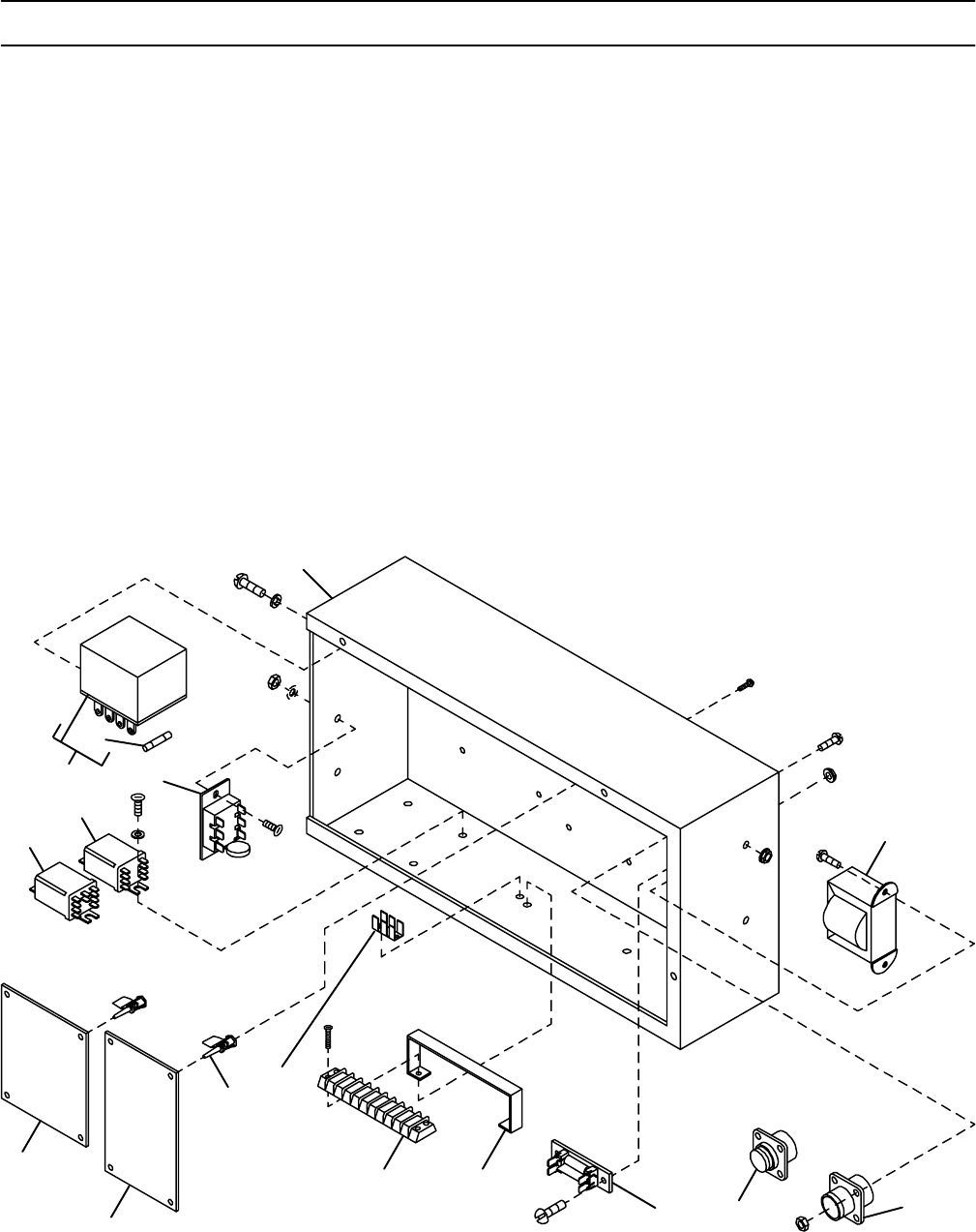
OM-166 941 Page 48
Description Quanti
ty
Part
No.
Dia.
Mkgs.
Figure 11-4. Control Box (Fig 11-1A Item 65)
Item
No.
1 1186380009309 ENCLOSURE, control box 1. . . . . . . . . . . . . . . . . . . . . . . . . . . . . . . . . . . . . . . . . . . . . . . . . . .
2 T1 0700700009309 TRANSFORMER, control 1. . . . . . . . . . . . . . . . . . . . . . . . . . . . . . . . . . . . . . . . . . . . . . . .
3 RC6 090 246 CONNECTOR w/PINS, (consisting of) 1. . . . . . . . . . . . . . . . . . . . . . . . . . . . . . . . . . . . . . . . . . .
079 535 CONNECTOR, circ pin push-in 14-18ga Amp 66359-6 16. . . . . . . . . . . . . . . . . . . . . . . . . . . . . . . . . . . . .
4 RC7 047 637 CONNECTOR & SOCKETS, (consisting of) 1. . . . . . . . . . . . . . . . . . . . . . . . . . . . . . . . . . . . . .
079 534 CONNECTOR, circ skt push-in 14-18ga Amp 66358-6 14. . . . . . . . . . . . . . . . . . . . . . . . . . . . . . . . . . . . .
5 D1 189 701 DIODE/CAPACITOR BOARD 1. . . . . . . . . . . . . . . . . . . . . . . . . . . . . . . . . . . . . . . . . . . . . . . . . . .
6 1562370009309 BRACKET, holding 1. . . . . . . . . . . . . . . . . . . . . . . . . . . . . . . . . . . . . . . . . . . . . . . . . . . . . . . . . .
7 1T 098 828 BLOCK, term, 10A 10P 1. . . . . . . . . . . . . . . . . . . . . . . . . . . . . . . . . . . . . . . . . . . . . . . . . . . . . . . . .
8 129 524 TERMINAL, frict .250 x .032 uninsul male 1. . . . . . . . . . . . . . . . . . . . . . . . . . . . . . . . . . . . . . . . . . . . .
9 110 375 STAND-OFF SUPPORT, PC card No. 6 screw 8. . . . . . . . . . . . . . . . . . . . . . . . . . . . . . . . . . . . . . . . .
10 PC2 160 888 CIRCUIT CARD, voltage regulator 1. . . . . . . . . . . . . . . . . . . . . . . . . . . . . . . . . . . . . . . . . . . . . .
PLG2 168 071 CONNECTOR & SOCKETS, (consisting of) 1. . . . . . . . . . . . . . . . . . . . . . . . . . . . . . . . . . . . . . .
114 066 CONNECTOR, rect skt 20-14ga Amp 350536-1 9. . . . . . . . . . . . . . . . . . . . . . . . . . . . . . . . . . . . . . . . . . .
11 PC1 1337570009309 CIRCUIT CARD, field current regulator 1. . . . . . . . . . . . . . . . . . . . . . . . . . . . . . . . . . .
PLG1 135 275 CONNECTOR & SOCKETS, (consisting of) 1. . . . . . . . . . . . . . . . . . . . . . . . . . . . . . . . . . . . . . .
114 066 CONNECTOR, rect skt 20-14ga Amp 350536-1 15. . . . . . . . . . . . . . . . . . . . . . . . . . . . . . . . . . . . . . . . . . .
12 CR1 044 588 RELAY, encl 12VDC 3PDT 1. . . . . . . . . . . . . . . . . . . . . . . . . . . . . . . . . . . . . . . . . . . . . . . . . . . . .
13 CR3 059 268 RELAY, encl 120VAC DPDT 1. . . . . . . . . . . . . . . . . . . . . . . . . . . . . . . . . . . . . . . . . . . . . . . . . . . .
14 SR2 097 353 DIODE/SCR, bridge intg 2SCR 3 diodes 1. . . . . . . . . . . . . . . . . . . . . . . . . . . . . . . . . . . . . . . . .
15 MS1 118 072 SWITCH, magnetic shutdown 12VDC (consisting of) 1. . . . . . . . . . . . . . . . . . . . . . . . . . . . . .
16 F *048 317 FUSE, mintr gl 14A 32V 1. . . . . . . . . . . . . . . . . . . . . . . . . . . . . . . . . . . . . . . . . . . . . . . . . . . . . . . .
045 852 CLIP, component .687dia mtg adh back 1. . . . . . . . . . . . . . . . . . . . . . . . . . . . . . . . . . . . . . . . . . . . . . . . . .
1
2
3
45
67
8
9
10
11
12
13
14
15
16
ST-800 489
Figure 11-4. Control Box
*Recommended Spare Parts.
BE SURE TO PROVIDE MODEL AND SERIAL NUMBER WHEN ORDERING REPLACEMENT PARTS.
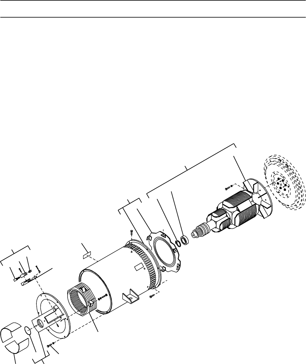
OM-166 941 Page 49
Description Quanti
ty
Part
No.
Figure 11-5. Generator (Fig 11-1B Item 72)
Item
No.
1 018 614 BRUSH SET, (consisting of) 3. . . . . . . . . . . . . . . . . . . . . . . . . . . . . . . . . . . . . . . . . . . . . . . . . . . . . . . . .
2 *151 299 BRUSH, contact 1. . . . . . . . . . . . . . . . . . . . . . . . . . . . . . . . . . . . . . . . . . . . . . . . . . . . . . . . . . . . . . . . . .
3 600 270 HOLDER, brush 1. . . . . . . . . . . . . . . . . . . . . . . . . . . . . . . . . . . . . . . . . . . . . . . . . . . . . . . . . . . . . . . . . . .
4 152 044 CAP, brush holder 1. . . . . . . . . . . . . . . . . . . . . . . . . . . . . . . . . . . . . . . . . . . . . . . . . . . . . . . . . . . . . . . . . .
5 049 650 BRACKET, mtg brushholder 1. . . . . . . . . . . . . . . . . . . . . . . . . . . . . . . . . . . . . . . . . . . . . . . . . . . . . . . . .
6 013 367 LABEL, warning moving parts can cause serious injury 2. . . . . . . . . . . . . . . . . . . . . . . . . . . . . . . . . .
7 +140 096 STATOR, generator (consisting of) 1. . . . . . . . . . . . . . . . . . . . . . . . . . . . . . . . . . . . . . . . . . . . . . . . . .
8 039 207 BAFFLE, air generator 1. . . . . . . . . . . . . . . . . . . . . . . . . . . . . . . . . . . . . . . . . . . . . . . . . . . . . . . . . . . . . .
9 083 751 ROTOR, gen (consisting of) 1. . . . . . . . . . . . . . . . . . . . . . . . . . . . . . . . . . . . . . . . . . . . . . . . . . . . . . . . .
10 024 617 RING, retaining external 1. . . . . . . . . . . . . . . . . . . . . . . . . . . . . . . . . . . . . . . . . . . . . . . . . . . . . . . . . . . . .
11 053 390 BEARING, ball 1. . . . . . . . . . . . . . . . . . . . . . . . . . . . . . . . . . . . . . . . . . . . . . . . . . . . . . . . . . . . . . . . . . . . .
12 083 748 FAN, rotor 1. . . . . . . . . . . . . . . . . . . . . . . . . . . . . . . . . . . . . . . . . . . . . . . . . . . . . . . . . . . . . . . . . . . . . . . . .
13 1450210009309 STATOR, exciter/endbell 1. . . . . . . . . . . . . . . . . . . . . . . . . . . . . . . . . . . . . . . . . . . . . . . . . . . . .
14 601 965 SCREW, .375-16 x 1.000hexhd 6. . . . . . . . . . . . . . . . . . . . . . . . . . . . . . . . . . . . . . . . . . . . . . . . . . . . . .
15 153 299 ENDBELL, generator (consisting of) 1. . . . . . . . . . . . . . . . . . . . . . . . . . . . . . . . . . . . . . . . . . . . . . . . . .
16 143 220 O-RING, 2.859 ID x .139CS 1. . . . . . . . . . . . . . . . . . . . . . . . . . . . . . . . . . . . . . . . . . . . . . . . . . . . . . . . .
17 004 203 STRIP, nyl .050 x 4.000 x 9.000 2. . . . . . . . . . . . . . . . . . . . . . . . . . . . . . . . . . . . . . . . . . . . . . . . . . . . . .
SD-134 503-C
234
6
8
9
10
12
15
11
16
1
7
17
14
13
5
Figure 11-5. Generator
*Recommended Spare Parts.
+When ordering a component originally displaying a precautionary label, the label should also be ordered.
BE SURE TO PROVIDE MODEL AND SERIAL NUMBER WHEN ORDERING REPLACEMENT PARTS.

Notes

