Miller Electric Syncrowave 250 Technical Manual ManualsLib Makes It Easy To Find Manuals Online!
2014-12-11
: Miller-Electric Miller-Electric-Syncrowave-250-Technical-Manual-120626 miller-electric-syncrowave-250-technical-manual-120626 miller-electric pdf
Open the PDF directly: View PDF ![]() .
.
Page Count: 84
Processes
TM-353E January 2001
Eff. w/Serial Number JJ339876
Description
TIG (GTAW) Welding
Stick (SMAW) Welding
Arc Welding Power Source
Syncrowave 250
60 Hz, 50 Hz
R
Visit our website at
www.MillerWelds.com

TABLE OF CONTENTS
1. Safety Precautions – Read Before Using 1. . . . . . . . . . . . . . . . . . . . . . . . . . . . . . . . . . . . . . . . . . . . . .
1.1 Symbol Usage 1. . . . . . . . . . . . . . . . . . . . . . . . . . . . . . . . . . . . . . . . . . . . . . . . . . . . . . . . . . . . . . . .
1.2 Servicing Hazards 1. . . . . . . . . . . . . . . . . . . . . . . . . . . . . . . . . . . . . . . . . . . . . . . . . . . . . . . . . . . . .
1.3 EMF Information 2. . . . . . . . . . . . . . . . . . . . . . . . . . . . . . . . . . . . . . . . . . . . . . . . . . . . . . . . . . . . . . .
SECTION 2 – DEFINITIONS 3. . . . . . . . . . . . . . . . . . . . . . . . . . . . . . . . . . . . . . . . . . . . . . . . . . . . . . . . . . . .
2-1. Warning Label Definitions 3. . . . . . . . . . . . . . . . . . . . . . . . . . . . . . . . . . . . . . . . . . . . . . . . . . . . . . .
2-2. Rating Label For CE Products 4. . . . . . . . . . . . . . . . . . . . . . . . . . . . . . . . . . . . . . . . . . . . . . . . . . .
2-3. Symbols And Definitions 5. . . . . . . . . . . . . . . . . . . . . . . . . . . . . . . . . . . . . . . . . . . . . . . . . . . . . . . .
SECTION 3 – INSTALLATION 6. . . . . . . . . . . . . . . . . . . . . . . . . . . . . . . . . . . . . . . . . . . . . . . . . . . . . . . . . . .
3-1. Specifications 6. . . . . . . . . . . . . . . . . . . . . . . . . . . . . . . . . . . . . . . . . . . . . . . . . . . . . . . . . . . . . . . . .
3-2. Volt-Ampere Curves 6. . . . . . . . . . . . . . . . . . . . . . . . . . . . . . . . . . . . . . . . . . . . . . . . . . . . . . . . . . . .
3-3. Duty Cycle And Overheating 7. . . . . . . . . . . . . . . . . . . . . . . . . . . . . . . . . . . . . . . . . . . . . . . . . . . . .
3-4. Selecting A Location 8. . . . . . . . . . . . . . . . . . . . . . . . . . . . . . . . . . . . . . . . . . . . . . . . . . . . . . . . . . . .
3-5. Dimensions And Weights 8. . . . . . . . . . . . . . . . . . . . . . . . . . . . . . . . . . . . . . . . . . . . . . . . . . . . . . . .
3-6. Tipping 9. . . . . . . . . . . . . . . . . . . . . . . . . . . . . . . . . . . . . . . . . . . . . . . . . . . . . . . . . . . . . . . . . . . . . . .
3-7. Weld Output Terminals And Selecting Cable Sizes 9. . . . . . . . . . . . . . . . . . . . . . . . . . . . . . . . . . .
3-8. Remote 14 Receptacle 10. . . . . . . . . . . . . . . . . . . . . . . . . . . . . . . . . . . . . . . . . . . . . . . . . . . . . . . . .
3-9. 115 Volts AC Duplex Receptacle And Shielding Gas Connections 10. . . . . . . . . . . . . . . . . . . . . .
3-10.Electrical Service Guide 11. . . . . . . . . . . . . . . . . . . . . . . . . . . . . . . . . . . . . . . . . . . . . . . . . . . . . . . . .
3-11.Placing Jumper Links And Connecting Input Power 12. . . . . . . . . . . . . . . . . . . . . . . . . . . . . . . . . .
SECTION 4 – OPERATION 13. . . . . . . . . . . . . . . . . . . . . . . . . . . . . . . . . . . . . . . . . . . . . . . . . . . . . . . . . . . . .
4-1. Controls 13. . . . . . . . . . . . . . . . . . . . . . . . . . . . . . . . . . . . . . . . . . . . . . . . . . . . . . . . . . . . . . . . . . . . . .
4-2. Output Selector Switch 14. . . . . . . . . . . . . . . . . . . . . . . . . . . . . . . . . . . . . . . . . . . . . . . . . . . . . . . . .
4-3. Meters 14. . . . . . . . . . . . . . . . . . . . . . . . . . . . . . . . . . . . . . . . . . . . . . . . . . . . . . . . . . . . . . . . . . . . . . .
4-4. Crater Time Controls 15. . . . . . . . . . . . . . . . . . . . . . . . . . . . . . . . . . . . . . . . . . . . . . . . . . . . . . . . . . .
4-5. Spot Time Controls 15. . . . . . . . . . . . . . . . . . . . . . . . . . . . . . . . . . . . . . . . . . . . . . . . . . . . . . . . . . . . .
4-6. AC Balance Control 16. . . . . . . . . . . . . . . . . . . . . . . . . . . . . . . . . . . . . . . . . . . . . . . . . . . . . . . . . . . .
4-7. Amperage Adjustment Controls 17. . . . . . . . . . . . . . . . . . . . . . . . . . . . . . . . . . . . . . . . . . . . . . . . . .
4-8. Output (Contactor) Control Switch 17. . . . . . . . . . . . . . . . . . . . . . . . . . . . . . . . . . . . . . . . . . . . . . . .
4-9. Arc Controls 18. . . . . . . . . . . . . . . . . . . . . . . . . . . . . . . . . . . . . . . . . . . . . . . . . . . . . . . . . . . . . . . . . .
4-10.Postflow Time Control 18. . . . . . . . . . . . . . . . . . . . . . . . . . . . . . . . . . . . . . . . . . . . . . . . . . . . . . . . . .
4-11.High Frequency Controls 19. . . . . . . . . . . . . . . . . . . . . . . . . . . . . . . . . . . . . . . . . . . . . . . . . . . . . . . .
4-12.Preflow Time Control (Optional) 19. . . . . . . . . . . . . . . . . . . . . . . . . . . . . . . . . . . . . . . . . . . . . . . . . .
SECTION 5 – THEORY OF OPERATION 20. . . . . . . . . . . . . . . . . . . . . . . . . . . . . . . . . . . . . . . . . . . . . . . . .
SECTION 6 – TROUBLESHOOTING 22. . . . . . . . . . . . . . . . . . . . . . . . . . . . . . . . . . . . . . . . . . . . . . . . . . . . .
6-1. Troubleshooting Table 22. . . . . . . . . . . . . . . . . . . . . . . . . . . . . . . . . . . . . . . . . . . . . . . . . . . . . . . . . .
6-2. Troubleshooting Circuit Diagram For Welding Power Source 26. . . . . . . . . . . . . . . . . . . . . . . . . .
6-3. Waveforms For Section 6-2 28. . . . . . . . . . . . . . . . . . . . . . . . . . . . . . . . . . . . . . . . . . . . . . . . . . . . . .
6-4. Control Board PC1 Testing Information (Use With Section 6-5) 30. . . . . . . . . . . . . . . . . . . . . . . .
6-5. Control Board PC1 Test Point Values 31. . . . . . . . . . . . . . . . . . . . . . . . . . . . . . . . . . . . . . . . . . . . . .
6-6. Remote Board PC2 Testing Information (Use With Section 6-7) 33. . . . . . . . . . . . . . . . . . . . . . . .
6-7. Remote 14 Filter Board PC2 Test Point Values (Use With Section 6-2 And Section 6-6) 34. . . .
6-8. Meter Calibration 35. . . . . . . . . . . . . . . . . . . . . . . . . . . . . . . . . . . . . . . . . . . . . . . . . . . . . . . . . . . . . .
6-9. Input Voltage Labels And Connections 36. . . . . . . . . . . . . . . . . . . . . . . . . . . . . . . . . . . . . . . . . . . . .
SECTION 7 – MAINTENANCE 37. . . . . . . . . . . . . . . . . . . . . . . . . . . . . . . . . . . . . . . . . . . . . . . . . . . . . . . . . .
7-1. Routine Maintenance 37. . . . . . . . . . . . . . . . . . . . . . . . . . . . . . . . . . . . . . . . . . . . . . . . . . . . . . . . . . .
7-2. Circuit Breaker CB1 37. . . . . . . . . . . . . . . . . . . . . . . . . . . . . . . . . . . . . . . . . . . . . . . . . . . . . . . . . . . .
7-3. Fuses F1 And F2 38. . . . . . . . . . . . . . . . . . . . . . . . . . . . . . . . . . . . . . . . . . . . . . . . . . . . . . . . . . . . . .
7-4. Adjusting Spark Gaps 38. . . . . . . . . . . . . . . . . . . . . . . . . . . . . . . . . . . . . . . . . . . . . . . . . . . . . . . . . .
SECTION 8 – HIGH FREQUENCY (HF) 39. . . . . . . . . . . . . . . . . . . . . . . . . . . . . . . . . . . . . . . . . . . . . . . . . . .
8-1. Welding Processes Using HF 39. . . . . . . . . . . . . . . . . . . . . . . . . . . . . . . . . . . . . . . . . . . . . . . . . . . .
8-2. Sources Of HF Radiation From Incorrect Installation 39. . . . . . . . . . . . . . . . . . . . . . . . . . . . . . . . .
8-3. Correct Installation 40. . . . . . . . . . . . . . . . . . . . . . . . . . . . . . . . . . . . . . . . . . . . . . . . . . . . . . . . . . . . .
SECTION 9 – ELECTRICAL DIAGRAMS 41. . . . . . . . . . . . . . . . . . . . . . . . . . . . . . . . . . . . . . . . . . . . . . . . .
SECTION 10 – PARTS LIST 68. . . . . . . . . . . . . . . . . . . . . . . . . . . . . . . . . . . . . . . . . . . . . . . . . . . . . . . . . . . .
TM-353D

dec_con1 10/95
Declaration of Conformity For
European Community (CE) Products
This information is provided for units with CE certification (see rating label on unit.)
NOTE
Manufacturer’s Name: Miller Electric Mfg. Co.
Manufacturer’s Address: 1635 W. Spencer Street
Appleton, WI 54914 USA
Declares that the product: Syncrowave250
conforms to the following Directives and Standards:
Directives
Low Voltage Directive: 73/23/EEC
Machinery Directives: 89/392/EEC, 91/368/EEC, 93/C 133/04, 93/68/EEC
Electromagnetic Capability Directives: 89/336, 92/31/EEC
Standards
Safety Requirements for Arc Welding Equipment part 1: EN 60974-1: 1990
Arc Welding Equipment Part 1: Welding Power Sources: IEC 974-1
(April 1995 – Draft revision)
Degrees of Protection provided by Enclosures (IP code): IEC 529: 1989
Insulation coordination for equipment within low-voltage systems:
Part 1: Principles, requirements and tests: IEC 664-1: 1992
Electromagnetic compatibility (EMC) Product standard for arc welding equipment:
EN50199: August 1995
European Contact: Mr. Luigi Vacchini, Managing Director
MILLER Europe S.P.A.
Via Privata Iseo
20098 San Giuliano
Milanese, Italy
Telephone: 39(02)98290-1
Fax: 39(02)98281-552

TM-353 Page 1Syncrowave 250
SECTION 1 – SAFETY PRECAUTIONS FOR SERVICING
safety_stm1 4/95
1-1. Symbol Usage
Means Warning! Watch Out! There are possible hazards with this
procedure! The possible hazards are shown in the adjoining symbols.
This group of symbols means Warning! Watch Out! possible ELECTRIC SHOCK, MOVING PARTS,
and HOT PARTS hazards. Consult symbols and related instructions below for necessary actions to
avoid the hazards.
YMarks a special safety message.
.Means NOTE; not safety related.
1-2. Servicing Hazards
ELECTRIC SHOCK can kill.
1. Do not touch live electrical parts.
2. Stop engine or turn OFF welding power source and
wire feeder, and disconnect and lockout input
power using line disconnect switch, circuit
breakers, or by removing plug from receptacle
before servicing unless the procedure specifically
requires an energized unit.
3. Insulate yourself from ground by standing or
working on dry insulating mats big enough to
prevent contact with the ground.
4. Do not leave live unit unattended.
5. When testing a live unit, use the one-hand method.
Do not put both hands inside unit. Keep one hand
free.
6. Disconnect input power conductors from
deenergized supply line BEFORE moving a
welding power source.
SIGNIFICANT DC VOLTAGE exists after
removal of input power on inverters.
7. Turn Off inverter, disconnect input power, and
discharge input capacitors according to
instructions in Maintenance Section before
touching any parts.
STATIC ELECTRICITY can damage
parts on circuit boards.
1. Put on grounded wrist strap BEFORE handling
boards or parts.
2. Use proper static-proof bags to store, move, or ship
PC boards.
FIRE OR EXPLOSION can result from
placing unit on, over, or near
combustible surfaces.
1. Do not place unit on, over, or near combustible
surfaces.
2. Do not service unit near flammables.
FLYING PIECES OF METAL or DIRT can
injure eyes.
1. Wear safety glasses with side shields or face shield
during servicing.
2. Be careful not to short metal tools, parts, or wires
together during testing and servicing.
HOT PARTS can cause severe burns.
1. Do not touch hot parts bare handed.
2. Allow cooling period before servicing welding gun
or torch.
EXPLODING PARTS can cause injury.
1. Failed parts can explode or cause other parts to
explode when power is applied to inverters.
2. Always wear a face shield and long sleeves when
servicing inverters.
ELECTRIC SHOCK HAZARD from
incorrect use of test equipment.
1. Turn Off welding power source and wire feeder or
stop engine before making or changing meter lead
connections.
2. At least one meter lead should be a self-retaining
spring clip such as an alligator clamp.
3. Read instructions for test equipment.
HIGH-FREQUENCY RADIATION can
interfere with radio navigation, safety
services, computers, and
communications equipment.
1. Have only qualified persons familiar with electronic
equipment perform this installation.
2. The user is responsible for having a qualified
electrician promptly correct any interference
problem resulting from the installation.
3. If notified by the FCC about interference, stop using
the equipment at once.
4. Have the installation regularly checked and
maintained.
5. Keep high-frequency source doors and panels
tightly shut, keep spark gaps at correct setting, and
use grounding and shielding to minimize the
possibility of interference.
The symbols shown below are used throughout this manual to call attention to and identify possible
hazards. When you see the symbol, watch out, and follow the related instructions to avoid the hazard.
Only qualified persons should service, test, maintain, and repair this unit.
During servicing, keep everybody, especially children, away.
WARNING
TM-353 Page 2 Syncrowave 250
FALLING EQUIPMENT can cause
serious personal injury and equipment
damage.
1. Use lifting eye to lift unit only, NOT running gear,
gas cylinders, or any other accessories.
2. Use equipment of adequate capacity to lift unit.
MAGNETIC FIELDS FROM HIGH
CURRENTS can affect pacemaker
operation.
1. Pacemaker wearers keep away from servicing
areas until consulting your doctor.
MOVING PARTS can cause injury.
1. Keep away from moving parts such as fans.
2. Keep all doors, panels, covers, and guards closed
and securely in place.
MOVING PARTS can cause injury.
1. Keep away from moving parts.
2. Keep away from pinch points such as drive rolls.
OVERUSE can cause OVERHEATED
EQUIPMENT.
1. Allow cooling period.
2. Reduce current or reduce duty cycle before
starting to weld again.
3. Follow rated duty cycle.
READ INSTRUCTIONS.
1. Use MILLER Testing Booklet (Part No. 150 853)
when servicing this unit.
2. Consult the Owner’s Manual for welding safety
precautions.
3. Use only genuine MILLER replacement parts.
1-3. EMF Information
Considerations About Welding And The Effects Of Low Frequency
Electric And Magnetic Fields
The following is a quotation from the General Conclusions Section of
the U.S. Congress, Office of Technology Assessment, Biological
Effects of Power Frequency Electric & Magnetic Fields – Background
Paper, OTA-BP-E-53 (Washington, DC: U.S. Government Printing
Office, May 1989): “. . . there is now a very large volume of scientific
findings based on experiments at the cellular level and from studies
with animals and people which clearly establish that low frequency
magnetic fields can interact with, and produce changes in, biological
systems. While most of this work is of very high quality, the results are
complex. Current scientific understanding does not yet allow us to
interpret the evidence in a single coherent framework. Even more
frustrating, it does not yet allow us to draw definite conclusions about
questions of possible risk or to offer clear science-based advice on
strategies to minimize or avoid potential risks.”
To reduce magnetic fields in the workplace, use the following
procedures:
1. Keep cables close together by twisting or taping them.
2. Arrange cables to one side and away from the operator.
3. Do not coil or drape cables around the body.
4. Keep welding power source and cables as far away as
practical.
5. Connect work clamp to workpiece as close to the weld as
possible.
About Pacemakers:
The above procedures are also recommended for pacemaker
wearers. Consult your doctor for complete information.
TM-353 Page 3Syncrowave 250
SECTION 2 – DEFINITIONS
2-1. Warning Label Definitions
S-176 254-A
1 1.1 1.2 1.3
3 3.1 3.2 3.3
4 4.1
+
22.1 2.2
+
+
5 6
+
2.3
Warning! Watch Out! There are
possible hazards as shown by the
symbols.
1 Electric shock from welding
electrode or wiring can kill.
1.1 Wear dry insulating gloves.
Do not touch electrode with
bare hand. Do not wear wet or
damaged gloves.
1.2 Protect yourself from electric
shock by insulating yourself
from work and ground.
1.3 Disconnect input plug or
power before working on
machine.
2 Breathing welding fumes can
be hazardous to your health.
2.1 Keep your head out of the
fumes.
2.2 Use forced ventilation or local
exhaust to remove the fumes.
2.3 Use ventilating fan to remove
fumes.
3 Welding sparks can cause
explosion or fire.
3.1 Keep flammables away from
welding. Don’t weld near
flammables.
3.2 Welding sparks can cause
fires. Have a fire extinguisher
nearby and have a watch
person ready to use it.
3.3 Do not weld on drums or any
closed containers.
4 Arc rays can burn eyes and
injure skin.
4.1 Wear hat and safety glasses.
Use ear protection and button
shirt collar. Use welding
helmet with correct shade of
filter. Wear complete body
protection.
5 Become trained and read the
instructions before working on
the machine or welding.
6 Do not remove or paint over
(cover) the label.
TM-353 Page 4 Syncrowave 250
2-2. Rating Label For CE Products
S-178 813-A
ISO/IEC 974-1
X 25% 60% 100%
7A/10.2V 310A/22.4V
U0 = 80V I2310A 200A 155A
U222.4V 18V 16.2V
X 25% 60% 100%
5A/20.2V 310A/32.4V
U0 = 80V I2310A 200A 155A
U232.4V 28V 26.2V
IP 21S
U1 = 220 I1max = 117.2A I1Eff = 59A
1
11
50 Hz
U1 = 380 I1max = 72.2A I1Eff = 36A
U1 = 415 I1max = 63.8A I1Eff = 32A
TM-353 Page 5Syncrowave 250
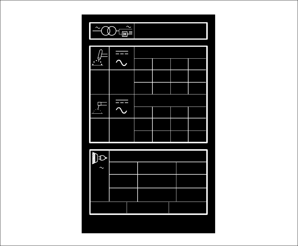
2-3. Symbols And Definitions
Some symbols are found only on CE products.
NOTE
AAmperes Panel–Local Gas Tungsten Arc
Welding (GTAW) Shielded Metal Arc
Welding (SMAW)
VVolts Do Not Switch
While Welding Arc Force (DIG) Spot Timer
Output Circuit Breaker Remote Temperature
Protective Earth
(Ground) Alternating Current High Frequency -
Start Input
Postflow Timer Preflow Timer High Frequency -
Continuous High Frequency
Gas (Supply) Gas Input Gas Output Increase/Decrease
Of Quantity
On Off Percent Direct Current
Balance Control Maximum Cleaning Maximum
Penetration Electrode Positive
Electrode
Negative Crater Time Meter Single-Phase
U0Rated No Load
Voltage (Average) U1Primary Voltage U2Conventional Load
Voltage Line Connection
I1Primary Current I2Rated Welding
Current XDuty Cycle 11Single-Phase
Combined AC/DC
Power Source
IP Degree Of
Protection I1eff Maximum Effective
Supply Current I1max Rated Maximum
Supply Current Hz Hertz
Electrode Work Thickness Gauge Spark Gap
SSeconds
TM-353 Page 6 Syncrowave 250
SECTION 3 – INSTALLATION
3-1. Specifications
Amperes Input at AC Balanced
Rated Load Output,
50/60 Hz, Single-Phase
Rated
Welding Output PFC** 200 V 230 V 460 V 575 V KVA KW Amp
Range Max
OCV IP
Rating
NEMA Class II
(40) – 250 No
PFC 106
(4.6*) 92
(4*) 46
(2*) 37
(1.6*) 21
(0.89*) 11.4
(0.68*)
Amperes, 30 Volts
AC, 40% Duty
Cycle
With
PFC 76 66 33 26 15.2 11.4
5–310 A 80 V 21
*While idling
**Power Factor Correction
Rated
Amperes Input at AC Balanced
Rated Load Output,
50/60 Hz, Single-Phase
Rated
Welding
Output PFC
** 200
V220
V230
V260
V380
V415
V460
V520
V575
VKVA KW Amp
Range Max
OCV IP
Rating
NEMA
Class I
(60) – 200
No
PFC 85
(4.6*) 77
(4.2*) 74
(4*) 65
(3.5*) 45
(2.4*) 41
(2.2*) 37
(2*) 33
(1.8*) 30
(1.6*) 17
(0.9*) 8.3
(0.7*)
Amperes,
28 Volts
AC, 60%
Duty Cycle
With
PFC 55
(57*) 64
(51*) 48
(49*) 48
(49*) 37
(30*) 34
(27*) 24
(25*) 48
(49*) 19
(20*) 11
(11*) 8.3
(0.6*)
5–310 A 80 V 21
*While idling
**Power Factor Correction
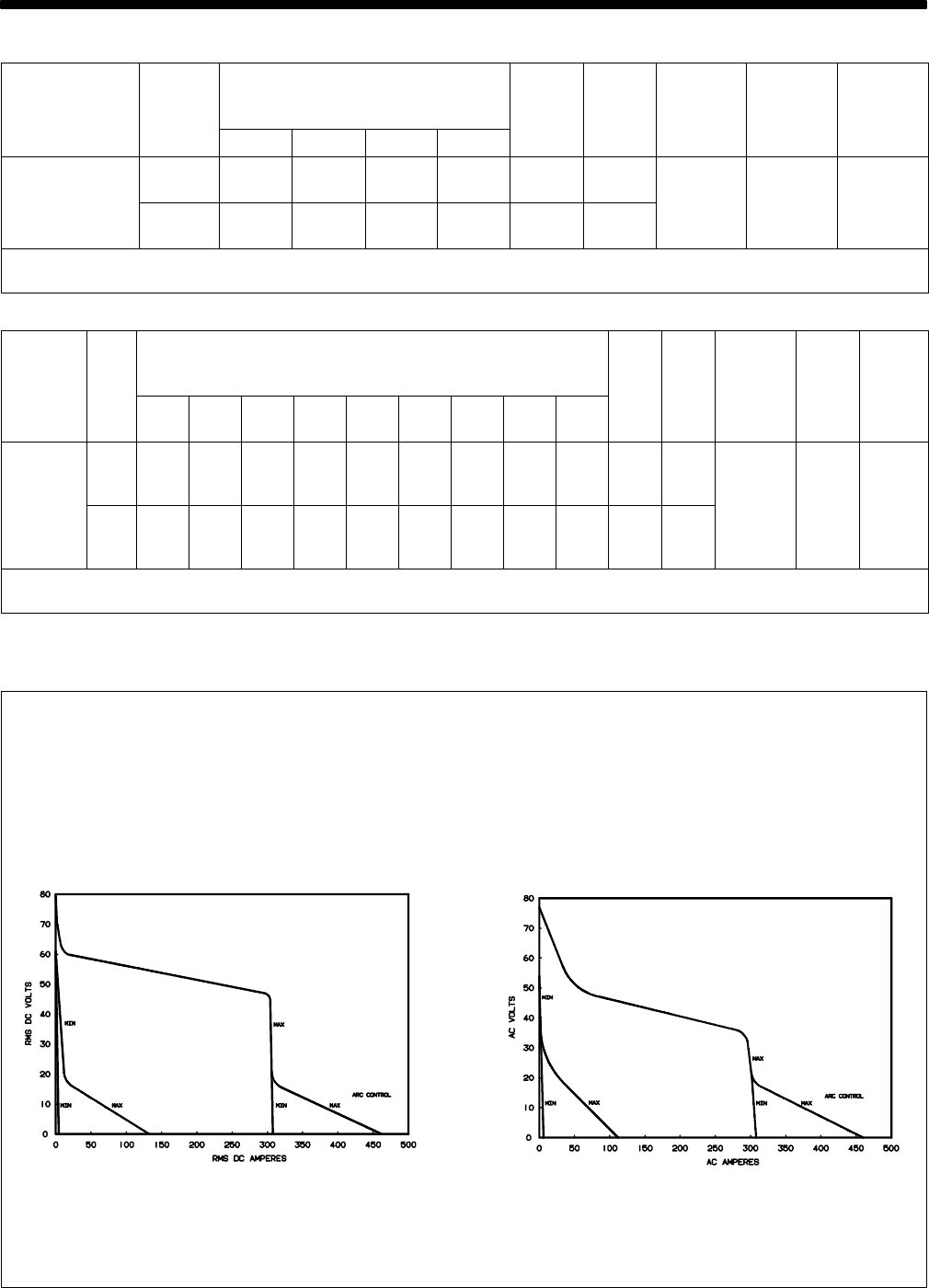
3-2. Volt-Ampere Curves
The volt-ampere curves show the
minimum and maximum voltage
and amperage output capabilities of
the welding power source. Curves
of other settings fall between the
curves shown.
ssb1.1 10/91 – SB-116 199 / SB-116 200
A. DC Mode B. AC Mode
TM-353 Page 7Syncrowave 250
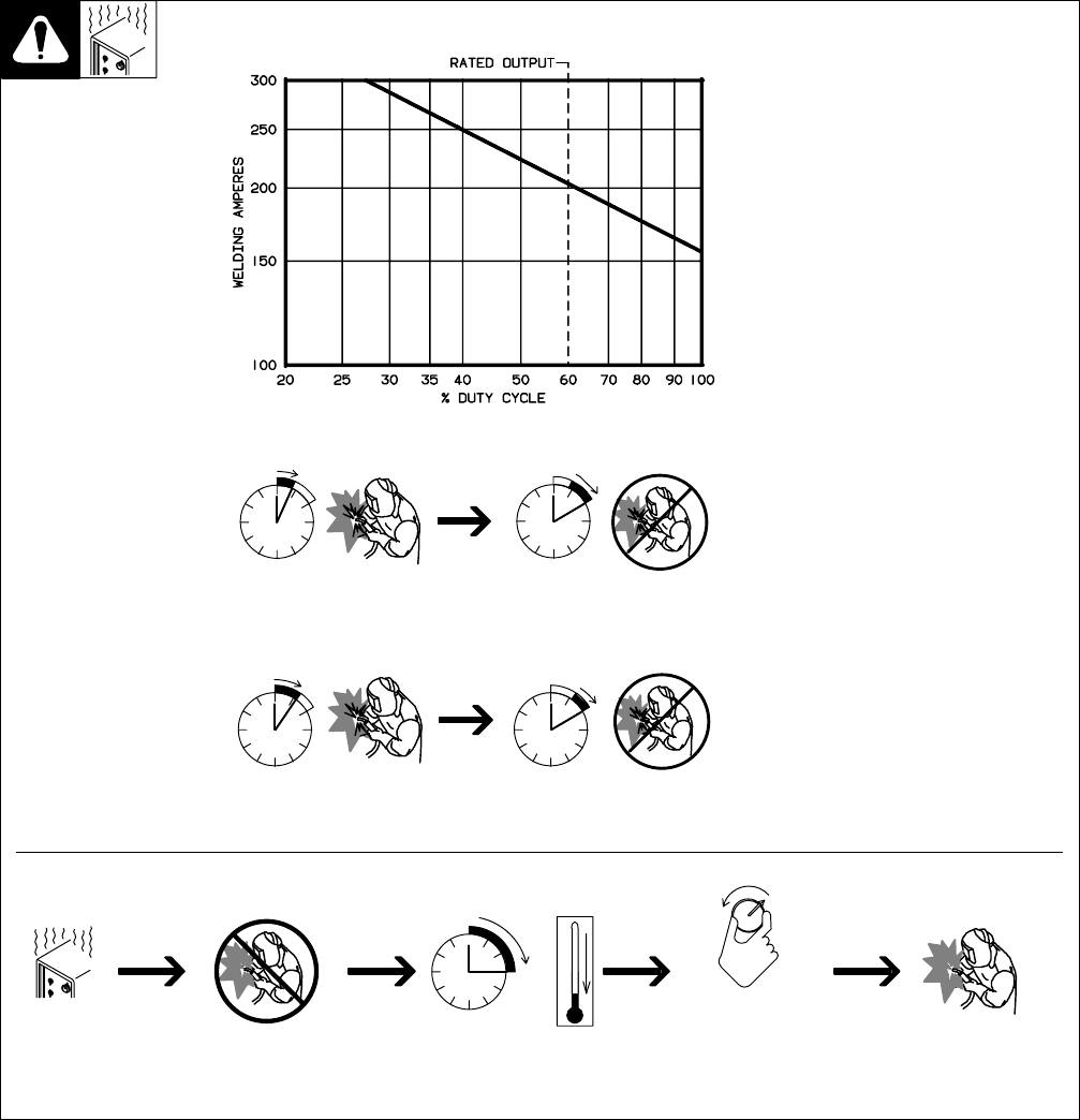
3-3. Duty Cycle And Overheating
4 Minutes Welding 6 Minutes Resting
6 Minutes Welding 4 Minutes Resting
Duty Cycle is percentage of 10 min-
utes that unit can weld at rated load
without overheating.
If unit overheats, thermostat opens,
output stops, light goes on (CE
models only), and cooling fan runs.
Wait fifteen minutes for unit to cool.
Reduce amperage or duty cycle be-
fore welding.
YExceeding duty cycle can
damage unit and void
warranty.
40% Duty Cycle At 250 Amperes (60 Hz Models Only)
Overheating
0
15
A
OR
Reduce Duty Cycle
Minutes
duty1 4/95 / SB-116 198
60% Duty Cycle At 200 Amperes
TM-353 Page 8 Syncrowave 250
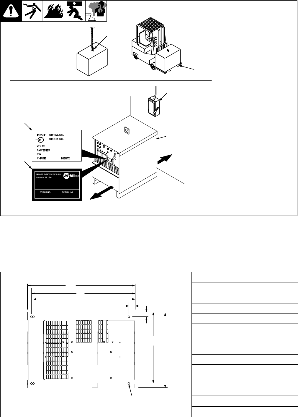
3-4. Selecting A Location
1 Lifting Eye
2 Lifting Forks
Use lifting eye or lifting forks to
move unit.
If using lifting forks, extend forks
beyond opposite side of unit.
3 Rating Label (Non CE Models
Only)
4 Rating Label (CE Models
Only, See Section 2-2)
Use rating label to determine input
power needs. CE label located on
rear panel.
5 Plate Label (CE Models Only)
6 Line Disconnect Device
Locate unit near correct input pow-
er supply.
YSpecial installation may be
required where gasoline or
volatile liquids are present –
see NEC Article 511 or CEC
Section 20.
1
2
Movement
ST-800 402 / ST-117 264-F
6
18 in (460
mm)
Location And Airflow
OR
18 in (460
mm)
3
5
4
3-5. Dimensions And Weights
Dimensions
AHeight 30-3/4 in (781 mm)
BCWidth 19-3/4 in (502 mm)
E
DLength 27-1/2 in (698 mm)
A27 in (686 mm)
B26 in (661 mm)
FC25-1/4 in (642 mm)
F
Front D1-1/2 in (38 mm)
GE 1-1/8 (29 mm)
F 17-7/8 (454 mm)
G 19-1/4 (489 mm)
H1/2 in (13 mm) Dia
6 Holes
HWeight
ST-154 792-B
355 lbs (161 kg)
TM-353 Page 9Syncrowave 250
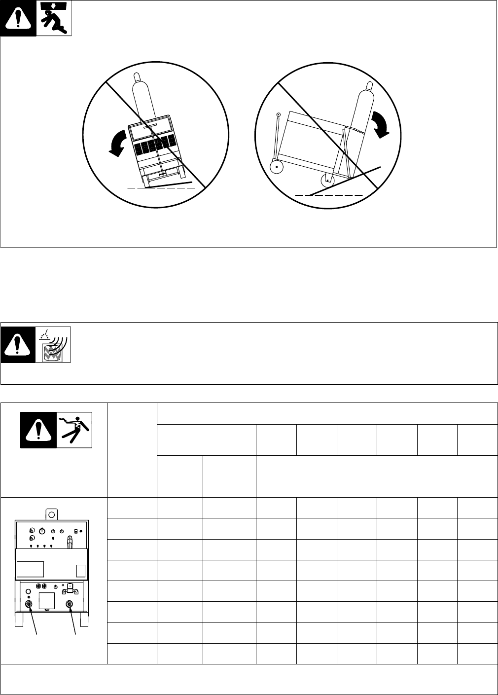
3-6. Tipping
YBe careful when placing or
moving unit over uneven
surfaces.
3-7. Weld Output Terminals And Selecting Cable Sizes
YARC WELDING can cause Electromagnetic Interference.
To reduce possible interference, keep weld cables as short as possible, close together, and down low, such as on the floor.
Locate welding operation 100 meters from any sensitive electronic equipment. Be sure this welding machine is installed
and grounded according to this manual. If interference still occurs, the user must take extra measures such as moving
the welding machine, using shielded cables, using line filters, or shielding the work area.
Total Cable (Copper) Length In Weld Circuit Not Exceeding
100 ft (30 m) Or Less 150 ft
(45 m) 200 ft
(60 m) 250 ft
(70 m) 300 ft
(90 m) 350 ft
(105 m) 400 ft
(120 m)
Weld Output
Terminals Welding
Amperes
10 – 60%
Duty
Cycle
60 – 100%
Duty
Cycle 10 – 100% Duty Cycle
100 4 4 4 3 2 1 1/0 1/0
150 3 3 2 1 1/0 2/0 3/0 3/0
200 3 2 1 1/0 2/0 3/0 4/0 4/0
250 2 1 1/0 2/0 3/0 4/0 2-2/0 2-2/0
300 1 1/0 2/0 3/0 4/0 2-2/0 2-3/0 2-3/0
350 1/0 2/0 3/0 4/0 2-2/0 2-3/0 2-3/0 2-4/0
400 1/0 2/0 3/0 4/0 2-2/0 2-3/0 2-4/0 2-4/0
ElectrodeWork
ST-154 795-C 500 2/0 3/0 4/0 2-2/0 2-3/0 2-4/0 3-3/0 3-3/0
Weld cable size (AWG) is based on either a 4 volts or less drop or a current density of at least 300 circular mils per ampere. Contact your dis-
tributor for the mm2 equivalent weld cable sizes. S-0007-E
TM-353 Page 10 Syncrowave 250
3-8. Remote 14 Receptacle
Socket* Socket Information
A24 volts ac.
BContact closure to A completes 24 volts ac contactor control
circuit.
CCommand reference; 0 to +10 volts dc output to remote control.
AJ
BKIDRemote control circuit common.
CLNH
DMG
F
AE0 to +10 volts dc input command signal from remote control.
EF
ST-154 795-C K Chassis common.
*The remaining sockets are not used.
3-9. 115 Volts AC Duplex Receptacle And Shielding Gas Connections
Ref. ST-154 795-C / Ref. ST-157 858
YTurn Off power before
connecting to receptacle.
1 115 V AC Receptacle
Receptacle is protected from over-
load by circuit breaker CB1 (see
Section 7-2).
2 Gas Valve In Fitting
3 Gas Valve Out Fitting
Fittings have 5/8-18 right-hand
threads
4 Cylinder Valve
Open valve slightly so gas flow
blows dirt from valve. Close valve.
5 Regulator/Flow Gauge
6 Flow Adjust
Typical flow rate is 20 cfh (cubic feet
per hour) (9.4 L/min)
7 High Frequency Control (see
Section 4-1)
4
5
6
1 7
3 2
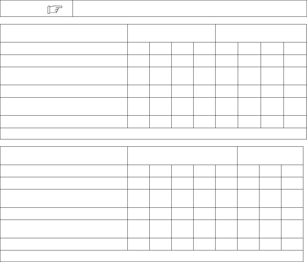
TM-353 Page 11Syncrowave 250
3-10. Electrical Service Guide
All values calculated at 60% duty cycle.
NOTE
60 Hertz Models Without Power Factor
Correction With Power Factor Correction
Input Voltage 200 230 460 575 200 230 460 575
Input Amperes At Rated Output 85 74 37 30 55 48 24 19
Max Recommended Standard Fuse Or Circuit
Breaker Rating In Amperes 125 110 60 45 80 70 35 30
Min Input Conductor Size In AWG/Kcmil 4 6 10 10 8 8 12 14
Max Recommended Input Conductor Length
In Feet (Meters) 173
(53) 158
(48) 291
(89) 455
(139) 86
(26) 114
(35) 186
(58) 189
(48)
Min Grounding Conductor Size In AWG/Kcmil 6 6 10 10 8 8 12 14
Reference: 1996 National Electrical Code (NEC) S-0092-J
50 Hertz Models Without Power Factor Correction With Power Factor
Correction
Input Voltage 220 260 380 415 520 220 380 415
Input Amperes At Rated Output 77 65 45 41 33 64 37 34
Max Recommended Standard Fuse Or Circuit
Breaker Rating In Amperes 125 100 70 60 50 90 60 50
Min Input Conductor Size In AWG/Kcmil 6 6 8 8 10 6 10 10
Max Recommended Input Conductor Length
In Feet (Meters) 145
(44) 202
(62) 291
(89) 347
(106) 372
(113) 145
(44) 291
(89) 347
(106)
Min Grounding Conductor Size In AWG/Kcmil 6 8 8 10 10 6 8 10
Reference: 1996 National Electrical Code (NEC) S-0092-J
TM-353 Page 12 Syncrowave 250
1
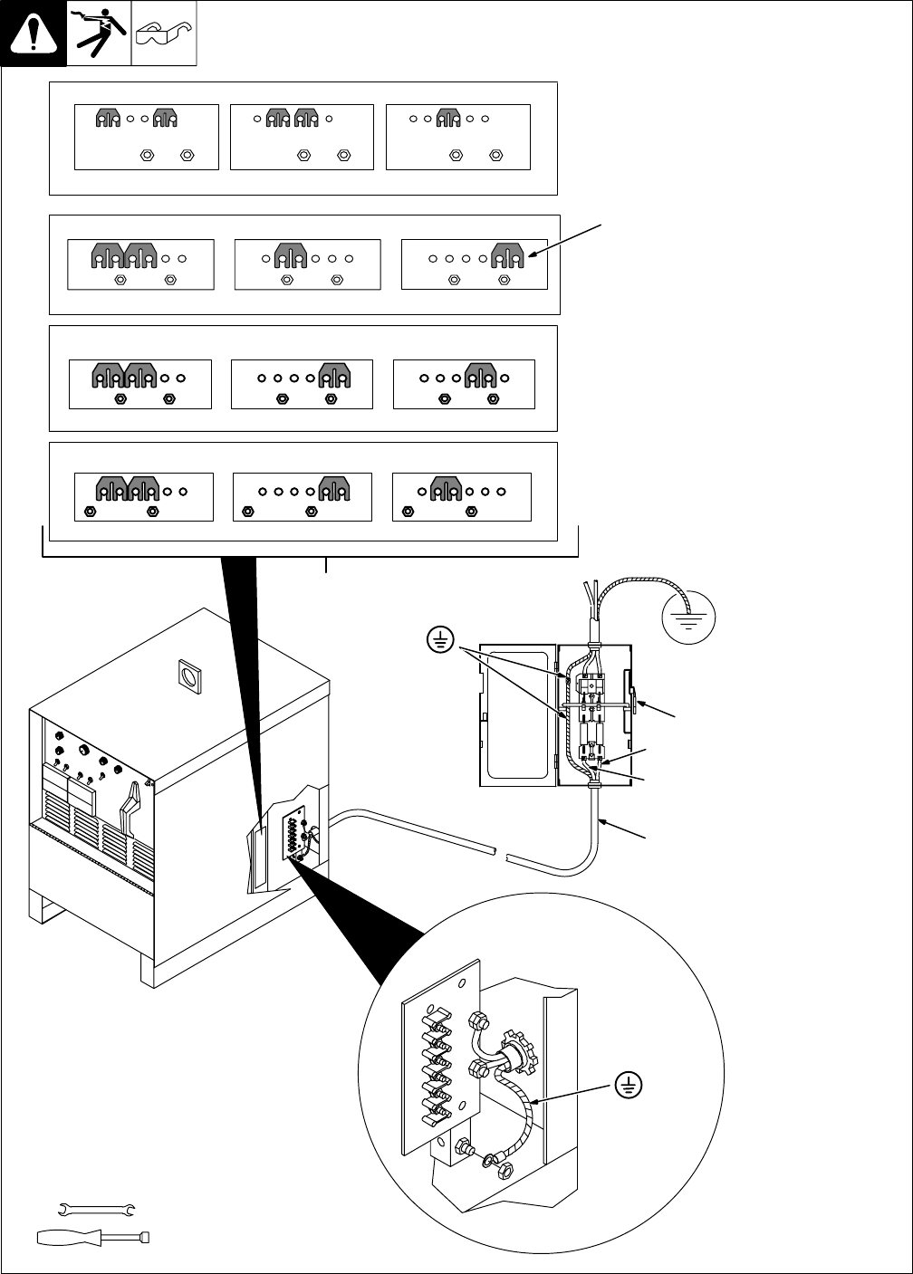
3-11. Placing Jumper Links And Connecting Input Power
ST-117 263-K
Check input voltage available at
site.
1 Jumper Link Label
Check label inside your unit–
only one label is on unit.
YOnly make connections for
the voltages shown on the la-
bel inside your unit. Do not
make connections for any
other voltages. If jumper link
label is missing from inside
unit, check rating label (see
Section 3-4) for allowable in-
put voltages.
2 Jumper Links
Move jumper links to match input
voltage.
3 Input And Grounding
Conductors
Select size and length using
Section 3-10.
4 Line Disconnect Device
Select type and size of overcurrent
protection using Section 3-10.
Reinstall side panel.
YSpecial installation may be
required where gasoline or
volatile liquids are present –
see NEC Article 511 or CEC
Section 20.
3/8 in
3/8, 1/2, 7/16 in
Tools Needed:
230 VOLTS
LL
460 VOLTS
LL
S-010 587-B
575 VOLTS
LL
230 VOLTS 460 VOLTS200 VOLTS
LL LL LL
S-083 566-C
2
L1 (U)
L2 (V)
GND/PE
Earth Ground
4
3
220 VOLTS
LL
380 VOLTS
LL
S-131 783-A
415 VOLTS
LL
Connect GND/PE
Conductor First
Connect GND/PE
Conductor First
S-047 672-A
260 VOLTS
LL
380 VOLTS
LL
520 VOLTS
LL
TM-353 Page 13Syncrowave 250
SECTION 4 – OPERATION
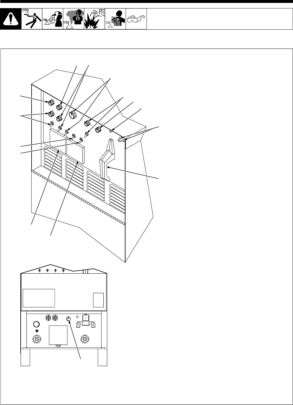
4-1. Controls
Ref. ST-117 264-F / Ref. ST-154 795-C
15
14
13
12
11
10
9
87
6
5
4
3
2
1
1 Ammeter
See Section 4-3.
2 Voltmeter
See Section 4-3.
3 High Frequency Switch
See Section 4-11.
4 Output (Contactor) Switch
See Section 4-8.
5 Spot Time Switch And Control
(Optional)
See Section 4-5.
6 Preflow Time Control (Optional)
See Section 4-12.
7 AC Balance Control
See Section 4-6.
8 Crater Time Control And Switch
See Section 4-4.
9 Amperage Adjustment Control And
Switch
See Section 4-7.
10 Arc Force (Dig) Switch And Control
See Section 4-9.
11 Postflow Time Control
See Section 4-10.
12 High Temperature Shutdown Light
(CE Models Only)
Lights when unit overheats and shuts
down (see Section 3-3).
13 Power Switch And Pilot Light
Use switch to turn unit and light On and
Off.
14 Output Selector Switch
See Section 4-2.
15 High Frequency Control
See Section 4-11.
TM-353 Page 14 Syncrowave 250
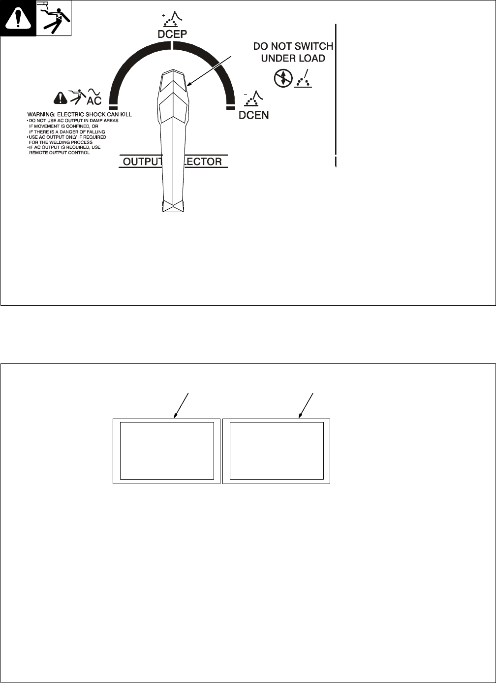
4-2. Output Selector Switch
Ref. ST-181 675-A
1 Output Selector Switch
YDo not use AC output in
damp areas, if movement is
confined, or if there is dan-
ger of falling. Use AC output
ONLY if required for the
welding process, and then
use a remote control.
YDo not change position of
switch while welding or
while under load.
Use switch to select (DCEN) Direct
Current Electrode Negative, AC, or
(DCEP) Direct Current Electrode
Positive output without changing
weld output cable connections.
1
4-3. Meters
1 Voltmeter
Voltmeter displays voltage at the
weld output terminals, but not nec-
essarily the welding arc due to
cable resistance, poor connec-
tions, etc.
2 Ammeter
Ammeter displays weld amperage
output of unit.
1 2
TM-353 Page 15Syncrowave 250
4-4. Crater Time Controls
1 Crater Time Control
Use control to reduce current over a
set period of time (0–15 seconds) at
the end of the weld cycle when NOT
using a remote current control.
2 Crater Time Switch
ON – provides crater time.
OFF – provides no crater time.
Place switch in the OFF position for
Shielded Metal Arc Welding
(SMAW).
Application:
Crater Time should be used while
GTAW welding materials that are
crack sensitive, and/or the operator
wants to eliminate the crater at the
end of the weld.
Note: This applies if the operator is
using an on/off only type control to
start and stop the welding process.
2
1
4-5. Spot Time Controls
1 Spot Time Switch
Place switch in the ON position to
turn on spot weld circuitry.
The (GTAW) TIG Spot process is
generally used with a direct current
electrode negative (DCEN) set-up.
Place switch in the OFF position to
turn off spot weld circuitry. Put
switch in the OFF position while do-
ing Shielded Metal Arc Welding
(SMAW).
2 Spot Time Control
Use control to set time (0–5.7 sec-
onds) for Gas Tungsten Arc
(GTAW) spot welds. Spot time be-
gins at arc initiation. If the arc is bro-
ken during the spot time cycle, the
timer stops but does not reset.
When the spot time has ended,
weld output stops. Postflow starts
when the remote contactor is
opened. The spot timer resets after
the contactor opens.
Application:
TIG spot welding is used for joining
thinner materials that are in close
contact, with the fusion method. A
good example would be joining coil
ends.
1
2
TM-353 Page 16 Syncrowave 250
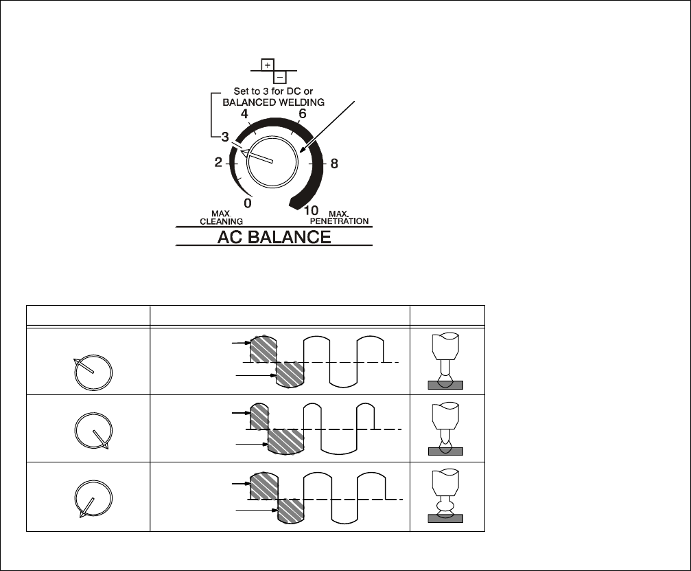
4-6. AC Balance Control
Ref. S-0795-A
1 AC Balance Control
Balance Control (AC GTAW):
Control changes the AC output
square wave. Rotating the control
towards 10 provides deeper pene-
tration. Rotating the control towards
0 provides more cleaning action of
the workpiece.
When the control is in the Balanced
position, the wave shape provides
equal penetration and cleaning
action.
Application:
When welding on oxide forming ma-
terials such as aluminum or magne-
sium, excess cleaning is not neces-
sary. To produce a good weld, only
a minimal amount, approximately a
0.10 in (2.5mm) of etched zone
along the weld toes is required.
Set control to 7 and adjust as nec-
essary. Joint configuration, set-up,
process variables, and oxide thick-
ness may affect setting.
Arc rectification can occur when
welding above 200 amps and/or
while welding with helium gas. If this
condition occurs, increasing the
Balance control towards maximum
penetration, may help to restabilize
the arc.
Balanced
3
10
0
More Penetration
More Cleaning
50% Electrode
Positive
50% Electrode
Negative
32% Electrode
Positive
68% Electrode
Negative
55% Electrode
Positive
45% Electrode
Negative
Output Waveforms ArcSetting
1
TM-353 Page 17Syncrowave 250
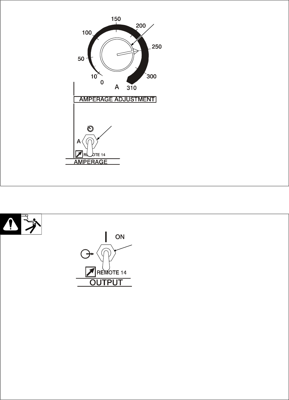
4-7. Amperage Adjustment Controls
1 Amperage Adjustment Control
Use control to adjust amperage,
and preset amperage on ammeter
(see Section 4-3). This control may
be adjusted while welding.
For remote amperage control,
front panel control setting is the
maximum amperage available. For
example: If front panel control is set
to 200 A, the range of the remote
amperage control is 5 to 200 A.
For spot welding, use Amperage
Adjust control to select from 5–310
amps of peak amperage (see Sec-
tion 4-5).
2 Amperage Control Switch
Use switch to select way of control-
ling amperage adjustment.
For front panel control, place switch
in the PANEL position.
For remote control, place switch in
REMOTE 14 position, and connect
remote control device (see Section
3-8).
1
2
4-8. Output (Contactor) Control Switch
YWeld output terminals are
energized when Output
(Contactor) switch is On and
Power is On.
1 Output/Contactor Switch
Use switch to select way of control-
ling unit output.
For front panel control, place switch
in ON position.
When On is selected, HF and gas
control are disabled.
For remote control, place switch in
REMOTE 14 position, and connect
remote control device (see Section
3-8).
1
TM-353 Page 18 Syncrowave 250
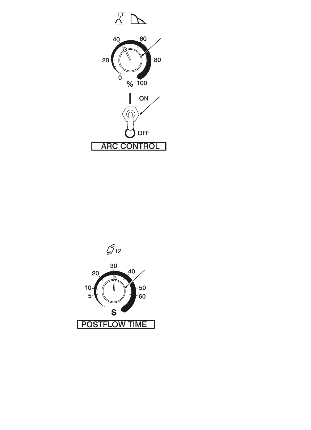
4-9. Arc Controls
1 Arc Control (Dig)
For AC And DC SMAW Welding
When set at 0, short-circuit amper-
age at low arc voltage is the same
as normal welding amperage.
When setting is increased, short-
circuit amperage at low arc voltage
increases.
Set at 0 for GTAW welding.
2 Arc Control Switch
Place switch in the ON position to
turn on arc control circuitry. When
switch is in the OFF position, no ad-
ditional amperage is available at
low arc voltages. Place switch in
the OFF position while performing
Gas Tungsten Arc Welding
(GTAW).
Application:
Control helps arc starting or making
vertical or overhead welds by in-
creasing amperage at low arc volt-
age, and reduces electrode sticking
while welding.
2
1
4-10. Postflow Time Control
1 Postflow Time Control
Use control to set length of time
(0–70 seconds) gas flows after
welding stops. It is important to set
enough time to allow gas to flow un-
til after the tungsten and weld
puddle has cooled down.
Application:
Postflow is required to cool tung-
sten and weld, and to prevent con-
tamination of tungsten and weld. In-
crease postflow time if tungsten or
weld are dark in appearance.
1
TM-353 Page 19Syncrowave 250
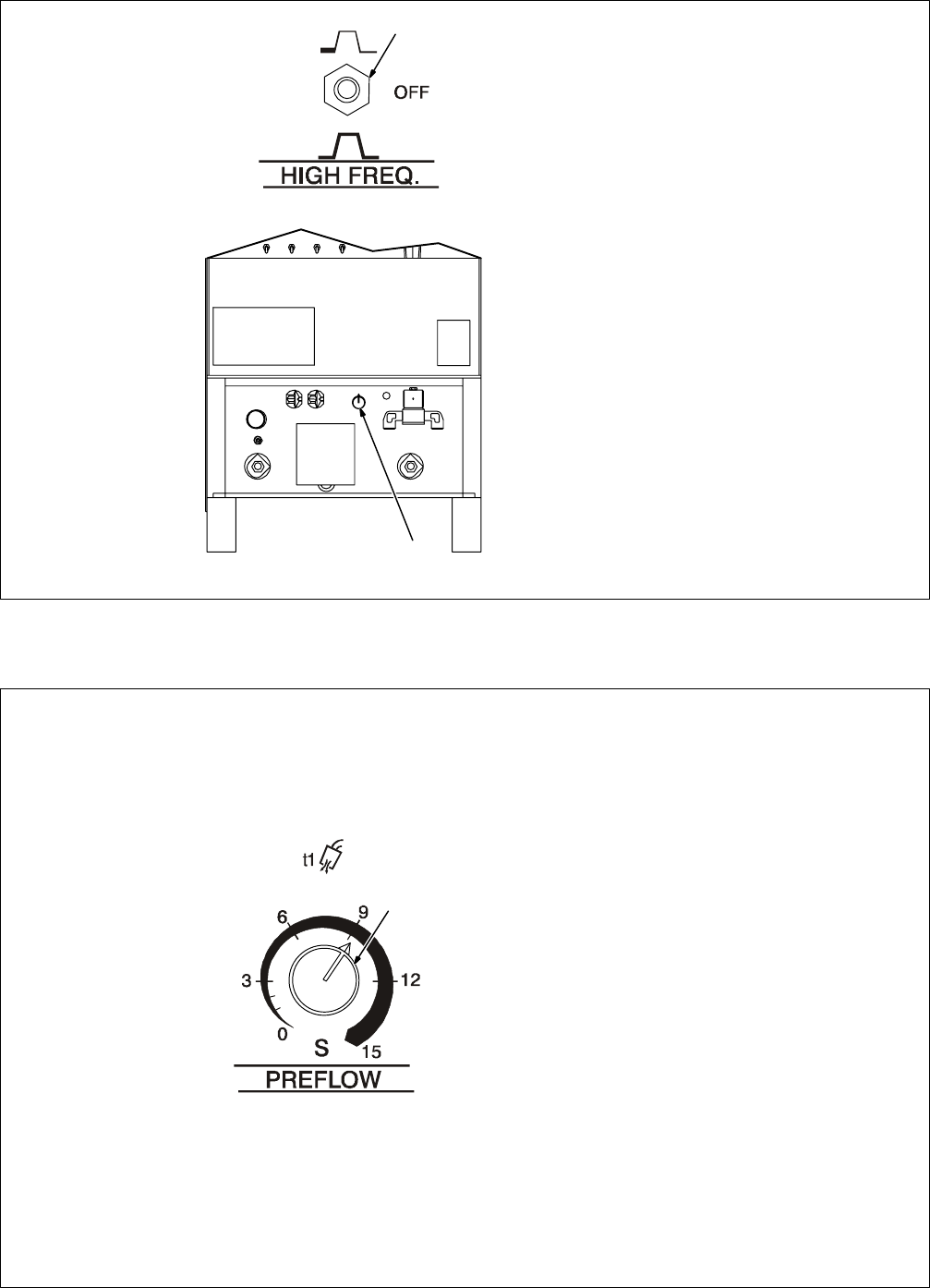
4-11. High Frequency Controls
YPlace High Frequency
switch in Off position before
using the shielded metal arc
welding (SMAW) process.
1 High Frequency Switch
START – (Up position) provides HF
for arc starting only. High frequency
turns on to help start arc when out-
put is enabled. High frequency
turns off when arc is started, and
turns on whenever arc is broken to
help restart arc.
Application:
HF Start is used when the DCEN
GTAW process is required.
OFF – provides no HF. Use OFF for
SMAW (stick electrode) welding.
CONTINUOUS – (Down position)
provides HF continuously through-
out the weld.
Application:
HF Continuous is used when the
AC GTAW process is required.
2 High Frequency Intensity
Control
Use control to change amount of
HF energy used to start and main-
tain the arc. Set as low as practical
to prevent interfering with electronic
equipment.
1
2
4-12. Preflow Time Control (Optional)
1 Preflow Time Control
Use control to set the length of time
(0–15 seconds) that gas flows be-
fore an arc is started.
Application:
Preflow is used to purge the imme-
diate weld area of atmosphere. Pre-
flow also aids in consistent arc
starting.
1
TM-353 Page 20 Syncrowave 250
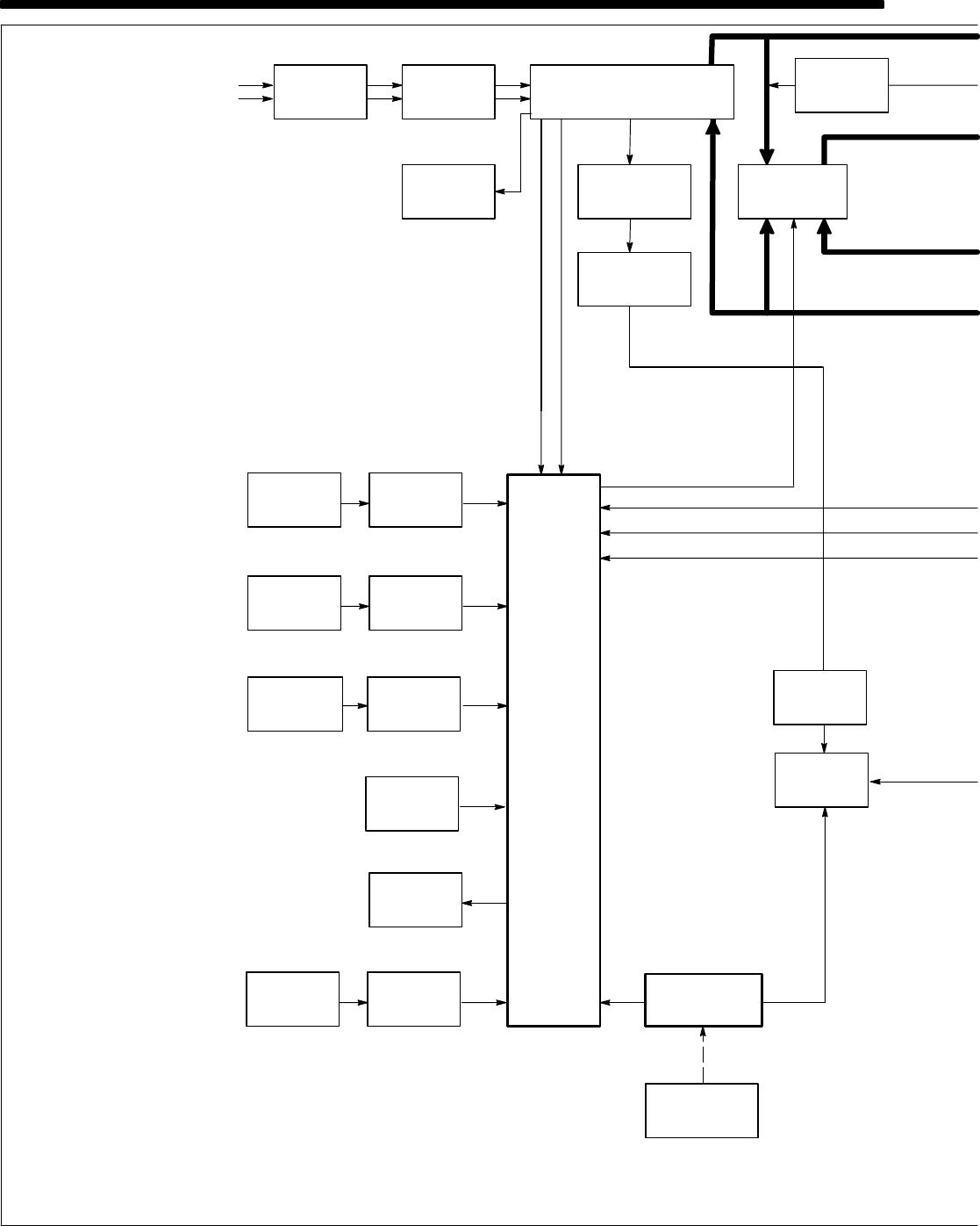
1 Input Terminal Board TE1
Provides means for operation on
different input voltages.
2 Power Switch S1
Provide on/off control of unit.
3 Fan Motor FM
Provides cooling of internal compo-
nents.
4 Main Transformer T1
Supplies power to weld output cir-
cuit, various control circuits, main
control board PC1, and fan motor
FM.
5 Control Board PC1
Controls weld output by changing
the SCR gate pulses (conduction
times) after comparing current
feedback to selected amperage
signal.
Also provides input connections for
switches S3, S5, S6, and S7.
6 Arc Control Switch S6 And
Control R2
R2 selects short-circuit amperage
when S6 is On, and High Frequen-
cy control R13 is Off.
7 Crater Time Switch S7 And
Control R11
R11 selects crater time when S7 is
on, and Amperage Control switch
S5 is in Panel position.
8 Thermostat TP1
If T1 overheats, TP1 opens stop-
ping all weld output.
9 Output (Contactor) Switch S3
Selects On or remote contactor
control.
10 AC Balance Control R3
Controls changes to ac output
square wave.
11 Ammeter A1 And Voltmeter
V1
Display weld amperage and volt-
age while welding.
12 Amperage Control Switch S5
And Adjustment Control R1
R1 selects weld output amperage
when S5 is in Panel.
13 Remote 14 Filter Board
PC2/Remote 14 Receptacle
RC1
PC2 protects unit from high fre-
quency, and RC1 connects remote
amperage and contactor controls to
power source.
14 Circuit Breaker CB1
Protects 115 volts ac duplex recep-
tacle RC2 from overload.
SECTION 5 – THEORY OF OPERATION
1-Phase
Input
Terminal
Board TE1
Power
Switch
S1
Main
Transformer
T1
Circuit
Breaker
CB1
115 VAC
115 VAC Duplex
Receptacle
RC2
Fan
Motor
FM
Control
Board
PC1
Arc Control
Output
Amperage
Crater Time
Switch
S6
Control
Switch S5
Switch
S7
AC
115 VAC
Thermostat
TP1
Line
Input
Power DC
Synchronization
Signal SCR
Gating
Signals
Main
Rectifier
SR1
1φ1φ
124
31423
15
6
9
12
7
5
8
Arc Control
R2
Amperage
Adjustment
Control R1
Crater Time
Control
R11
AC Balance
Control
R3
10
Ammeter
A1
11
Postflow
Timer
TD1
16
Gas
Valve
GS1
17
6
12
Remote
13
Remote 14
Filter Board
PC2
13
7
1φ, 10 VAC
(Contactor)
Switch S3
24
Background
Power
Source
Amperage
Control
♦
TM-353 Page 21Syncrowave 250
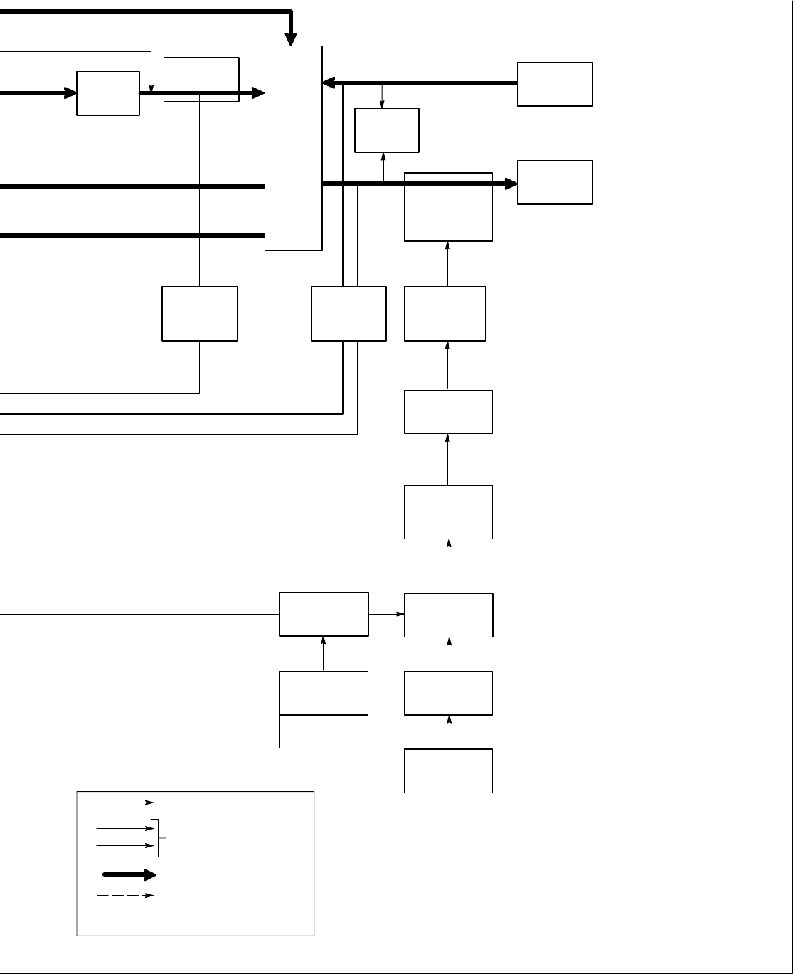
15 115 Volts AC Duplex Recep-
tacle RC2
Provides connection point for auxil-
iary equipment.
16 Postflow Timer TD1
Controls shielding gas and coolant
postflow time.
17 Gas Valve GS1
Provides shielding gas during the
weld cycle.
18 Preflow Timer TD3, Control
R12, And Switch S9
R12 selects time shielding gas
flows before arc starts. S9 is an in-
tegral part of R12 so that when R12
is turned past zero (0), TD3 is off.
19 Spot Timer TD2, Switch S8,
And Control R10
R10 selects time output is available
when spot welding. S8 selects Off
or spot welding with remote contac-
tor control.
20 High Frequency Transformer
T2
Steps up input voltage and charges
capacitor C4.
21 Spark Gaps G And High Fre-
quency Coupling Coil T3
G provides path for C4 to discharge
into T3. T3 supplies high-frequency
to welding circuit.
22 High Frequency Intensity
Control R13
Changes amount of HF energy
used to start and maintain the arc.
23 Main Rectifier SR1
Changes the ac output from T1 to
full-wave rectified dc.
24 Background Power Source
Provides reduced weld output rip-
ple at low weld output levels.
25 Stabilizer Z1
Smooths dc welding current.
26 Hall Device HD1
Provides current feedback signal to
PC1 through line filter FL1.
27 Line Filter FL1
Filters current feedback signal.
28 Output Selector Switch S4
Provides either AC or DC and out-
put polarity.
29 Integrated Rectifier SR2
Provides dc voltage feedback to
PC1.
30 Electrode And Work Weld
Output Terminals
Provide weld output.
Hall Device
HD1
Optional
AC Or DC Control
External Circuits
Weld Current Circuit
Stabilizer
Z1
Work Weld
Electrode
Output
Terminal
Weld Output
Terminal
High
Frequency
Coupling
Coil T3
Current Feedback
Voltage Feedback
High
Frequency
Intensity
Control R13
Spark Gaps G
High
Frequency
Transformer
T2
♦
1φ Power
25 26 28
30
21 30
22
21
20
Capacitor
C4
Integrated
Rectifier
SR2
29
Line
Filter
FL1
Preflow
Timer
TD3
Preflow Time
Control
R12
Switch
S9
♦
♦
Spot
Timer
TD2
Spot Time
Control
R10
♦
♦
Voltmeter
V1
18
18
19
19
11
27
115 VAC
Spot Time
19♦
Switch
S8
Output
Selector
Switch
S4
Voltage Feedback
♦

TM-353 Page 22 Syncrowave 250
SECTION 6 – TROUBLESHOOTING
6-1. Troubleshooting Table
.See Section 6-2 for test points and values and
Section 10 for parts location.
.Use MILLER Testing Booklet (Part No. 150 853)
when servicing this unit.
Trouble Remedy
Prior to Serial No. KG164875, no weld
output; unit completely inoperative –
Effective with Serial No. KG164875,
no weld output; unit completely inop-
erative; PL2 off.
Be sure line disconnect switch is in the On position.
Replace building line fuse(s) or reset circuit breaker(s) if open.
Check for proper electrical input connections (see Section 3-11).
Check for proper jumper link position (see Section 3-11).
Check Power switch S1 and replace if necessary.
Prior to Serial No. KG164875, no weld
output; fan runs – Effective with Serial
No. KG164875, no weld output; fan
runs; PL2 on.
If using remote control, place Output (Contactor) switch S3 in Remote 14 position, and connect re-
mote control to Remote 14 receptacle RC1 (see Sections 3-8 and Section 4-8). If remote is not being
used, place Output switch S3 in On position.
Check, repair or replace remote control device.
Allow a cooling period of approximately 15 minutes. If thermostats TP1 remain open, check continuity
and replace if necessary (see Section 3-3).
Check circuit breaker CB1, and reset if open (see Section 7-2).
Place Output Selector switch S4 in desired position (see Section 4-2).
Check optional preflow timer board TD3, and replace if necessary.
Check optional spot timer relay TD2 for proper connections and resistance. Replace TD2 if
necessary.
Check continuity of Spot Time switch S8. Check condition of contacts. Repair or replace S8 if neces-
sary.
Check SR1, and replace necessary components. If components are replaced, check capacitors C7
thru C10. Replace capacitor(s) if necessary.
Check control board PC1 and connections, and replace if necessary.
Effective with Serial No. KB110695, check resistance and connections of HD1; HD1 is 1600 ohms
±10% between pins 1 and 3 of plug PLG3. Check input and output voltages. Replace HD1 if
necessary.
Unit provides only minimum weld
output. Check position of Amperage Control switch S5 (see Section 4-7).
Increase Amperage Adjustment control R1 setting if a remote control is used (see Section 4-7).
Check, repair or replace remote control device.
Check resistance and connections of Amperage Adjustment control R1; R1 is 1000 ohms ±10%.
Replace R1 if necessary.
Check SCRs in main rectifier SR1, and replace if necessary. If any SCRs are replaced, Check capac-
itors C7 through C10 for a short or open, and check for proper connections. Replace C7 through C10
if necessary.
Check control board PC1 and connections, and replace if necessary.
Effective with Serial No. KB110695, check resistance and connections of HD1; HD1 is 1600 ohms
±10% between pins 1 and 3 of plug PLG3. Check input and output voltages. Replace HD1 if
necessary.
Unit provides only maximum weld
output. Check Amperage Adjustment control R1 for proper connections and resistance; R1 is 1000 ohms
±10%. Replace R1 if necessary.
Effective with Serial No. KB110695, check resistance and connections of HD1; HD1 is 1600 ohms
±10% between pins 1 and 3 of plug PLG3. Check input and output voltages. Replace HD1 if
necessary.
Check connections for continuity to shunt device on units with Serial No. prior to KB110695.
Check bypass capacitors C13, C14, C16, C17, C18, and C19 for broken leads, shorts, and leakage.
Replace if necessary.

TM-353 Page 23Syncrowave 250
Trouble Remedy
Check SCRs in main rectifier SR1, and replace if necessary. If any SCRs are replaced, Check capac-
itors C7 through C10 for a short or open, and check for proper connections. Replace C7 through C10
if necessary.
Check control board PC1 and connections, and replace if necessary.
Check connections to line filter FL1. Check input to PC1. Replace FL1 if necessary.
Erratic weld output. Check for poor or improper input or output connections. See Sections 3-11 and 3-8.
Replace electrode.
Check torch assembly, and replace if necessary.
Check fuse F2 in rectifier SR3 circuit, and replace if necessary.
If Amperage Control switch S5 is in the Remote position check, repair, or replace remote amperage
control device if necessary.
Check connections for continuity to shunt device on units with Serial No. prior to KB110695.
Check Amperage Adjustment control R1 for proper connections and resistance; R1 is 1000 ohms
±10%. Replace R1 if necessary.
Check bypass capacitors C13, C14, C16, C17, C18, and C19 for broken leads, shorts, and leakage.
Replace if necessary.
Check SCRs in main rectifier SR1, and replace if necessary. If any SCRs are replaced, Check capac-
itors C7 through C10 for a short or open, and check for proper connections. Replace C7 through C10
if necessary.
Check control board PC1 and connections, and replace if necessary.
No or limited ac balance control. Check AC Balance control R3 for proper connections and resistance; R3 is 5000 ohms ±10%.
Replace R3 if necessary.
Check control board PC1 and connections, and replace if necessary.
Check SCRs in main rectifier SR1, and replace if necessary. If any SCRs are replaced, Check capac-
itors C7 through C10 for a short or open, and check for proper connections. Replace C7 through C10
if necessary.
No crater fill time. Check position of Crater switch S7 (see Section 4-4).
Check position of Crater control R11 (see Section 4-4).
Be sure arc voltage is below 24 volts (see Section 3-2. Volt-Ampere Curves).
Check position of Amperage Control switch S5, S5 must be in Panel position (see Section 4-7).
Check control board PC1 and connections, and replace if necessary.
Crater fill time too long or does not
time out. Check position of Crater control R11 (see Section 4-4).
Check resistance and connections of Crater control R11; R11 is 5 meg ohms ±10%. Replace R11 if
necessary.
Check control board PC1 and connections, and replace if necessary.
No arc control. Place Arc Control switch S6 in the On position.
Place High Frequency switch S2 in the Off position.
Be sure arc voltage is below 24 volts (see Section 3-2. Volt-Ampere Curves).
Check position of Arc Control R2 (see Section 4-9).
Check fuse F1 in rectifier SR3 circuit, and replace if necessary.
Check resistance and connections of Arc control R2; R2 is 1000 ohms ±10%. Replace R1 if
necessary.
Check control board PC1 and connections, and replace if necessary.
Lack of high frequency at tungsten
electrode; difficulty in starting an arc. Use proper size tungsten for welding application.
Use shortest possible cables (see Section 3-7).
Check cables and torch for cracked or deteriorated insulation or bad connections. Repair or replace
necessary parts.
Be sure to disconnect SMAW electrode cable from weld output terminal when GTAW welding.
Decrease gas flow setting.
Use properly prepared tungsten.
Increase setting of High Frequency Intensity control R13 (see Section 4-11).
Check spark gaps G, and readjust if necessary (see 7-4).

TM-353 Page 24 Syncrowave 250
Trouble Remedy
No high frequency at spark gaps G. Check position of High Frequency switch S2 (see Section 4-11).
Place Output (Contactor) switch S3 in Remote position and be sure remote control is connected to
Remote receptacle RC1 (see Section 3-8).
Check circuit breaker CB1, and reset if open (see Section 7-2).
Check fuse F1 in rectifier SR2 circuit, and replace if necessary.
Check coil voltage and connections of contactor control relay CR1. Check continuity of coil and con-
dition of contacts. Replace CR1 if necessary.
Check coil voltage and connections of contactor control relay CR5. Check continuity of coil and con-
dition of contacts. Replace CR5 if necessary.
Check spark gaps G, and readjust if necessary (see Section 7-4).
Check resistance and connections of High Frequency Intensity control R13; R13 is 1.5 ohms ±10%.
Replace R1 if necessary.
Check capacitor C4 for a short or open, and check for proper connections. Replace C4 if necessary.
Check transformer T2 for signs of winding failure. Check continuity across windings, and check for
proper connections. Check secondary voltages. Replace T2 if necessary.
Check coupling coil T3 for signs of winding failure. Check continuity across windings, and check for
proper connections. Replace T3 if necessary.
Check control board PC1 and connections, and replace if necessary.
No preflow time (optional). Place Output (Contactor) switch S3 in Remote position and be sure remote control is connected to
Remote receptacle RC1 (see Section 3-8).
Check position of Preflow Time control R12.
Check continuity of Preflow Time switch S9. Check condition of contacts. Repair or replace S9 if nec-
essary.
Remove jumper link 1 on terminal strip 1T.
Check optional preflow timer board TD3, and replace if necessary.
Optional spot timer relay TD2 does not
time out. Place Spot Time switch S8 in the On position.
Remove jumper link 2 from terminal strip 1T.
Place Spot Time control R10 in desired position.
Check coil voltage and connections of spot timer relay TD2. Check continuity of coil and condition of
contacts. Replace TD2 if necessary.
Check coil voltage and connections of control relay CR3. Check continuity of coil and condition of
contacts. Replace CR3 if necessary.
Check coil voltage and connections of control relay CR1. Check continuity of coil and condition of
contacts. Replace CR1 if necessary.
Postflow timer does not time out. Check position of Postflow Time control setting (see Section 4-10).
Check Control relay CR5 contacts 2 and 5 for proper operation. Replace CR5 if necessary.
Check coil voltage and connections of gas valve GS1. Check continuity of coils. Replace GS1 if nec-
essary.
Check input voltage and connections to Postflow timer board TD1. Check continuity of contacts. Re-
place TD1 if necessary.
Check control board PC1 and connections, and replace if necessary.
No postflow time. Check position of Postflow Time control setting (see Section 4-10).
Place Output(Contactor) switch S3 in the Remote position, and connect a remote control to recep-
tacle RC1 according to Section 3-8.
Check coil voltage and connections of control relay CR5. Check continuity of coil and condition of
contacts. Replace CR5 if necessary.
Check coil voltage and connections of gas valve GS1. Check continuity of coils. Replace GS1 if nec-
essary.
Check input voltage and connections to Postflow timer board TD1. Check continuity of contacts. Re-
place TD1 if necessary.
Check control board PC1 and connections, and replace if necessary.
No gas flow. Place Output(Contactor) switch S3 in the Remote position, and connect a remote control to recep-
tacle RC1 according to Section 3-8.
Check circuit breaker CB1, and reset if open (see Section 7-2).

TM-353 Page 25Syncrowave 250
Trouble Remedy
Check Control relay CR2 contacts 4 and 7 for proper operation. Replace CR2 if necessary.
Check coil voltage and connections of gas valve GS1. Check continuity of coils. Replace GS1 if nec-
essary.
No power output at 115 volts ac recep-
tacle RC1; weld output available. Check circuit breaker CB1, and reset if open (see Section 7-2).
Fan motor FM does not run; weld out-
put available. Effective with Serial No.
KG164875, unit is equipped with Fan-
On-Demand, which only runs when
cooling is required.
Check and clear fan blade obstruction.
Check coil voltage and connections of fan motor FM, and replace if necessary.
Line fuse opens immediately when
solid-state contactor SR1 turns on in
DC mode only.
Check diode D1, and replace if necessary.
Check SCRs in main rectifier SR1, and replace if necessary. If any SCRs are replaced, Check capac-
itors C7 through C10 for a short or open, and check for proper connections. Replace C7 through C10
if necessary.
No control of weld output. Check position of Amperage Control switch S5 (see Section 4-7).
Check resistance and connections of Amperage Adjustment control R1; R1 is 1000 ohms ±10%.
Replace R1 if necessary.
Check, repair or replace remote control device.
Effective with Serial No. KB110695, check resistance and connections of HD1; HD1 is 1600 ohms
±10% between pins 1 and 3 of plug PLG3. Check input and output voltages. Replace HD1 if
necessary.
Check control board PC1 and connections, and replace if necessary.
Tungsten electrode oxidizing and not
remaining bright after conclusion of
weld.
Check position of Postflow Time control R12 (see Section 4-10).
Check and tighten all gas fittings if necessary.
Increase gas flow setting.
Shield weld zone from drafts.
Properly prepare tungsten.
Place High Frequency switch S2 in Start or Continuous position.
Wandering arc - poor control of direc-
tion of arc. Use proper size tungsten for welding application.
Properly prepare tungsten.
Controls connected to Remote 14
receptacle RC1 do not work properly. Check, repair or replace remote control device.
Check Amperage Control switch S5 position (see Section 4-7). Check and replace S5 if necessary.
Check Output (Contactor) switch S3 position (see Section 4-8). Check and replace S3 if necessary.
Check position of jumper links 1 and 2 on terminal strip 1T according to Section 6-2.
Check coil voltage and connections of control relay CR2. Check continuity of coil and condition of
contacts. Replace CR2 if necessary.
Prior to Serial No. KF959379, check choke RFC1 connections. Check continuity of RFC1. Replace if
necessary. Effective with Serial No. KF959379 check remote 14 filter board PC2 (see Section 6-6).
Replace PC2 if necessary.
Check control board PC1 and connections, and replace if necessary.
Ammeter A1 not displaying correct
weld output amperage. Calibrate ammeter as instructed in Section 6-8.
Check ammeter A1 voltage; +1 millivolts dc per 3 ampere of weld output. Replace A1 if necessary.
Check control board PC1 and connections, and replace if necessary.
Effective with Serial No. KB110695, check resistance and connections of hall device HD1; HD1 is
1600 ohms ±10% between pins 1 and 3 of plug PLG3. Check input and output voltages. Replace HD1
if necessary.
Voltmeter V1 not displaying correct arc
voltage. Check connections for continuity to voltmeter V1. Replace V1 if necessary.
Electronic equipment in welding area
not working properly. HF interference problem. Check for proper installation, and correct problem (see Section 8).
TM-353 Page 26 Syncrowave 250
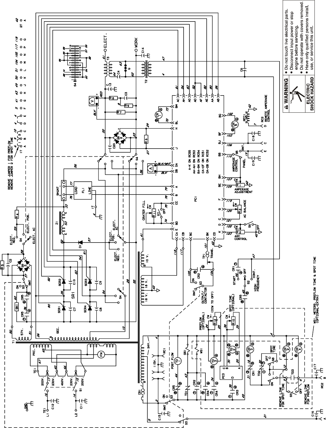
6-2. Troubleshooting Circuit Diagram For Welding Power Source
YDisable high frequency by placing High Frequency
switch S2 in Off position before testing unit.
R1
V2
V3
V1
V4
V5
V6
V13
V14
V15 V16
Link 1 Link 2
V7
V8
V9
V10
V11
V17
V12
R1
R1
See Section 3-8
for RC1
information
TD1 begins to time out
when CR5 deenergizes
TD3 begins to time out
when CR4 energizes
See Figure 9-19
for PC3 circuit
CR3 energizes during spot time
when an arc is detected CR4 energizes when remote contactor
switch closes
CR2 energizes when
remote contactor
switch closes
See Section 6-6
for PC2 data
R1
V25
TM-353 Page 27Syncrowave 250
SC-188 161
Test Equipment Needed:
V24
V22
V21
R3
R2
V20
AA
A
A
R1
V25
Resistance Values
a) Tolerance – ±10% unless specified
b) Turn Off unit and disconnect input
power before checking resistance
R1 All values for T1, Z1, and T3 are less
than 1 ohm
R2 5.3 ohms
R3 6.1 K ohms
Voltage Readings
a) Tolerance – ±10% unless
specified
b) Reference – to circuit
common (lead 42) unless
noted
c) Wiring Diagram – see
Section 10
V1 230 volts ac
V2 77 volts ac
V3 82.5 volts ac
V4 57 volts ac
V5, V6 115 volts ac
V7 24 volts ac
V8, V9 18 volts ac
V10 10 volts ac
V11 80 volts dc
V12. V13, V14 115 volts ac
V15, V16, V17 24 volts ac
V18 115 volts ac with S2
in Start or Con-
tinuous
V19 0 to +10 volts dc
with contactor on
V20, V21 24 volts dc
V22 0-80 volts dc (rec-
tified arc voltage)
V23 maximum 80 volts
ac/dc
V24 24 volts dc
V25 16.5 millivolts dc
per 1 ampere of
weld output
CR1 energizes
when open-circuit voltage
is present; denergizes
when an
arc is struck
See Figure 10-1 for
HD1 location No calibration available
for voltmeter V1
R1
V23, B,
C, D, E
See Section 6-3
for waveforms
B, C, D, E
See also
Sections 6-4 and 6-5
for PC1 data
CR5 energizes when
contactor is on
See Section 6-8
for ammeter A1
calibration
V19
V18
See Section 6-3
for waveform A
TM-353 Page 28 Syncrowave 250
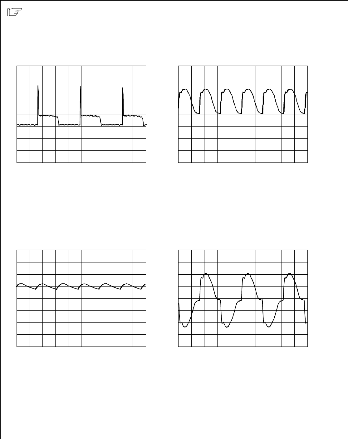
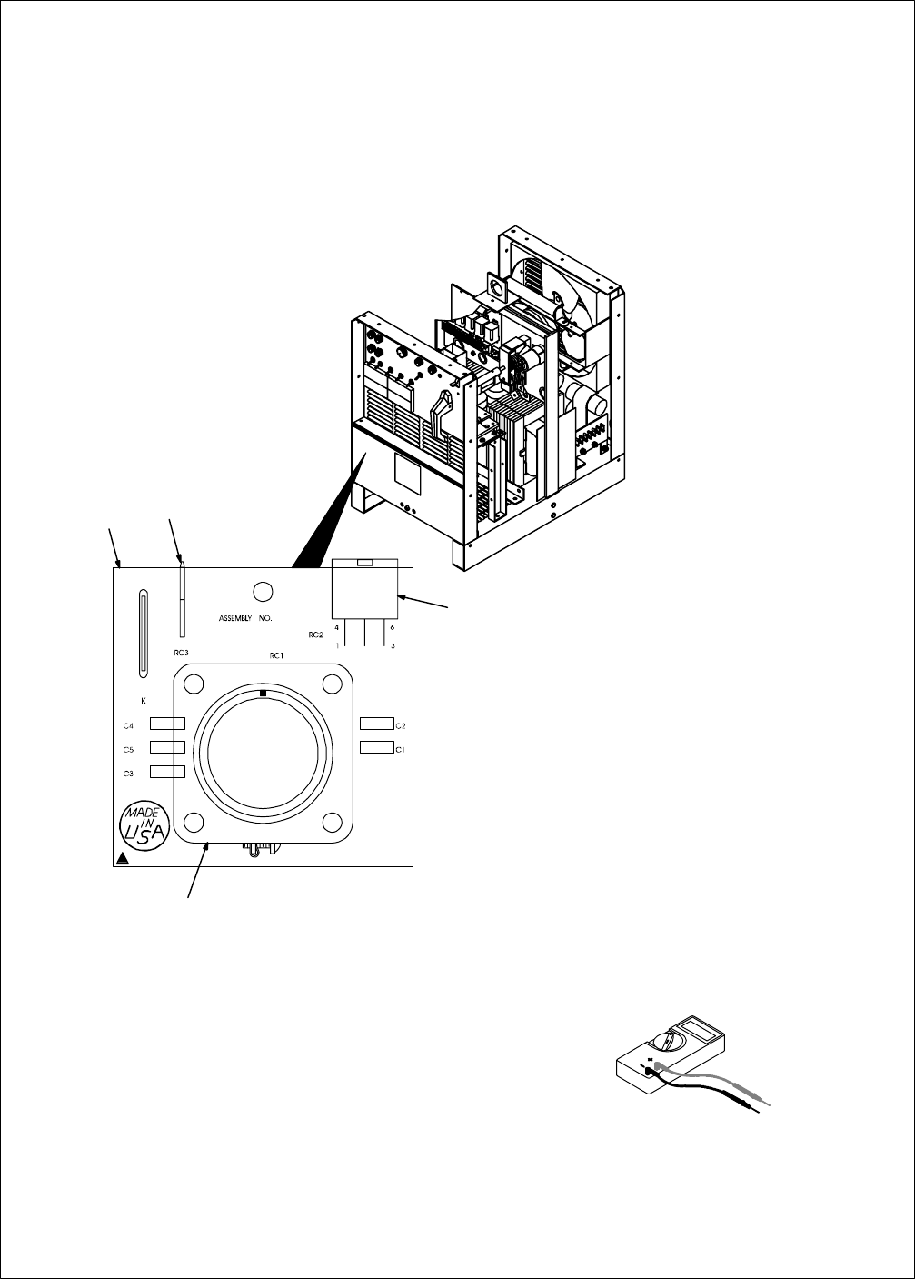
6-3. Waveforms For Section 6-2
Waveforms shown are for 60 Hertz models;
waveforms for 50 Hertz models are similar.
5 ms 1 V
A. SR1 Gate Pulse With Respect To Cathode
At No Load
5 ms 50 V
B. DC Open-Circuit Voltage With Amperage
Adjustment Control At Maximum
5 ms 20 V
C. DC Output, 100 Amperes, 24 Volts DC
(Resistive Load)
5 ms 50 V
D. AC Open-Circuit Voltage With Amperage
Adjustment Control At Maximum
gnd
gnd
gnd gnd
TM-353 Page 29Syncrowave 250
Test Equipment Needed:
5 ms 50 V
E. AC Output, 100 Amperes, 24 Volts AC (Re-
sistive Load)
gnd
TM-353 Page 30 Syncrowave 250
6-4. Control Board PC1 Testing Information (Use With Section 6-5)
SB-178 976-A / ST-800 344-A
YDisable high frequency by
placing High Frequency
switch S2 in Off position
before testing unit.
Be sure plugs are secure before
testing. See Section 6-5 for specific
values during testing.
1 Control Board PC1
2 Receptacle RC51
3 Receptacle RC52
4 Receptacle RC53
5 Receptacle RC54
6 Receptacle RC55
Test Equipment Needed:
123
4
5
6

TM-353 Page 31Syncrowave 250
6-5. Control Board PC1 Test Point Values
PC1 Voltage Readings
a) Tolerance – ±10% unless
specified
b) Reference – to circuit common
(lead 42) unless noted
Receptacle Pin Value
RC51 1 18 volts ac input
218 volts ac input
3+10 volts dc output
4Circuit common
5Not used
6Not used
RC52 1 Circuit common
2+1 millivolt dc per 3 ampere of weld output
RC53 1 Gate pulse for SCR1 with respect to pin 2 (see Section 6-3)
2Reference for gate pulse to SCR1
3Gate pulse for SCR3 with respect to pin 4 (see Section 6-3)
4Reference for gate pulse to SCR3
5Gate pulse for SCR2 with respect to pin 6 (see Section 6-3)
6Reference for gate pulse to SCR2
7Gate pulse for SCR4 with respect to pin 8 (see Section 6-3)
8Reference for gate pulse to SCR4
RC54 1 Not used
20 to +10 volts dc input from min. to max. of Amperage Adjustment control R1 with Amperage Control
switch S5 in Panel position, and contactor on
30 volts with Output (Contactor) switch S3 in On position or +7.8 volts dc with S3 in Remote position
40 to +10 volts dc input from min. to max. of Crater Control R11 with Crater Fill switch S7 in On posi-
tion, or +10 volts dc with S7 in Off position
5+10 volts dc output with Output (Contactor) switch S3 in On position
6–24 volts dc
7–24 volts dc with contactor on or off
80 to +10 volts dc input from min. to max. of Amperage Adjustment control R1 with contactor on
90 to +10 volts dc input from min. to max. of Amperage Adjustment control R1 with contactor on
10 Circuit common
11 +24 volts dc
12 0 volts during open-circuit voltage condition; +24 volts with arc on or contactor off

TM-353 Page 32 Syncrowave 250
Receptacle ValuePin
RC55 1 Circuit common
2+1.65 volts dc per 100 amperes of weld output with respect to pin 1
3–15 volts dc output
40 to +4 volts dc input from min. to max. of Arc Control R2 with Arc Control switch S6 On
510 volts ac input for synchronization
6+5.8 volts dc output
7–15 volts dc input from Max. Penetration setting of AC Balance control R3 to +5.8 volts dc input at
Max. Cleaning setting of R3
80 to 80 volts dc voltage feedback signal (rectified arc voltage) with respect to pin 9
90 to 80 volts dc voltage feedback signal (rectified arc voltage) with respect to pin 8
10 0 to +4 volts dc input from min. to max. of Arc Control R2 with Arc Control switch S6 Off
TM-353 Page 33Syncrowave 250
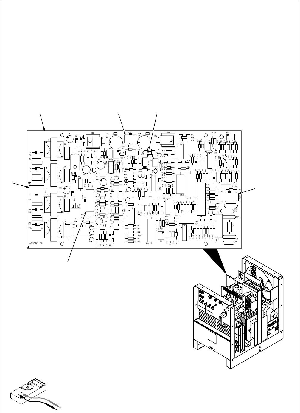
6-6. Remote Board PC2 Testing Information (Use With Section 6-7)
ST-157 960-B / ST-800 344-A
YDisable high frequency by
placing High Frequency
switch S2 in Off position
before testing unit.
Be sure plugs are secure before
testing. See Section 6-7 for specific
values during testing.
1 Remote 14 Filter Board PC2
2 Remote 14 receptacle RC1
See Section 3-8 for information.
3 Receptacle RC2
4 Receptacle RC3
Test Equipment Needed:
2
3
14

TM-353 Page 34 Syncrowave 250
6-7. Remote 14 Filter Board PC2 Test Point Values (Use With Section 6-2 And Section 6-6)
PC2 Voltage Readings
a) Tolerance – ±10% unless
specified
b) Reference – to circuit common
(lead 42) unless noted
Receptacle Pin Value
RC1 A 24 volts ac
BContact closure to A completes 24 volts ac contactor control circuit
CCommand reference; 0 to +10 volts dc output to remote control
DRemote control circuit common
E0 to +10 volts dc input command signal from remote control
KChassis common
RC2 1 Command reference; 0 to +10 volts dc output to remote control
3Contact closure to A completes 24 volts ac contactor control circuit
4Remote control circuit common
50 to +10 volts dc input command signal from remote control
624 volts ac
RC3 1 Chassis common
TM-353 Page 35Syncrowave 250
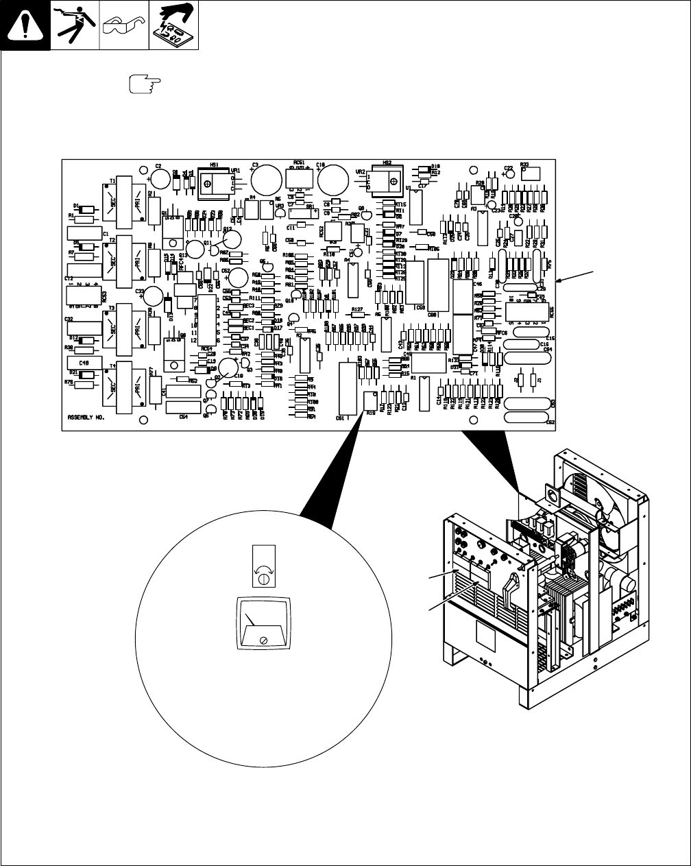
6-8. Meter Calibration
SB-130 690-D / ST-800 344-A
Be sure plugs are secure before
calibrating meter.
1 Control Board PC1
2 Voltmeter V1
3 Ammeter A1
Top View
R19
Amperes
No calibration available for ammeter
offset, or for voltmeter V1.
1
2
3
Adjust R19 for amperage gain to
match external calibrated meter
using load bank set at desired
load.
TM-353 Page 36 Syncrowave 250
6-9. Input Voltage Labels And Connections
ST-154 793-A / ST-114 947-A / ST-121 000-A / ST-131 735
1 Input Voltage Label And Con-
nection Diagram – Only One
Label Is On Unit
2 Terminal Strip TE1
Test Equipment Needed:
1
2
TM-353 Page 37Syncrowave 250
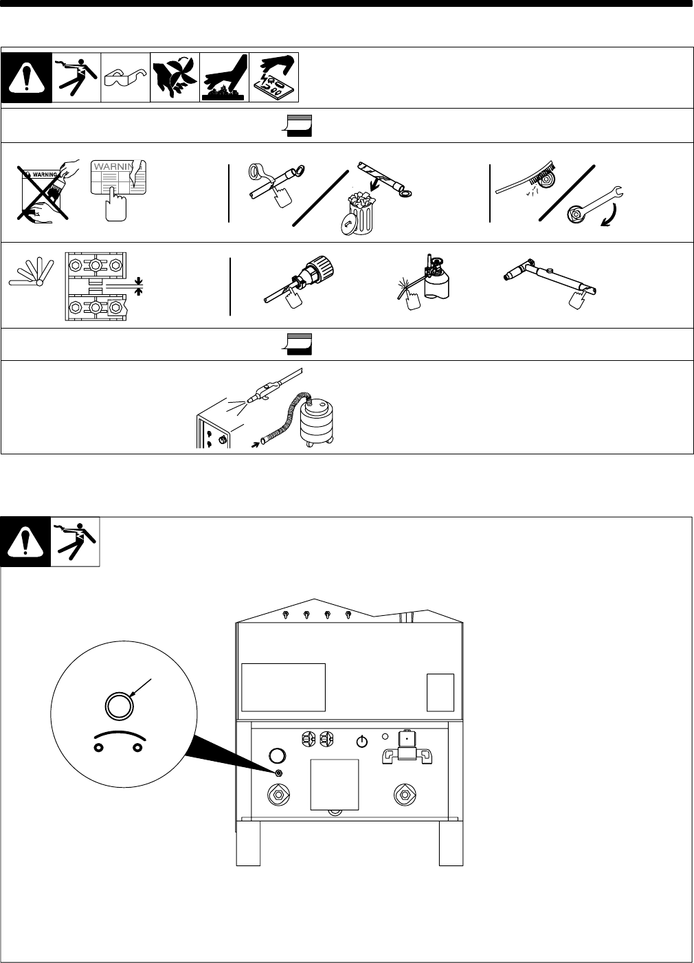
SECTION 7 – MAINTENANCE
7-1. Routine Maintenance
YDisconnect power before maintaining.
3 Months
Replace
Unreadable
Labels
Clean And
Tighten
Weld
Terminals
Repair Or
Replace
Cracked
Weld
Cables
Adjust Spark
Gaps Replace
Cracked
Parts
14-Pin Cord Gas Hose Torch Cable
6 Months
OR
Blow Out Or Vacuum
Inside,
During Heavy Service,
Clean Monthly
7-2. Circuit Breaker CB1
Ref. ST-154 795-C
1 Circuit Breaker CB1
If CB1 opens, output to the 115 volts
ac duplex receptacle, high frequen-
cy, and gas flow stop. Press button
to reset breaker.
1
CB1
TM-353 Page 38 Syncrowave 250
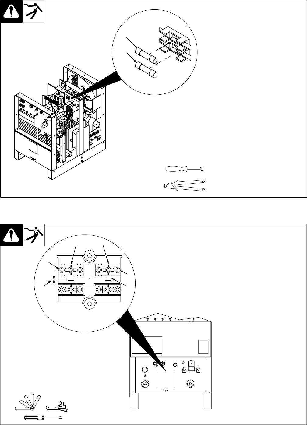
7-3. Fuses F1 And F2
1 Fuse F1 (See Parts List For
Rating)
Fuse F1 (between leads 50 and
150) protects wiring harness from
shorted SR2. If F1 opens, you may
experience problems with arc start-
ing and arc performance in the DC
TIG mode.
2 Fuse F2 (See Parts List For
Rating)
Fuse F2 (between leads 22 and
149) protects wiring harness from
shorted SR3. If F2 opens, you may
experience problems with arc con-
trol, and no high frequency in start
high frequency.
Tools Needed:
1
2
3/8 in
7-4. Adjusting Spark Gaps
Ref. ST-154 795-C / Ref. S-0043
Tools Needed:
1
4
3
4
3
2
YTurn Off power before
adjusting spark gaps.
Open access door.
1 Tungsten End Of Point
Replace point if tungsten end dis-
appears; do not clean or dress
tungsten.
2 Spark Gap
Normal spark gap is 0.008 in (0.203
mm).
If adjustment is needed, proceed as
follows:
3 Adjustment Screws
Loosen screws. Place gauge of
proper thickness in spark gap.
4 Pressure Point
Apply slight pressure at point until
gauge is held firmly in gap. Tighten
screws to 12 in/lbs torque (overtigh-
tening will deform plastic base). Ad-
just other gap.
Close access door.
TM-353 Page 39Syncrowave 250
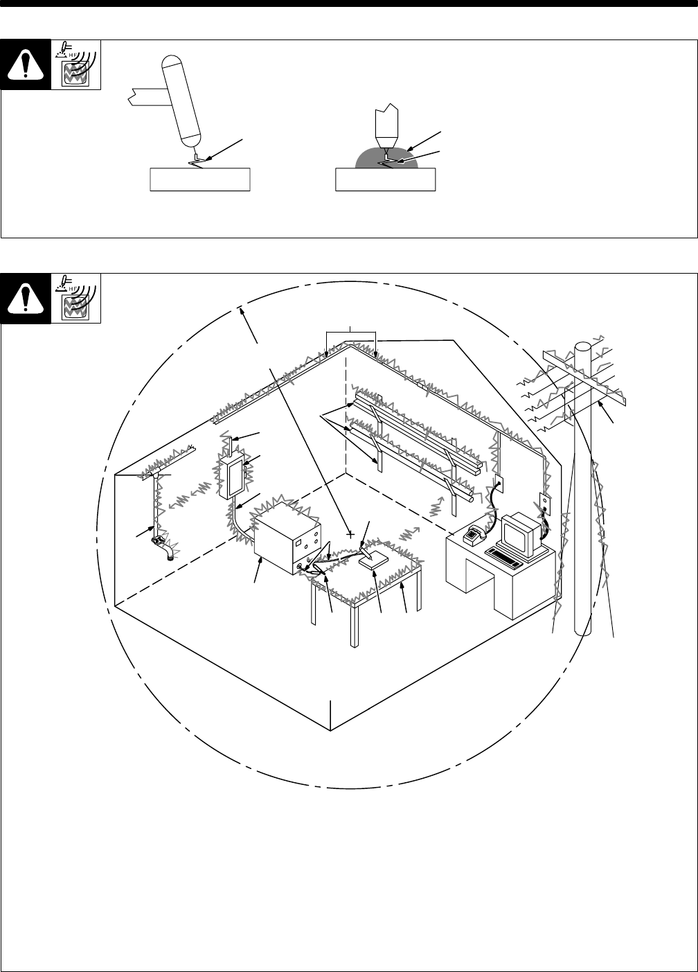
SECTION 8 – HIGH FREQUENCY (HF)
8-1. Welding Processes Using HF
high_freq1 7/95 – S-0693
1 HF Voltage
GTAW – helps arc jump air gap
between torch and workpiece and/
or stabilize the arc.
SAW – helps arc reach workpiece
through flux granules.
2 Flux
12
1
Gas Tungsten Arc
Welding (GTAW) Submerged Arc
Welding (SAW)
Work Work
50 ft
(15 m)
S-0694
Sources Of Direct HF Radiation
1 HF source (welding power source with
built-in HF or separate HF unit)
2 Weld Cables
3 Torch
4 Work Clamp
5 Workpiece
6 Work Table
Sources Of Conduction Of HF
7 Input Power Cable
8 Line Disconnect Device
9 Input Supply Wiring
Sources Of Reradiation Of HF
10 Ungrounded Metal Objects
11 Lighting
12 Wiring
13 Water Pipes And Fixtures
14 External Phone And Power Lines
8-2. Sources Of HF Radiation From Incorrect Installation
Weld Zone
13
9
8
7
1
2
4 5 6
3
10
11, 12
14
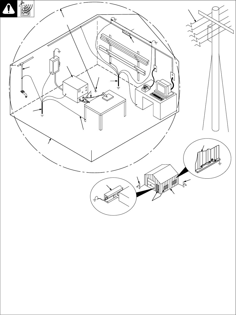
TM-353 Page 40 Syncrowave 250
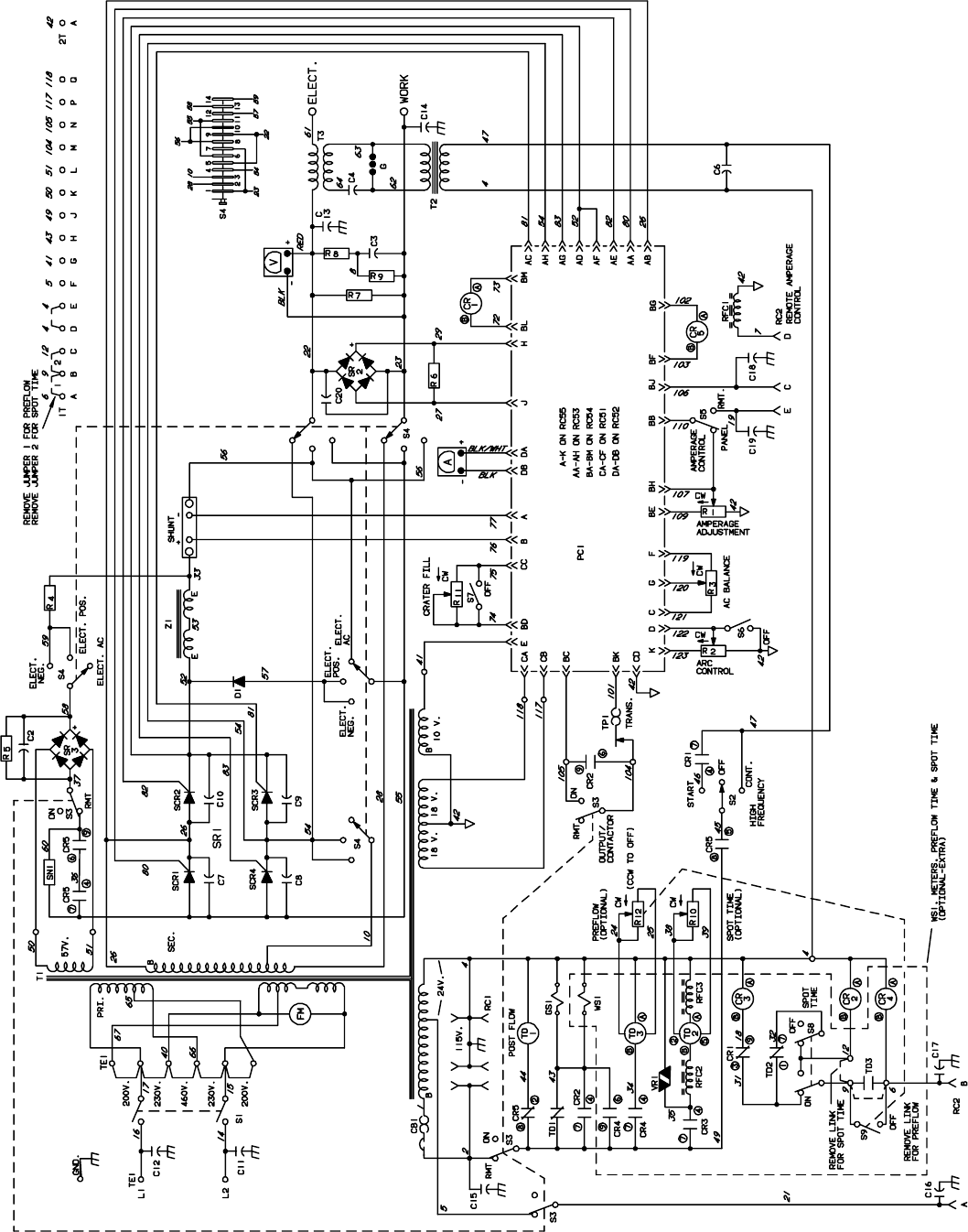
8-3. Correct Installation
1 HF Source (Welder With Built-In HF Or
Separate HF Unit)
Ground metal machine case, work output
terminal, line disconnect device, input
supply, and worktable.
2 Welding Zone And Centerpoint
A circle 50 ft (15 m) from centerpoint
between HF source and welding torch in all
directions.
3 Weld Output Cables
Keep cables short and close together.
4 Conduit Joint Bonding And Grounding
Electrically join (bond) all conduit sections
using copper straps or braided wire. Ground
conduit every 50 ft (15 m).
5 Water Pipes And Fixtures
Ground water pipes every 50 ft (15 m).
6 External Power Or Telephone Lines
Locate HF source at least 50 ft (15 m) away
from power and phone lines.
7 Grounding Rod
Consult the National Electrical Code for
specifications.
8 Metal Building Panel Bonding Methods
Bolt or weld building panels together, install
copper straps or braided wire across seams,
and ground frame.
9 Windows And Doorways
Cover all windows and doorways with
grounded copper screen of not more than
1/4 in (6.4 mm) mesh.
10 Overhead Door Track
Ground the track.
Ref. S-0695 / Ref. S-0695
1
2
50 ft
(15 m)
Weld Zone
3
6
50 ft
(15 m)
7
4
7
5
Ground
Workpiece
If Required
By Codes
Ground All
Metal Objects
And All Wiring
In Welding Zone
Using #12 AWG
Wire
Nonmetal
Building
8
10
9
Metal Building
77

TM-353 Page 41Syncrowave 250
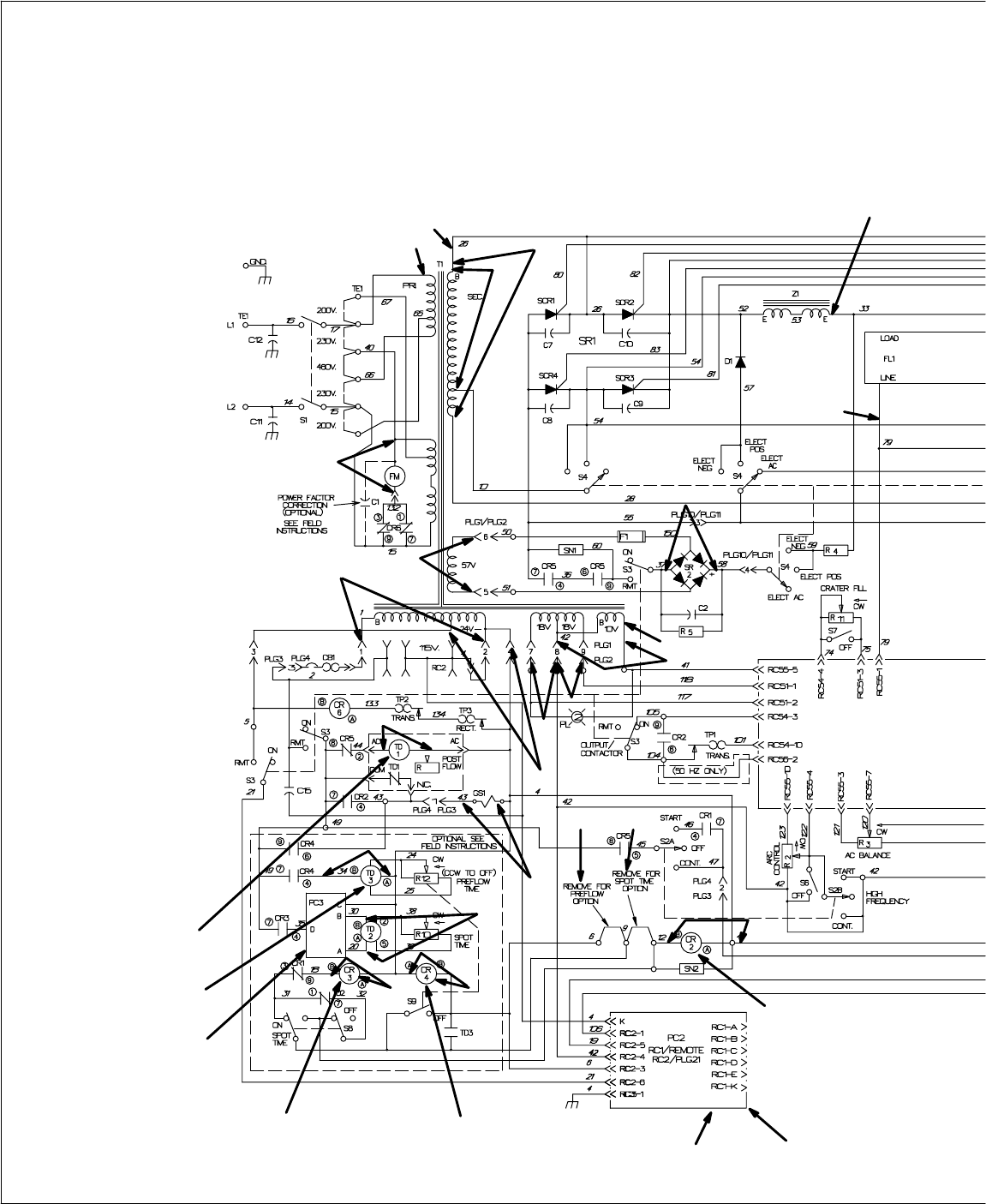
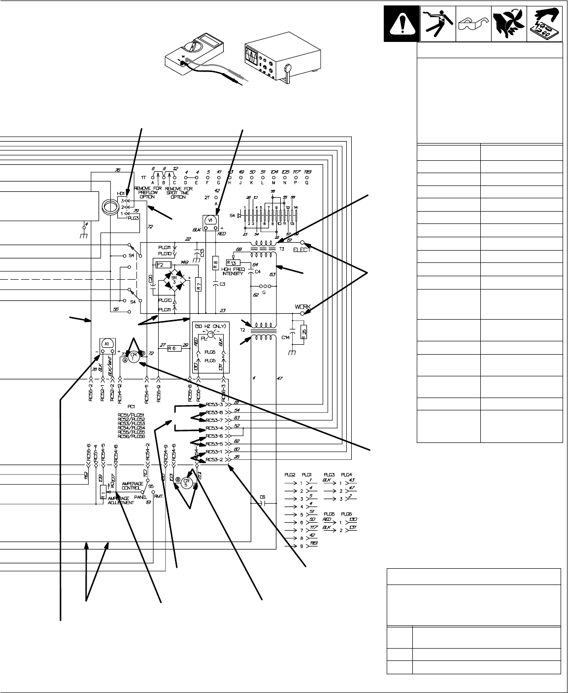
SECTION 9 – ELECTRICAL DIAGRAMS
.The circuits in this manual can be used for troubleshooting, but there might be minor circuit differences from your machine. Use circuit inside
machine case or contact distributor for more information.
The following is a list of all diagrams for models covered by this manual.
Model Serial Or Style Number Circuit Diagram Wiring Diagram
Syncrowave 250 JJ339876 thru JJ351864 SC-114 914 D-116 884-B♦♦
JJ351865 thru JJ365633 SC-120 877 D-120 878-B♦♦
JJ365634 thru JJ503983 SC-121 280 D-121 281-D♦♦
JJ503984 thru JK572897 SC-124 314 D-124 307-C♦♦
JK572898 thru JK617846 SC-124 785-B D-124 786-B♦♦
JK617847 thru JK682713 SC-124 785-B D-129 200-B♦♦
JK682714 thru JK690986 SC-124 785-B D-130 576-B♦♦
JK690987 thru KA806712 SC-132 697-A D-132 431-D♦♦
KA806713 thru KA877024 SC-137 431 D-137 430-A♦♦
KA877025 thru KB010829 SC-135 581 D-135 734-A♦♦
KB010830 thru KB110694 SC-142 524 D-142 525-A♦♦
KB110695 thru KC252675 SC-148 144 D-148 145-A♦♦
KC252676 thru KG029204 SC-154 649-C D-154 648-E♦♦
KG029205 thru KG062109 SC-178 835 D-174 039-A♦♦
KG062110 thru KG170300 SC-179 303-A D-179 305-A♦♦
KG170301 thru KH526230 SC-181 109-E SD-181 110-F♦♦
KH526231 and following SC-188 161-A SD-188162-A
Circuit Board PC1 JJ339876 thru JJ399987 D-118 765♦♦
JJ399988 thru JK682713 D-122 270♦♦
JK682714 thru KA797306 D-130 691-A♦♦
KA797307 thru KG062109 D-135 253♦♦
KG062110 thru KH508254 SD-178 975♦♦
KH508255 and following SD-187644
RFC Circuit Board PC2 JJ365634 thru KB010829 SA-121 282
Remote 14 Filter Board PC2 KF959379 and following SA-158 763
Circuit Board PC3♦JJ351865 and following SA-120 872
Timer TD1 JJ339876 and following SA-044 725-C
Timer TD3♦JJ339876 and following SA-045 288-D
♦Optional
♦♦ Not included in this manual
TM-353 Page 42 Syncrowave 250
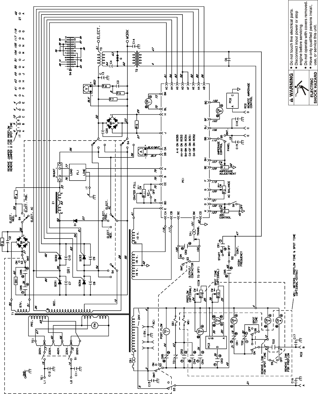
SC-114 914
Figure 9-1. Circuit Diagram For Syncrowave 250 Effective With Serial No. JJ339876 Thru JJ351864
TM-353 Page 43Syncrowave 250
Figure 9-2. Circuit Diagram For Syncrowave 250 Effective With Serial No. JJ351865 Thru JJ365633
SC-120 877
TM-353 Page 44 Syncrowave 250
SC-121 280
Figure 9-3. Circuit Diagram For Syncrowave 250 Effective With Serial No. JJ365634 Thru JJ503983
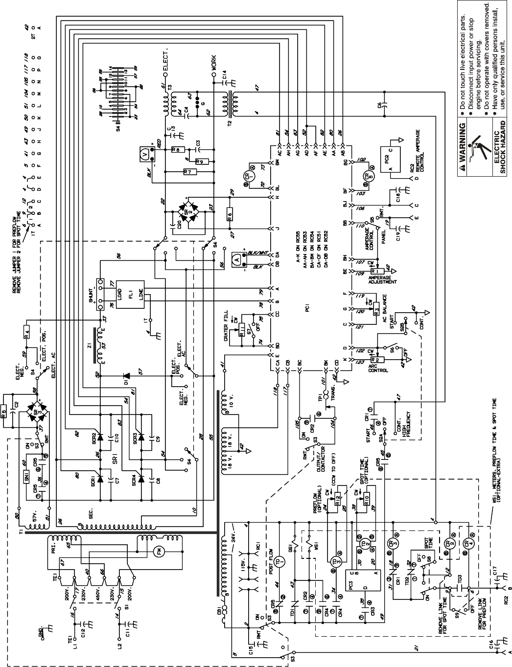
TM-353 Page 45Syncrowave 250
Figure 9-4. Circuit Diagram For Syncrowave 250 Effective With Serial No. JJ503984 Thru JK572897
SC-124 314
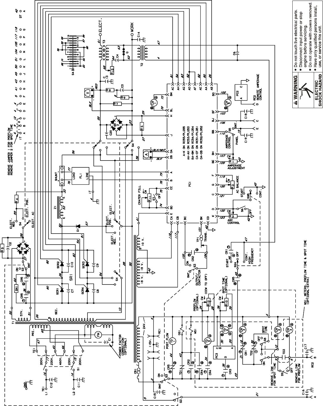
TM-353 Page 46 Syncrowave 250
SC-124 785-B
Figure 9-5. Circuit Diagram For Syncrowave 250 Effective With Serial No. JK572898 Thru JK690986
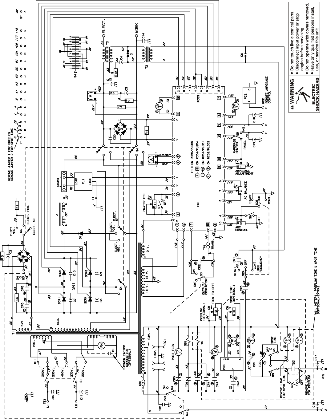
TM-353 Page 47Syncrowave 250
Figure 9-6. Circuit Diagram For Syncrowave 250 Effective With Serial No. JK690987 Thru KA806712
SC-132 697-A

TM-353 Page 48 Syncrowave 250
Figure 9-7. Circuit Diagram For Syncrowave 250 Effective With Serial No. KA806713 Thru KA877024
SC-137 431
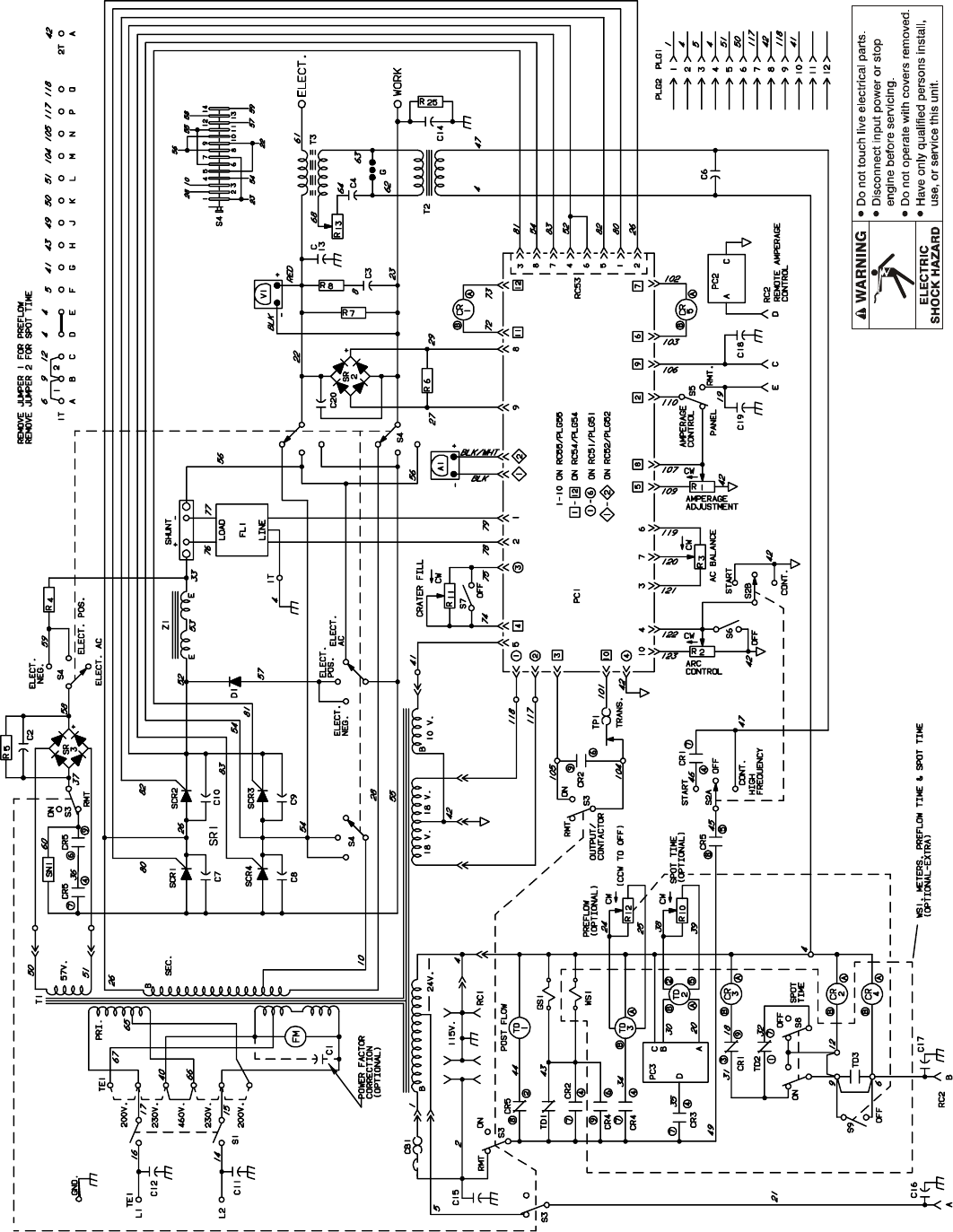
TM-353 Page 49Syncrowave 250
Figure 9-8. Circuit Diagram For Syncrowave 250 Effective With Serial No. KA877025 Thru KB010829
SC-135 581
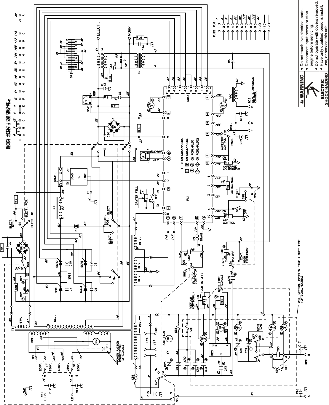
TM-353 Page 50 Syncrowave 250
Figure 9-9. Circuit Diagram For Syncrowave 250 Effective With Serial No. KB010830 Thru KB110694
SC-142 524
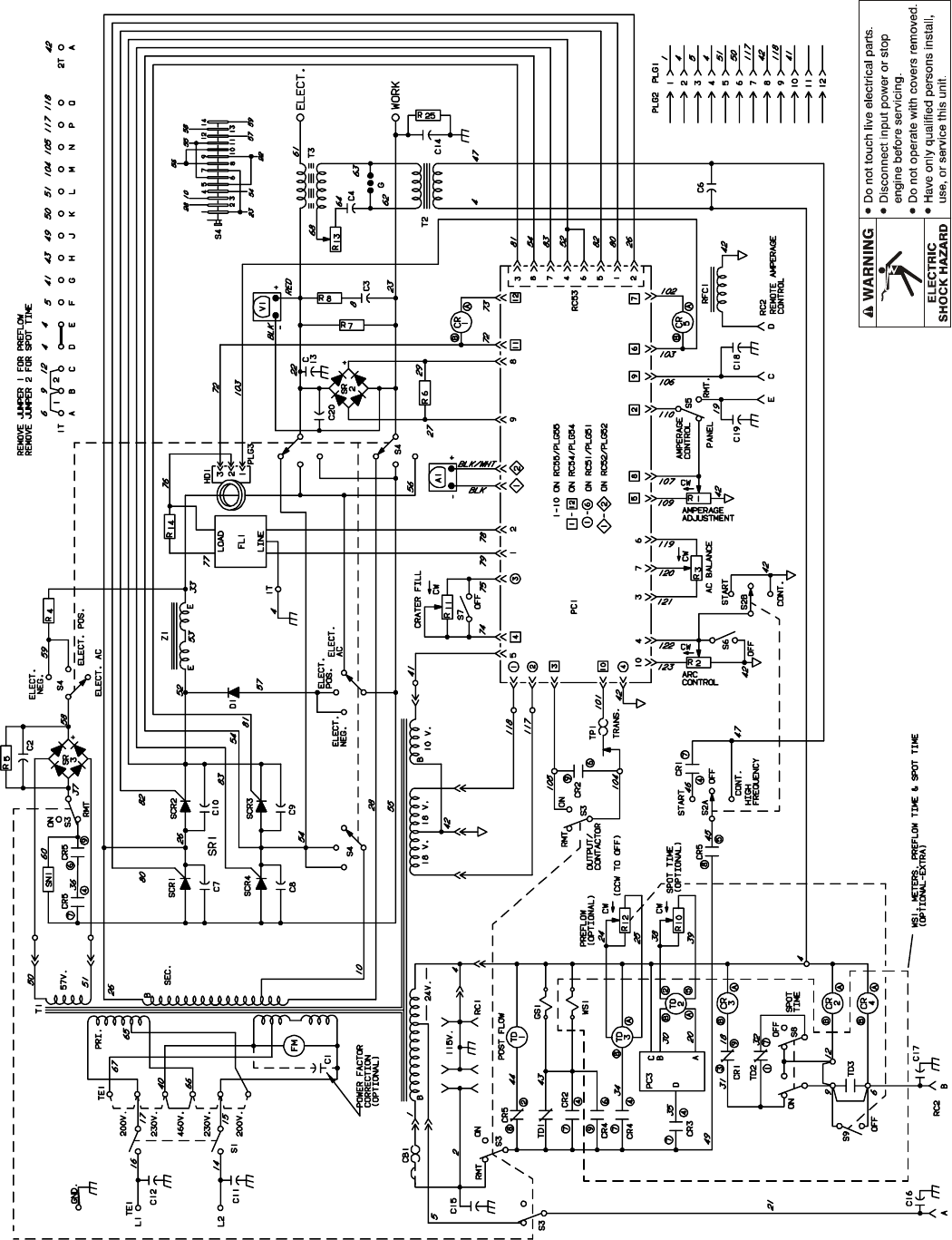
TM-353 Page 51Syncrowave 250
Figure 9-10. Circuit Diagram For Syncrowave 250 Effective With Serial No. KB110695 Thru KC252675
SC-148 144
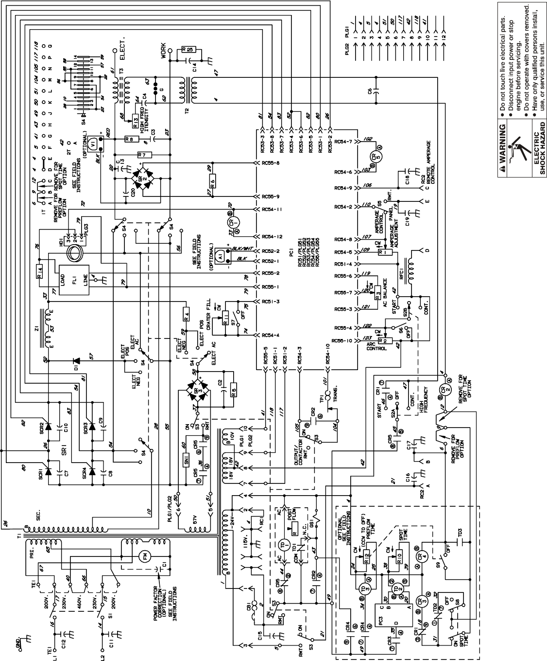
TM-353 Page 52 Syncrowave 250
Figure 9-11. Circuit Diagram For Syncrowave 250 Effective With Serial No. KC252676 Thru KG029204
SC-154 649-C
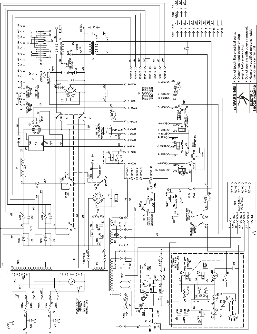
TM-353 Page 53Syncrowave 250
Figure 9-12. Circuit Diagram For Syncrowave 250 Effective With Serial No. KG029205 Thru KG062109
SC-178 835
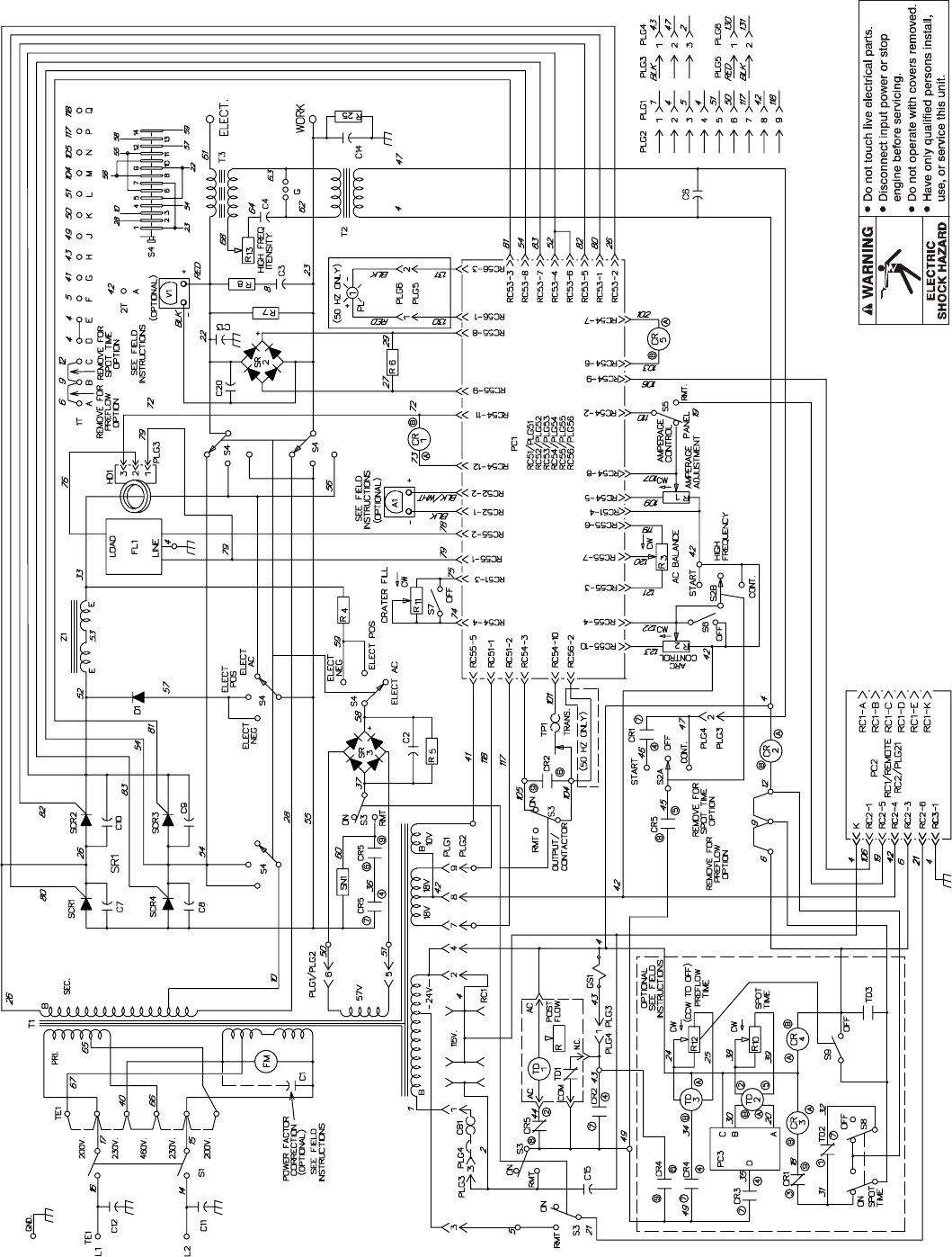
TM-353 Page 54 Syncrowave 250
Figure 9-13. Circuit Diagram For Syncrowave 250 Effective With Serial No. KG062110 Thru KG170300
SC-179 303-A
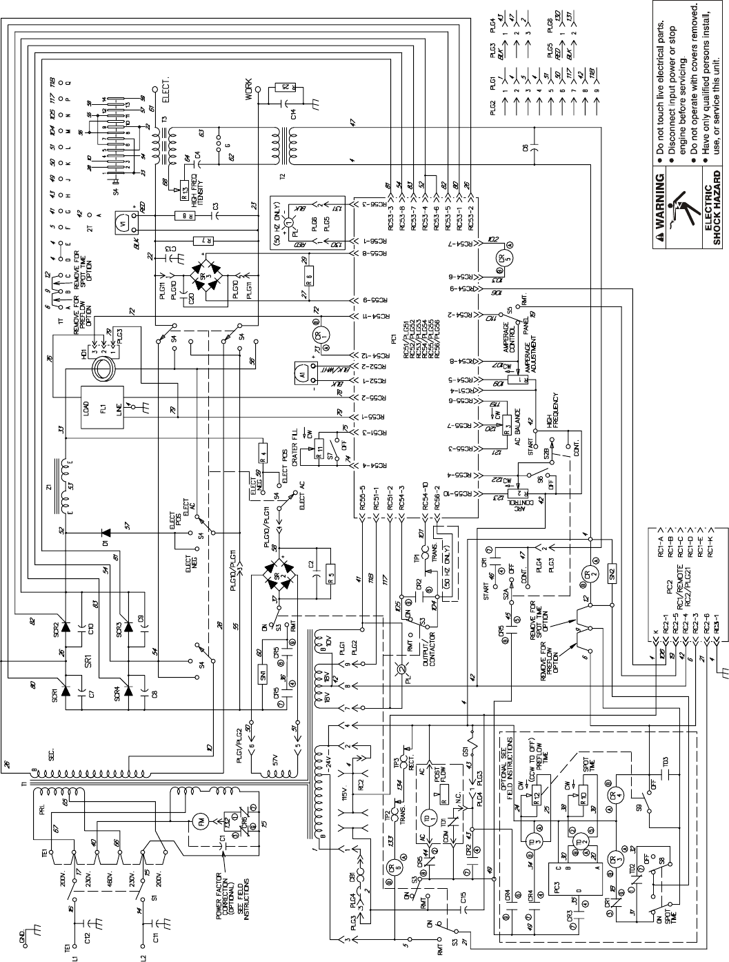
TM-353 Page 55Syncrowave 250
Figure 9-14. Circuit Diagram For Syncrowave 250 Effective With Serial No. KG170301 Thru KH526230
SC-181 109-E
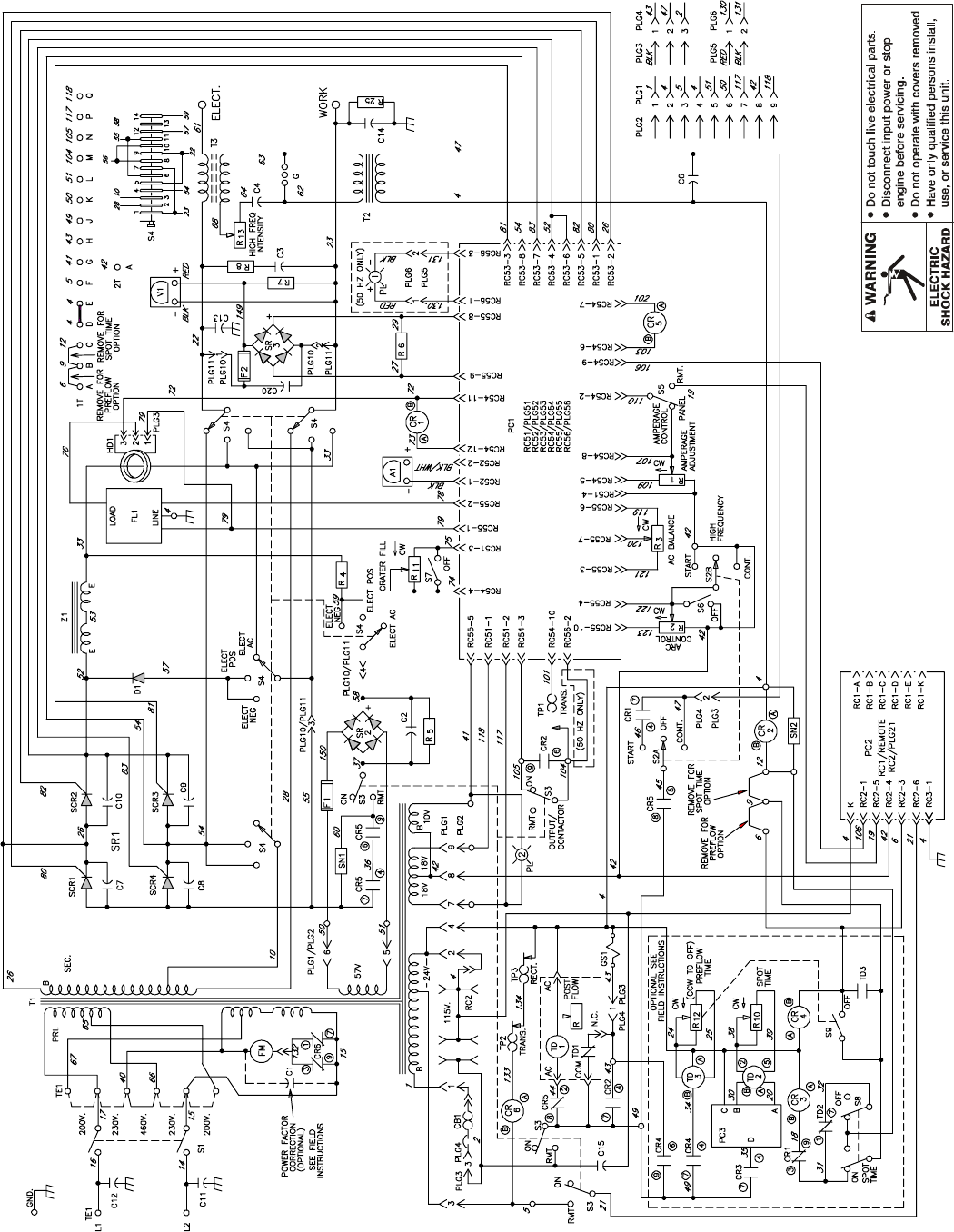
TM-353 Page 56 Syncrowave 250
SC-188 161-A
Figure 9-15. Circuit Diagram For Syncrowave 250 Effective With Serial No. KH526231 And Following

TM-353 Page 57Syncrowave 250
Notes
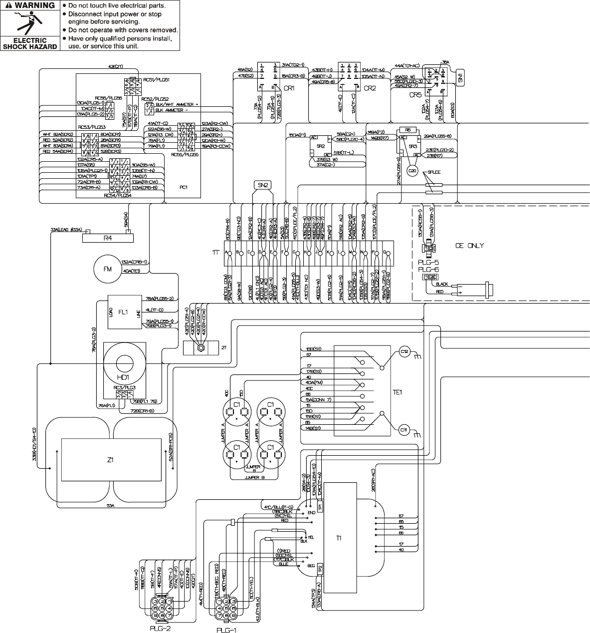
TM-353 Page 58 Syncrowave 250
Figure 9-16. Wiring Diagram For Syncrowave 250 Effective With Serial No. KH526231 And Following
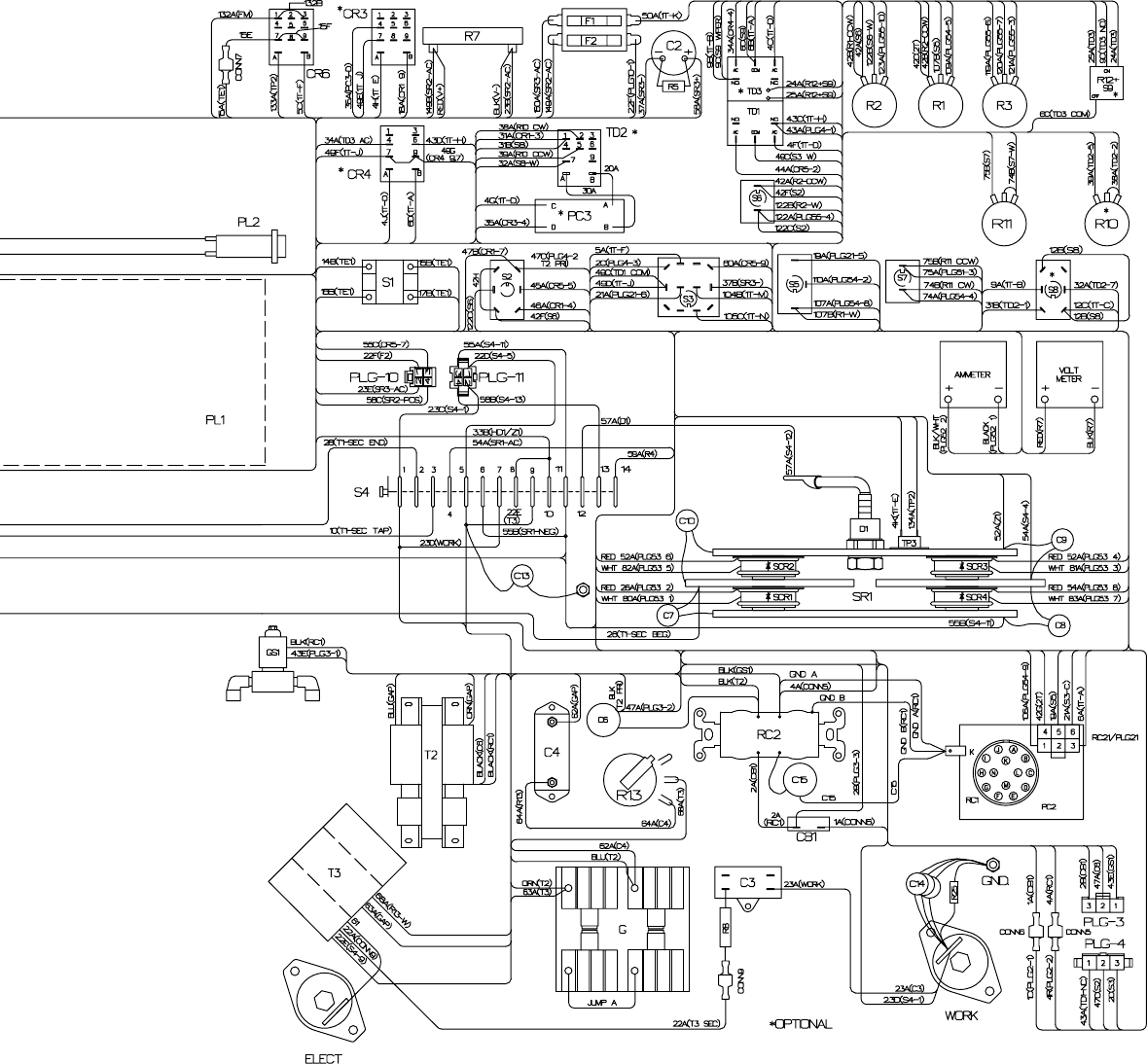
TM-353 Page 59Syncrowave 250
SD-188 162-A
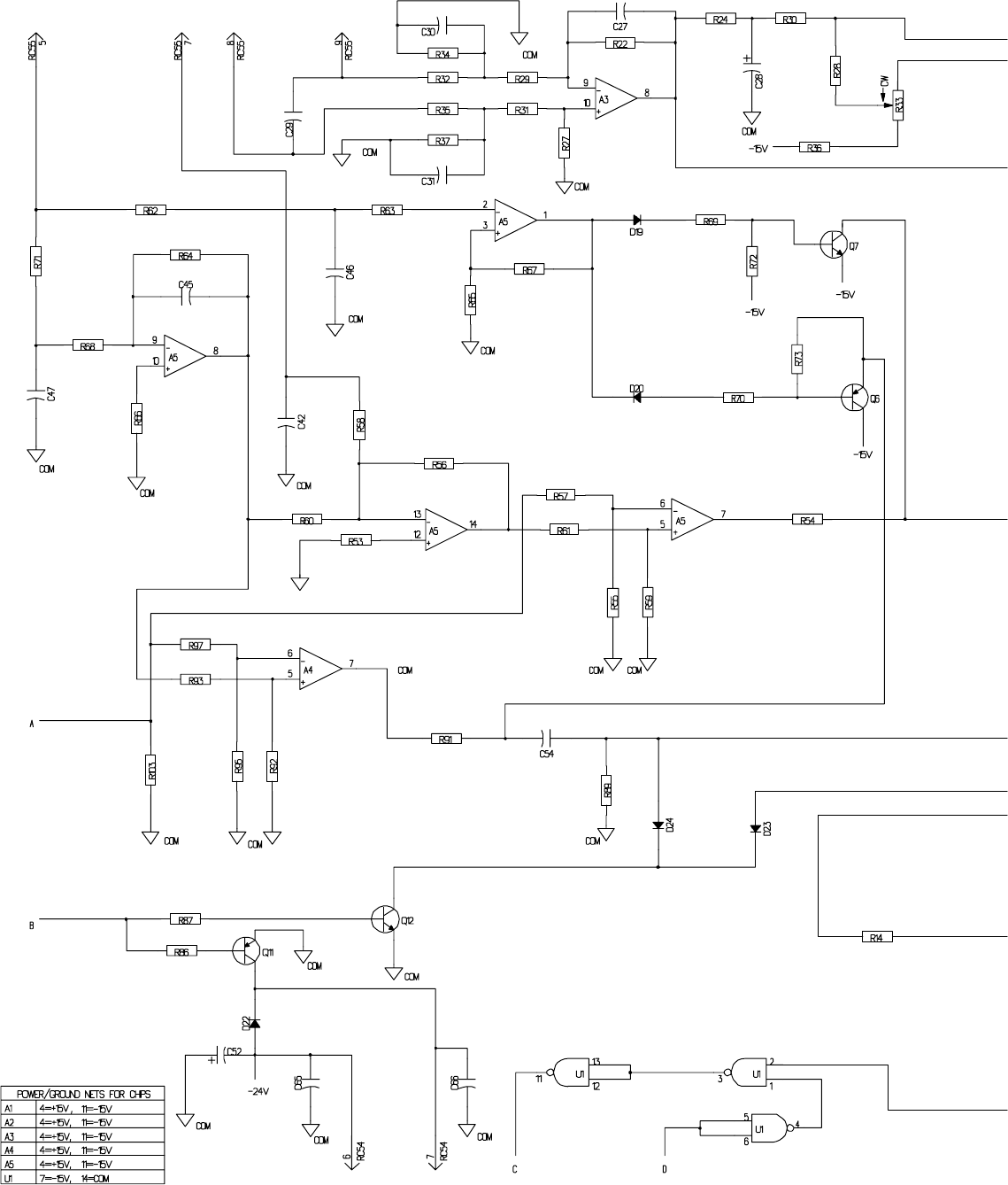
TM-353 Page 60 Syncrowave 250
Figure 9-17. Circuit Diagram For Control Board PC1 Effective With
Serial No. KH508255 And Following (Part 1 Of 2)
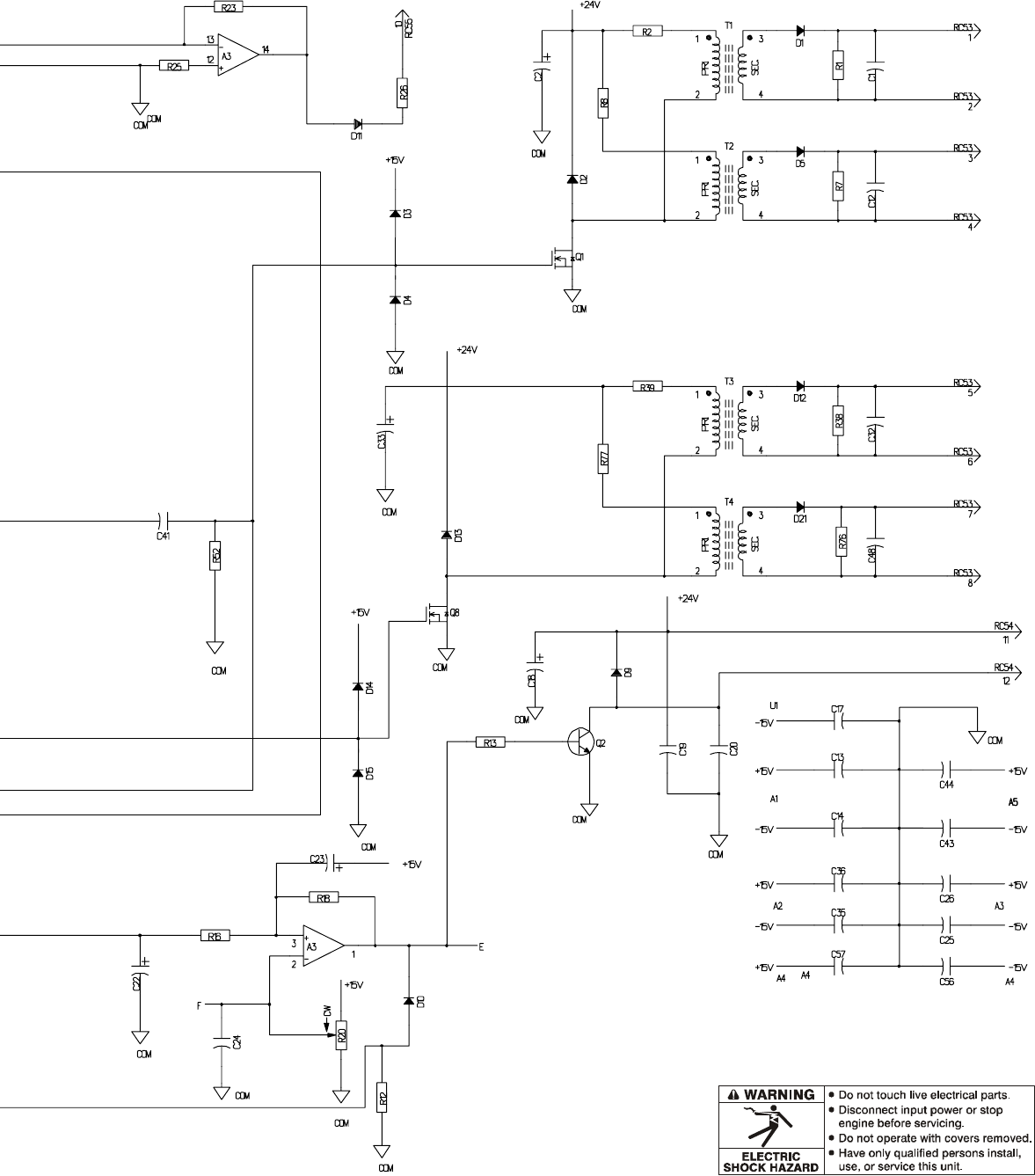
TM-353 Page 61Syncrowave 250
SD-187 644 (1 of 2)
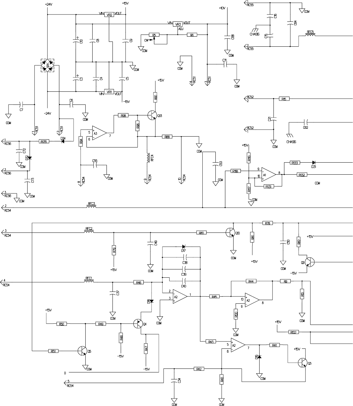
TM-353 Page 62 Syncrowave 250
Figure 9-18. Circuit Diagram For Control Board PC1 Effective With
Serial No. KH508255 And Following (Part 2 Of 2)
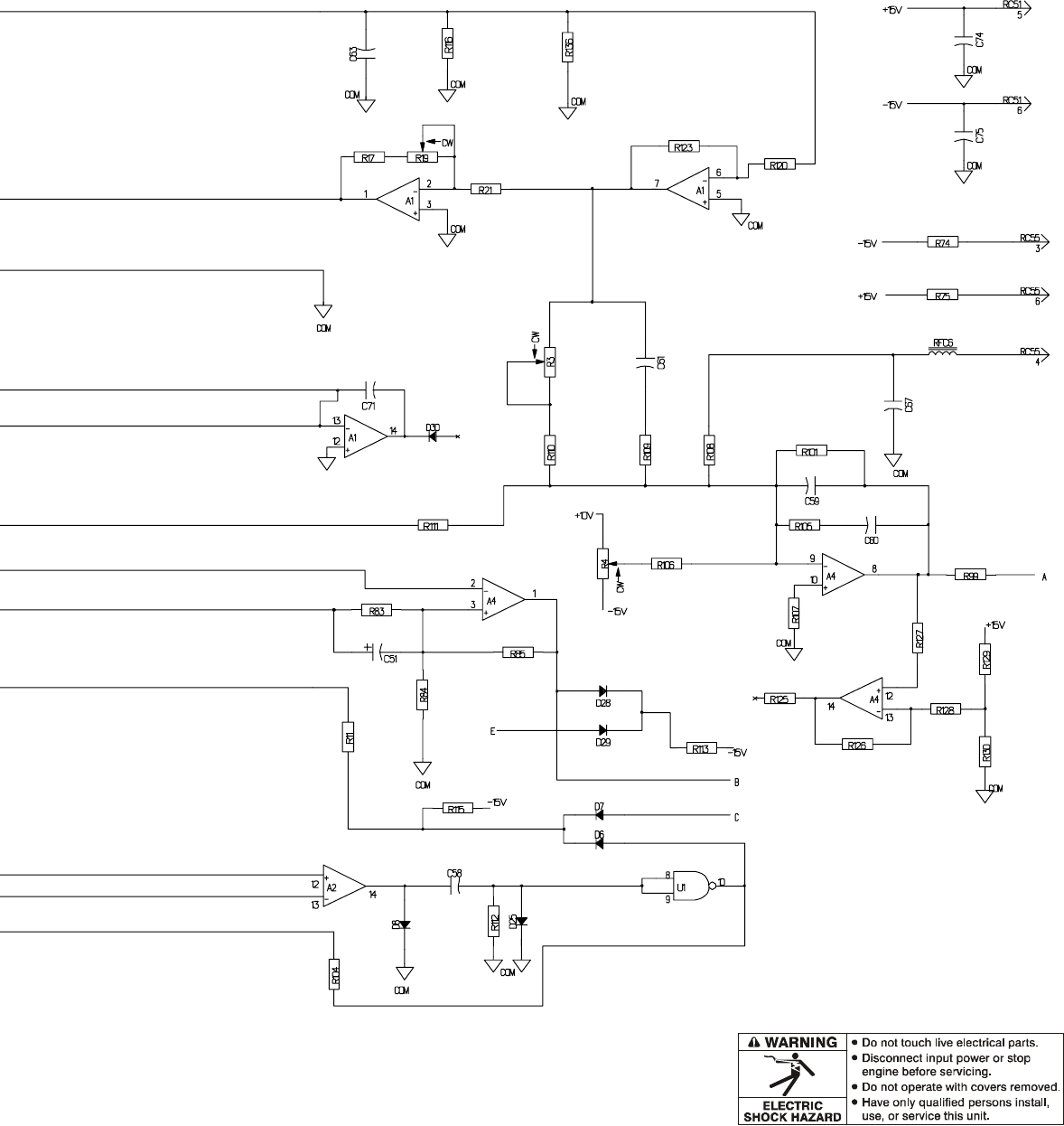
TM-353 Page 63Syncrowave 250
SD-187 644 (2 of 2)
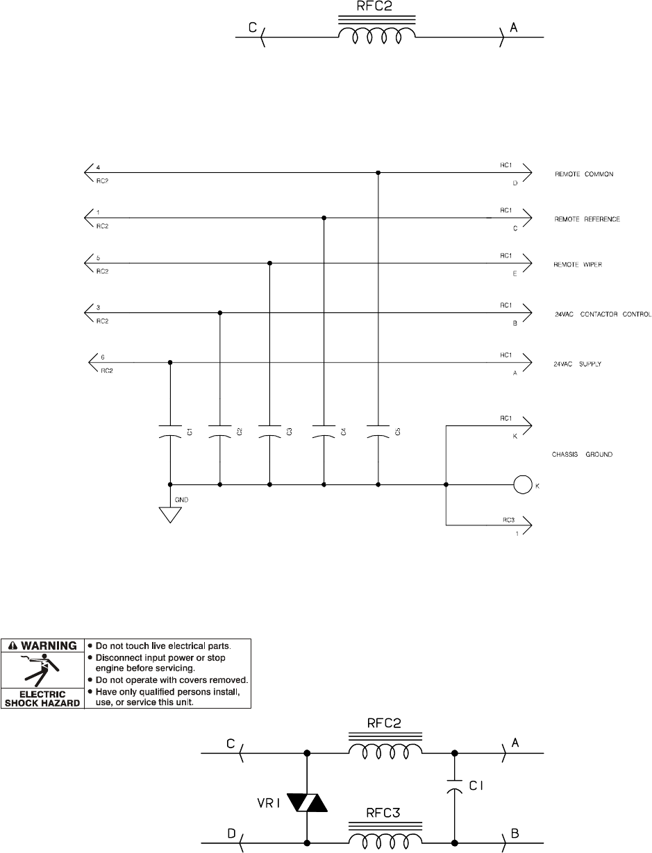
TM-353 Page 64 Syncrowave 250
Figure 9-19. Circuit Diagram For RFC Board PC2 Effective With Serial No. JJ365634 Thru KB010829
Figure 9-20. Circuit Diagram For Remote 14 Filter Board PC2
Effective With Serial No. KF959379 And Following
SA-120 872
SA-121 282
Figure 9-21. Circuit Diagram For Optional Snubber Board PC3
Effective With Serial No. JJ351865 And Following
SA-158 763
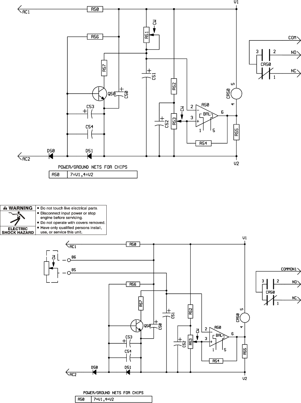
TM-353 Page 65Syncrowave 250
SA-045 288-D
Figure 9-22. Circuit Diagram For Optional Preflow Timer Board TD3
Effective With Serial No. JJ339876 And Following
SA-044 725-C
Figure 9-23. Circuit Diagram For Postflow Timer Board TD1
Effective With Serial No. JJ339876 And Following

TM-353 Page 66 Syncrowave 250
Notes
Syncrowave 250
Processes
60 Hz, 50 Hz
R
TM-353E January 2001
Eff. w/Serial Number JJ339876
Description
TIG (GTAW) Welding
Stick (SMAW) Welding
Arc Welding Power Source
Visit our website at
www.MillerWelds.com
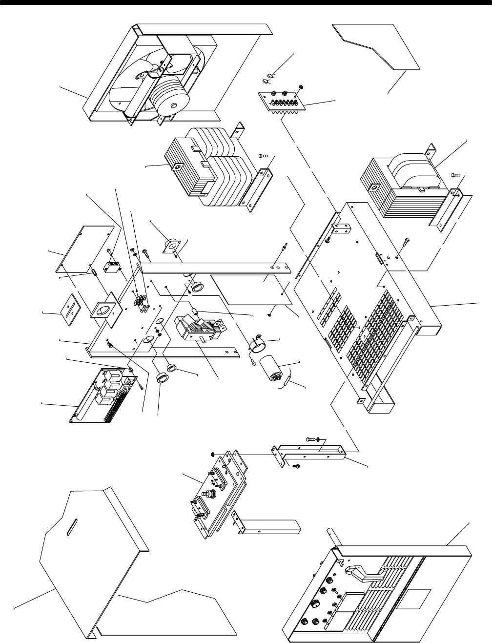
TM-353 Page 68 Syncrowave 250
SECTION 10 – PARTS LIST
Figure 10-1. Main Assembly ST-120 135-R
.Hardware is common and
not available unless listed.
1
2–Fig.10-3
3
4
5
6
7–Fig.10-5
89
10
11 12
13
30
31
14
15
16
17–Fig.10-4
18
19
20
21
22
23
24
25
26
27
28
29–Fig.10-2

TM-353 Page 69Syncrowave 250
Figure 10-1. Main Assembly
Description Quantity
Part
No.
Dia.
Mkgs.
Item
No.
1 114 741 COVER, top (Prior to KG170301) 1. . . . . . . . . . . . . . . . . . . . . . . . . . . . . . . . . . . . . . . . . . . . . . . . . . . . . .
1 182 605 COVER, top (Eff w/KG170301) 1. . . . . . . . . . . . . . . . . . . . . . . . . . . . . . . . . . . . . . . . . . . . . . . . . . . . . . . .
2 SR1 181 106 RECTIFIER, si diode (Fig 10-3) 1. . . . . . . . . . . . . . . . . . . . . . . . . . . . . . . . . . . . . . . . . . . . . . . . . . .
3 S4 112 630 SWITCH, plrty/changeover (Prior to KA759476) 1. . . . . . . . . . . . . . . . . . . . . . . . . . . . . . . . . . . . . .
3 S4 133 061 SWITCH, plrty/changeover (Eff w/KA759476) 1. . . . . . . . . . . . . . . . . . . . . . . . . . . . . . . . . . . . . . . .
PLG10 164 899 CONNECTOR & SOCKETS 1. . . . . . . . . . . . . . . . . . . . . . . . . . . . . . . . . . . . . . . . . . . . . . . . . . . . .
PLG11 168 809 CONNECTOR & SOCKETS 1. . . . . . . . . . . . . . . . . . . . . . . . . . . . . . . . . . . . . . . . . . . . . . . . . . . . . .
C13 155 082 CAPACITOR, cer disc. .003 200VAC (Prior to JK690987) 1. . . . . . . . . . . . . . . . . . . . . . . . . . . . . .
C13 132 433 CAPACITOR, cer disc. .05uf 500VDC (Eff w/JK690987) 1. . . . . . . . . . . . . . . . . . . . . . . . . . . . . . . .
4 057 357 BUSHING, snap-in nyl .937 ID x 1.125mtg hole 1. . . . . . . . . . . . . . . . . . . . . . . . . . . . . . . . . . . . . . . . . .
5 010 494 BUSHING, snap-in nyl 1.375 ID x1.750mtg hole 2. . . . . . . . . . . . . . . . . . . . . . . . . . . . . . . . . . . . . . . . . .
6 110 375 STAND-OFF SUPPORT, PC card No. 6 screw (Prior to KG170301) 3. . . . . . . . . . . . . . . . . . . . . . . .
6 134 201 STAND-OFF SUPPORT, PC card No. 6 screw (Eff w/KG170301) 3. . . . . . . . . . . . . . . . . . . . . . . . . .
7 Fig 10-4 PANEL, mtg components 1. . . . . . . . . . . . . . . . . . . . . . . . . . . . . . . . . . . . . . . . . . . . . . . . . . . . . . . . . . . . .
8 083 147 GROMMET, screw No. 8/10 panel hole .312sq .500 high 4. . . . . . . . . . . . . . . . . . . . . . . . . . . . . . . . . .
9 114 754 FRAME, lifting (Prior to KG170301) 1. . . . . . . . . . . . . . . . . . . . . . . . . . . . . . . . . . . . . . . . . . . . . . . . . . . .
9 181 101 FRAME, lifting (Eff w/KG170301) 1. . . . . . . . . . . . . . . . . . . . . . . . . . . . . . . . . . . . . . . . . . . . . . . . . . . . . .
10 026 627 GASKET, lift eye 1. . . . . . . . . . . . . . . . . . . . . . . . . . . . . . . . . . . . . . . . . . . . . . . . . . . . . . . . . . . . . . . . . . .
11 070 026 STAND-OFF, 6-32 x .437 lg 1. . . . . . . . . . . . . . . . . . . . . . . . . . . . . . . . . . . . . . . . . . . . . . . . . . . . . . . . .
12 PC1 117 981 CIRCUIT CARD, control (Prior to JJ389988) (Fig 10-5) 1. . . . . . . . . . . . . . . . . . . . . . . . . . . . .
12 PC1 138 058 CIRCUIT CARD, control (Eff w/JJ389988 thru KB110694) (Fig 10-5) 1. . . . . . . . . . . . . . . . .
12 PC1 180 014 CIRCUIT CARD, control (Eff w/ KB110695 thru KG060803) 1. . . . . . . . . . . . . . . . . . . . . . . . .
12 PC1 187 642 CIRCUIT CARD, control (Eff w/KG060804) 1. . . . . . . . . . . . . . . . . . . . . . . . . . . . . . . . . . . . . . .
PLG51 115 093 CONNECTOR PLUG & SOCKETS 1. . . . . . . . . . . . . . . . . . . . . . . . . . . . . . . . . . . . . . . . . . . . . . .
PLG54 130 203 CONNECTOR PLUG & SOCKETS 1. . . . . . . . . . . . . . . . . . . . . . . . . . . . . . . . . . . . . . . . . . . . . . .
PLG55 115 091 CONNECTOR PLUG & SOCKETS 1. . . . . . . . . . . . . . . . . . . . . . . . . . . . . . . . . . . . . . . . . . . . . . .
13 R14 138 105 RESISTOR, (Eff w/KB110695 thru KG062110) 1. . . . . . . . . . . . . . . . . . . . . . . . . . . . . . . . . . . .
13 FL1 084 171 FILTER, line power 115/250V 1. . . . . . . . . . . . . . . . . . . . . . . . . . . . . . . . . . . . . . . . . . . . . . . . . . .
14 HD1 156 313 TRANSDUCER, current 300A (Eff w/KB110695) 1. . . . . . . . . . . . . . . . . . . . . . . . . . . . . . . . . .
PLG3 130 204 CONNECTOR & SOCKETS, (Eff w/KB110695) 1. . . . . . . . . . . . . . . . . . . . . . . . . . . . . . . . . . . . .
15 073 756 STAND-OFF, 6-32 x .625 lg (Eff w/KB110695) 2. . . . . . . . . . . . . . . . . . . . . . . . . . . . . . . . . . . . . . . . .
16 Z1 114 826 REACTOR 1. . . . . . . . . . . . . . . . . . . . . . . . . . . . . . . . . . . . . . . . . . . . . . . . . . . . . . . . . . . . . . . . . . . .
17 Fig 10-4 PANEL, rear w/components 1. . . . . . . . . . . . . . . . . . . . . . . . . . . . . . . . . . . . . . . . . . . . . . . . . . . . . . . . .
109 035 LABEL, warning electric shock can kill etc 1. . . . . . . . . . . . . . . . . . . . . . . . . . . . . . . . . . . . . . . . . . . . . . . . .
18 C11,12 111 634 CAPACITOR 1. . . . . . . . . . . . . . . . . . . . . . . . . . . . . . . . . . . . . . . . . . . . . . . . . . . . . . . . . . . . . .
172 078 BRACKET, mtg primary board (Eff w/KE727074) 1. . . . . . . . . . . . . . . . . . . . . . . . . . . . . . . . . . . . . . . . . . .
19 TE1 034 587 TERMINAL ASSEMBLY, pri (consisting of) 1. . . . . . . . . . . . . . . . . . . . . . . . . . . . . . . . . . . . . . .
601 835 NUT, brs hex 10-32 12. . . . . . . . . . . . . . . . . . . . . . . . . . . . . . . . . . . . . . . . . . . . . . . . . . . . . . . . . . . . . . . . . . . .
601 836 NUT, brs hex .250-20 jam hvy 4. . . . . . . . . . . . . . . . . . . . . . . . . . . . . . . . . . . . . . . . . . . . . . . . . . . . . . . . . . . .
010 915 WASHER, flat brs .250 ID x .625 OD x .031thk 4. . . . . . . . . . . . . . . . . . . . . . . . . . . . . . . . . . . . . . . . . . . . .
083 426 TERMINAL BOARD, primary 1. . . . . . . . . . . . . . . . . . . . . . . . . . . . . . . . . . . . . . . . . . . . . . . . . . . . . . . . . . . .
038 888 STUD, primary board brs .250-20 x 1.500 2. . . . . . . . . . . . . . . . . . . . . . . . . . . . . . . . . . . . . . . . . . . . . . . . .
010 913 WASHER, flat brs .218 ID x 460 OD x .031thk 6. . . . . . . . . . . . . . . . . . . . . . . . . . . . . . . . . . . . . . . . . . . . .
038 887 STUD, primary board brs 10-32 x 1.375 6. . . . . . . . . . . . . . . . . . . . . . . . . . . . . . . . . . . . . . . . . . . . . . . . . . .
038 618 LINK, jumper term bd pri 2. . . . . . . . . . . . . . . . . . . . . . . . . . . . . . . . . . . . . . . . . . . . . . . . . . . . . . . . . . . . . . . .
20 +114 751 PANEL, side (Prior to KG170301) 2. . . . . . . . . . . . . . . . . . . . . . . . . . . . . . . . . . . . . . . . . . . . . . . . . . .
20 +181 097 PANEL, side (Eff w/KG170301 thru KG181270) 2. . . . . . . . . . . . . . . . . . . . . . . . . . . . . . . . . . . . . . .
20 +182 606 PANEL, side (Eff w/KG181271 and on) 2. . . . . . . . . . . . . . . . . . . . . . . . . . . . . . . . . . . . . . . . . . . . . .
21 T1 115 097 TRANSFORMER, pwr main 200/230/460 (Prior to KA877025) 1. . . . . . . . . . . . . . . . . . . . . . .
21 T1 138 171 TRANSFORMER, pwr main 200/230/460 (Eff w/KA877025 thru KG082621) 1. . . . . . . . . . .
21 T1 180 674 TRANSFORMER, pwr main 200/230/460 (Eff w/KG082622) 1. . . . . . . . . . . . . . . . . . . . . . . . .
21 T1 138 175 TRANSFORMER, pwr main (220/380/415 (Prior to KG082622) 1. . . . . . . . . . . . . . . . . . . . . .
21 T1 180 673 TRANSFORMER, pwr main 220/380/415 (Eff w/KG082622) 1. . . . . . . . . . . . . . . . . . . . . . . . .
21 T1 121 161 TRANSFORMER, pwr main 230/460/575 (Prior to KA877025) 1. . . . . . . . . . . . . . . . . . . . . . .
21 T1 138 172 TRANSFORMER, pwr main 230/460/575 (Eff w/KA877025 thru KG082621) 1. . . . . . . . . . .
21 T1 180 672 TRANSFORMER, pwr main 230/460/575 (Eff w/KG082622) 1. . . . . . . . . . . . . . . . . . . . . . . . .
21 T1 191 887 TRANSFORMER, pwr main 260/380/520 1. . . . . . . . . . . . . . . . . . . . . . . . . . . . . . . . . . . . . . . . .
TP1 020 520 THERMOSTAT, NC (included w/transformer) 1. . . . . . . . . . . . . . . . . . . . . . . . . . . . . . . . . . . . . . . . .
TP2 168 891 THERMOSTAT, NC (Eff w/KG170301) 1. . . . . . . . . . . . . . . . . . . . . . . . . . . . . . . . . . . . . . . . . . . . . . .

TM-353 Page 70 Syncrowave 250
Figure 10-1. Main Assembly (Continued)
Description Quantity
Part
No.
Dia.
Mkgs.
Item
No.
22 114 755 BASE, (Prior to KE727074) 1. . . . . . . . . . . . . . . . . . . . . . . . . . . . . . . . . . . . . . . . . . . . . . . . . . . . . . . . . .
22 170 748 BASE, (Eff w/KE727074 thru KF959176) 1. . . . . . . . . . . . . . . . . . . . . . . . . . . . . . . . . . . . . . . . . . . . . .
22 171 677 BASE, (Eff w/KF959177) 1. . . . . . . . . . . . . . . . . . . . . . . . . . . . . . . . . . . . . . . . . . . . . . . . . . . . . . . . . . . .
23 157 196 INSULATOR, upright (Eff w/KC307050) 1. . . . . . . . . . . . . . . . . . . . . . . . . . . . . . . . . . . . . . . . . . . . . . .
24 010 199 TUBING, stl .500 OD x 17ga x 1 2. . . . . . . . . . . . . . . . . . . . . . . . . . . . . . . . . . . . . . . . . . . . . . . . . . . . .
25 108 105 CLAMP, capacitor 2.500dia 1. . . . . . . . . . . . . . . . . . . . . . . . . . . . . . . . . . . . . . . . . . . . . . . . . . . . . . . . . .
26 C2 031 668 CAPACITOR, elctlt 4000uf 100VDC 1. . . . . . . . . . . . . . . . . . . . . . . . . . . . . . . . . . . . . . . . . . . . . .
27 R5 117 803 RESISTOR, WW fxd 10W 1K ohm 1. . . . . . . . . . . . . . . . . . . . . . . . . . . . . . . . . . . . . . . . . . . . . . .
28 114 722 BRACKET, mtg rectifier 2. . . . . . . . . . . . . . . . . . . . . . . . . . . . . . . . . . . . . . . . . . . . . . . . . . . . . . . . . . . . .
29 Fig 10-2 PANEL, front w/components 1. . . . . . . . . . . . . . . . . . . . . . . . . . . . . . . . . . . . . . . . . . . . . . . . . . . . . . . . .
30 098 376 FUSE, holder (Eff w/KH526231) 1. . . . . . . . . . . . . . . . . . . . . . . . . . . . . . . . . . . . . . . . . . . . . . . . . . . . .
31 F1,2 085 874 FUSE, mintr gl slo-blo 10A (Eff w/KH526231) 1. . . . . . . . . . . . . . . . . . . . . . . . . . . . . . . . . . . . .
092 368 TUBING, stl .250 ID x 16ga x 3 (Prior to JK682714) 1. . . . . . . . . . . . . . . . . . . . . . . . . . . . . . . . . . . . . . . .
130 764 TUBING, stl .250 ID x 16ga wall x 1.500 (Eff w/JK682714) 1. . . . . . . . . . . . . . . . . . . . . . . . . . . . . . . . . .
+When ordering a component originally displaying a precautionary label, the label should also be ordered.
BE SURE TO PROVIDE MODEL AND SERIAL NUMBER WHEN ORDERING REPLACEMENT PARTS.

TM-353 Page 71Syncrowave 250
1
2
ST-120 088-G
3
4 5 6
7
4
8
9
10
12
13
Includes
Item 26
11
14
15
16
17
18
19
23
25
26
27 1
21 20
28
29
2224
Figure 10-6
Figure 10-2. Panel, Front w/Components
Figure 10-2. Panel, Front w/Components (Fig 10-1 Item 29)
Description Quantity
Part
No.
Dia.
Mkgs.
Item
No.
1 097 922 KNOB, pointer 3. . . . . . . . . . . . . . . . . . . . . . . . . . . . . . . . . . . . . . . . . . . . . . . . . . . . . . . . . . . . . . . . . . . .
2 NAMEPLATE, (order by model & serial number) 1. . . . . . . . . . . . . . . . . . . . . . . . . . . . . . . . . . . . . . . . . . . . . . . .
3 109 013 BUSHING, snap-in nyl .375 ID x .562mtg hole 1. . . . . . . . . . . . . . . . . . . . . . . . . . . . . . . . . . . . . . . . .
4 S6,7 089 085 SWITCH, tgl SPST 20A 125VAC (Prior to KF988252) 2. . . . . . . . . . . . . . . . . . . . . . . . . . . .
4 S6,7 176 882 SWITCH, tgl SPST 20A 125VAC (Eff w/KF988252) 2. . . . . . . . . . . . . . . . . . . . . . . . . . . . . .
107 983 BLANK, snap-in nyl .500mtg hole 1. . . . . . . . . . . . . . . . . . . . . . . . . . . . . . . . . . . . . . . . . . . . . . . . . . . . . . .
057 359 BLANK, snap-in nyl .375mtg hole 2. . . . . . . . . . . . . . . . . . . . . . . . . . . . . . . . . . . . . . . . . . . . . . . . . . . . . . .
5 R3 030 109 POTENTIOMETER, C sltd sft 1/T 2W 5000 ohm 1. . . . . . . . . . . . . . . . . . . . . . . . . . . . . . . . . .
6 R11 030 684 POTENTIOMETER, C sltd sft 1/T 2W 5 meg ohm 1. . . . . . . . . . . . . . . . . . . . . . . . . . . . . . . .
7 R1,2 035 897 POTENTIOMETER, C sltd sft 1/T 2W 1000 ohm 2. . . . . . . . . . . . . . . . . . . . . . . . . . . . . . . .
8 S5 011 609 SWITCH, tgl SPDT 15A 125VAC 1. . . . . . . . . . . . . . . . . . . . . . . . . . . . . . . . . . . . . . . . . . . . . . . . .
9 S3 052 769 SWITCH, tgl 4PDT 15A 125VAC 1. . . . . . . . . . . . . . . . . . . . . . . . . . . . . . . . . . . . . . . . . . . . . . . .
10 S2 011 610 SWITCH, tgl SPDT 15A 125VAC (Prior to JJ503984) 1. . . . . . . . . . . . . . . . . . . . . . . . . . . . . . . .
10 S2 088 409 SWITCH, tgl 2PDT 15A 125VAC (Eff w/JJ503984) 1. . . . . . . . . . . . . . . . . . . . . . . . . . . . . . . . .
11 TD1 052 192 TIMER, delay on make - postflow (consisting of) 1. . . . . . . . . . . . . . . . . . . . . . . . . . . . . . . . .
12 039 449 BRACKET, mtg - circuit card 1. . . . . . . . . . . . . . . . . . . . . . . . . . . . . . . . . . . . . . . . . . . . . . . . . . . . . . . .

TM-353 Page 72 Syncrowave 250
Figure 10-2. Panel, Front w/ Components (Continued)
Description Quantity
Part
No.
Dia.
Mkgs.
Item
No.
13 044 723 CIRCUIT CARD, postflow 1. . . . . . . . . . . . . . . . . . . . . . . . . . . . . . . . . . . . . . . . . . . . . . . . . . . . . . . . . . .
14 S1 045 834 SWITCH, tgl DPST 60A 600VAC (Prior to KA759476) 1. . . . . . . . . . . . . . . . . . . . . . . . . . . . . .
14 S1 128 757 SWITCH, tgl DPST 60A 600VAC (Eff w/KA759476) 1. . . . . . . . . . . . . . . . . . . . . . . . . . . . . . . .
15 106 398 PIN, spring CS .156 x .625 1. . . . . . . . . . . . . . . . . . . . . . . . . . . . . . . . . . . . . . . . . . . . . . . . . . . . . . . . .
16 114 721 SHAFT, extension switch (Prior to KA759476) 1. . . . . . . . . . . . . . . . . . . . . . . . . . . . . . . . . . . . . . . . . .
16 133 276 EXTENSION, handle switch (Eff w/KA759476 thru KF959378) 1. . . . . . . . . . . . . . . . . . . . . . . . . .
16 171 420 EXTENSION, handle switch (Eff w/KF959379) 1. . . . . . . . . . . . . . . . . . . . . . . . . . . . . . . . . . . . . . . .
17 164 481 PANEL, front (Prior to KF959379) 1. . . . . . . . . . . . . . . . . . . . . . . . . . . . . . . . . . . . . . . . . . . . . . . . . . .
17 169 476 PANEL, front (Eff w/KF959379 thru KG170300) 1. . . . . . . . . . . . . . . . . . . . . . . . . . . . . . . . . . . . . . .
17 181 096 PANEL, front (Eff w/KG170301) 1. . . . . . . . . . . . . . . . . . . . . . . . . . . . . . . . . . . . . . . . . . . . . . . . . . . . .
18 CONTROL PANEL, lower front (Fig 10-6) 1. . . . . . . . . . . . . . . . . . . . . . . . . . . . . . . . . . . . . . . . . . . . . . . . . . . . . .
19 128 230 LABEL, warning electric shock etc 1. . . . . . . . . . . . . . . . . . . . . . . . . . . . . . . . . . . . . . . . . . . . . . . . . . .
19 134 327 LABEL, warning electric shock etc CE 1. . . . . . . . . . . . . . . . . . . . . . . . . . . . . . . . . . . . . . . . . . . . . . . .
20 +114 759 DOOR, access front (Prior to KG170301) 1. . . . . . . . . . . . . . . . . . . . . . . . . . . . . . . . . . . . . . . . . . . .
20 +181 589 DOOR, access front (Eff w/KG170301) 1. . . . . . . . . . . . . . . . . . . . . . . . . . . . . . . . . . . . . . . . . . . . . .
605 583 CATCH, spring loaded door (Prior to KG170301) 1. . . . . . . . . . . . . . . . . . . . . . . . . . . . . . . . . . . . . . . . .
21 134 327 LABEL, warning general precautionary 1. . . . . . . . . . . . . . . . . . . . . . . . . . . . . . . . . . . . . . . . . . . . . . .
21 176 254 LABEL, warning general precautionary CE 1. . . . . . . . . . . . . . . . . . . . . . . . . . . . . . . . . . . . . . . . . . . .
22 PL2 157 958 LIGHT, ind wht lens 28V 1. . . . . . . . . . . . . . . . . . . . . . . . . . . . . . . . . . . . . . . . . . . . . . . . . . . . . . .
23 PL1 155 500 LED, yellow (50 Hz model) (Eff w/ KG060803) 1. . . . . . . . . . . . . . . . . . . . . . . . . . . . . . . . . . . .
PLG5 135 635 CONNECTOR & SOCKETS 1. . . . . . . . . . . . . . . . . . . . . . . . . . . . . . . . . . . . . . . . . . . . . . . . . . . . .
PLG6 131 054 CONNECTOR & SOCKETS 1. . . . . . . . . . . . . . . . . . . . . . . . . . . . . . . . . . . . . . . . . . . . . . . . . . . . .
24 010 647 PIN, spring CS .156 x 1.250 (Prior to KF959379) 1. . . . . . . . . . . . . . . . . . . . . . . . . . . . . . . . . . . . . .
24 169 136 PIN, handle (Eff w/KF959379) 1. . . . . . . . . . . . . . . . . . . . . . . . . . . . . . . . . . . . . . . . . . . . . . . . . . . . . . .
25 098 279 HANDLE, plrty/changeover switch (Prior to KF959379) 1. . . . . . . . . . . . . . . . . . . . . . . . . . . . . . . . .
25 169 135 HANDLE, switch (Eff w/KF959379) 1. . . . . . . . . . . . . . . . . . . . . . . . . . . . . . . . . . . . . . . . . . . . . . . . . .
26 052 370 KNOB, indicator 1. . . . . . . . . . . . . . . . . . . . . . . . . . . . . . . . . . . . . . . . . . . . . . . . . . . . . . . . . . . . . . . . . . .
27 097 924 KNOB, pointer 1. . . . . . . . . . . . . . . . . . . . . . . . . . . . . . . . . . . . . . . . . . . . . . . . . . . . . . . . . . . . . . . . . . . .
28 ♦115 920 METER, amp AC/DC 100MV 0-300 scale 1. . . . . . . . . . . . . . . . . . . . . . . . . . . . . . . . . . . . . . . . . . . .
29 ♦004 189 METER, volt AC/DC 0–100 scale 1. . . . . . . . . . . . . . . . . . . . . . . . . . . . . . . . . . . . . . . . . . . . . . . . . . .
+When ordering a component originally displaying a precautionary label, the label should also be ordered.
♦OPTIONAL
BE SURE TO PROVIDE MODEL AND SERIAL NUMBER WHEN ORDERING REPLACEMENT PARTS.
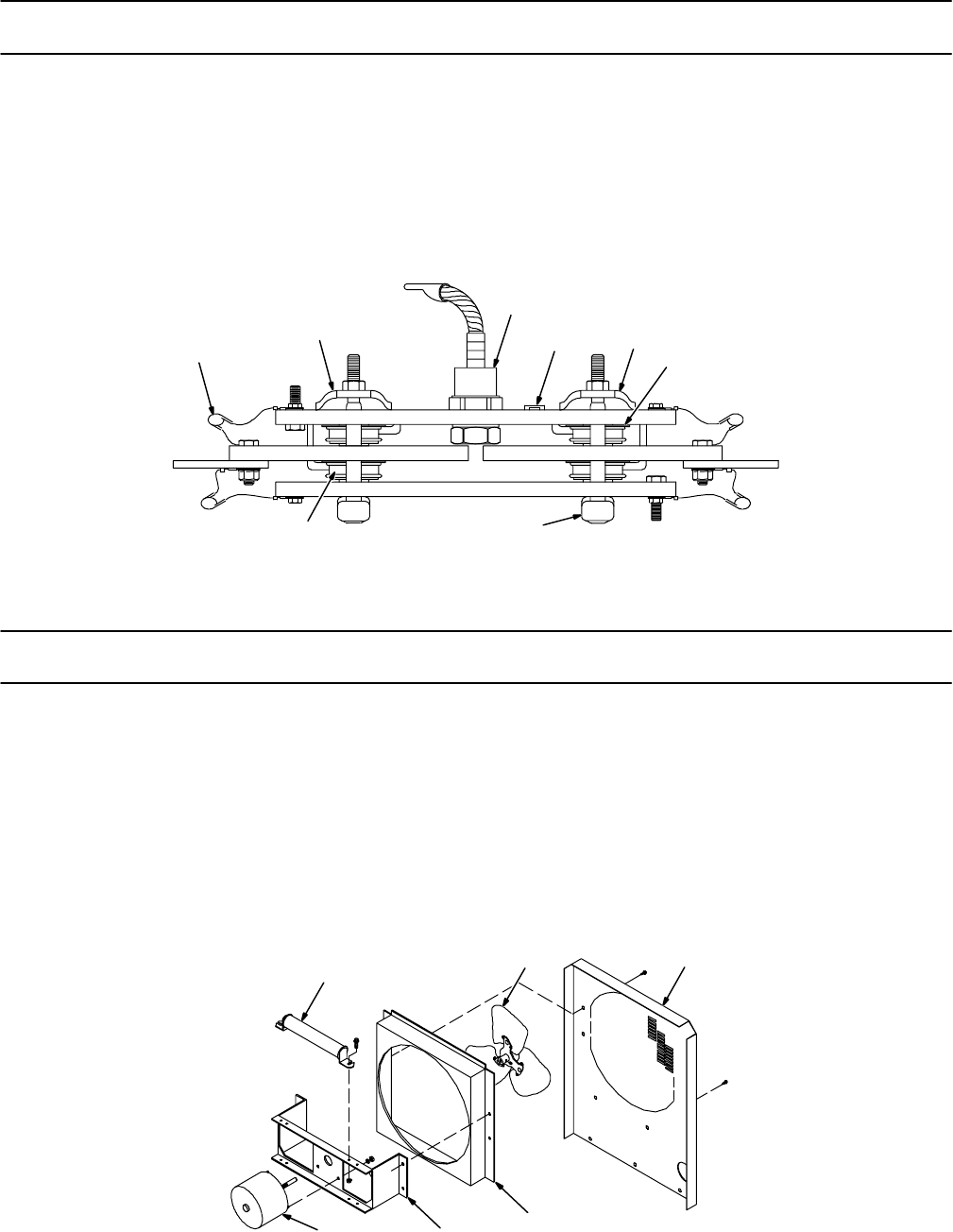
TM-353 Page 73Syncrowave 250
Figure 10-3. Rectifier, Si Diode (Fig 10-1 Item 2)
Description Quantity
Part
No.
Dia.
Mkgs.
Item
No.
1 C7-10 031 689 CAPACITOR, rectifier 4. . . . . . . . . . . . . . . . . . . . . . . . . . . . . . . . . . . . . . . . . . . . . . . . . . . . . . .
2 083 884 CLAMP, thyristor rectifier (Prior to KG023560) 2. . . . . . . . . . . . . . . . . . . . . . . . . . . . . . . . . . . . . . . . .
2 166 667 CLAMP, spring rectifier (Eff w/KG023560) 2. . . . . . . . . . . . . . . . . . . . . . . . . . . . . . . . . . . . . . . . . . . .
3 D1 037 956 DIODE, rect 275A 300V SP 1. . . . . . . . . . . . . . . . . . . . . . . . . . . . . . . . . . . . . . . . . . . . . . . . . . . . .
4 TP3 168 898 THERMOSTAT, NC open 125°C (Eff w/KG170301) 1. . . . . . . . . . . . . . . . . . . . . . . . . . . . . .
5 SCR1-4 115 114 THYRISTOR, SCR 300A 300V 4. . . . . . . . . . . . . . . . . . . . . . . . . . . . . . . . . . . . . . . . . . . . . . .
6 176 645 CLAMP, thyristor w/o thermostat (Eff w/KG023560) 2. . . . . . . . . . . . . . . . . . . . . . . . . . . . . . . . . . . .
6 173 714 CLAMP, thyristor with thermostat (Eff w/KG170030) 2. . . . . . . . . . . . . . . . . . . . . . . . . . . . . . . . . . . .
028 516 PIN, spring CS .125 x .250 2. . . . . . . . . . . . . . . . . . . . . . . . . . . . . . . . . . . . . . . . . . . . . . . . . . . . . . . . . . . .
PLG53 115 092 CONNECTOR & SOCKETS 1. . . . . . . . . . . . . . . . . . . . . . . . . . . . . . . . . . . . . . . . . . . . . . . . . . . .
12
3
5
5
2
ST-120 205-A
6
4
Figure 10-3. Rectifier, Si Diode
Figure 10-4. Panel, Rear w/Components (Fig 10-1 Item 17)
Description Quantity
Part
No.
Dia.
Mkgs.
Item
No.
1 R4 186 949 RESISTOR, WW fxd 175W 20 ohm 1. . . . . . . . . . . . . . . . . . . . . . . . . . . . . . . . . . . . . . . . . . . . . .
2 032 604 BLADE, fan 14 in 3 wing 19deg .375 bore CCW (Prior to KG198783) 1. . . . . . . . . . . . . . . . . . . . .
2 180 165 BLADE, fan 14 in 3 wing 19deg .375 bore CCW (Eff w/KG198783) 1. . . . . . . . . . . . . . . . . . . . . . .
3 114 752 PANEL, rear (Prior to KG170301) 1. . . . . . . . . . . . . . . . . . . . . . . . . . . . . . . . . . . . . . . . . . . . . . . . . . . . .
3 181 099 PANEL, rear (Eff w/KG170301) 1. . . . . . . . . . . . . . . . . . . . . . . . . . . . . . . . . . . . . . . . . . . . . . . . . . . . . .
4 131 361 CHAMBER, plenum 14 in (Prior to KG128812) 1. . . . . . . . . . . . . . . . . . . . . . . . . . . . . . . . . . . . . . . .
4 173 283 CHAMBER, plenum 14 in (Eff w/KG128812) (50 Hz only) 1. . . . . . . . . . . . . . . . . . . . . . . . . . . . . . .
5 124 274 BRACKET, mtg fan motor (Eff w/KG128812) 1. . . . . . . . . . . . . . . . . . . . . . . . . . . . . . . . . . . . . . . . . .
6 FM 116 190 MOTOR, 1/12 hp 230V 1550 RPM 50/60Hz 1.5A 1. . . . . . . . . . . . . . . . . . . . . . . . . . . . . . . . . . .
026 947 STAND-OFF, insul .250-20 x 1.000 lg (Prior to KB110695) 2. . . . . . . . . . . . . . . . . . . . . . . . . . . . . . . . .
Shunt 114 723 SHUNT, (Prior to KB110695) 1. . . . . . . . . . . . . . . . . . . . . . . . . . . . . . . . . . . . . . . . . . . . . . . . . . . . . .
176 272 CONNECTOR, clamp cable (50 Hz model) (Eff w/KG060803) 1. . . . . . . . . . . . . . . . . . . . . . . . . . . . . .
123
5ST-120 089-F
4
6
Figure 10-4. Panel, Rear w/Components
BE SURE TO PROVIDE MODEL AND SERIAL NUMBER WHEN ORDERING REPLACEMENT PARTS.
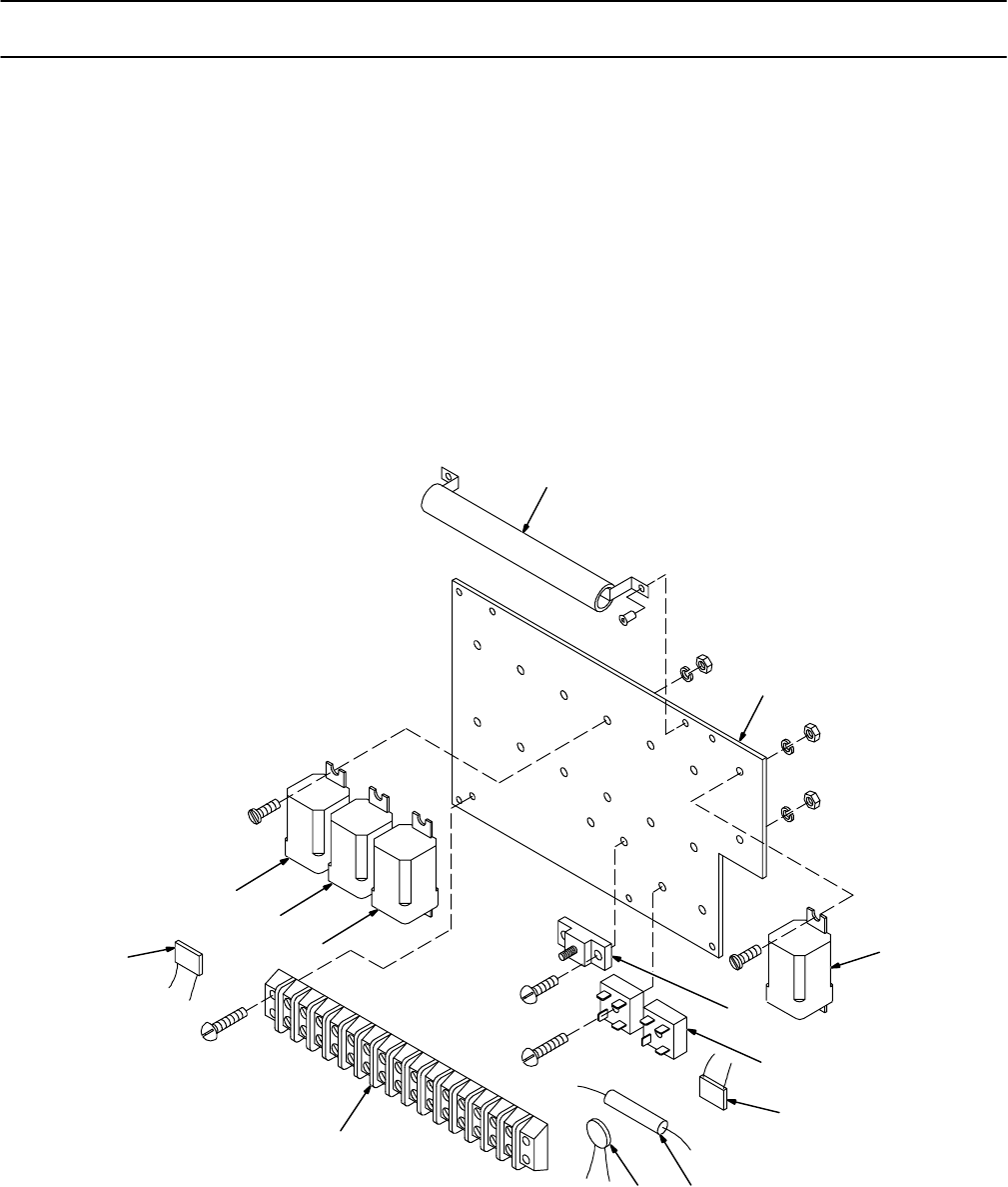
TM-353 Page 74 Syncrowave 250
Figure 10-5. Panel, Mtg Components (Fig 10-1 Item 7)
Description Quantity
Part
No.
Dia.
Mkgs.
Item
No.
1 R7 186 468 RESISTOR, WW fxd 100W 50 ohm 1. . . . . . . . . . . . . . . . . . . . . . . . . . . . . . . . . . . . . . . . . . . . . .
2 117 721 PANEL, mtg relay 1. . . . . . . . . . . . . . . . . . . . . . . . . . . . . . . . . . . . . . . . . . . . . . . . . . . . . . . . . . . . . . . . . .
3 CR2,6 110 386 RELAY, encl 24VAC DPDT 2. . . . . . . . . . . . . . . . . . . . . . . . . . . . . . . . . . . . . . . . . . . . . . . . . . .
4 2T 072 253 STUD, single connection 10-32 1. . . . . . . . . . . . . . . . . . . . . . . . . . . . . . . . . . . . . . . . . . . . . . . . . .
5 SR2,3 035 704 RECTIFIER, integ 40A 800V 2. . . . . . . . . . . . . . . . . . . . . . . . . . . . . . . . . . . . . . . . . . . . . . . . .
6 SN1,2 118 625 SNUBBER, poly metal film .5uf 200VDC 100 ohm 2. . . . . . . . . . . . . . . . . . . . . . . . . . . . . . .
7 R6 117 803 RESISTOR, WW fxd 10W 1K ohm 1. . . . . . . . . . . . . . . . . . . . . . . . . . . . . . . . . . . . . . . . . . . . . . . .
8 C20 119 834 CAPACITOR, cer disc .05uf 500V 1. . . . . . . . . . . . . . . . . . . . . . . . . . . . . . . . . . . . . . . . . . . . . . .
9 1T 117 372 BLOCK, term 10A 15P 1. . . . . . . . . . . . . . . . . . . . . . . . . . . . . . . . . . . . . . . . . . . . . . . . . . . . . . . . . .
108 023 LINK, jumper term blk 10A 3. . . . . . . . . . . . . . . . . . . . . . . . . . . . . . . . . . . . . . . . . . . . . . . . . . . . . . . . . . . . .
10 CR5 000 770 RELAY, encl 24VDC 3PDT 1. . . . . . . . . . . . . . . . . . . . . . . . . . . . . . . . . . . . . . . . . . . . . . . . . . .
11 CR1 052 964 RELAY, encl 24VDC DPDT 1. . . . . . . . . . . . . . . . . . . . . . . . . . . . . . . . . . . . . . . . . . . . . . . . . . .
ST-120 090-F
1
2
3
4
6
78
9
10
3
11
5
6
Figure 10-5. Panel, Mtg Components
BE SURE TO PROVIDE MODEL AND SERIAL NUMBER WHEN ORDERING REPLACEMENT PARTS.
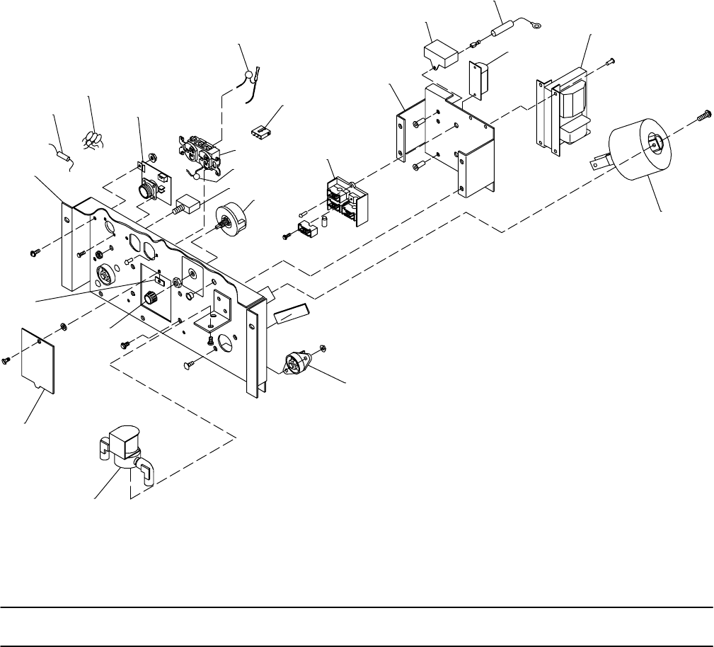
TM-353 Page 75Syncrowave 250
ST-120 003-P
1
2
3
4
5
6
7
8
910
11
13
14
15
16
17
18
19
20
21
22
23
Figure 10-6. Control Panel, Lower Front
Figure 10-6. Control Panel, Lower Front (Fig 10-2 Item 18)
Description Quantity
Part
No.
Dia.
Mkgs.
Item
No.
116 477 CONTROL PANEL, lower (Prior to JK572898) 1. . . . . . . . . . . . . . . . . . . . . . . . . . . . . . . . . . . . . . . . . . . . .
124 647 CONTROL PANEL, lower (Eff w/JK572898 thru JK682712) 1. . . . . . . . . . . . . . . . . . . . . . . . . . . . . . . .
131 217 CONTROL PANEL, lower (Eff w/JK682714 thru JK690986) 1. . . . . . . . . . . . . . . . . . . . . . . . . . . . . . . .
132 430 CONTROL PANEL, lower (Eff w/JK690987 thru KA806713) 1. . . . . . . . . . . . . . . . . . . . . . . . . . . . . . . .
137 516 CONTROL PANEL, lower (Eff w/KA806713 thru KA877024) 1. . . . . . . . . . . . . . . . . . . . . . . . . . . . . . .
147 793 CONTROL PANEL, lower (Eff w/KA877025 thru KF959378) 1. . . . . . . . . . . . . . . . . . . . . . . . . . . . . . . .
174 067 CONTROL PANEL, lower (Eff w/KF959379 thru KG170300) 1. . . . . . . . . . . . . . . . . . . . . . . . . . . . . . .
181 108 CONTROL PANEL, lower (Eff w/KG170301) 1. . . . . . . . . . . . . . . . . . . . . . . . . . . . . . . . . . . . . . . . . . . . .
1 114 742 PANEL, lower front (Prior to JK572898) 1. . . . . . . . . . . . . . . . . . . . . . . . . . . . . . . . . . . . . . . . . . . . . . .
1 124 784 PANEL, lower front (Eff w/JK572898 thru JK690986) 1. . . . . . . . . . . . . . . . . . . . . . . . . . . . . . . . . . .
1 130 582 PANEL, lower front (Eff w/JK690987 thru KB093120) 1. . . . . . . . . . . . . . . . . . . . . . . . . . . . . . . . . . .
1 147 795 PANEL, lower front (Eff w/KB093121 thru KF959176) 1. . . . . . . . . . . . . . . . . . . . . . . . . . . . . . . . . .
1 171 652 PANEL, lower front (Eff w/KF959177) 1. . . . . . . . . . . . . . . . . . . . . . . . . . . . . . . . . . . . . . . . . . . . . . . .
2 R25 137 429 RESISTOR, C 2W 3.3K ohm (Eff w/KA806713) 1. . . . . . . . . . . . . . . . . . . . . . . . . . . . . . . . .

TM-353 Page 76 Syncrowave 250
Figure 10-6. Control Panel, Lower Front (Continued)
Description Quantity
Part
No.
Dia.
Mkgs.
Item
No.
3 126 750 CAPACITOR ASSEMBLY, (Eff w/JK537589 thru JK690986) 1. . . . . . . . . . . . . . . . . . . . . . . . . . . . .
3 C14 098 566 CAPACITOR, (Prior to JK537589) 1. . . . . . . . . . . . . . . . . . . . . . . . . . . . . . . . . . . . . . . . . . . . .
3 C14 132 433 CAPACITOR, (Eff w/JK690987) 3. . . . . . . . . . . . . . . . . . . . . . . . . . . . . . . . . . . . . . . . . . . . . . .
121 270 RECEPTACLE/CAPACITOR,w/leads (Prior to JK682714). . . . . . . . . . . . . . . . . . . . . (consisting of) 1. . . . . . . . . . . . . . . . . . . . . . . . . . . . . . . . . . . . . . . . . . . . . . . . . . .
RC2 035 523 CONNECTOR, circ 5skt rcpt Amphenol MS-3102A-16S-8S 1. . . . . . . . . . . . . . . . . . . . . . . . . .
C16-19 119 856 CAPACITOR 2. . . . . . . . . . . . . . . . . . . . . . . . . . . . . . . . . . . . . . . . . . . . . . . . . . . . . . . . . . . . . . . . . .
PC2/RFC1 121 273 CIRCUIT CARD, snubber 1. . . . . . . . . . . . . . . . . . . . . . . . . . . . . . . . . . . . . . . . . . . . . . . . . .
039 273 CONNECTOR, circ 5 pin size 16S plug Amphenol MS-3106A-16S-8P. . . . . . . . . . . . . . . . . . . . .
039 685 CONNECTOR, circ clamp str rlf size 16 Amphenol 97-3057-8. . . . . . . . . . . . . . . . . . . . .
142 523 CONNECTOR/CAPACITOR, w/leads (Eff w/JK674521 thru . . . . . . . . . . . . . . . . . . . . . KF959378) (consisting of) 1. . . . . . . . . . . . . . . . . . . . . . . . . . . . . . . . . . . . . . . .
RC2 143 976 CONNECTOR w/SOCKETS 1. . . . . . . . . . . . . . . . . . . . . . . . . . . . . . . . . . . . . . . . . . . . . . . . . . . . .
C16 143 899 LEAD ASSY, elect 1. . . . . . . . . . . . . . . . . . . . . . . . . . . . . . . . . . . . . . . . . . . . . . . . . . . . . . . . . . . . . .
C17 143 897 LEAD ASSY, elect 1. . . . . . . . . . . . . . . . . . . . . . . . . . . . . . . . . . . . . . . . . . . . . . . . . . . . . . . . . . . . . .
C18 143 898 LEAD ASSY, elect 1. . . . . . . . . . . . . . . . . . . . . . . . . . . . . . . . . . . . . . . . . . . . . . . . . . . . . . . . . . . . . .
C19 143 900 LEAD ASSY, elect 1. . . . . . . . . . . . . . . . . . . . . . . . . . . . . . . . . . . . . . . . . . . . . . . . . . . . . . . . . . . . . .
RFC1/PC2 142 522 CHOKE 1. . . . . . . . . . . . . . . . . . . . . . . . . . . . . . . . . . . . . . . . . . . . . . . . . . . . . . . . . . . . . . . . .
4 PC2/RC1 157 959 CIRCUIT CARD ASSEMBLY, (Eff w/KF959379) (consisting of) 1. . . . . . . . . . . . . . . .
PLG21 153 501 CONNECTOR & SOCKETS 1. . . . . . . . . . . . . . . . . . . . . . . . . . . . . . . . . . . . . . . . . . . . . . . . . . .
134 734 CONNECTOR, circ 14 pin size 20 plug Amp 213571-2. . . . . . . . . . . . . . . . . . . . .
079 534 CONNECTOR, circ skt push-in 14-18ga Amp 66358-6. . . . . . . . . . . . . . . . . . . . .
079 739 CONNECTOR, circ clamp str rlf size 17-20 Amp 206322-2. . . . . . . . . . . . . . . . . . . . .
5 C6 164 290 CAPACITOR, polyp film 3.5uf 600VDC 1. . . . . . . . . . . . . . . . . . . . . . . . . . . . . . . . . . . . . . . . . . .
6 PLG3 131 204 CONNECTOR & SOCKETS 1. . . . . . . . . . . . . . . . . . . . . . . . . . . . . . . . . . . . . . . . . . . . . . . . . .
7 RC2 604 176 RECEPTACLE, straight duplex grd 2P3W 15A 125V 1. . . . . . . . . . . . . . . . . . . . . . . . . . . . .
073 690 CAP, straight P & S 2P3W 5266 DF. . . . . . . . . . . . . . . . . . . . .
8 C15 170 920 CAPACITOR 1. . . . . . . . . . . . . . . . . . . . . . . . . . . . . . . . . . . . . . . . . . . . . . . . . . . . . . . . . . . . . . . .
9 CB1 093 995 CIRCUIT BREAKER, man reset 1P 15A 250V 1. . . . . . . . . . . . . . . . . . . . . . . . . . . . . . . . . . .
10 R13 605 828 RHEOSTAT, WW 50W 1.5 ohm (Prior to KG170301) 1. . . . . . . . . . . . . . . . . . . . . . . . . . . . .
10 R13 174 037 RHEOSTAT, WW 50W 1.5 ohm (Eff w/KG170301 thru LA292998) 1. . . . . . . . . . . . . . . . .
10 R13 198 547 RHEOSTAT, WW 25W 1.5 ohm (Eff w/LA292999) 1. . . . . . . . . . . . . . . . . . . . . . . . . . . . . . .
010 493 BUSHING, snap-in nyl .625 ID x .875 mtg hole 1. . . . . . . . . . . . . . . . . . . . . . . . . . . . . . . . . . . . . . . . . . .
11 G ♦♦020 623 SPARK GAP ASSEMBLY (Prior to LA337284) 1. . . . . . . . . . . . . . . . . . . . . . . . . . . . . . . . . .
♦♦095 621 BASE, spark gap (Prior to LA337284) 1. . . . . . . . . . . . . . . . . . . . . . . . . . . . . . . . . . . . . . . . . . . . . . . .
♦♦020 622 HOLDER, points (Prior to LA337284) 4. . . . . . . . . . . . . . . . . . . . . . . . . . . . . . . . . . . . . . . . . . . . . . . . .
♦♦*020 603 POINT, spark gap (Prior to LA337284) 4. . . . . . . . . . . . . . . . . . . . . . . . . . . . . . . . . . . . . . . . . . . . . . .
11 G ♦♦203 419 SPARK GAP ASSEMBLY SERVICE KIT (for units prior to LA337284)) 1. . . . . . . . . . . . .
11 G ♦♦199 854 SPARK GAP ASSEMBLY (Eff w/LA337284) 1. . . . . . . . . . . . . . . . . . . . . . . . . . . . . . . . . . . .
♦♦199 855 BASE, spark gap (Eff w/LA337284) 1. . . . . . . . . . . . . . . . . . . . . . . . . . . . . . . . . . . . . . . . . . . . . . . . . .
♦♦199 856 HOLDER, points (Eff w/LA337284) 4. . . . . . . . . . . . . . . . . . . . . . . . . . . . . . . . . . . . . . . . . . . . . . . . . . .
♦♦*196 455 POINT, spark gap (Eff w/LA337284) 4. . . . . . . . . . . . . . . . . . . . . . . . . . . . . . . . . . . . . . . . . . . . . . . . .
088 731 BUSHING, snap-in nyl .375 ID x .500mtg hole 2. . . . . . . . . . . . . . . . . . . . . . . . . . . . . . . . . . . . . . . . . . . .
12 097 712 STRIP, insulator 1. . . . . . . . . . . . . . . . . . . . . . . . . . . . . . . . . . . . . . . . . . . . . . . . . . . . . . . . . . . . . . . . . . .
13 174 070 BRACKET, mtg components (Eff w/KG959379) 1. . . . . . . . . . . . . . . . . . . . . . . . . . . . . . . . . . . . . . . .
14 C3 106 935 CAPACITOR, polyp film 10uf 250VAC (Prior to KK001554) 1. . . . . . . . . . . . . . . . . . . . . . . . . .
14 C3 191 944 CAPACITOR, polyp film 10uf 250VAC (Eff w/KK001554) 1. . . . . . . . . . . . . . . . . . . . . . . . . . . .
15 R8 083 784 RESISTOR, WW fxd 100W 10 ohm (Prior to KG170301) 1. . . . . . . . . . . . . . . . . . . . . . . . . . .
15 R8 181 107 RESISTOR ASSEMBLY w/LEADS, (Eff w/KG170301) 1. . . . . . . . . . . . . . . . . . . . . . . . . . . . . .
16 C4 096 761 CAPACITOR, mica .002uf 10000V (CE Models Only) 1. . . . . . . . . . . . . . . . . . . . . . . . . . . . . .
16 C4 096 761 CAPACITOR, mica .002uf 10000V. . . . . . . . . . . . . . (Prior to KK001554 for nonCE Models) 1. . . . . . . . . . . . . . . . . . . . . . . . . . . . . . . . . . . . . . . . . . . . . . . . . . . . . . . . . . .
16 C4 201 197 CAPACITOR, polyp met film .002uf 10000VDC/4400VAC pnl mtg. . . . . . . . . . . . . . (Eff w/KK001554 for nonCE Models) 1. . . . . . . . . . . . . . . . . . . . . . . . . . . . . . . . . . . . . . . . . . . . . . . . . . . . . . . . . . . . .
000 681 STRIP, mtg HF coil (Prior to JK572898) 1. . . . . . . . . . . . . . . . . . . . . . . . . . . . . . . . . . . . . . . . . . . . . . . . .
124 649 STRIP, mtg HF coil (Eff w/JK572898) 1. . . . . . . . . . . . . . . . . . . . . . . . . . . . . . . . . . . . . . . . . . . . . . . . . . .
000 682 TUBING, fiber vulc .250 ID x .312 OD x .812 (Prior to JK572898) 2. . . . . . . . . . . . . . . . . . . . . . . . . . .
125 949 TUBING, fiber vulc .250 ID x .312 OD x 1.125 (Eff w/JK572898) 2. . . . . . . . . . . . . . . . . . . . . . . . . . . .
17 T2 074 398 TRANSFORMER, high voltage 115V pri 3600V sec 30mA 1. . . . . . . . . . . . . . . . . . . . . . . . . .

TM-353 Page 77Syncrowave 250
Figure 10-6. Control Panel, Lower Front (Fig 10-2 Item 18) (Continued)
Description Quantity
Part
No.
Dia.
Mkgs.
Item
No.
18 T3 115 967 COIL, HF coupling (Prior to JK572898) 1. . . . . . . . . . . . . . . . . . . . . . . . . . . . . . . . . . . . . . . . . . . .
18 T3 124 650 COIL, HF coupling (Eff w/JK572898 thru KF959378) 1. . . . . . . . . . . . . . . . . . . . . . . . . . . . . . .
18 T3 174 692 COIL, HF coupling (Eff w/KF959379) 1. . . . . . . . . . . . . . . . . . . . . . . . . . . . . . . . . . . . . . . . . . . . .
R9 030 603 RESISTOR, WW fxd 10W 10K ohm (Prior to KA877025) 1. . . . . . . . . . . . . . . . . . . . . . . . . . . . . .
19 Work. . . . . . .
Electrode 039 047 TERMINAL, power output (consisting of) 2. . . . . . . . . . . . . . . . . . . . . . . . . . . . . .
601 976 SCREW, stl hexhd .500-13 x 1.500 1. . . . . . . . . . . . . . . . . . . . . . . . . . . . . . . . . . . . . . . . . . . . . . . . . . . . .
039 049 TERMINAL BOARD, red 1. . . . . . . . . . . . . . . . . . . . . . . . . . . . . . . . . . . . . . . . . . . . . . . . . . . . . . . . . . . . . . .
601 880 NUT, stl hex jam .500 -13 1. . . . . . . . . . . . . . . . . . . . . . . . . . . . . . . . . . . . . . . . . . . . . . . . . . . . . . . . . . . . . .
039 044 BUS BAR, term bd 1. . . . . . . . . . . . . . . . . . . . . . . . . . . . . . . . . . . . . . . . . . . . . . . . . . . . . . . . . . . . . . . . . . . .
601 879 NUT, stl hex full fnsh .500-13 1. . . . . . . . . . . . . . . . . . . . . . . . . . . . . . . . . . . . . . . . . . . . . . . . . . . . . . . . . . .
20 GS1 174 036 VALVE, w/fittings & leads (consisting of) 1. . . . . . . . . . . . . . . . . . . . . . . . . . . . . . . . . . . . . . . .
010 296 FITTING, hose brs elbow M 1/4NPT x .625-18 2. . . . . . . . . . . . . . . . . . . . . . . . . . . . . . . . . . . . . . . . . . . .
035 601 VALVE, 115VAC 2 way 1/4 IPS port 1/8 orf 1. . . . . . . . . . . . . . . . . . . . . . . . . . . . . . . . . . . . . . . . . . . . . . .
PLG4 131 203 CONNECTOR & SOCKETS 1. . . . . . . . . . . . . . . . . . . . . . . . . . . . . . . . . . . . . . . . . . . . . . . . . . . . .
21 174 038 PANEL, door access HF (Eff w/KF959379) 1. . . . . . . . . . . . . . . . . . . . . . . . . . . . . . . . . . . . . . . . . . .
22 097 922 KNOB, pointer (Eff w/JK572898) 1. . . . . . . . . . . . . . . . . . . . . . . . . . . . . . . . . . . . . . . . . . . . . . . . . . . .
23 010 357 SPEED NUT 1. . . . . . . . . . . . . . . . . . . . . . . . . . . . . . . . . . . . . . . . . . . . . . . . . . . . . . . . . . . . . . . . . . . . .
24 605 742 CLIP, mtg resistor .500 ID core 2. . . . . . . . . . . . . . . . . . . . . . . . . . . . . . . . . . . . . . . . . . . . . . . . . . . . . .
*Recommended Spare Parts
♦♦Effective with Serial No.LA337284, Spark Gap Assembly 020 623 consisting of: Base 095 621, Holder 020 622,
and Points 020 603, is no longer available. If replacement parts are needed for any units with a Serial No. prior to
LA337284, you must first order and install Spark Gap Assembly Service Kit 203 419. To replace spark gap parts in
units with Serial No. LA337284 and following, or for units with Spark Gap Assembly Service Kit 203 419 installed, order
appropriate spark gap parts listed above as, eff/w Serial No. LA337284.
BE SURE TO PROVIDE MODEL AND SERIAL NUMBER WHEN ORDERING REPLACEMENT PARTS.

TM-353 Page 78 Syncrowave 250
Eff w/KE558763 the Water Valve Option (042 138) is no longer available
and all other options are available as Field Options only.
Description Quantity
Part
No.
Dia.
Mkgs.
Optional Equipment
042 138 WATER VALVE, (consisting of) 1. . . . . . . . . . . . . . . . . . . . . . . . . . . . . . . . . . . . . . . . . . . . . . . . . . . . . . . . .
WSI 035 601 VALVE, 115VAC 2 way 1/4 IPS port 1/8 orf 1. . . . . . . . . . . . . . . . . . . . . . . . . . . . . . . . . . . . . . . . . .
010 295 FITTING, pipe brs elbow M 1/4NPT x .625-18 2. . . . . . . . . . . . . . . . . . . . . . . . . . . . . . . . . . . . . . . . . . . .
116 201 BRACKET, mtg valve 1. . . . . . . . . . . . . . . . . . . . . . . . . . . . . . . . . . . . . . . . . . . . . . . . . . . . . . . . . . . . . . . . .
042 140 METER KIT, (consisting of) 1. . . . . . . . . . . . . . . . . . . . . . . . . . . . . . . . . . . . . . . . . . . . . . . . . . . . . . . . . . . .
A 115 920 METER, amp AC/DC 100MV 0-300 scale 1. . . . . . . . . . . . . . . . . . . . . . . . . . . . . . . . . . . . . . . . . . . . .
V 004 189 METER, volt AC/DC 0-100 scale 1. . . . . . . . . . . . . . . . . . . . . . . . . . . . . . . . . . . . . . . . . . . . . . . . . . . .
131 054 CONNECTOR & SOCKETS, (consisting of) 1. . . . . . . . . . . . . . . . . . . . . . . . . . . . . . . . . . . . . . . . . . . . . .
113 746 CONNECTOR, rect skt 24-18ga Molex 39-00-0038 8. . . . . . . . . . . . . . . . . . . . . . . . . . . . . . . . . . . . . . . .
042 142 SPOT TIMER, (consisting of) 1. . . . . . . . . . . . . . . . . . . . . . . . . . . . . . . . . . . . . . . . . . . . . . . . . . . . . . . . . .
CR3 006 393 RELAY, encl 24VAC DPDT 1. . . . . . . . . . . . . . . . . . . . . . . . . . . . . . . . . . . . . . . . . . . . . . . . . . . . . . .
RFC,VR1/PC3 120 875 CIRCUIT CARD, snubber 1. . . . . . . . . . . . . . . . . . . . . . . . . . . . . . . . . . . . . . . . . . . . . . . .
R10 030 108 POTENTIOMETER, C sltd sft 1/T 2W 100K ohm 1. . . . . . . . . . . . . . . . . . . . . . . . . . . . . . . . . . . .
S8 011 611 SWITCH, tgl DPDT 15A 125V 1. . . . . . . . . . . . . . . . . . . . . . . . . . . . . . . . . . . . . . . . . . . . . . . . . . . . . . .
TD2 047 133 RELAY, delay adj 120VAC DPDT 1. . . . . . . . . . . . . . . . . . . . . . . . . . . . . . . . . . . . . . . . . . . . . . . . . .
097 922 KNOB, pointer 1. . . . . . . . . . . . . . . . . . . . . . . . . . . . . . . . . . . . . . . . . . . . . . . . . . . . . . . . . . . . . . . . . . . . . . .
042 144 PRE-FLOW TIMER, (consisting of) 1. . . . . . . . . . . . . . . . . . . . . . . . . . . . . . . . . . . . . . . . . . . . . . . . . . . . .
CR4 006 393 RELAY, encl 24VAC DPDT 1. . . . . . . . . . . . . . . . . . . . . . . . . . . . . . . . . . . . . . . . . . . . . . . . . . . . . . .
R12,S9 115 862 POTENTIOMETER, C sltd sft 1/T .50W 500K ohm 1. . . . . . . . . . . . . . . . . . . . . . . . . . . . . . . .
TD3 116 476 TIMER, delay on make - preflow (consisting of) 1. . . . . . . . . . . . . . . . . . . . . . . . . . . . . . . . . . . . . .
115 856 CIRCUIT CARD, preflow (consisting of) 1. . . . . . . . . . . . . . . . . . . . . . . . . . . . . . . . . . . . . . . . . . . . . . . . . .
A50 008 971 IC, linear 741 1. . . . . . . . . . . . . . . . . . . . . . . . . . . . . . . . . . . . . . . . . . . . . . . . . . . . . . . . . . . . . . . . . . . .
C50 039 482 CAPACITOR, elctlt 100uf 35VDC 1. . . . . . . . . . . . . . . . . . . . . . . . . . . . . . . . . . . . . . . . . . . . . . . . . .
C51 091 378 CAPACITOR, tantlm 33uf 35VDC 1. . . . . . . . . . . . . . . . . . . . . . . . . . . . . . . . . . . . . . . . . . . . . . . . . .
C52 039 481 CAPACITOR, elctlt 3.3uf 50VDC 1. . . . . . . . . . . . . . . . . . . . . . . . . . . . . . . . . . . . . . . . . . . . . . . . . . .
C53 031 677 CAPACITOR, elctlt 5.6uf 35VDC 1. . . . . . . . . . . . . . . . . . . . . . . . . . . . . . . . . . . . . . . . . . . . . . . . . . .
C54 166 199 CAPACITOR, cer disc .05uf 500VDC 1. . . . . . . . . . . . . . . . . . . . . . . . . . . . . . . . . . . . . . . . . . . . . . .
CR50 039 486 RELAY, encl 24VDC SPDT 2.5A 1. . . . . . . . . . . . . . . . . . . . . . . . . . . . . . . . . . . . . . . . . . . . . . . . .
D50,51 026 202 DIODE, rect 1A 400V SP 2. . . . . . . . . . . . . . . . . . . . . . . . . . . . . . . . . . . . . . . . . . . . . . . . . . . . . .
Q50 000 088 TRANSISTOR, NPN 800mA 400V 1. . . . . . . . . . . . . . . . . . . . . . . . . . . . . . . . . . . . . . . . . . . . . . . . .
R50 074 121 RESISTOR, C 2W 3.3K ohm 1. . . . . . . . . . . . . . . . . . . . . . . . . . . . . . . . . . . . . . . . . . . . . . . . . . . . . .
R52 108 432 RESISTOR, MF .25W 2.21K ohm 1. . . . . . . . . . . . . . . . . . . . . . . . . . . . . . . . . . . . . . . . . . . . . . . . . .
R53 000 342 POTENTIOMETER, cermet trmr 1/T .5W 5K ohm 1. . . . . . . . . . . . . . . . . . . . . . . . . . . . . . . . . . . .
R54 093 030 RESISTOR, MF .25W 15K ohm 1. . . . . . . . . . . . . . . . . . . . . . . . . . . . . . . . . . . . . . . . . . . . . . . . . . . .
R55 028 273 RESISTOR, C .5W 2.7K ohm 1. . . . . . . . . . . . . . . . . . . . . . . . . . . . . . . . . . . . . . . . . . . . . . . . . . . . . .
R56 093 037 RESISTOR, MF .25W 47.5K ohm 1. . . . . . . . . . . . . . . . . . . . . . . . . . . . . . . . . . . . . . . . . . . . . . . . . .
R57 605 919 RESISTOR, C .25W 47 ohm 1. . . . . . . . . . . . . . . . . . . . . . . . . . . . . . . . . . . . . . . . . . . . . . . . . . . . . .
039 449 BRACKET, mtg circuit card 1. . . . . . . . . . . . . . . . . . . . . . . . . . . . . . . . . . . . . . . . . . . . . . . . . . . . . . . . . . . . .
097 922 KNOB, pointer 1. . . . . . . . . . . . . . . . . . . . . . . . . . . . . . . . . . . . . . . . . . . . . . . . . . . . . . . . . . . . . . . . . . . . . . .
042 353 POWER FACTOR CORRECTION, (consisting of) 1. . . . . . . . . . . . . . . . . . . . . . . . . . . . . . . . . . . . . . . .
C1 125 781 CAPACITOR, polyp film 150uf 250VAC 4. . . . . . . . . . . . . . . . . . . . . . . . . . . . . . . . . . . . . . . . . . . . . .
129 201 BRACKET, mtg capacitor 2. . . . . . . . . . . . . . . . . . . . . . . . . . . . . . . . . . . . . . . . . . . . . . . . . . . . . . . . . . . . . .


PRINTED IN USA 1998 Miller Electric Mfg. Co.
Miller Electric Mfg. Co.
An Illinois Tool Works Company
1635 West Spencer Street
Appleton, WI 54914 USA
International Headquarters–USA
Phone: 920-735-4505
USA & Canada FAX: 920-735-4134
International FAX: 920-735-4125
European Headquarters –
United Kingdom
Phone: 44 (0) 1204-593493
FAX: 44 (0) 1204-598066
Call
1-800-4-A-
MILLER
for your local
Miller distribu-
tor.
