Miltel Communications SPEEDTRD433L1 Low Power Meter Reading Transceiver User Manual Transceiver
Miltel Communications Ltd Low Power Meter Reading Transceiver Transceiver
Transceiver User Manual

Speed TxRx
Miltel Communications Ltd. 1
Speed TxRx
Tranceiver
FCC ID - SPEEDTRD433L1
User Manual
Miltel Communications Ltd. June 1998

Speed TxRx User Manual
Miltel Communications Ltd. 2
Table of Contents
Chapter 1 Introduction...................................................................................................3
1.1 Purpose and Use............................................................................................3
1.2 System General Description ...........................................................................3
Chapter 2 Theory of Operation .....................................................................................5
2.1 General Description ........................................................................................5
2.2 Block Diagram Description..............................................................................5
Chapter 3 Technical Characteristics............................................................................9
3.1 Technical Specification ...................................................................................9
3.1.1 Electrical .........................................................................................................9
3.1.2 Physical.........................................................................................................10
3.2 Label Contents..............................................................................................11
Chapter 4 Installation Instructions .............................................................................13
4.1 General.........................................................................................................13
4.2 Installation.....................................................................................................10

Speed TxRx User Manual
Miltel Communications Ltd. 3
Chapter 1
Introduction
1.1 Purpose and Use
The Speed TxRx Transceiver (FCC ID - SPEEDTRD433L1) is a low-power data link
transceiver that relays digital data from low power Transmitters (FCC ID -
MLLTX433L1), which are connected to water meters, to a Regional Concentrator. It
is also used in the receive mode as a front-end to the Concentrator. The information
in this manual is provided only as instructions for installation and does not entitle user
to make any modifications or adjustments.
1.2 System General Description
The Speed TxRx system is a computerized fully automatic radio device. It requires
no human intervention after initial installation. The device includes the following
parts:
1. Transmitter
2. Receiver
3. Controller
4. Antennas and cables
5. DC regulator
6. Enclosure
The Transceiver receives DC power and digital data from the Repeater or
Concentrator and Transmit \ Receive RF through coaxial cables which are connected
to half wavelength Dipole antennas.
Note: 1) The system, including transmitters, transceivers and concentrators, is
installed and maintained only by qualified professional technicians.
2) The device is not adjustable by user and is supplied by manufacturer
ready for installation witout provisions for adjustmant.

Speed TxRx
Miltel Communications Ltd. 5
Chapter 2
Theory of Operation
2.1 General Description
In receive mode, the Speed TxRx receives data from the Speed Tx Transmitters which
are deployed near the water meter/s or from other Speed TxRx units which are in
Transmit mode. The received data is processed differently whether the unit is
connected to a Repeater control device or as a front-end to a Concentrator. When
connected to a Repeater, the received data is processed in the Repeater’s controller.
Only messages, which need to be relayed, are transferred to the Transceiver’s
controller.
The Controller initiates a transmission only if 30 sec. have elapsed from the previous
transmission. Upon validation, the Controller switches the Transceiver to Transmit
mode and transmits the data. The controller also selects the antenna from which the
message will be transmitted/received.
When connected as a Concentrator front-end, the Transceiver operates in receive
mode. The received data is transferred to the concentrator for further processing of the
meter data.

Speed TxRx User Manual
Miltel Communications Ltd. 6
2.2 Block Diagram Description
2.2.1 General
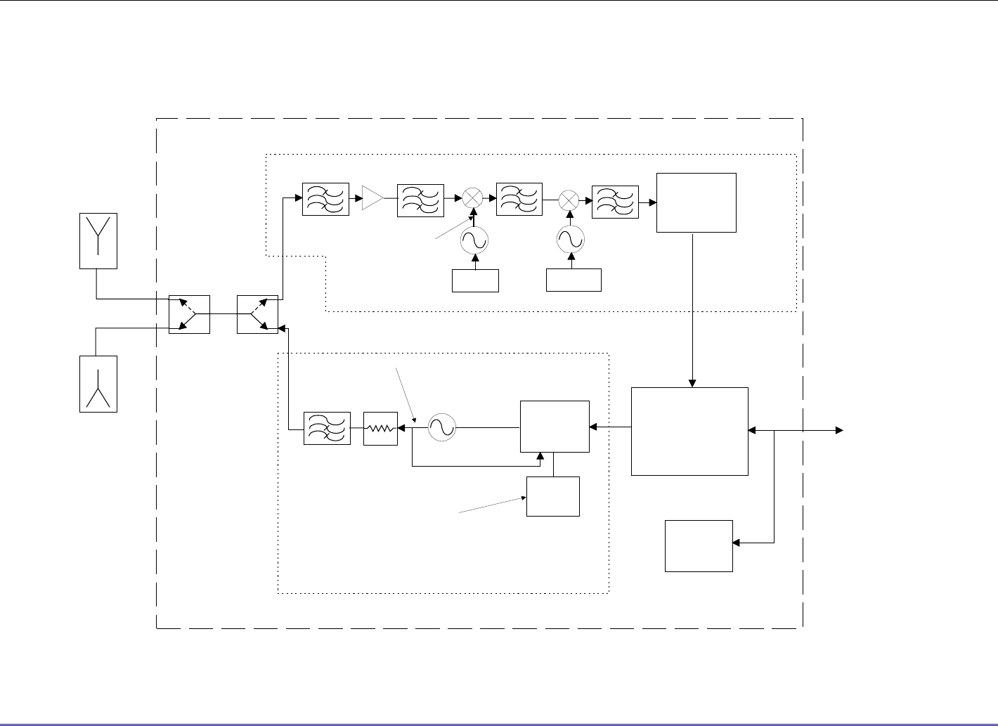
Figure 2-1 describes the block diagram of the Speed Tx Rx unit. RF is received or transmitted
from either antennas upon the controller selection. Two antennas are used to improve
performance in urban environment where shadowing, due to tall buildings, generates sever
multipath effect. This effect can reduce the received signal by more than 30dB, thus by switching
antennas periodically the transceiver improves reception.
2.2.2 Transmitter
A PLL IC ( MC13176 from Motorola Semiconductors) gets the reference, 13.56MHz, from a
crystal oscillator and locks the VCO output, divided by 32, to the crystal frequency. Therefore,
the output frequency equals Crystal_frequency x 32 = 433.92 MHz.
The message digital data from the Controller is shaped and modulates the VCO frequency. The
VCO output is attenuated by a resistive Π Attenuator. A 6 pole low pass filter that rejects the
harmonics, further filters the output. The output is routed through a T/R switch and a diversity
switch to the output/input UHF connectors.
Coaxial cables connect the half-wavelength dipole antennas with the Transceiver. All the
emissions parameters are in compliance with FCC part15C specifically the limitations set by
15.231(e). When the Transceiver is in the receive mode the voltages to the Transmitter are off.
Speed TxRx User Manual
Miltel Communications Ltd. 7
Figure 2-2: Speed TxRx Block Diagram
Antenna
Antenna
VCO
Phase Locked
LOOP(PLL)
MC13176
Crystal
13.56MHz
Internal
adjustment range
433.92MHz +/-
35KHz
433.92MHz
VCO
Crystal
13.56MHz
Diversity
switch T/R
switch
SAW filter
433.92MHz BPF
& LNA 10.7MHZ 1
st
IF
VCO
Crystal
10.245MHz
423.22MHz LO
455KHz 2
nd IF
FM Demodulator
Coaxial Cables
Harmonic Filter
& Attenuator
Dipole
Dipole
Transmitter
Transceiver Enclosure
Receiver
Controller
DC
Regulator
To Repeater
or Concentrator

Speed TxRx
Miltel Communications Ltd. 8
2.2.3 Receiver
The input signal from either ports is routed with the T/R switch to the receiver section. The signal
is filtered, amplified and further filtered by a high selectivity SAW filter. Local Oscillator
leakage is greatly reduced by the reverse isolation of the amplifier and mostly by the Narrow band
SAW filter.
The Receiver is a double down converter super_het receiver. The 2nd IF output is applied to an
FM discriminator that demodulates the signal and reproduces the digital data which is transferred
to the Repeater. A shielded 5-wire cable connects the Transceiver to a Repeater or a Concentrator.
2.2.4 Controller
The controller receives and sends data to and from the Repeater or the Concentrator. When a data
should be transmitted, The Controller turn on the voltages to the Transmit section and modulates
the transmitter VCO. The Controller is a single chip with integral RAM and ROM.
2.2.5 Regulator
The DC regulator filters The DC voltage from the Repeater or the Concentrator and distributes
the power accordingly.

Speed TxRx User Manual
Miltel Communications Ltd. 9
Chapter 3
Technical Characteristics
3.1 Technical Specification
3.1.1 Electrical
Transmitter
Max. Effective Radiated
Power (ERP) including
Dipole antennas
1.4µW peak (Complies with FCC
15.231(e))
Output frequency 433.92 MHz. Crystal Controlled.
Carrier wave modulation 2 levels FSK with a subcarier
Bandwidth 50KHz max. At –20dBc points
Transmit Duration 0.8 Sec Max.
Duration between
Transmissions
30 Seconds Min.
Receiver
Type Crystal Controlled, Super-Heterodyne
Frequency Conversions Two, 1st IF: 10.7MHz, 2nd IF: 455KHz
FM Demodulator Quadrature detector with a video filter
and a Compartor.
Sensitivity -117dBm at transceiver ports.
Measured with 10 messages with no
errors,

Speed TxRx User Manual
Miltel Communications Ltd. 10
General
Interface to
Repeater/Concentrator
Shielded 5-wire cable
Antennas Half wavelength Dipoles, 50ς better
than 2:1 VSWR
Power Supply 110V AC / 12V DC UL Certified
Converter
3.1.2 Physical
Operating temperature -10÷+60°C
Water Resistance Splash resistance (IP-64)
Length 160 mm.
Width 120 mm.
Depth 75 mm.
Weight (excluding
Antennas)
420 gr.
Enclosure An inner shielded steel box in a plastic
box housing. UHF connectors for RF
and a 5-wire shielded cable for Data
and DC.
Speed TxRx User Manual
Miltel Communications Ltd. 11
3.2 Label Contents
FCC ID: MLLSPEEDTRD433L1
Model: Speed TxRx_433_L1
S/N: YY-nnnnnn
Miltel Communications Ltd. Made in Israel
This device complies with Part 15 of the FCC rules. Operation is subjected to the
following two conditions: (1) This device may not cause harmful interference, and
(2) this device must accept any interference that may cause undesired operation.
Figure 3-1: Label

Chapter 4
Installation Instructions
4.1 General
The Speed TxRx Transceiver should be installed only by a professional technician.
Once installed, the Antennas and Coax Cables should not be modified as this may
effect performance and will violate the FCC requirements. The Speed TxRx unit
should be installed in a secure location so that it is not accessible.
4.2 Installation
Before installing the Speed TxRx Transceiver complete the antenna installation. The
antennas should be installed by a qualified installer according to the appropriate
guidelines and regulations. Antennas should be installed vertically. Distance between
antennas should be 40 cm. (min). After antenna installation coax cables should be
connected and secured. Once antennas are installed and coax cables are put in place
the Speed TxRx device can be installed as follows:
1) Loosen the four screws fastening the unit's box and open the box cover.
2) Install the box base at a secure location as close as possible to Antenna location.
3) Connect the Speed TxRx Transceiver to the Repeater or to the Concentrator
using approved 5 wire shielded cable.
4) Connect the Speed TxRx Transceiver to external Power Supply.
5) Connect both coax cables to Speed TxRx Transceiver and secure them in
place.
6) Close the unit's box cover.
7) Perform functional radio test and verify correct reception of data at
concentrator.