Miltel Communications SPEEDTX433L1 Low Power Meter Reading Transmitter User Manual Transmitter
Miltel Communications Ltd Low Power Meter Reading Transmitter Transmitter
Transmitter User Manual

Speed Tx User Manual
Miltel Communications Ltd. 1
Speed Tx
Low Power Wireless Data Link
FCC ID: SPEEDTx433L1
User Manual
Miltel Communications Ltd. June 1998

Speed Tx User Manual
Miltel Communications Ltd. 2
Table of Contents
Chapter 1 Introduction...................................................................................................3
1.1 Purpose and Use............................................................................................3
1.2 System General Description ...........................................................................3
Chapter 2 Theory of Operation .....................................................................................4
2.1 General Description ........................................................................................4
2.2 Block Diagram Description..............................................................................6
2.2.1 General...........................................................................................................6
2.2.1 Digital Section.................................................................................................7
2.2.3 RF Section ......................................................................................................8
Chapter 3 Technical Characteristics............................................................................9
3.1 Technical Specification ...................................................................................9
3.1.1 Electrical .........................................................................................................9
3.1.2 Physical...........................................................................................................9
3.2 Label Contents..............................................................................................10
Chapter 4 Installation Instructions .............................................................................11
4.1 General.........................................................................................................11
4.2 Installation.....................................................................................................11

Speed Tx User Manual
Miltel Communications Ltd. 3
Chapter 1
Introduction
1.1 Purpose and Use
The Speed Tx (FCC ID: SPEEDTx433L1) is a low-power data link transmitter that is
used for data acquisition in Miltel’s water consumption readings collection system.
This device is installed on-site by a professional field technician, thus it includes
technical terms. The equipment is not to be installed by a non-professional individual.
The information in this manual is provided only as instructions for installation and
does not entitle user to make any modifications or adjustments.
1.2 System General Description
The Speed Tx system is a computerized fully automatic radio device. It requires no
human intervention after initial installation. The system enables remote, continuous
and accurate reading of water consumption. The Speed Tx transmits the data
acquired from water meters to a regional concentrator (directly or via a repeater). The
concentrator transfers the data to the central computer for data collection and for
further analysis and reporting.
Note: 1) The system, including transmitters, transceivers and concentrators, is
installed and maintained only by qualified professional technicians.
2) The device is not adjustable by user and is supplied by manufacturer
ready for installation witout provisions for adjustmant.

Speed Tx User Manual
Miltel Communications Ltd. 4
Chapter 2
Theory of Operation
2.1 General Description
The Speed Tx is the first link in the water readings collection system. It is an
independent unit that does not require an external power source, wiring, or the
preparation of an infrastructure.
The unit is installed in proximity to the water meter/s and is connected to several
adjacent meters.
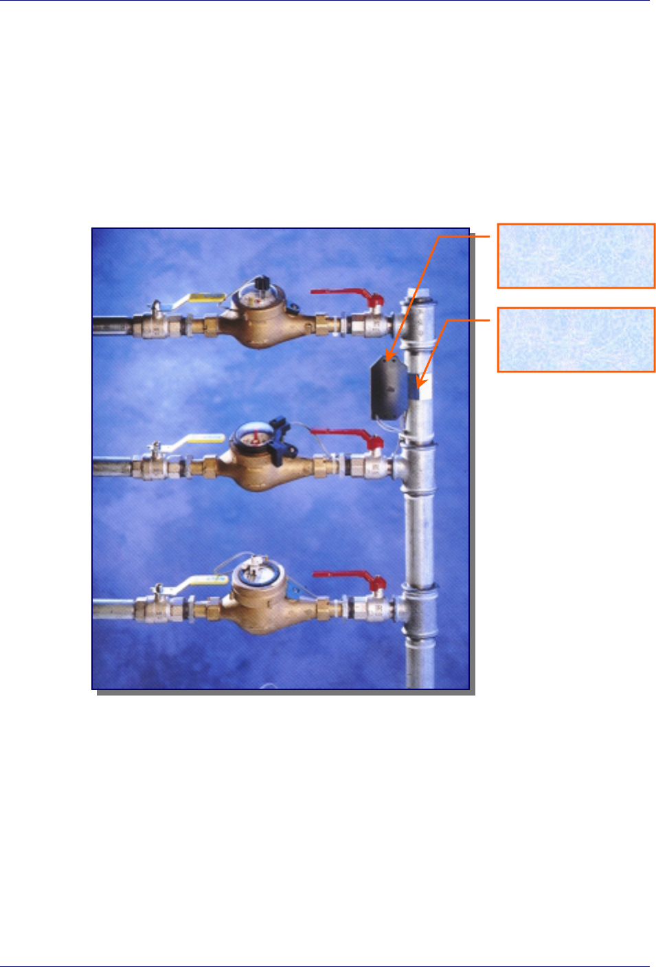
Figure 2-1 (see next page) shows a typical installation of a Speed Tx unit, connected
to several meters (of various types) at a single location. The unit can be connected to
any type of meter which has a pulsed output (a passive magnetic open/short reed
relay).
The Speed Tx acquires the consumption data from the water meters and stores this
data in its memory. The unit includes a miniature low-power RF transmitter which
transmits data on a periodic basis to a regional concentrator (directly or through a
relay station).
Speed Tx User Manual
Miltel Communications Ltd. 5
Figure 2-1: Speed Tx Typical Installation
Transmitter
(Speed Tx)
Clamp
Speed Tx User Manual
Miltel Communications Ltd. 6
2.2 Block Diagram Description
2.2.1 General
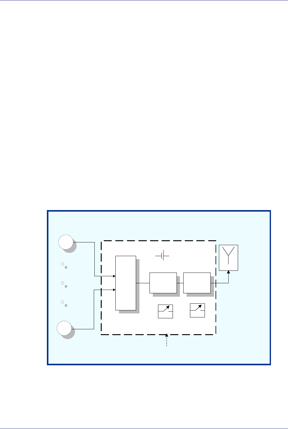
Figure 2-2 describes the block diagram of the Speed Tx unit. This device consists of
two major sections, all using a common power source:
Digital section (Micro Controller)
RF section
A 3.6 volts Lithium battery provides power to all parts of the device. The power
supply for the RF section is controlled via the Tx switch (not shown), thus cutting of
power to the transmitter unless necessary for actual data transmission (standby mode).
Figure 2-2: Speed Tx Block Diagram
Meter
1
Meter
n
Sensing
and
Support
Circuitry
Micro-
Controller
RF
Transmitter
Antenna
Battery
Device Enclosure
Magnetic
Switch Tamper
Switch

Speed Tx User Manual
Miltel Communications Ltd. 7
2.2.2 Digital Section
The digital section of the Speed Tx performs the following functions:
Samples reed switches to detect short/open from each meter.
Accumulates number of pulses for each meter separately
Stores data (including battery and tamper alarms) and stores information
internal memory
Interfaces the data to the RF section
The digital section is based on a central controller which accepts the following inputs:
a. Analog inputs (from reed-relay contacts) designated INPUT1 through INPUTn,
each indicating the advance of a single water meter. These are the only inputs
of the controller which are connected to the external source.
b. Magnetic switch input is utilized only for test.
c. The TAMPER SWITCH input is connected to a micro-switch that senses an
opening of the unit's box. This enables the Speed Tx to generate and transmit
an alarm signal in the event of unauthorized opening of the unit casing.
d. The LOW VOLTAGE input of the controller is connected to battery via a Low
Voltage Detector in order to sense and generate a low battery alarm.
Each of the external analog inputs to the controller advances a separate counter in
singular steps. The counters in the controller are not pre-settable or resettable to
avoid unauthorized tampering (counter matching is thus performed only by the central
computer, ensuring excellent data security at the sites).

Speed Tx User Manual
Miltel Communications Ltd. 8
The controller gathers the data for several hours before initiating a transmission. If
any of the counters has advanced by more than a preset value, or any alarm (tamper or
low voltage) has been received, the controller generates a single message
immediately. Any further message will include alarm information along with counter
data, if alarm condition still exists. Note: The duration interval between two
transmissions is always greater than 1 Hr.
a. The messages generated by the controller are 16 bytes each, and are outputed
from the digital section to the RF section as serial data (RS-232 standard
protocol) via the DATA OUT output of the controller.
b. The Tx control output of the controller is used for activating the TX switch for
the duration of the message, to enable power supply to the RF section thus
enabling the transmission of the message (transmit mode).
2.2.3 RF Section
The RF section consists of a phased-locked loop (PLL) and a low-power amplifier
connected to an integral antenna.
The PLL reference is driven by a 13.56 MHz. crystal oscillator. This reference is
phase-compared by the Phase Detector with the divided output frequency.
The phase detection signal from the detector is filtered by the PLL Loop Filter and
then summed with the shaped signal received from the digital section by the Sum
Network block. The output of the Sum Network is the control signal that modulates
and locks the Voltage Control Oscillator (VCO).

Speed Tx User Manual
Miltel Communications Ltd. 9
Chapter 3
Technical Characteristics
3.1 Technical Specification
3.1.1 Electrical
Max Effective Radiated Power (ERP) 1.4 µW Peak (Complies with FCC 15.231(e) )
Output frequency 433.92 MHz
Carrier wave modulation 2 Level FSK
Power supply Lithium battery, 3.6 Volt
Input Channels 1-8 Water Meters
Compatibility Any type of meter which has a reed relay switch
(pulsed output)
Transmission Duration 0.8 Sec. Max.
Duration between
Transmissions
1 Hr. Min.
3.1.2 Physical
Operating temperature -10÷+60°C
Water Resistance Splash resistance (IP-64)

Speed Tx User Manual
Miltel Communications Ltd. 10
Length 11 cm.
Width 8 cm.
Depth 3 cm.
Weight (excluding clamp) 200 gr.
Weight (including clamp) 500 gr.
Clamp material stainless steel
Clamp screws protected from dismantling
3.2 Label Contents (see file: Speed_Tx ID Label)
FCC ID: MLLSPEEDTx433L1
Model: Speed Tx_433_L1
S/N: YY-nnnnnn
Miltel Communications Ltd. Made in Israel
This device complies with Part 15 of the FCC rules. Operation is subjected to
the following two conditions: (1) This device may not cause harmful
interference, and (2) this device must accept any interference that may cause
undesired operation.
Figure 3-1: Label Design

Chapter 4
Installation Instructions
4.1 General
The Speed Tx is installed by a professional technician. Several possibilities for
installation have been programmed into the system in order to provide solutions for
installation of various types of water meters. The Speed Tx installation is performed
using a stainless steel clamp that enables connection to pipelines of different
diameters (0.75", 1.00", 1.50" or 2.00").
The Speed Tx unit is protected so that it is impossible to open or dismantle the box
without breaking the four one-time screw locks.
4.2 Installation
For on-site installation of the Speed Tx device, proceed as follows:
1) Loosen the four screws fastening the unit's box and open the box cover.
2) Install the unit's box base as required:
a. For pipeline installations (as in Figure 2-1), first attach the stainless steel
clamp (see Figure 4-1) to the pipeline, close it around the pipeline and
fasten the screw in the middle of the device. Place the unit's box base on
top of the screw and install it using two steel screws.

Speed Tx User Manual
Miltel Communications Ltd. 12
b. For wall mounting of the unit, install the base directly onto the wall or
surface using the two steel screws.
3) Connect the wire pairs from the water meters to the terminal blocks on the PCB.
Up to four such pairs can be connected, with unused connections left open (i.e.,
no termination is required).
Note
Connect each pair of wires to the respective terminals; note the
connections for future reference.
4) Close the unit's box cover.
5) Perform functional radio test by touching box corner with strong magnet
(trigger transmission). Verify correct reception of data at base station
(concentrator). Update water actual readings for the respective meter.
6) Close the four screws fastening the cover.
7) Insert plastic protection plugs.
Figure 4-1: Speed Tx - Pipeline Installation