Miltel Communications SPEEDTXP45-47 Meter Transmitter User Manual TxP UserManual
Miltel Communications Ltd Meter Transmitter TxP UserManual
Users Manual Revised
Miltel Transmitter
Wireless Transmitter
for Data Collection
FCC ID: MLLSPEEDTXP45-47
User Manual
Miltel Communications Ltd. February 2007

Table of Contents
Chapter 1 Introduction ..............................................................................................3
1.1 Purpose and Use........................................................................................3
1.2 System General Description.......................................................................3
Chapter 2 Theory of Operation ..................................................................................4
2.1 General Description....................................................................................4
2.2 Block Diagram Description .........................................................................6
Chapter 3 Technical Characteristics.........................................................................9
3.1 Technical Specification...............................................................................9
Chapter 4 Installation Instructions..........................................................................10
4.1 General.....................................................................................................10
4.2 Installation ................................................................................................10
Chapter 5 Regulatory Compliance ..........................................................................15
3.1 FCC Statement ........................................................................................15

Chapter 1
Introduction
1.1 Purpose and Use
The Miltel Transmitter (FCC ID: MLLSPEEDTXP45-47) is a data link transmitter that
is used for data acquisition in Miltel’s telemetric data collection system. This device
is installed on-site by a professional field technician, thus it includes technical terms.
The equipment is not to be installed by a non-professional individual that has not
been trained and authorized.
1.2 System General Description
The Miltel data collection system is a computerized fully system incorporating one-
way transmitters that automatically collect data from utility meters and/or other
sensors. The system requires no human intervention after initial installation. The
system enables remote, continuous and accurate reading of water or gas consumption.
The Miltel TxP transmits the data acquired from various sensors such as water
meters, electric meters, temperature or moisture sensors or any other analog or digital
sensor to a receiver connected to a regional data concentrator. The concentrator
transfers the data to the central computer for data collection and for further analysis
and reporting.

Chapter 2
Theory of Operation
2.1 General Description
The Miltel TxP is the first link in the data collection system. It is an independent unit
that does not require an external power source, wiring, or the preparation of any
special infrastructure. The unit is installed in proximity to the physical sensor and can
be connected to several different sensors in parallel (for example four water meters of
adjacent apartment, three ground moisture sensors at different depths, etc).
Pictures 2-1 shows a typical installations of a Miltel TxP unit. The unit can be
connected to any type of sensor which has a digital output, analog output, dry contact
pulsed output (a passive magnetic open/short reed relay), or any active pulse or
encoded output.
The Miltel Transmitter acquires the data from the sensor and stores this data in its
internal memory. The unit includes a miniature RF transmitter which transmits the
data on a periodic basis to a regional concentrator.
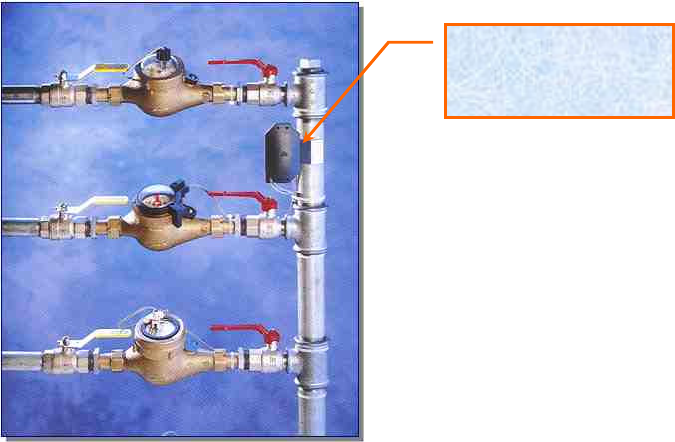
Figure 2-1: Miltel Transmitter Typical Multi Meter Installation
Miltel TxP
Transmitter
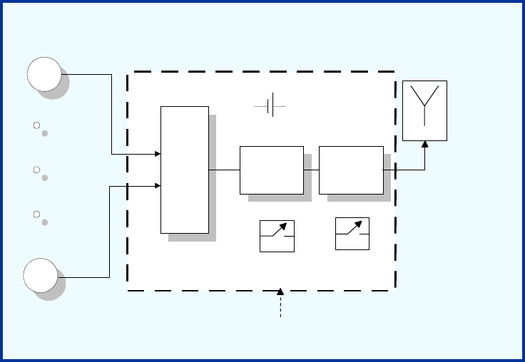
2.2 Block Diagram Description
2.2.1 General
Figure 2-2 describes the block diagram of the Miltel Transmitter unit. This device
consists of two major sections, all using a common power source:
Digital section (Micro Controller)
RF section
A 3.6 volts Lithium battery provides power to all parts of the device. The power
supply for the RF section is controlled via the Tx switch (not shown), thus cutting of
power to the transmitter unless necessary for actual data transmission (standby mode).
Figure 2-4: Miltel Transmitter Block Diagram
Sensor
1
Sensor
n
Sensing
an
d
Suppor
t
Circuitry
(Input Port)
Micro-
Controlle
r
RF
Transmitter
Antenna
Battery
Device Enclosure
Magnetic
Switch
Tamper
Switch
(opt.)
2.2.2 Description of Operation
The digital section of the Miltel Transmitter performs the following functions:
Samples analog sensors OR communicates with digital sensors
Accumulates data for each sensor separately
Stores data (including alarms) in internal memory
Interfaces the data to the RF section
The controller gathers the data for 1-240 minutes before initiating a transmission. If
any of the counters/sensors has exceeded a preset value, or any alarm (such as tamper)
has been received, the controller generates a single message immediately. Any
further message will include alarm information along with counter data, if alarm
condition still exists.
The messages generated by the controller are 16-48 bytes each (depending on the
number and type of sensors connected). The messages are exported from the digital
section to the RF section as serial data (RS-232 standard protocol) via the DATA OUT
output of the controller.
The Tx control output of the controller is used for activating the TX switch for the
duration of the message, to enable power supply to the RF section thus enabling the
transmission of the message (transmit mode).
The RF section takes the message and transmits it through the RD circuitry.

Chapter 3
Technical Characteristics
3.1 Technical Specification
3.1.1 Electrical
Max Effective Radiated Power (ERP) 116 mW
Output frequency 450-470 MHz
Carrier wave modulation 2 Level FSK
Power supply Lithium battery, 3.0-3.6 Volt
Input Channels Pulse / Analog / Digital
Duration between automatic transmissions At least 10 Min.
3.1.2 Physical
Operating temperature -30°C ÷+50°C
Water Resistance IP64 / IP68 (optimal)
Dimensions Enclosure Type B Enclosure Type N Enclosure Type S
Length 11 cm. 11 cm. 11 cm.
Width 8 cm. 8 cm. 8 cm.
Depth 3 cm. 3 cm. 3 cm.

Chapter 4
Installation Instructions
4.1 General
The Miltel Transmitter is installed by a professional technician. Several possibilities
for installation have been programmed into the system in order to provide solutions
for installation of various types of sensors including water, gas or electric meters.
4.2 Installation
For on-site installation of the Miltel TxP Transmitter device, proceed as follows:
1) Loosen the four screws fastening the unit's box and open the box cover.
2) Install the unit's box base as required:
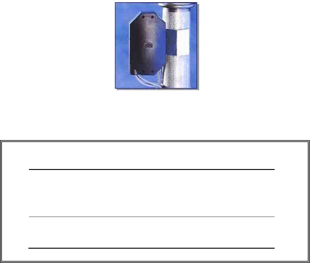
3) For pipeline installations (as in Figure 2-1), first attach the stainless steel clamp (see
Figure 4-1) to the pipeline, close it around the pipeline and fasten the screw in the
middle of the device. Place the unit's box base on top of the screw and install it using
two steel screws.
4) For wall mounting of the unit, install the base directly onto the wall or surface using
the two steel screws.
5) Connect the wire pairs from the water meters to the terminal blocks on the PCB. Up to
four such pairs can be connected, with unused connections left open (i.e., no
termination is required).
Note
Connect each pair of wires to the respective terminals; note the
connections for future reference.
6) Close the unit's box cover.
7) Perform a functional radio transmission test by touching the side of the transmitter
enclosure with a strong magnet (trigger transmission). Verify the correct reception
of the data at the base station (concentrator). Update water actual readings for the
respective meter.
8) Close the four screws fastening the cover.
9) Insert plastic protection plugs.
Figure 4-1: Miltel Transmitter - Pipeline Installation
N
NO
OT
TI
IC
CE
E
This equipment must be installed only by a professional and certified
installer that was trained in the proper installation of this device. The
intended use is only for the specific application the device was
designed for.
Changes or modifications not expressly approved by the manufacturer
could void the user's authority to operate this equipment.

Chapter 5
Regulatory Compliance
5.1 FCC Statement
The Speed TxP transmitter has been tested and found to comply with the limits for a Class B
digital device, pursuant to Part 15 of the FCC Rules. These limits are designed to provide
reasonable protection against harmful interference in a residential installation. This equipment
generates, uses and can radiate radio frequency energy and, if not installed and used in
accordance with the instructions, may cause harmful interference to radio communications.
However, there is no guarantee that interference will not occur in a particular installation. If this
equipment does cause harmful interference to radio or television reception, which can be
determined by turning the equipment off and on, the user is encouraged to try to correct the
interference by one or more of the following measures:
- Reorient or relocate the transmitter
- Increase the separation between the equipment and receiver.
- Connect the equipment into an outlet on a circuit different from that to which the receiver is
connected.
- Consult the dealer or an experienced radio/TV technician for help.
Declaration of Conformity
The Speed TxP product complies with Part 15 of the FCC Rules. Operation is subject
to the following two conditions: (1) this device may not cause harmful interference,
and (2) this device must accept any interference received, including interference that
may cause undesired operation.

Licensing Notice
The FCC rules require the equipment user to obtain a site license before operation of
this equipment. Licensing of the equipment is the user’s responsibility. The user is
required to contact an authorized FCC coordinator for the purpose of obtaining the
proper license for the specific location/site where the equipment is to be installed. We
strongly recommend that the user should obtain the proper frequency license before
ordering of the equipment.
NOTE: The antenna used for this product must be installed to
normally provide minimum separation distance of at least 20 cm
from all persons and must not be co-located or operating in
conjunction with any other antenna or transmitter.