Milwaukee Ravl42 Users Manual
RAVL42 to the manual bdc3e42d-286f-43ce-b0e0-4215b00b386e
2015-02-02
: Milwaukee Milwaukee-Ravl42-Users-Manual-437756 milwaukee-ravl42-users-manual-437756 milwaukee pdf
Open the PDF directly: View PDF ![]() .
.
Page Count: 42
INSTALLER: Leave this manual with the appliance.
CONSUMER: Retain this manual for future reference.
INSTALLATEUR: Laissez cette notice avec l'appareil.
CONSOMMATEUR: Conservez cette notice pour consul-
tation ultérieure.
- Do not store or use gasoline or other flammable vapors and
liquids in the vicinity of this or any other appliance.
- WHAT TO DO IF YOU SMELL GAS
• Do not try to light any appliance.
• Do not touch any electrical switch; do not use any
phone in your building.
• Immediately call your gas supplier from a neighbor’s
phone. Follow the gas supplier’s instructions.
• If you cannot reach your gas supplier, call the fire
department.
- Installation and service must be performed by a quali-
fied installer, service agency or the gas supplier.
WARNING: If the information in these instructions is
not followed exactly, a fire or explosion may result
causing property damage, personal injury or death.
- Ne pas entreposer ni utilizer d’essence ni d’autres
vapeurs ou liquides inflammables dans le voisinage
de cet appareil ou de tout autre appareil.
- QUE FAIRE SI VOUS SENTEZ UNE ODEUR DE GAZ:
• Ne pas tenter d’allumer d’appareil.
• Ne touchez à aucan interrupteur. Ne pas vous servir
des téléphones se trouvant dans le bâtiment où vous
trouvez.
• Appelez immédiatement votre fournisseur de gaz
depuis un voisin. Suivez les instructions du fournis-
seur.
• Si vous ne pouvez rejoindre le fournisseur de gaz,
appelez le service des incindies.
- L’installation et l’entretien doivent être assurés par un
installateur ou un service d’entretien qualifié ou par
le fournisseur de gaz.
AVERTISSEMENT: Assurez-vous de bien suivre les
instructions données dans cette notice pour réduire
au minimum le risque d’incindie ou d’explosion ou
pour éviter tout dommage matériel, toute blessure
ou la mort.
INSTALLATION AND OPERATION
Ce manuel d’installation est disponible en francais, simplement en faire la
demande. Numéro de la pièce 775,219CF.
MODEL
P/N 775,219M REV. D 03/2010
Direct-Vent
RAVELLE™ 42
This appliance may be installed in an aftermarket permanently located, manufactured home (USA only) or mobile
home, where not prohibited by local codes. This appliance is only for use with the type of gas indicated on the rating
plate. This appliance is not convertible for use with other gases, unless a certified kit is used.
WARNING
AVERTISSEMENT
UNE SURFACE VITRÉE CHAUDE PEUT
CAUSER DES BRÛLURES.
LAISSER REFROIDIR LA SURFACE
VITRÉE AVANT D'Y TOUCHER.
NE PERMETTEZ JAMAIS À UN ENFANT
DE TOUCHER LA SURFACE VITRÉE.
HOT GLASS WILL
CAUSE BURNS.
DO NOT TOUCH GLASS
UNTIL COOLED.
NEVER ALLOW CHILDREN TO
TOUCH GLASS.
TM
RAVL42
US
Portland
OTL Report No. 050-S-08c-5

2
CONGRATULATIONS!
When you purchased your new gas fireplace, you joined the
ranks of thousands of individuals whose answer to their home
heating needs reflects their concern for aesthetics, efficiency
and our environment. We extend our continued support to help
you achieve the maximum benefit and enjoyment available from
your new gas fireplace.
Thank you for selecting a Lennox Hearth Products gas fireplace
as the answer to your home heating needs.
TABLE OF CONTENTS
Using this Manual ...................................................... 2
Safety and Warning Information ....................................... 3
Orifice Size/Altitude Adjustment .......................................... 4
Smoke Detectors ............................................................ 4
Ravelle™ 42 Fireplace ..................................................... 4
Codes and Approvals ....................................................... 4
Commonwealth of Massachusetts Requirements ...................... 4
New York City, New York (MEA) .......................................... 4
Pre-Installation............................................................6-7
Features ............................................................ 6
Venting .............................................................. 6
Fuel.................................................................. 6
Specifications ...................................................... 6
Packaging List ..................................................... 6
Preparing your Fireplace for Installation ......................... 7
Clearances to Combustibles ..................................... 7
Installation ............................................................... 8-13
Framing Dimensions ............................................. 8
Fireplace Dimensions ............................................ 9
Raised Installations .............................................10
Hearth Extension Considerations .............................. 10
Facing Installation Considerations ............................ 11
Face Installation .................................................13
Vent Installation .......................................................14-28
Application ........................................................14
Vent Parts List ....................................................14
Vent Considerations .............................................16
Horizontal Vent Installation ..................................... 17
Vertical Vent Installation ........................................ 17
Flue Restrictors ..................................................18
Vertical Vent Termination Clearances ........................ 18
Horizontal Terminations ......................................... 19
Vertical Terminations ............................................ 19
Horizontal Vent Termination Clearances .....................20
Brick Panel and Log Set Installation ....................................21
Electrical Connections ....................................................22
Blower Removal ...........................................................22
Gas Line Installation ......................................................23
Gas Pressure Requirements .................................... 23
LP and Natural Gas Supplies ...................................23
Increasing Efficiency And Hot Air Movement ..........................24
Forced Air Heating Installation ......................................25-28
Attaching Safety In Operation Warnings ............................... 29
Operating Instructions ................................................30-33
Pre-Lighting Checklist ........................................... 30
Lighting Instructions ............................................. 30
Flame Color and Behavior ......................................31
Air Shutter Adjustment ..........................................32
Paint Curing ....................................................... 32
Quiet Operation ................................................... 32
Blower Operation ................................................. 32
Optional Wall Thermostat ....................................... 32
Operating Options ................................................ 33
Millivolt Control System ........................................ 33
Maintenance and Servicing ..........................................34-35
Maintenance Checklist ..........................................34
Vent Pipe Maintenance .......................................... 34
Opening and Removing Door ................................... 35
Glass/Door Maintenance ........................................ 35
Fuel Conversion .................................................. 35
Troubleshooting ............................................................36
Replacement Parts ........................................................37
Accessories ............................................................. 37-38
Fireplace Labels ....................................................... 39-40
Product Reference Information .......................................... 42
USING THIS MANUAL
Please read and carefully follow all of the instructions found in this
manual. Please pay special attention to the safety instructions provided
in this manual.
PRODUCT IS SUBJECT TO CHANGE WITHOUT NOTICE
3
IMPORTANT SAFETY AND WARNING
INFORMATION
WARNING
Young children should be carefully supervised when
they are in the same room as the appliance. Tod-
dlers, young children and others may be susceptible
to accidental contact burns. A physical barrier is
recommended if there are at risk individuals in the
house. To restrict access to a fireplace or stove,
install an adjustable safety gate to keep toddlers,
young children and other at risk individuals out of
the room and away from hot surfaces.
AVERTISSEMENT
Les jeunes enfants devraient être surveillés étroite-
ment lorsqu’ils se trouvent dans la même pièce que
l’appareil. Les tout petits, les jeunes enfants ou les
adultes peuvent subir des brûlures s’ils viennent en
contact avec la surface chaude. Il est recommandé
d’installer une barrière physique si des personnes à
risques habitent la maison. Pour empêcher l’accès
à un foyer ou à un poêle, installez une barrière de
sécurité; cette mesure empêchera les tout petits,
les jeunes enfants et toute autre personne à risque
d’avoir accès à la pièce et aux surfaces chaudes.
WARNING
Improper installation, adjustment, alteration, ser-
vice or maintenance can cause injury or property
damage. Refer to this manual. For assistance or
additional information consult a qualified installer,
service agency or the gas supplier.
WARNING
Failure to comply with these installation instructions
will result in an improperly installed and operating
appliance, voiding its warranty. Any change to this
appliance and/or its operating controls is danger-
ous.
WARNING
Clothing or other flammable material should not
be placed on or near the appliance.
AVERTISSEMENT
On ne devrait pas placer de vêtements ni d’autres
matières inflammables sur l’appareil ni à prox-
imité.
WARNING
Any safety screen or guard removed for servicing
the appliance must be replaced prior to operating
the appliance.
AVERTISSEMENT
Tout écran ou protecteur retiré pour permettre
l’entretien de l’appareil doit être remis en place
avant de mettre l’appareil en marche.
WARNING
Improper installation or use of this appliance can
cause serious injury or death from fire, burns,
explosion or carbon monoxide poisoning.
WARNING
Children and adults should be alerted to the hazards
of high surface temperature and should stay away to
avoid burns or clothing ignition.
AVERTISSEMENT
Les enfants et les adultes devraient être infor-més
des dangers que posent les températures de surface
élevées et se tenir à distance afin d’éviter des brûlures
ou que leurs vêtements ne s’enflamment.
WARNING
DO NOT ATTEMPT TO ALTER OR MODIFY THE CON-
STRUCTION OF THE APPLIANCE OR ITS COMPO-
NENTS. ANY MODIFICATION OR ALTERATION MAY
VOID THE WARRANTY, CERTIFICATION AND LISTINGS
OF THIS UNIT.

4
FOR YOUR SAFETY do not install or operate this appliance without
first reading and understanding this manual. Any installation or
operation of the appliance deviating from that which is stated
in this manual WILL void the warranty and may be hazardous.
INSTALLATION AND REPAIR SHOULD ONLY BE DONE BY
A QUALIFIED SERVICE TECHNICIAN. DO NOT ATTEMPT
TO SERVICE THE APPLIANCE YOURSELF.
Do not make any make-shift compromises during installation.
Any modification or alteration may result in damage to the ap-
pliance or dwelling and will void the warranty, certification and
listings of this unit.
Failure to use manufacturer provided parts, variations in tech-
niques and construction materials or practices other than those
described in this manual may create a fire hazard and void the
limited warranty.
This gas appliance must be equipped for the proper fuel type
and altitude at which it will be operated. Any operation outside
the parameters outlined in this manual may result in a hazard-
ous condition and will void the warranty. Please carefully read
the sections pertaining to these subjects and/or be sure your
appliance is properly equipped.
Never use solid fuels such as wood, paper, cardboard, coal, or
any flammable liquids, etc., in this appliance.
Any grill, panel, or glass removed for service MUST be replaced
prior to operating the appliance. Do not operate appliance with
the glass front removed, cracked or broken.
Gold and nickel plated surfaces must be cleaned with glass
cleaner and a clean soft cloth before firing the first time or
fingerprints will remain permanently. NEVER use brass polish
to clean gold or nickel, this will remove the plating!!!
When opening the lower door on the face while the appliance is
burning, pull at the far left or far right vent openings, because
the door is hot during operation.
LHP, its employees, or any of its representatives assume no
responsibility for any damages caused by an inoperable, inad-
equate, or unsafe condition as a result of any improper operation,
service or installation procedures, whether direct or indirect.
Due to high temperatures, the appliance should be located out
of traffic and away from furniture and draperies.
En raison des températures élevées, l’appareil devrait être
installé dans un endroit où il y a peu de circulation et loin du
mobilier et des tentures.
Provide adequate clearances around air openings and adequate
accessibility clearance for service and proper operation. Never
obstruct the front openings of the appliance.
These appliances are designed to operate on natural or propane
gas only. The use of other fuels or combination of fuels will de-
grade the performance of this system and may be dangerous.
These appliances are designed as supplemental heaters. There-
fore, it is advisable to have an alternate primary heat source
when installed in a dwelling.
These appliances must not be connected to a chimney or flue
serving a separate solid fuel burning appliance.
These appliances are vented gas appliances. Do not burn wood
or other material in these appliances.
This appliance is only for use with the type of gas indicated on
rating plate. This appliance is not convertible for use with other
gases, unless a certified kit is used.
Cet appareil doit être utilisé uniquement avec les types de gaz
indiqués sur la plaque signalétique. Ne pas l'utiliser avec
d'autres gaz sauf si un kit de conversion certifié est installé.
Hot while in operation. Do not touch. Severe Burns may result.
Keep children, clothing furniture, gasoline and other liquids
having flammable vapors away.
L’appareil est chaud lorsqu’il fonctionne. Ne pas toucher
l’appareil. Risque de brûlures graves. Surveiller les enfants.
Garder les vêtements, les meubles, l’essence ou autres liquides
produisant des vapeur inflammables loin de l’appareil.
This appliance may be installed in an aftermarket, permanently
located, manufactured home (USA only) or mobile home, where
not prohibited by local codes.
Cet appareil peut être installé dans une maison préfabriquée
(mobile) déjà installée à demeure si les règlements locaux le
permettent.
Ensure clearances are in accordance with local installation
codes and the requirements of the gas supplier.
Dégagement conforme aux codes d'installation locaux et aux
exigences du foumisseunde gaz.
Installation and repair should be done by a qualified service
person. The appliance should be inspected before use and at
least annually by a professional service person. More frequent
cleaning may be required due to excessive lint from carpet-
ing, bedding material, etcetera. It is imperative that control
compartments, burners and circulating air passageways of the
appliance be kept clean.
L’installation et la réparation devrait être confiées à un technicien
qualifié. L’appareil devrait faire l’objet d’une inspection par un
technicien professionnel avant d’être utilisé et au moins une
fois l’an par la suite. Des nettoyages plus fréquents peuvent
être nécessaires si les tapis, la literie, et cetera produisent une
quantité importante de pous-sière. Il est essentiel que les com-
partiments abritant les commandes, les brûleurs et les conduits
de circulation d’air de l’appareil soient tenus propres.
Do not use these appliances if any part has been under water.
Immediately call a qualified, professional service technician
to inspect the appliance and to replace any parts of the control
system and any gas control which have been under water.
Ne pas utiliser cet appareil s’il a été plongé, même partielle-
ment, dans l’eau. Appeler un technicien qualifié pour inspecter
l’appareil et remplacer toute partie du système de commande
et toute commande qui a été plongée dans l’eau.
Only trim kit(s) supplied by the manufacturer shall be used in
the installation of this appliance.
Seules les trousses de garniture fournies par le fabricant doivent
être utilisées pour l’installation de cet appareil.
INSTALLER: THESE INSTRUCTIONS ARE TO REMAIN WITH THE
HOME OWNER!

5
For altitudes above 2,000 feet (In Canada 4,500 FT/1370 M),the orifice
should be de-rated by 4% for every 1,000 feet to maintain the proper
ratio of gas to air. Improper orifice sizing may result in damage and
unsafe conditions. Changing the orifice should only be done by a quali-
fied service technician. Contact your Lennox Hearth Products dealer for
proper orifice sizes.
(NYC MEA Approval #138-07-E)
Installation of these appliances are approved for installation in New York
City in the US state of New York.
(Massachusetts Approval #G3-1104-102)
These appliances are approved for installation in the US state of Mas-
sachusetts if the following additional requirements are met:
• Install this appliance in accordance with Massachusetts Rules and
Regulations 248 C.M.R. Sec. 5.08 2(a) through 2(e).
• Installation and repair must be done by a plumber or gas fitter licensed
in the Commonwealth of Massachusetts.
• The flexible gas line connector used shall not exceed 36 inches (92
centimeters) in length.
• The individual manual shut-off must be a T-handle type valve.
Massachusetts Horizontal Vent Requirements
In the Commonwealth of Massachusetts, horizontal terminations installed
less than seven (7) feet above the finished grade must comply with the
following additional requirements:
• A hard wired carbon monoxide detector with an alarm and battery
back-up must be installed on the floor level where the gas fireplace
is installed. The carbon monoxide detector must comply with NFPA
720, be ANSI/UL 2034 listed and be ISA certified.
• A metal or plastic identification plate must be permanently mounted to
the exterior of the building at a minimum height of eight (8) feet above
grade and be directly in line with the horizontal termination. The sign
must read, in print size no less than one-half (1/2) inch in size, GAS
VENT DIRECTLY BELOW. KEEP CLEAR OF ALL OBSTRUCTIONS.
ORIFICE SIZE/ALTITUDE ADJUSTMENT
NEW YORK CITY, NEW YORK (MEA)
Since there are always several potential sources of fire in any home, we
recommend installing smoke detectors. If possible, install the smoke
detector in a hallway adjacent to the room (to reduce the possibility of
occasional false activation from the heat produced by the appliance). If
your local code requires a smoke detector be installed within the same
room, you must follow the requirements of your local code. Check with
your local building department for requirements in your area.
SMOKE DETECTORS
Certification
Gas appliances must be tested and certified by a nationally recognized
testing and certification laboratory to ANSI (American National Standard
Institute) gas appliance safety standards.
This fireplace has been tested and certified by OMNI -Test Laboratories to
ANSI Z21.88/CSA 2.33 Standard for Vented Gas Fireplace Heater and CGA
2.17-M91 and UL 307B Gas Burning Heating Appliances for Manufactured
(Mobile) Homes in both USA and Canada.
CODES AND APPROVALS
• Must conform with all local, state and national installation codes.
In the absence of local codes, the installation must conform with
National Fuel Gas Code ANSI Z223.1 - latest edition, also known
as NFPA 54 (In Canada, the current CAN/CSA B149.1 installation
code). Refer to the National Fuel Gas Code and local zoning and
code authorities for details on installation requirements.
• Mobile home installations must conform with the Mobile Home
Construction and Safety Standard, Title 24 CFR, Part 3280 (in Canada
CAN/CSA Z240 MH), or, when such a standard is not applicable,
the Standard for Mobile Home Installations, ANSI A225.1 - latest
edition.
• Must be vented directly to the outside in accordance with the latest
edition of the National Fuel Gas Code and must never be attached
to a chimney serving a separate solid fuel burning appliance.
• Has been certified for use with either natural gas or propane.
• Is not for use with solid fuels.
• Is approved for sitting rooms and/or bedrooms.
THE RAVELLE™ 42 FIREPLACE
COMMONWEALTH OF MASSACHUSETTS REQUIREMENTS
It has met all necessary ANSI Standards and is fully certified for installa-
tion in any community. If there are any questions or if you need further
substantiation either write to or call your Lennox Hearth Products dealer.
If you have further questions, please contact Lennox Hearth Products.
Check all local building and safety codes before installation. The installation
instructions and appropriate code requirements must be followed exactly
and without compromise. In the absence of local codes the following
standards and codes must be followed.
The Installation must conform to local codes or, in the absence of local
codes, with the National Fuel Gas Code, ANSI Z223.1/NFPA 54 - latest
edition (In Canada, the current CAN/CSA-B149.1 installation code).
The appliance, when installed, must be electrically grounded and wired
in accordance with local codes or, in the absence of local codes, with the
National Electrical Code, ANSI/NFPA 70 - latest edition, or the Canadian
Electrical Code, CSA C22.1 - latest edition.
6
Features
Installation Options
Residential
Vented vertical and horizontal
Manufactured (mobile) home
Natural gas (NG) or propane (LP)
Bedrooms
Optional wall-mounted or remote thermostat
Ductable for greater heat distribution
Venting
This fireplace can be vented with Security™ Secure Vent™ pipe*. Coaxial
pipe diameters are 6-5/8” outer and 4” inner. The combustion air for this
fireplace is drawn from outside the house through the outer DV (direct-
vent) pipe. Room air is not required for combustion.
When planning your installation, select the correct length of vent pipe
for your particular requirements. Determine the minimum clearance to
combustibles from the rear of the unit to the wall. It is also important
to note the thickness of the wall. Before cutting the vent hole through
the wall make sure that ALL vent and termination clearances (see Pages
18-24) will be met.
Electrical
The standard fan motor requires 120 Volts AC for operation. The fireplace
is not dependent on the fan or an outside electrical supply to operate.
Millivolt Valve
This fireplace is operated with a millivolt valve and therefore burns even
during a power outage.
Fuel
This fireplace comes from the factory equipped to burn natural gas at a
specified elevation. The fireplace can be converted to burn LP gas (liquid
propane) by changing the cassette (valve and pilot assembly) or installing a
conversion kit. Only Lennox Hearth Products conversion kits can be used to
convert from NG to LP or LP to NG. Contact your Lennox Hearth Products
dealer for details.
Specifications
Fireplace weight: 250 lbs
Pipe:Type - direct-vent
Recommended manufacturer*
Security™ Secure Vent™*
Diameter - 6-5/8”x 4” for vertical terminations
Diameter - 8”x 5” for horizontal terminations
Packaging List
The Ravelle™ 42 gas fireplace comes with the following parts:
1 Fireplace Body with Burner Cassette
1 Log Set
1 Bag of Ember Material
1 Installation and Operation Manual
Decorative Faces - One Required
Arch Inset
Classic Inset
Screen
Foundry™
Brick Liners - One Required
Standard Brick
Red Brick
Architectural Stone
Note: See Pages 36 and 37 for ordering information.
* Other approved chimney brand is Simpson Dura-Vent DV-GS.
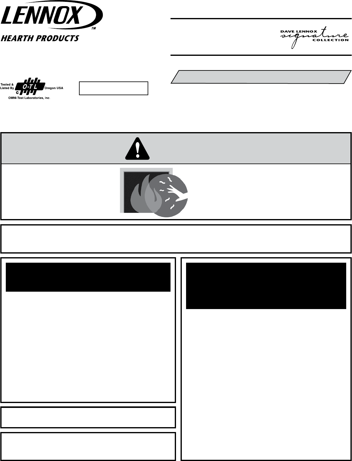
RATINGS
Model Ravelle 42
NATURAL GAS LP GAS
Max/Min Input BTUh 0-2,000 Feet (0-610 M)u
42,000 / 29,500 36,000 / 25,000
Manifold Pressure (IN. WC)
3.5 / 1.7 10 / 5.1
Min. Inlet Pressure (IN. WC)
5 11
Maximum heat output BTUs/hour-steady state
34,860 29,880
P4 Efficiency
w
50.43% 53.47%
Orifice (DMS) 0-2,000 Feet (0-610 M)u
#30 #49
uUnit factory equipped for 0-2000 FT/0-610 M, In Canada 0-4500 FT/0-1370 M
vThe Steady State Efficiency numbers based on maximum vent configuration.
wTested to CSA P.4.1-02 “Testing Method for Measuring Annual Fireplace Efficiency.
Electrical Rating: 120 VAC, 60 HZ, Less Than 2 Amps
Ductability (optional)
Forced Air Duct Kit
Whole Home Comfort
System
PRE-INSTALLATION
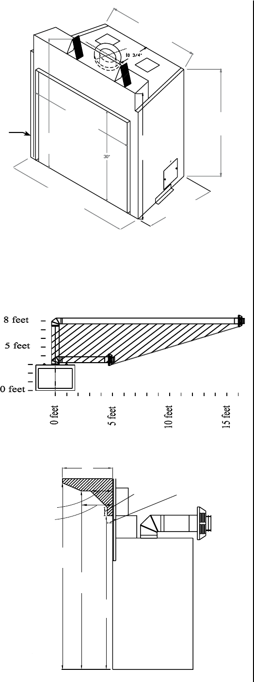
Figure 1
Figure 2
7
NOTE: DIAGRAMS & ILLUSTRATIONS ARE NOT TO SCALE.
Preparing Your Ravelle™ 42 Fireplace For Installation
Read all instructions before beginning your installation. If instructions
have not been read carefully, your installation could void your warranty
and may create a serious fire, health, or other safety hazard.
The Lennox Hearth Products warranty will be voided if one of the fol-
lowing occurs:
• Installation of any damaged fireplace or vent system compo-
nent.
• Unauthorized modification of the direct-vent system.
• Installation other than as instructed by Lennox Hearth Products,
Security™, or Simpson Dura-Vent.
• Installation of any fireplace or vent system component not manu-
factured or approved by Lennox Hearth Products, Security™ or
Simpson Dura-Vent.
When planning the installation for your Ravelle 42 gas fireplace, it’s
necessary to consider the following:
• Where the unit is to be installed
• The vent system configuration to be used
• Gas supply (NG or LP)
• Electrical wiring
• Framing and finishing
• Optional accessories
Clearances to Combustibles
Minimum clearances include any projections such as shelves, window
sills, mantels, spacers/standoffs or surfaces to combustible construction
etc. above the appliance. Paint or lacquer used to finish the mantel
must be heat resistant in order to avoid discoloration.
Minimum clearances to combustible materials in inches:
Front corners to enclosure (from stand-offs) 0 (0mm)
Rear corners to enclosure (from stand-offs) 0 (0mm)
Top to header (from stand-offs) 0 (0mm)
Bottom of unit to floor 0 (0mm)
Edge of door glass to side wall and side trim 7-1/2 (191mm)
Back to enclosure (from stand-offs) 0 (0mm)
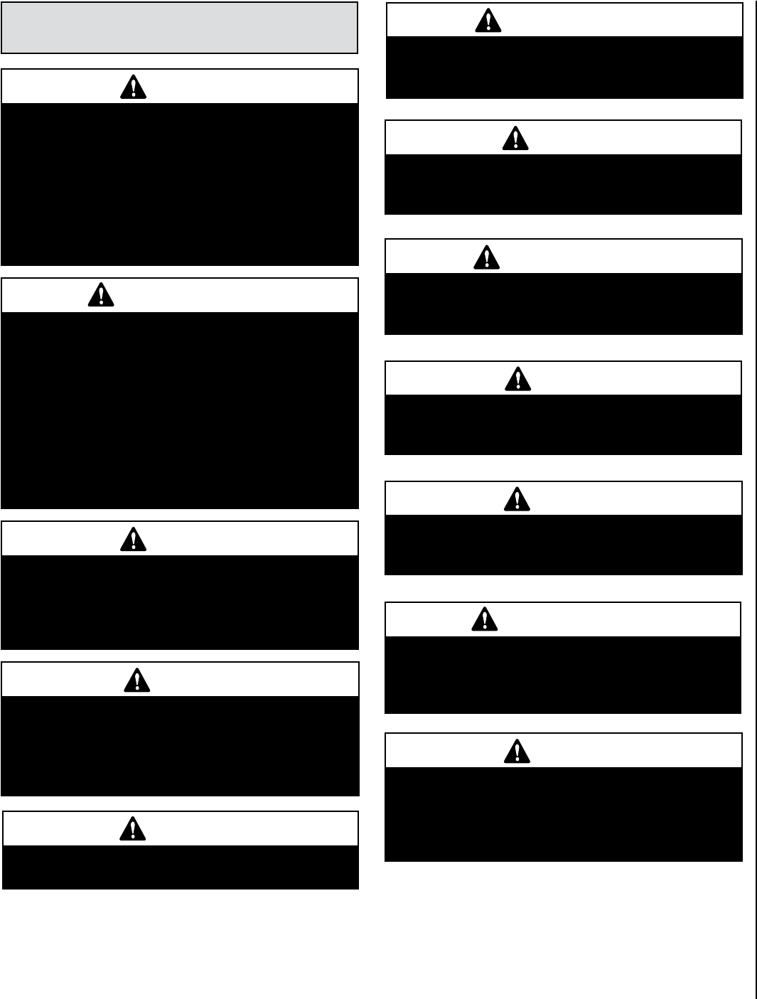
Mantel: The drawing at the lower right shows the minimum distances
from the base of the fireplace to combustible mantel and facing material.
Combustible materials may be placed above and within the shaded areas.
If your fireplace has an arched face, the combustible mantel facing mate-
rial may curve with the arch of the face as long as a minimum distance
of 10” is maintained between the top of the face and the combustible
facing material.
Hearth Protection: Hearth protection in front of the Ravelle™ 42 gas
fireplace is not required. However, hearth protection is recommended
and will enhance the appearance of the fireplace.
Pipe Clearances: All installations using a vertical termination cap
must maintain 1” (25mm) clearance between the direct-vent pipe and
combustibles. For horizontal terminations, when the top of the horizontal
run of pipe is less than 8 feet (2.4 M) above the base of the fireplace, 1”
(25mm) clearance on the sides and bottom and 5” (127 mm) on the top
of the pipe is required. For those horizontal runs at or above 8 feet, 1”
(25 mm) is required on the sides and bottom and 2” (51 mm) on the top
of the pipe. See Page 19 for allowable pipe configurations.
uThe center of the access hole for the gas piping is located at the
left side of the fireplace 6-7/8” back from the front edge and 2-1/8”
up from the base of the unit.
vThe electrical access is located at the right lower rear of the fire-
place.
w These dimensions include the 3/4” stand-offs.
*
*
Installations in the shaded
area require five inches
clearance on top of pipe.
Fireplace side view
(drawing not to scale)
Base of Fireplace
Dimensions
Mantel and Facing Material (side view)
29-3/4”
(756mm)
w
35-1/2”
(902mm)
20-3/4”
(527mm)
w
38-1/4”
(972mm)
47-3/4”
(1213mm) 41”
(1041mm)
43”
(1092mm)
12”
(305mm)
5-1/4”
(133mm)
49-5/8”
(1261mm)
47-5/8”
(1210mm)
41-5/8”
(1057mm)
7-1/2”
(191mm)
2”
(51mm) 1-1/4”
(32mm)
u
v
8NOTE: DIAGRAMS & ILLUSTRATIONS ARE NOT TO SCALE.
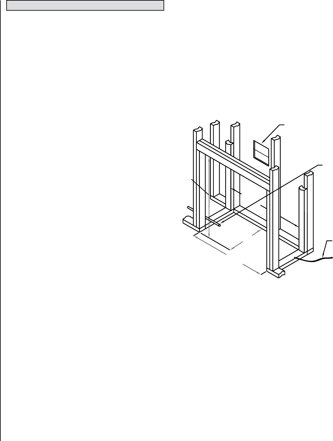
Framing Dimensions
The dimensions given on this page are minimum framing distances neces-
sary to maintain safe clearances between the Ravelle™ 42 gas fireplace
and combustible materials.
uIf the unit is to be vented horizontally with a 90º elbow right off the
top of the fireplace and directly through an exterior wall, then a hole
10-3/4” (273 mm) square with a center line 42-1/4” (1073 mm)
above the base of the fireplace will accommodate the wall thimble
and direct-vent pipe.
vThe gas line should be routed to the left side of the unit. The access
hole in the fireplace for the gas line is 6-7/8” (175 mm) back from
the front edge and 2-1/8” (54 mm) up from the base of the unit. If
the gas line enters the unit from the right side the piping will need to
be disconnected to remove the fan.
If a wall-mounted on/off switch or thermostat is to be used, these
wires should be routed to the left front of the unit for access to the
fireplace. The wire should be fed through the gas line hole, along the
gas line, to the valve.
wThe electrical power supply wiring should be routed to the right rear
of the unit.
Note: The fireplace may be placed directly on wood or non-combustible
flooring, but not on vinyl floor covering or carpet.
Framing Suggestions: The framing header above the front of the
fireplace should be as narrow front to back as allowable to give maximum
clearance to the direct-vent pipe (i.e. don’t use a 6” (152 mm) thick header
when a 4” (102 mm) thick one is allowed).
21”
(533mm)
C/L
u
v
w
44-1/2”
(1130mm)
48”
(1219mm)
44-1/2”
(1130mm)
Figure 3
A 6” (152 mm) header may need to be notched to accommodate vertical
vent pipe. If the fireplace is going to be horizontally vented directly out
the back, do not place a stud in line with the wall thimble. If a hearth
extension greater than 1” (25 mm) thick is going to be used, the fire-
place and the header must be raised accordingly. See Hearth Extension
Considerations for further details.
Insulation: The exterior walls adjacent to the fireplace should be
insulated like the rest of the house, but insulation should not be placed
around the fireplace or vent pipe.
Corner Installations: The dimensions on this page are minimum and
show the stand-offs on the rear corners of the fireplace up against the
corner walls.
INSTALLATION
9
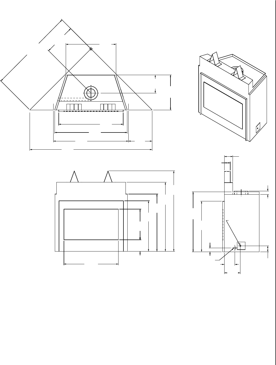
NOTE: DIAGRAMS & ILLUSTRATIONS ARE NOT TO SCALE.
Figure 4
18-9/16
(471)
14
(356)
44-1/2
(1130)
51-1/4
(1302)
29-3/4
(756)
20-3/4
(527)
47-3/4
(1213)
35-1/2
(902)
2
(51)
34
(864)
41
(1041)
38-1/4
(972)
30
(762)
43
(1092)
30
(762)
3-1/2
(89)
9-1/2
(241)
10-3/4
(273)
72-1/2
(1842)
6-7/8
(175)
18-3/16
(462)
32-5/16
(821)
3-1/2
(89)
5
(127)
6-1/4
(159)
2-1/4
(57)
GAS INLET
ELECTRICAL
INLET
Corner Installation
Framing Details
Inches (millimeters)
Fireplace Dimensions
10 NOTE: DIAGRAMS & ILLUSTRATIONS ARE NOT TO SCALE.
Base of Fireplace
One Inch Space
Fireplace
Face
Raised
Platform
Nailing
Plate
Raised Installations
The fireplace may be raised by building a platform of sufficient strength to
support the fireplace and pipe. When building a raised hearth extension,
please see the note below regarding height of the fireplace in relation to
the thickness of the hearth extension material.
Hearth Extension Considerations
A hearth extension in front of the fireplace is not required; however, to
enhance the appearance of the Ravelle™ 42 gas fireplace, one is recom-
mended. Note: There is a 1” (25 mm) space between the base of the
fireplace and the bottom of the decorative fireplace face. This space
will allow a 7/8” (22 mm) thick hearth extension (including backer board
if desired). Should a hearth extension thicker than 7/8” (22 mm) be
desired, the height of the fireplace must be raised the thickness of that
hearth extension less the 7/8” (22 mm). For example, if a 2-7/8” (73 mm)
thick cultured stone is to be placed on the floor to serve as the hearth
extension, then the fireplace must be raised 2” (51 mm) (possibly using
1/2” (13 mm) plywood over 2 x 4’s laid flat) to accommodate the 2-7/8”
(73 mm) stone. It is important to note that if the fireplace is raised then
it is necessary to raise the height of the header above the stand-offs
an equal amount. If you wish to install your fireplace without a hearth
extension you must remember to set your finished flooring height 1” (25
mm) higher than the bottom base of the fireplace or install the fireplace
1” (25mm) lower than the finished flooring materials for that room. This
will assure that no gap will exist between the room’s flooring and your
new fireplace decorative face after it is installed.
Figure 5
Figure 6
Figure 7
Fireplace
Face
Raised Platform
for Hearth Exten-
sion and Fireplace
Raised Platform
for Hearth Extension
and Fireplace
Raised
Platform Nailing
Plate
Base of Fireplace
One Inch Space
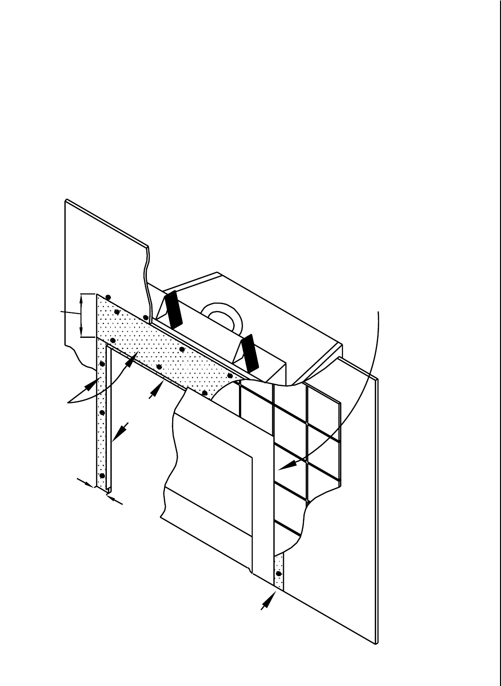
Figure 8
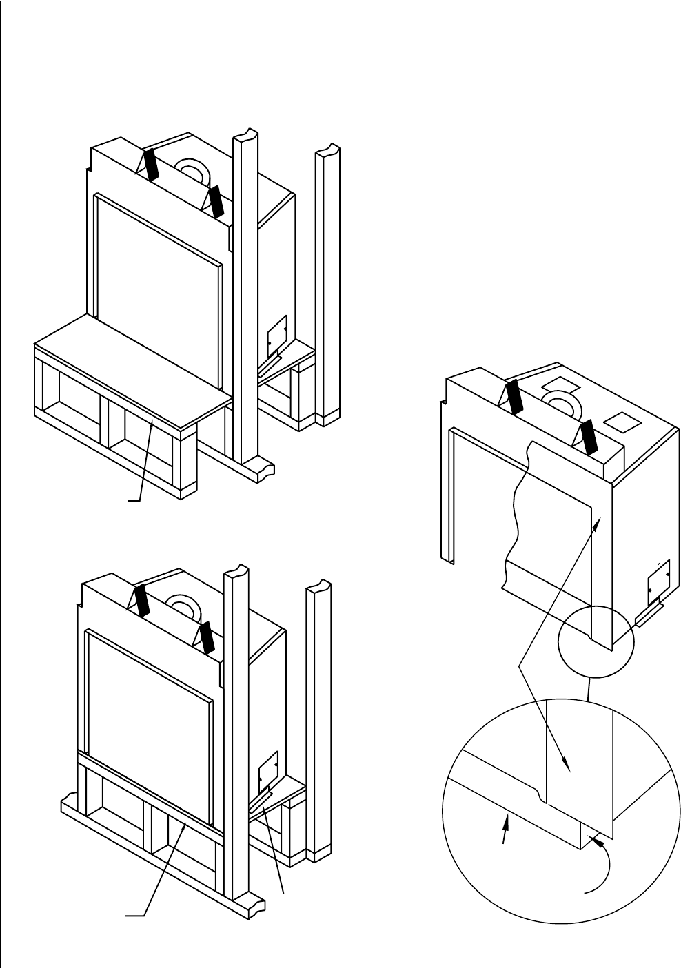
11
NOTE: DIAGRAMS & ILLUSTRATIONS ARE NOT TO SCALE.
The screws should be driven through the cement board into the outer
metal skin of the fireplace. The sheetrock (drywall) is then butted up
to the cement board. The sheetrock above the fireplace should also be
fastened to the fireplace by driving screws into the outer metal skin of
the fireplace.
Facing Less Than 1” Thick: If the combined thickness of the facing
material (eg. 3/8” [9.5 mm] thick ceramic tile and 1/2” [13 mm] thick
cement board) is less than 1” (25mm), then the tile can be placed behind
the fireplace face (see below).
Facing Installation Considerations
Non-combustible cement board (such as Wonderboard, Durock, or Har-
dybacker) must extend 10” (254 mm) above the 1” (25 mm) top reveal
and a minimum of 3” (76 mm) from each side reveal (see Figure 8). This
cement board may be 1/4” (6.3 mm) thick or greater, but would normally
be the thickness of the drywall - for example 1/2” (13 mm). The cement
board may be fastened by drywall screws.
Cement Board
3/8” Tile and 1/2” Cement
Board Behind Fireplace Face
Cement Board - a minimum
of five inches wide.
Sheetrock
1” Reveal
5” (127mm)
Minimum
Sheetrock
3” (76mm)
Minimum
Cement Board - Minimum
of 3” (76mm) Wide
10” (254mm)
Minimum
3/8” (9.5mm) Tile and 1/2” (12.7mm) Cement Board
Behind Fireplace Face
Sheetrock
Cement Board
1” Reveal
(25mm)
Sheetrock
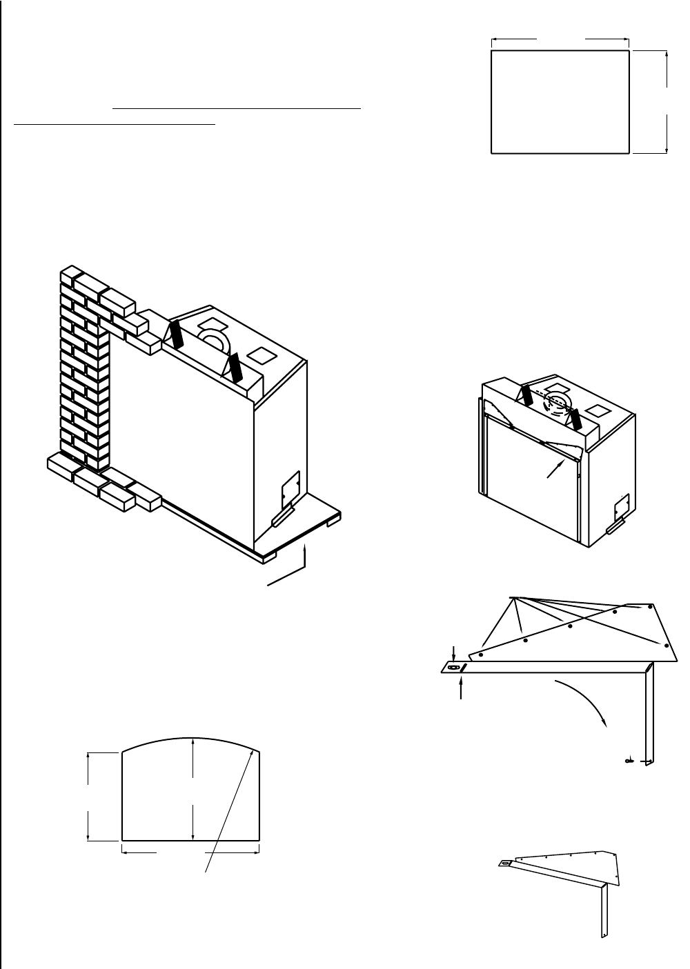
Figure 9
Figure 10 Figure 15
Figure 14
Figure 13
Figure 12
The fireplace face dimensions are:
Arch Face
Adjustment prior to arched face installation:
The corners of the 1” (25mm) reveal around the fireplace opening need
to be adjusted prior to installing an arched face (see Figures 13 and
14). Remove screws A and loosen screw B. Rotate the corner downward
bending the metal at pivot point C until the holes from which screws A
were removed line up with the lower set of holes. Reinstall screws A and
tighten screw B. When finished, the corners should look like the corner
shown in Figure 15.
Platform to raise fireplace to accommodate a
hearth extension greater than 1” in thickness.
Facing Greater Than 1” (25mm) Thick:
If the combined thickness of the facing material (eg. brick or cultured
stone) and concrete board is greater than 1”, then the facing material
must be placed around the face. A template (Arch #75098, Foundry™
#75035 and Classic [Louver] #75101) should be used while installing
the facing material. Templates for the various faces may be purchased
from your Lennox Hearth Products dealer or a template may be made of
plywood using the dimensions listed on this page. If you choose to make
a template, 1/8” (3mm) must be added to each side and top dimension
to provide sufficient clearance so the face may be removed for access to
the firebox. Since the bottom of the fireplace face is 1” above the base
of the fireplace, 1” (25mm) must be added to the height of the template
if the template is to rest on the floor or platform on which the fireplace
is placed. It is extremely IMPORTANT that the template be centered left
to right on the glass door of the fireplace.
Traditional Face
Reveal Corner Adjusted
for Arch Face
Reveal Corner Adjusted
for Arch Face
NOTE: DIAGRAMS & ILLUSTRATIONS ARE NOT TO SCALE.
26-3/8”
(670mm)
30-5/8”
(778mm)
41”
(1041mm)
51-1/2” R
(1308mm)
41”
(1041mm)
30-5/8”
(778mm)
Reveal Corner
Reveal Corner
Expanded View of
Reveal Corner
Template
Template
A
B
C
Expanded View of Reveal Corner
A
A
B
A
C
12
13
NOTE: DIAGRAMS & ILLUSTRATIONS ARE NOT TO SCALE.
2. Bracket C in the diagram below is installed on the face during the face
assembly (see instructions included with face). The captive screws D
on this bracket should be screwed into captive nuts E on the fireplace.
A phillips head screwdriver inserted through the vent holes in the face
can be used to complete this task. Align the face for plumb and level
and then tighten all four screws.
CAUTION: Any masonry that has been cleaned with an acid
wash must be properly neutralized before installing the fire-
place face. The acid wash will tarnish the face. Consult your
masonry installer.
Face Installation
A number of different faces are available for the Ravelle™ 42 gas fire-
place, however, all the faces are installed in a similar manner. A total of
four screws (two upper and two lower) attach the face to the fireplace.
To install a face:
1. Locate the two screws found in the hardware bag shipped with the face.
Position the face (with the lower door open) in front of the fireplace.
Install the two screws, A in the diagram below, through the holes in
the lower door hinge bracket and screw them into the captive nut on
tab B located on the fireplace. Do not fully tighten these screws yet.
A
B
CD
E
Expanded View
Expanded View
Figure 16
Expanded View
Expanded View
CDE
A
B

Application:
The Ravelle™ 42 gas fireplace, has been tested and listed as a direct-
vent heater system by OMNI-Test Laboratories, Portland, Oregon. and is
recommended for use with Security™ Secure Vent™ pipe.
IMPORTANT:
• Read all instructions carefully before starting the installation.
Failure to follow these instructions may create a fire or other
safety hazard and will void the warranty. Be sure to check for
specific clearances to combustible requirements on Page 7.
Do not extend the venting system vertically or horizontally in
excess of the distance prescribed on Page 19. Consult your
local building codes before beginning the installation.
• Always maintain the proper air spaces (see Page 7) between
the vent pipe and nearby combustibles to prevent a fire hazard.
Do not fill air spaces with insulation. Be sure to check the
vent termination clearance requirements from decks, windows,
soffits, gas regulators, air supply inlets and public walkways,
as specified in these installation instructions on Page 20 and
local building codes.
• This gas appliance and vent system must be vented directly to
the outside of the building and never be attached to a chimney
serving a separate solid fuel or gas-burning appliance. Each
direct-vent gas appliance must use its own separate vent system.
Common vent systems are prohibited.
• The Ravelle 42 gas fireplace is recommended for use
with Security Secure Vent pipe. The appliances and vent
manufacturers warranties will be voided and serious fire, health,
or other safety hazards may result from any of the following
actions:
• Installation of any damaged direct-vent component.
• Unauthorized modification of the direct-vent system.
• Installation of any vent component part not approved or
manufactured by the approved vent manufacturer.
• Installation other than as instructed by Lennox Hearth
Products and vent manufacturers instructions.
Vent Parts List
Direct vent pipe Security™ Secure Vent™* may be used with the Ravelle
42 gas fireplace. Please see the lists below to verify the components avail-
able from each direct-vent pipe manufacturer. Snorkel terminations are
available for applications which may require vertical rise on the building
exterior. The components listed below come in a galvanized finish. Most
of the components are also available in a painted black finish. Add a “B”
to the end of the part number when ordering if a black part is desired.
Security™ Secure Vent 6-5/8”x 4” Pipe
Part Number Description
SV4L6 6” Pipe Length
SV4L12 12” Pipe Length
SV4L24 24” Pipe Length
SV4L36 36” Pipe Length
SV4L48 48” Pipe Length
SV4LA 6” Pipe, Adjustable
SV4LA12 12” Pipe, Adjustable
SV4FA Flashing, 1/12 to 176/12 Roof Pitch
SV4FB Flashing, 8/12 to 12/12 Roof Pitch
SV4RSM Wall Radiation Shield
SV4E46 45° Elbow
SV4E90 90° Elbow
SV4VS Vinyl Shield Protector
SV4FC Storm Collar
SV4CGV Vertical Termination Cap
SV4BF Firestop
SV4CHC Horizontal Termination Cap
SV4STC36 Snorkel Termination (36”) Cap
SV4STC14 Snorkel Termination (14”) Cap
SV4BM Wall Band
Simpson DuraVent 6-5/8”x 4” GS Pipe
Part Number Description
908 6” Pipe Length
907 9” Pipe Length
906 12” Pipe Length
904 24” Pipe Length
903 36” Pipe Length
902 48” Pipe Length
911 11” to 14-5/8” Pipe, Adjustable
912 12” to 17” Pipe, Adjustable
917 17” to 24” Pipe, Adjustable
942 Wall Thimble
943 Flashing, 0/12 to 6/12 Roof Pitch
943S Flashing, 7/12 to 12/12 Roof Pitch
945 45° Elbow
950 Vinyl Siding Standoff
953 Storm Collar
963 Ceiling Firestop
980 Vertical Termination
981 Snorkel Termination (36”)
982 Snorkel Termination (14”)
984 Horizontal Square Termination (High Wind)
988 Wall Strap
991 Vertical Termination (High Wind)
14
VENT INSTALLATION

15
Vent Parts List - Horizontal
Direct vent pipe by Security™ or Simpson Dura-Vent may be used with
the Ravelle™ 42 gas fireplace. Please see the lists below to verify the
components available from each direct-vent pipe manufacturer. All
horizontally terminated venting of the Ravelle 42 gas fireplace uses 8”
x 5” size vent pipe and all vertically terminated venting uses 6-5/8” x 4”
size vent pipe. The flue collar on the fireplace is 8” x 5” in size. Therefore,
when vertically terminating it is necessary to use a reducer - part number
75247 (available from Lennox Hearth Products) - to make the transition
from the 8” x 5” flue collar to the 6-5/8” x 4” pipe. Snorkel terminations
are available for applications which may require vertical rise on the building
exterior. The components listed below come in a galvanized finish. Most
of the components are also available in a painted black finish. Add a “B”
to the end of the part number when ordering if a black part is desired.
Security™ Secure Vent™ 8”x 5” Pipe
Part Number Description
SV5L6 6” Pipe Length
SV5L12 12” Pipe Length
SV5L24 24” Pipe Length
SV5L36 36” Pipe Length
SV5L48 48” Pipe Length
SV5LA 6” Pipe, Adjustable
SV5LA12 12” Pipe, Adjustable
SV5E45 45º Elbow
SV5E90 90º Elbow
SV5RSM Wall Radiation Shield
SV5VS Vinyl Shield Protector
SV5BF Firestop
SV5CHC-1 Horizontal Termination Cap
SV5STC14 Snorkel Termination (14”) Cap
SV5STC36 Snorkel Termination (36”) Cap
SV5BM Wall Band
Simpson Dura-Vent GS 8”x 5” Pipe
Part Number Description
1208 6” Pipe Length
1207 9” Pipe Length
1206 12” Pipe Length
1204 24” Pipe Length
1203 36” Pipe Length
1202 8” Pipe Length
1211 11” to 14-5/8” Pipe, Adjustable
1217 17” to 24” Pipe, Adjustable
1290 90° Elbow
1247 Wall Thimble
1263 Ceiling Firestop
1288 Wall Strap
1281 Snorkel Termination (36”)
1282 Snorkel Termination (14”)
1284 Horizontal Termination Cap
1285 Horizontal Termination Cap (High Wind)
1250 Vinyl Siding Standoff
Vent Parts List - Vertical
Direct vent pipe by Security or Simpson Dura-Vent may be used with
the Ravelle 42 gas fireplace. Please see the lists below to verify the
components available from each direct-vent pipe manufacturer. All
horizontally terminated venting of the Ravelle 42 gas fireplace uses 8”
x 5” size vent pipe and all vertically terminated venting uses 6-5/8” x 4”
size vent pipe. The flue collar on the fireplace is 8” x 5” in size. Therefore,
when vertically terminating it is necessary to use a reducer - part number
75247 (available from Lennox Hearth Products) - to make the transition
from the 8” x 5” flue collar to the 6-5/8” x 4” pipe. Snorkel terminations
are available for applications which may require vertical rise on the building
exterior. The components listed below come in a galvanized finish. Most
of the components are also available in a painted black finish. Add a “B”
to the end of the part number when ordering if a black part is desired.
Security Secure Vent 6-5/8”x 4” Pipe
Part Number Description
SV4L6 6” Pipe Length
SV4L12 12” Pipe Length
SV4L24 24” Pipe Length
SV4L36 36” Pipe Length
SV4L48 48” Pipe Length
SV4LA 6” Pipe, Adjustable
SV4LA12 12” Pipe, Adjustable
SV4FA Flashing, 1/12 to 176/12 Roof Pitch
SV4FB Flashing, 8/12 to 12/12 Roof Pitch
SV4RSM Wall Radiation Shield
SV4E46 45° Elbow
SV4E90 90° Elbow
SV4VS Vinyl Shield Protector
SV4FC Storm Collar
SV4CGV Vertical Termination Cap
SV4BF Firestop
SV4BM Wall Band
Part Available from Lennox Hearth Products Only:
75247 8” x 5” to 6-5/8” x 4” Reducer
Simpson Dura-Vent GS 6-5/8” x 4” Pipe
Part Number Description
908 6” Pipe Length
907 9” Pipe Length
906 12” Pipe Length
904 24” Pipe Length
903 36” Pipe Length
902 48” Pipe Length
911 11” to 14-5/8” Pipe, Adjustable
912 12” to 17” Pipe, Adjustable
917 17” to 24” Pipe, Adjustable
942 Wall Thimble
945 45° Elbow
943 Flashing, 0/12 to 6/12 Roof Pitch
943S Flashing, 7/12 to 12/12 Roof Pitch
953 Storm Collar
963 Ceiling Firestop
988 Wall Strap
980 Vertical Termination Cap
991 Vertical Termination Cap (High Wind)
Vent Considerations
Twist-lock procedure: Four indentations, located on the female ends
of pipes and fittings, are designed to slide straight onto the male ends of
adjacent pipes and fittings by orienting the four pipe indentations so they
match and slide into the four entry slots on the male ends (see Figure
17). Push the pipe sections completely together, then twist-lock one sec-
tion clockwise approximately one-quarter turn until the two sections are
fully locked. The female locking lugs will not be visible from the outside
on the pipe or fittings. They may be located by examining the inside of
the female ends.
Supports: Horizontal runs of vent must be supported every three feet.
Wall straps are available for this purpose.
Pipe Sealing: If Security™ Secure Vent™ pipe is used, then sealant is
required at only the first pipe joint attaching the pipe to the flue collar on
the fireplace. If Simpson Dura-Vent GS pipe is used, then the pipe must
be sealed as follows: seal both the inner and outer pipes with a high
temperature silicone sealant rated for at least 600º F (commonly known
as “RTV”). Run a 1/8” (3mm) bead of silicone around the outside of the
male end of the outer sleeve. Run a 1/8” (3mm) bead of silicone about
1/4” (6mm) from the end of the male inner pipe, which is found in the
pipe to be attached above. Twist-lock the pipes or fittings together.
Figure 17
Sealant
Female
Locking
Lugs
Male
Locking
Lugs
16 NOTE: DIAGRAMS & ILLUSTRATIONS ARE NOT TO SCALE.

Figure 18 17
NOTE: DIAGRAMS & ILLUSTRATIONS ARE NOT TO SCALE.
Horizontal Vent Installation
IMPORTANT NOTES:
1. All Ravelle™ 42 gas fireplaces horizontally terminated vent
installations use 8”x 5” Security™ Secure Vent™ or Simpson
Dura-Vent GS direct-vent pipe.
2. When this pipe passes through a wall, a wall thimble - Security
#SV5RSM or Simpson #1247 is required. The hole in the wall
for the wall thimble should be 10-3/4” x 10-3/4”.
3. Horizontal runs of vent must be supported every three feet.
Wall straps - Security #SV5BM or Simpson #1288 are available
for this purpose.
4. If the vent passes through a ceiling or floor, a firestop - Security
#SV5BF or Simpson #1263 is required.
5. Venting terminals shall not be recessed into a wall or siding.
If installing the termination cap on a wall covered with siding,
a vinyl siding standoff - Security #SV5VS or Simpson #1250
or furring strips must be used to ensure that the termination
cap is not recessed into the siding.
6. The horizontal run of vent must have a 1/4” (6mm) rise for
every 12” (305mm) of run towards the termination.
7. If the wall being penetrated is constructed of non-combus-
tible material, such as masonry block or concrete, an 8-1/2”
(216mm) diameter hole is acceptable and a wall thimble is
not required.
8. The location of the horizontal vent termination on an exterior
wall must meet all local and national building codes and must
not be blocked or obstructed. For allowable external vent
terminations locations, see the diagram on Page 20.
9. Allowable clearances from the vent pipe to combustible materi-
als must be maintained. See Page 7 for these clearances.
10. Do not locate the termination cap where it may be blocked by
shrubbery or snow.
Vertical Vent Installation
IMPORTANT NOTES:
1. All Ravelle 42 gas fireplace vertically terminated vent installations
use 6-5/8” x 4” Security or Simpson Dura-Vent GS direct-vent
pipe.
2. Fireplaces that are vertically terminated require pipe reducer
- Lennox Hearth Products #75247 - installed on the fireplace’s
flue collar before the
direct-vent pipe can be installed.
3. If the vent passes through a ceiling or floor, a firestop - Security
#SV4BF or Simpson #963,
4. If the vent passes through the roof, a roof flashing - Security
#SV4FA or SV4FB, Simpson #943 or 943S and storm collar
- Security #SV4FC, Simpson #953 are required.
5. Allowable clearances from the vent pipe to combustible materi-
als must be maintained. See Page 7 for these clearances.
6. A maximum of two 45º elbows may be used. See Page 19 for
allowable offsets.
7. The maximum system height is 30 feet (9.1 M) and the minimum
is 10 feet (3 M).
Note:
Verify that you have
at least the mini-
mum clearance to
combustibles at the
roofline.
Flashing
Simpson (Part # 943 or 943S)
Secuirty (Part #SV4FA or SV4FB)
Vertical Termination Cap
Security (Part #SV4CGV)
Simpson (Part # 980)
Pipe
Length
Ceiling Firestop
Simpson (Part # 963)
Security (Part # SV4BF)
Ceiling Minimum
Framing 10” x 10”
(254mm x 254mm)
Storm Collar
Simpson (Part # 953)
Security (Part #SV4FC)
Roof- Maintain 1”
(25mm) Clearance
to Combustibles
Figure 19
10-3/4”x 10-3/4”
(273mm x 273mm)
Framed Hole
Termination Cap
Wall Thimble
Elbow

18
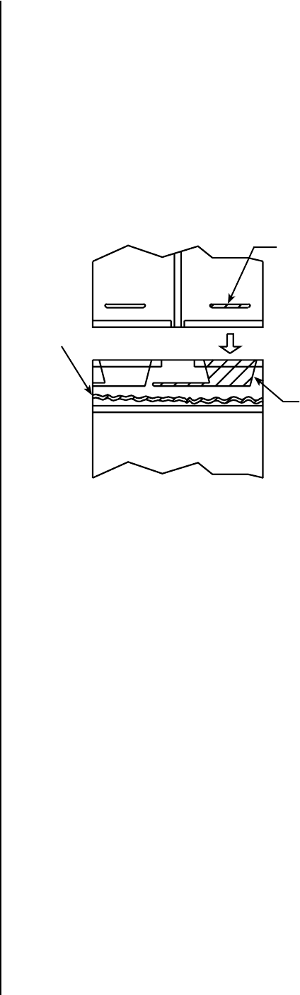
Flue Restrictors
The flue restrictor settings shown in Figures 22 and 23 are for typical
installations and may need to be adjusted from standard to take into
account other variables in the installation to achieve proper combustion.
See Flue Restrictor Guidelines on this page to assist you in making a
proper flue restrictor adjustment.
The Ravelle™ 42 gas fireplace uses balanced flue technology to ensure
proper combustion. Flue restrictors may need to be installed depending
on the vent configuration of your fireplace. The drawings on Page 19
show all the allowable pipe configurations for the Ravelle 42 gas fireplace.
To properly install the flue restrictor, find your pipe configuration in the
drawings on Page 19 and note which restrictor setting is recommended.
The flue restrictors and four black self-tapping 5/32” allen head screws
can be found in the firebox in a plastic bag. The restrictors should be
placed over the openings at both sides of the ceiling of the firebox. For
each restrictor, two self-tapping 5/32” allen head screws should be in-
stalled in either holes 1, 2, 3, or 4 in the restrictor and screwed into the
two holes in the firebox ceiling. (There are four holes at each side of the
firebox ceiling to receive only two screws. Insert the screws into either
two holes). See the drawing to the right for the location of hole numbers
on the restrictor. The numbered holes in which the screws are inserted
in the restrictor should correspond to the restrictor position numbers
found on the drawings for your pipe configuration. Restrictor positions
are based on tests run in a laboratory. The optimum restrictor positions
may need to be adjusted slightly depending on the conditions surround-
ing the residential installation. Do not adjust restrictors to a point where
the fireplace is sooting.
Notes: The higher the number of the flue restrictor position, the greater
amount of combustion air will be delivered.
Flue Restrictor Adjustment Guidelines
After the flue restrictors have been set to the standard settings as shown
in Figures 22 and 23, the burner flame appearance should be evaluated
to determined if the flue restrictors need to be set to a different position
to adjust for variables in your installation. Light the appliance and allow
it to burn for 20 minutes. See Flame Color and Behavior on Page 31 to
determine if you have a proper burner flame appearance. If the proper
flame appearance cannot be achieved, the flue restrictor may need to be
set to a different position. See the following guidelines to determine if
you need to readjust the flue restrictors.
Before proceeding, confirm the manifold and inlet gas pressure is correct,
primary air shutter is properly adjusted, venting system connections are
secure and not blocked and if you are at a high elevation, ensure unit has
been properly derated:
Symptoms - Lack of Combustion Air
If the symptoms listed below are present, you may need to adjust the
flue restrictor to a more open position.
• Flame appears yellow
• Floating Flames (lazy, ill defined, quiet, may roll)
• Sooting
• Pilot becomes yellow and appliance shuts down
Symptoms - Excessive Combustion Air
If the symptoms listed below are present, you may need to adjust the
flue restrictor to a more closed position.
• Low Flame
• Pilot pulls and appliance shuts down
• Pilot flame ghosts
Termination Heights For Vents
Above Flat Or Sloped Roofs
Ref. NFPA 54 / ANSI Z223.1
Roof Pitch * Feet * Meters
Flat to 6/12 1.0 0.3
6/12 to 7/12 1.25 0.38
7/12 to 8/12 1.5 0.46
8/12 to 9/12 2.0 0.61
9/12 to 10/12 2.5 0.76
10/12 to 11/12 3.25 0.99
11/12 to 12/12 4.0 1.22
12/12 to 14/12 5.0 1.52
14/12 to 16/12 6.0 1.83
16/12 to 18/12 7.0 2.13
18/12 to 20/12 7.5 2.29
20/12 to 21/12 8.0 2.44
12
X
Roof Pitch is X/12
2 FT
MIN.
2 FT MIN.
Lowest
Discharge
Opening
H*
*H = MINIMUM HEIGHT FROM ROOF TO
LOWEST DISCHARGE OPENING OF VENT
TERMINATION HEIGHTS FOR VENTS ABOVE
FLAT OR SLOPED ROOFS
Horizontal Overhang
Vertical
Wall
Vent
Termination
Storm Collar
Concentric
Vent Pipe
Flashing
1 inch (25.4 mm) Minimum
Clearance to Combustibles
Vertical Vent Termination Clearances
The vent / air intake termination clearances above the high side of an
angled roof is as shown in the table below.
Figure 20
NOTE: DIAGRAMS & ILLUSTRATIONS ARE NOT TO SCALE.
Figure 21
Restrictors
Interior of Firebox
Restrictors
Interior of Firebox
19
NOTE: DIAGRAMS & ILLUSTRATIONS ARE NOT TO SCALE.
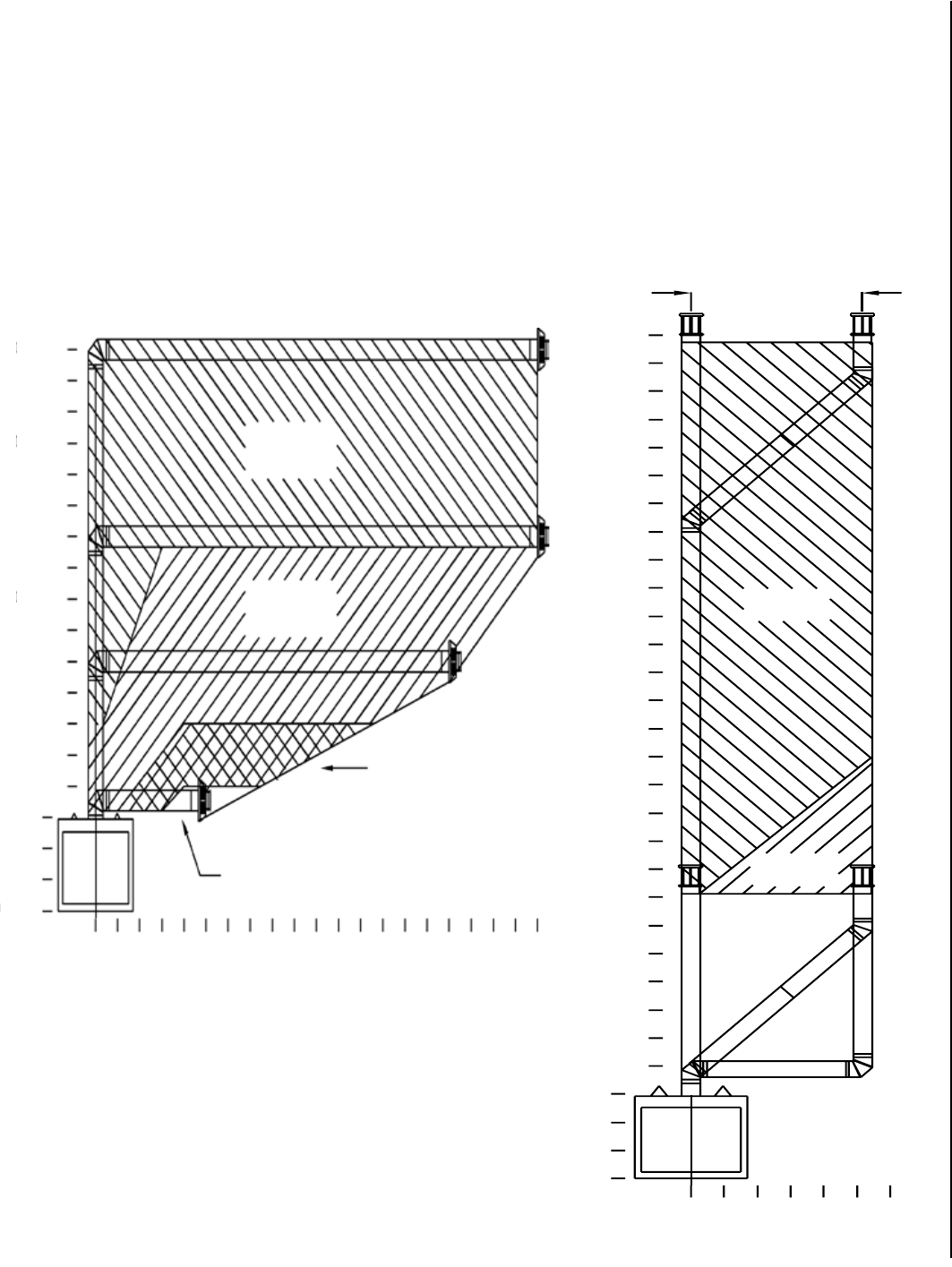
Vertical Terminations
(Use 6-5/8” Direct-Vent Pipe)
The shaded areas in the diagram below show all allowable combinations
of straight vertical and offset to vertical (maximum four 45º elbows or two
90º elbows) vent configurations with vertical terminations. The termina-
tion must fall within the shaded areas on the diagram. Use the restrictor
positions indicated. The maximum offset length at a 45º angle consists
of one three foot and one four foot section of pipe. The maximum height
is 30 feet (9.1 M) and the minimum is 10 feet (3 M).
Vertical Terminations
Restrictor
Position #2
5 Ft. 2 In. (1.6M)
Maximum
Restrictor
Position #1
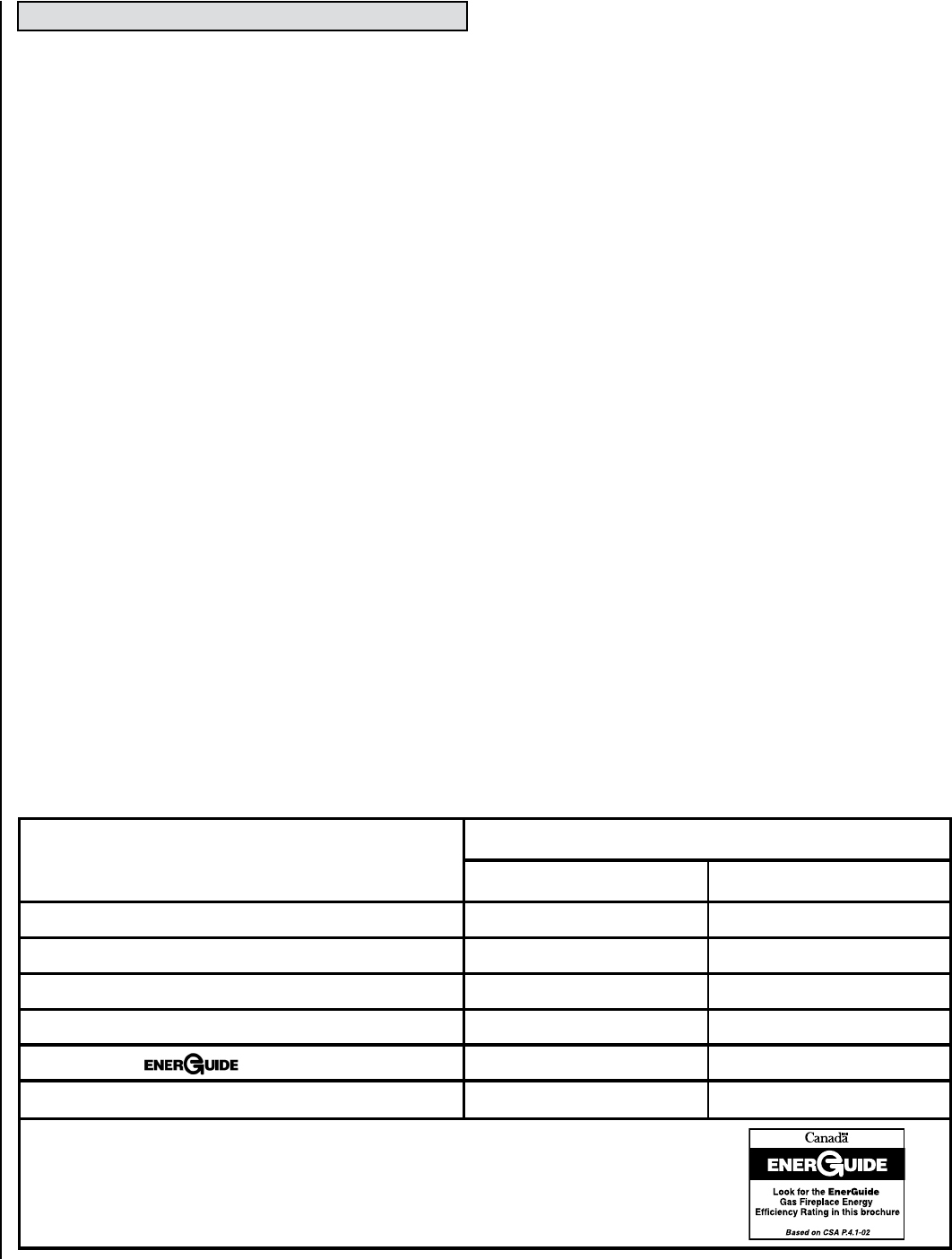
Horizontal Terminations
(Use 8” Direct-Vent Pipe)
The shaded areas in the diagram below show all allowable combinations
of vent configuration with horizontal terminations. Horizontal sections
of pipe require 1/4” (6.4 mm) of rise for every 12” (305 mm) of run.
A second 90º or 45º elbow (in addition to the first 90º elbow at the top
of the vertical length of pipe) is allowed as long as the overall length of
the horizontal run of pipe does not exceed those shown below. Use the
restrictor positions indicated. If the fireplace is vented with an elbow
directly off the top of the flue collar and three to four feet of horizontal
pipe is used, then no restrictor is to be installed in the fireplace.
Horizontal Terminations
Restrictor
Position #2
Restrictor
Position #3
Restrictor Position #4
No Restrictor
Snorkel Terminations: For installations requiring a vertical rise on the exterior
of the building, 14-inch (356 mm) and 36-inch (914 mm) tall snorkel terminations -
Security™ #SV5STC14 or SV5STC36 and Simpson #1281 or 1282 are available. Follow
the same installation procedures as used for standard horizontal terminations. If the
snorkel termination must be installed below grade (i.e. basement application), proper
drainage must be provided to prevent water from entering the snorkel termination.
Do not attempt to enclose the snorkel within the wall or any other type of enclosure.
On vinyl siding, furring strips may be used to ensure that the snorkel is not recessed
into the siding. NEVER install the snorkel upside down.
18 Ft.
(5.5M)
15 Ft.
(4.6M)
10 Ft.
(3M)
5 Ft.
(1.5M)
0 Ft.
(0M)
0 Ft.
(0M) 5 Ft.
(1524M) 10 Ft.
(3M) 15 Ft.
(4.6M) 20 Ft.
(6M)
15 Ft.
(4.6M)
20 Ft.
(6M)
5 Ft.
(1524M)
0 Ft.
(0M)
0 Ft.
(0M) 5 Ft.
(1524M)
10 Ft.
(3M)
30 Ft.
(9M)
25 Ft.
(7.6M)
Figure 22
Figure 23
20 NOTE: DIAGRAMS & ILLUSTRATIONS ARE NOT TO SCALE.
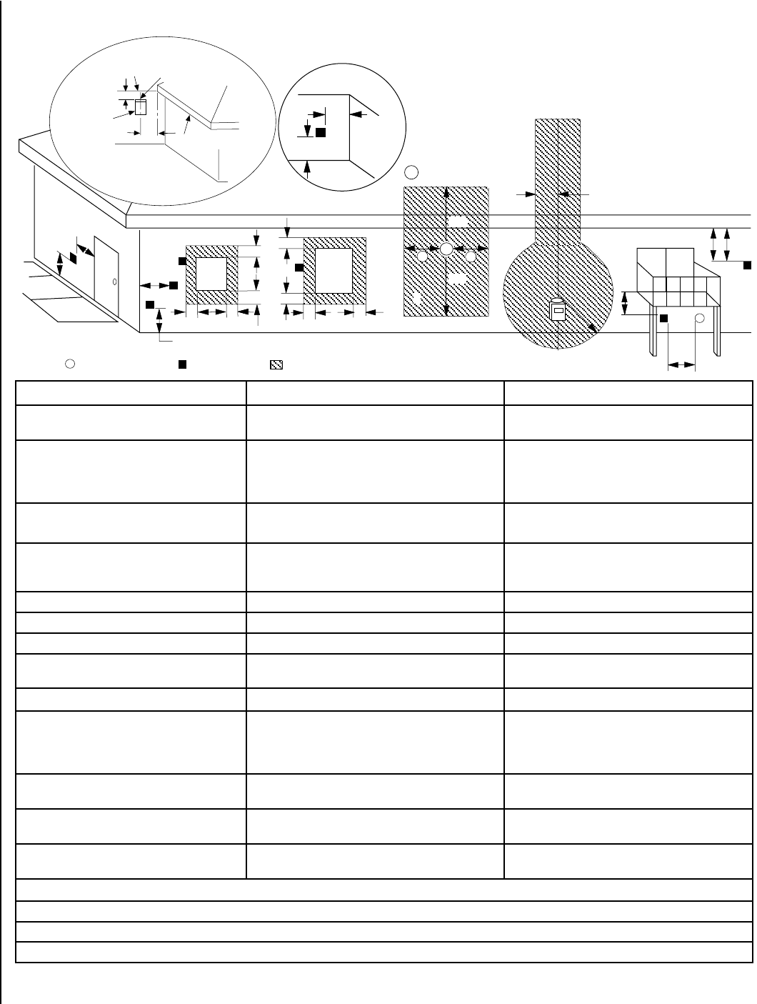
Exterior Horizontal Vent Termination Clearance Requirements
V
V V
V
V
F
C
B
B
A
B
H
M
I
X V
D
V
A A
A
V
L
B
J
X E
V
A
G
*18”
18”
B
C
C
C
�
�
�
K
X
* See Item D in the Text Below.
Center Line
of Termination
Exterior Wall
Horizontal
Termination
Ventilated Soffit
Inside Corner
DETAIL D
Minimum Clearances Canadian Installation * US Installation **
A = Clearance above grade, veranda, porch, deck
or balcony.
12 inches (30 cm) * 12 inches (30 cm) **
B = Clearance to window or door that may be
opened.
6 in. (15.2 cm) for appliances < 10,000 BTU/hr (3kW),
12 in. (30 cm) for appliances > 10,000 BTU/hr (3kW) and <
100,000 BTU/hr (30kW), 36 inches (91 cm) for appliances
> 100,000 BTU/hr (30kW)*
6 in. (15.2 cm) for appliances < 10,000 BTU/hr (3kW),
9 in. (23 cm) for appliances > 10,000 BTU/hr (3kW) and <
50,000 BTU/hr (15kW), 12 inches (30 cm) for appliances
> 50,000 BTU/hr (15kW)*
C = Clearance to permanently closed window 12 inches (305 mm) recommended to prevent window
condensation
9 inches (229 mm) recommended to prevent window
condensation
D = Vertical clearance to ventilated soffit located
above the terminal within a horizontal distance of 18
in. (458 mm) from the center line of the terminal
18 inches (458 mm) 18 inches (458 mm)
E = Clearance to unventilated soffit 12 inches (30 cm) 12 inches (30 cm)
F = Clearance to outside corner 5 inches (12.7 cm) 5 inches (12.7 cm)
G = Clearance to inside corner 6 in. (15 cm) 6 in. (15 cm)
H = Clearance to each inside of center line extended
above meter / regulator assembly
3 feet (91 cm) within a height of 15 feet above the meter /
regulator assembly *
3 feet (91 cm) within a height of 15 feet above the meter
/ regulator assembly **
I = Clearance to service regulator vent outlet 3 feet (91 cm) * 3 feet (91 cm) **
J = Clearance to non-mechanical air supply inlet
to building or the combustion air inlet to any other
appliance
6 in. (15.2 cm) for appliances < 10,000 BTU/hr (3kW), 12
in. (30 cm) for appliances > 10,000 BTU/hr (3kW) and <
100,000 BTU/hr (30kW), 36 inches (91 cm) for appliances
> 100,000 BTU/hr (30kW)*
6 in. (15.2 cm) for appliances < 10,000 BTU/hr (3kW), 9
in. (23 cm) for appliances > 10,000 BTU/hr (3kW) and <
50,000 BTU/hr (15kW), 12 inches (30 cm) for appliances
> 50,000 BTU/hr (15kW)*
K = Clearance to mechanical air supply inlet 6 feet (1.8 meters) * 3 feet (91 cm) above, if within 10 feet (3 m) horizon-
tally**
L = Clearance above paved sidewalk or paved
driveway located on public property
7 feet (2.13 m) ‡ 7 feet (2.13 m) ‡
M = Clearance under veranda, porch, deck or
balcony
12 in. (30 cm) * ‡ 12 in. (30 cm) ** ‡
* In accordance with the current CSA/CAN-B149.1 National Gas and B149.2 Propane Installation Code - Latest Editions.
** In accordance with the current ANSI Z223.1 / NFPA 54 National Fuel Codes - Latest Edition.
‡ A vent shall not terminate directly above a sidewalk or paved driveway which is located between two single family dwellings and serves both dwellings.
*‡ Only permitted if veranda, porch, deck or balcony is fully open on a minimum 2 sides beneath the floor.
Inside
Corner Detail
Operable
Window
Fixed
Closed
Window
= 9" in U.S.
= 12" in Canada
3 ft.
3 ft.
= Air Supply Inlet = Vent Terminal = Area where Terminal is NOT permitted
Figure 24
21
NOTE: DIAGRAMS & ILLUSTRATIONS ARE NOT TO SCALE.
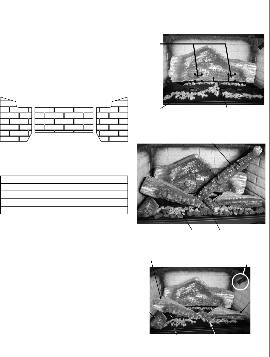
Log Installation Instructions
If logs are not installed according to the log installation instructions,
flame impingement and improper combustion could occur and result
in soot and/or excessive production of carbon monoxide (CO), a color-
less, odorless, toxic gas.
The size and position of the log set is critical to achieve a safe, reli-
able and attractive flame pattern. Any attempt to use a different log
set in the fireplace will void the warranty and will result in incomplete
combustion, sooting and poor flame quality.
1. Remove the six logs from the box and foam packaging. Lay them out
for easy identification during installation.
2. Place rear log on insert tabs (these tabs will penetrate the center of
the log) at the rear of the burner.
3. Place a light (fluffed) layer of embers (rockwool) directly on top of
the port holes in the burner. CAUTION: A 1/4” (6.4mm) air space
between the rockwool and lower base of the rear log needs to be
maintained for combustion air and proper flame aesthetics.
4. Place Log #2 on tab. An air shield is provided for natural gas use only.
For LP conversions, remove the air shield.
5. Place Logs #3, #4 and #5 on tab inserts.
Important!!! Maintain a 1/4” (6.4mm) air
space along the entire length of log.
Rockwool
Insert
Tabs
Log #3
Log
#4
Log
#2
Log #5
Air Shield
Log Locater
Tab for Log #6
Log #6
Embers
Brick Panel and Log Set Installation
Brick Panel
The brick panels are extremely fragile so handle them with care.
1. Remove brick panels from box and wrapping.
2. The long rectangular panel goes in the rear of the firebox - the thin layer
of bricks should be down. The panel rests on three metal tabs protruding
from the rear of the firebox about 3” above the firebox floor.
3. On the side panels, the rounded edge goes to the front. Install the side
panels by sliding them along the side of the firebox into retainers at
the top and bottom.
Figure 25
Figure 26
Figure 27
Figure 28
Volcanic Stone
6. Place Log #6 on tab located on right side of firebox. The other end of
the log is placed on the burner.
7. Volcanic stone may be placed along the front edge of the burner, but
not directly over the burner ports.
Firebox Accessories / Parts
Cat. No. Description
H5859 Log Set
H5863 Bag of Embers (volcanic stone)
H5864 Bag of Rockwool (glowing embers)
Log Set and Embers
22
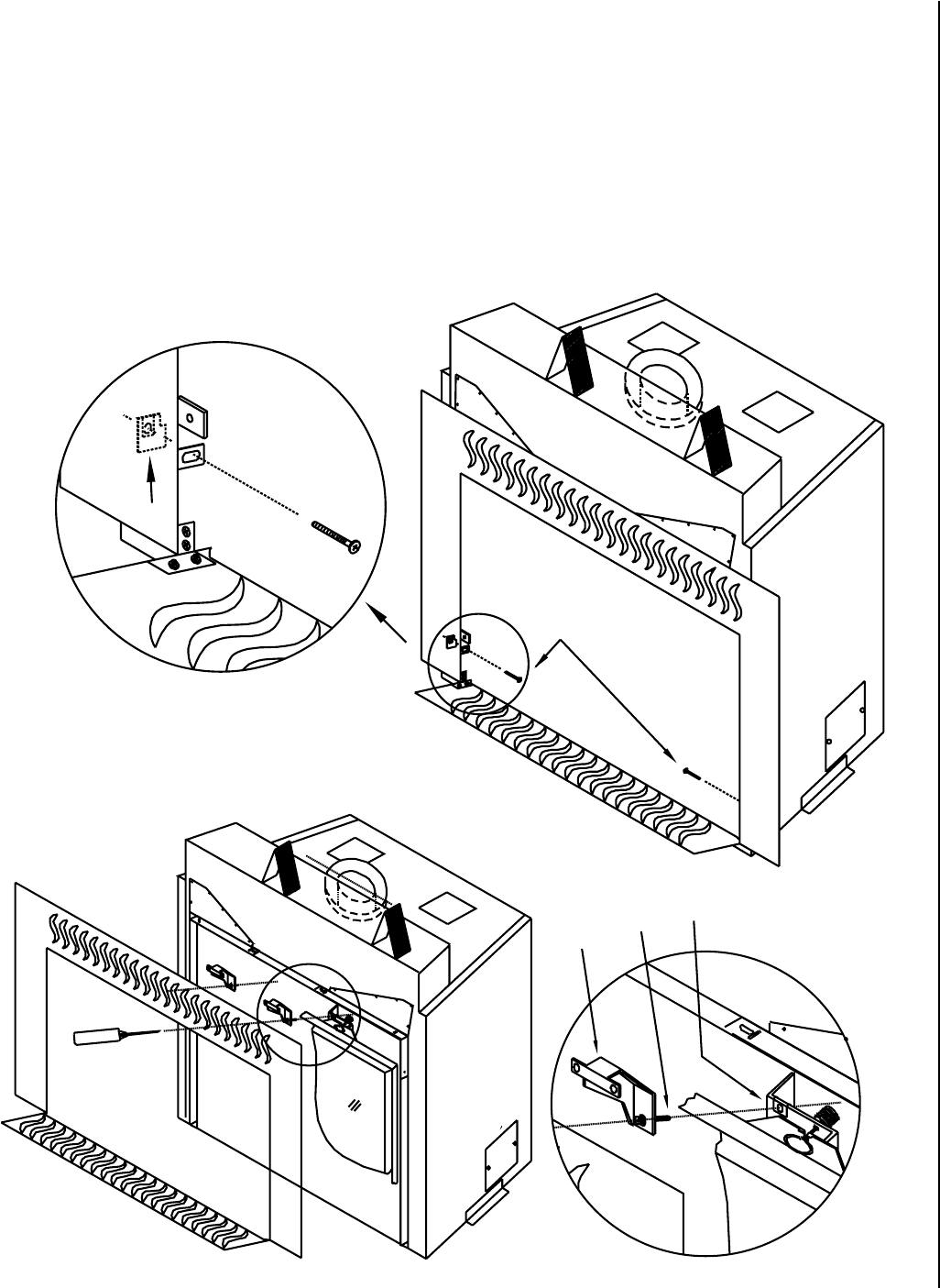
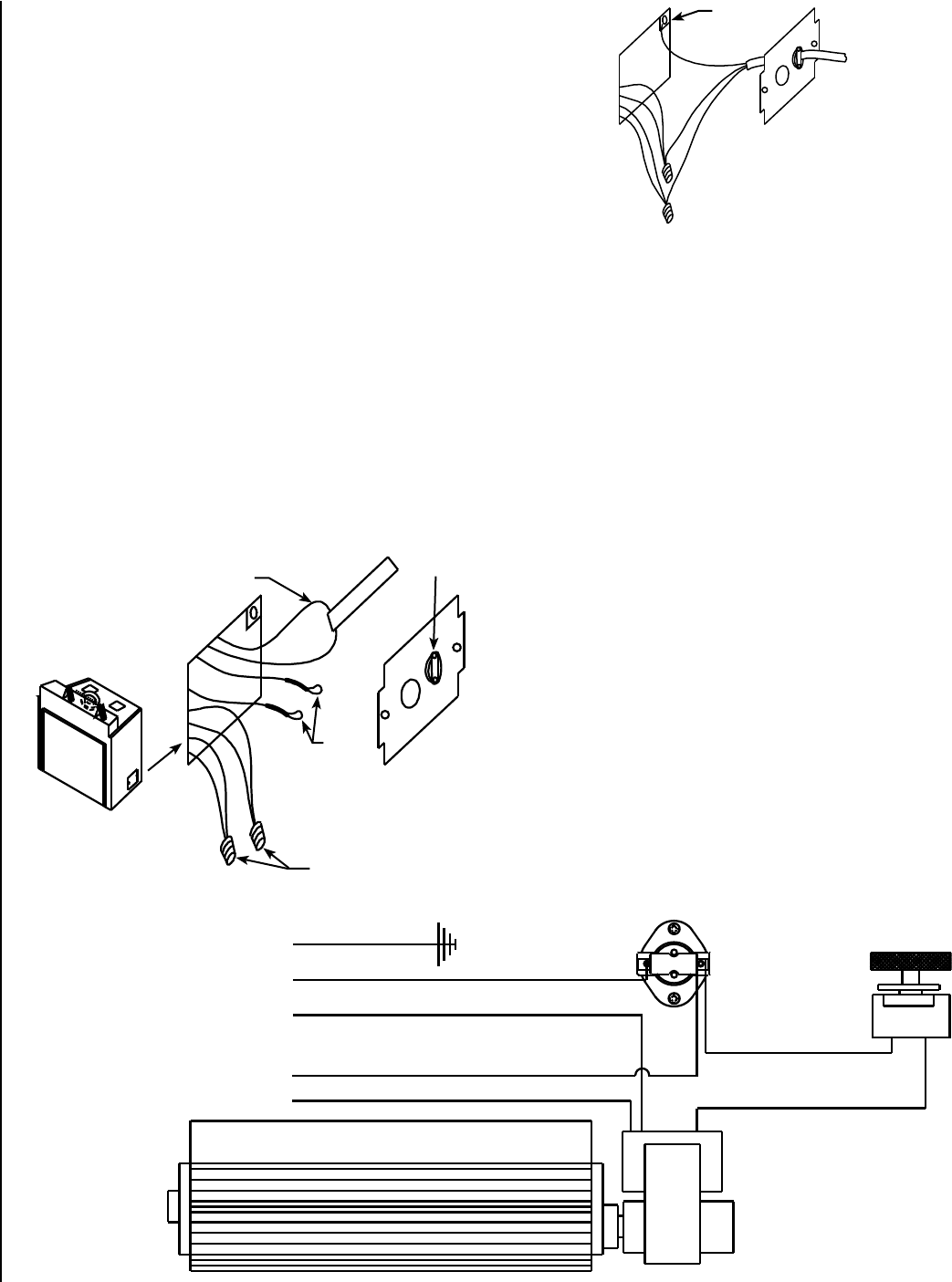
Electrical Connections:
* The breaker supplying electricity to the fireplace must be turned off at the
electrical panel before any connections are made at the fireplace.
* The wire supplying the fireplace should be a minimum of 14 gage and
provide 120 Volts at 60 hz.
* The fireplace must be grounded in accordance with local electrical
codes or, in the absence of local codes, with the National Electrical
Code or ANSI/NFPA 70 - latest edition.
* The electrical box is located at the right rear of the fireplace (see Figures
29 and 30). Remove the cover, loosen the wire clamp A and feed the
household supply line through the clamp and retighten clamp.
* Connect the supply ground wire to the green screw B.
* Remove the wire nut C from the black wires coming from the fireplace
and join these wires to the black supply wire reusing the wire nut.
Repeat for white wires.
* Reinstall the cover to the fireplace.
* If a wall-mounted burner on/off switch or thermostat is to be used,
the wires running from the switch or thermostat should be routed to
the left side of the fireplace. The wire should be fed through the gas
line supply hole along the gas line to the valve.
CAUTION: Label all wires prior to disconnection when servic-
ing controls. Wiring errors can cause improper and dangerous
operation.
ATTENTION: Au moment de l'entretien des commandes,
étiquetez tous les fils avant de les débrancher. Des erreurs
de cáblage peuvent entraîner un fonctionnement inadéquat et
dangereux.
Wall-Mounted Fan Speed Control:
If desired, a wall-mounted fan speed control can be installed. The breaker
supplying electricity to the fireplace must be turned off at the electrical
panel before any connections are made. The loop of wire with the label
attached (E in Figure 29) may be cut and the wire leads from the wall-
mounted speed control connected to each end of the cut wire.
Optional Heat Ducting System:
The remaining red and white wires with capped ends (wires D in Figure
29) are for the optional Forced Air Heating System. See the instructions
provided with the system for installation details.
Blower Removal:
Disconnect the power supply at the household electrical panel prior to
blower removal. The blower can be accessed through the lower door on
the fireplace face.
See Figure 31 for the fan wiring diagram, for reference. The blower is
located at the rear of the open area beneath the firebox. (During instal-
lation of the fireplace, if the gas line was fed in from the right side it will
now need to be removed). To remove the blower, disconnect the wiring
by pulling the two spade connectors loose at the blower motor. The
blower rests on two pins - one located at each end of the blower. Grasp
the blower assembly at each end and pull the blower forward off the two
pins. (If the blower assembly is pulled from the center, it may distort the
assembly). The blower can then be carefully pulled out from under the
fireplace. To install the blower repeat the steps in the reverse order. There
is a rubber grommet at each end of the blower assembly which slides
over the pins supporting the blower. Make sure these grommets are in
place when reinstalling the blower.
Figure 29
Figure 30
Figure 31
L
a
be
l
L
a
b
e
l
D
A
C
E
B
Fan Wiring Diagram
Green (Ground)
Snap Switch (Contacts Close When Fireplace is Hot)
Black (Hot)
From Power Source
Speed Control
White (Neutral)
Black
Black
Red
White
Blower
To Optional Heat Duct Fan
NOTE: DIAGRAMS & ILLUSTRATIONS ARE NOT TO SCALE.
23
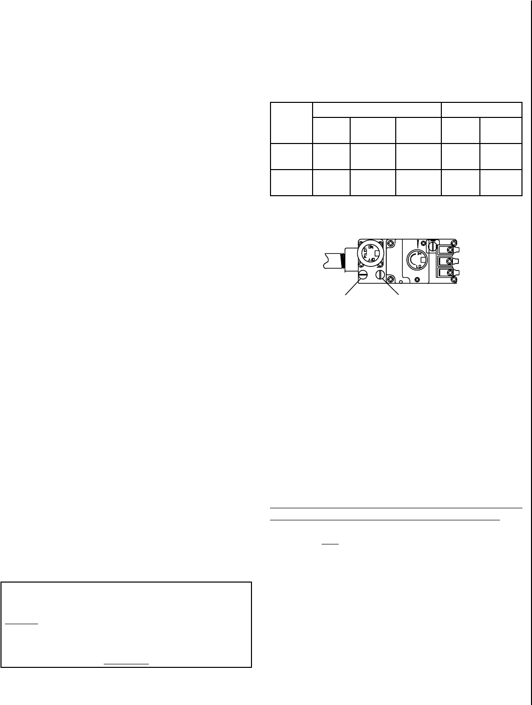
Fuel
Type
Inlet Pressure Manifold Pressure
Desired Minimum Maximum On Hi
Fire
On Lo
Fire
Natural
Gas
7" WC 5" WC 10.5" WC 3.5" WC 1.7" WC
LP Gas 11" WC 11" WC 13" WC 11" WC 5.4” WC
Gas Line Installation
The Ravelle™ 42 gas fireplace must be connected to the gas line in ac-
cordance with local codes and/or the National Fuel Gas Code, ANSI Z223.1
(In Canada, the current CAN/CSA B149.1 installation code). The gas line
should enter the fireplace on the left side (see diagrams on Pages 8 and
9). If the gas line enters the unit from the right side, the line will need to
be disconnected to remove the fan. The fireplace comes with a flex line
attached to the supply side of the gas valve. The fitting on the end of the
flex line can receive a 1/2” female iron pipe coupling, a 3/8” male iron
pipe, or a shut-off valve. There is sufficient room to locate the shut-off
valve under the firebox at the end of this flex line, however, local codes
may require the shut-off to be located on the exterior of the fireplace. After
connecting the gas line, all joints in the line and connections at the valve
should be checked for leaks before final positioning of the unit. Conduct a
gas leakage test of the appliance piping and control system downstream
of the shutoff valve in the supply line to the appliance.
Gas Pressure Requirements
A MAJOR CAUSE OF OPERATING PROBLEMS WITH GAS APPLI-
ANCES IS IMPROPER GAS PRESSURE!
The most important item to check during the initial installation
and the first thing to check when operating problems occur is
gas pressure!
This fireplace will not function properly unless the required
gas pressure is supplied. See the table on this page for gas
pressure requirements.
Two pressure taps are provided on the fireplace’s valve to check gas
pressures. To access the taps remove the two socket head screws to
remove the valve control panel/heat shield. The taps are located below
the on/off/pilot knob (see Figure 32). The left tap is the inlet (supply)
pressure side. To check inlet pressure (with the fireplace burning) insert
a small flat bladed screwdriver into the tap and turn a half turn counter-
clockwise. Cover the tap with the line from a manometer and read the
pressure. Close the tap gently but securely after completing the check.
The manifold (outlet) tap is to the right of the inlet tap. To check manifold
pressure (with the fireplace burning at the high burn setting) insert a
small flat bladed screwdriver into the tap and turn a half turn counter-
clockwise. Cover the tap with the line from the manometer and check
the pressure. Again close the tap gently but securely after completing
the check. Check the taps for gas leaks with a gas leak test solution
(retighten if necessary).
If the pressure is not sufficient, make sure the gas supply line is large
enough, the supply regulator is properly adjusted and the total gas load
for the residence does not exceed the amount supplied.
Propane tanks are at pressures that will cause damage to valve com-
ponents. Verify that the tanks have step down regulators to reduce the
pressure to safe levels.
LP and Natural Gas Supplies
Your Ravelle gas fireplace is equipped from the factory for use with
natural gas only as specified on the Safety / Listing label attached to the
appliance. This appliance can only be operated using propane gas (LP)
if a certified fuel conversion kit provided by Lennox Hearth Products is
installed by a qualified service technician.
Also check the orifice size on the label on the igniter bracket. It must be
the correct size for the fuel and altitude.
Do not run propane tank dry. Running the tank dry may cause a
hazardous condition due to pressure drop in empty tank.
Solid fuel is NOT to be used with this unit.
Note: The appliance and its individual shut-off valve must be disconnected
from the gas supply piping system during any pressure testing of that
system at test pressures in excess of 1/2 psig. The appliance must be
isolated from the gas supply piping system by closing its individual
manual shut-off valve during any pressure testing of the gas supply piping
system at test pressures equal to or less than 1/2 psig. Check with your
gas supplier or plumber.
Inlet (Supply)
Pressure Tap
Figure 32
The Manifold
(Outlet) Tap
TP/TH
TH
TP
SIT Millivolt Gas Valve
These appliances must be isolated from the gas supply piping system
(by closing their individual manual shut-off valve) during any pressure
testing of the gas supply piping system at test pressures equal to or
less than 1/2 psig (3.5 kPa).
These appliances and their individual shut-off valves must be discon-
nected from the gas supply piping system during any pressure testing
of that system at pressures greater than 1/2 psig (3.5 kPa).
NOTE: DIAGRAMS & ILLUSTRATIONS ARE NOT TO SCALE.
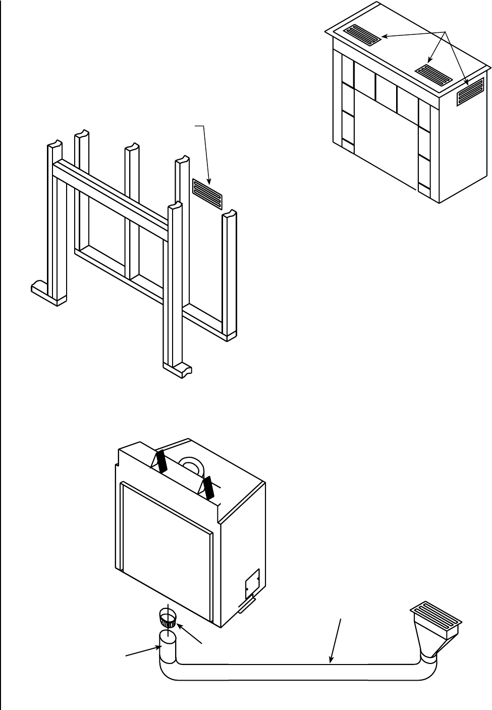
24
Increasing Efficiency and Hot Air Movement
A number of different options are available to the homeowner to maximize
the heat output and air movement to different rooms in the house.
Grills: If your Ravelle™ 42 gas fireplace is installed in a cabinet or a chase,
heat can be drawn from these enclosures and circulated into the living
area by cutting one or two openings covered by a register or Grill.
Whole Home Comfort System: The Whole Home Comfort System is a
very inexpensive and efficient way to move air into and heat other areas
of the house. In the bottom of the Ravelle™ 42 gas fireplace are four inch
and Six inch (152 mm) diameter knock-out plates. Four inch (102 mm)
or six inch (152 mm) diameter return air ducting may be fastened to the
bottom of the fireplace, run into another room in the house and terminated
with a grill. When the fireplace is burning, with or without the fireplace
fan running, air is drawn from a distant room (lowering the pressure in
that room) through the return air duct into the bottom of the fireplace.
The air then passes through the outer shell and heat exchanger of the
fireplace and into the room in which the fireplace is located. The hot air
in the fireplace room moves through an open doorway or hall into the
low pressure room from which the air was drawn. This system functions
well by convection even without the use of the fireplace fan. Six inch (152
mm) diameter ducting moves more air than four inch diameter ducting.
Ducting in uninsulated areas of a house (for example in the crawl space)
should be wrapped in insulation to ensure maximum heat retention. Check
local building codes - some areas may require firestops when the duct
passes from room to room.
Figure 33
Figure 34
Figure 35
Opening and Grill into
Adjoining Room
Possible Opening
and Grill Locations
on Cabinet
Note: Grill can be in the Wall, Ceiling, or Floor.
Up to 100 Feet (30.5M)
Maximum Run
Starter Ring
4” (102mm) or
6” (152mm)Duct
NOTE: DIAGRAMS & ILLUSTRATIONS ARE NOT TO SCALE.
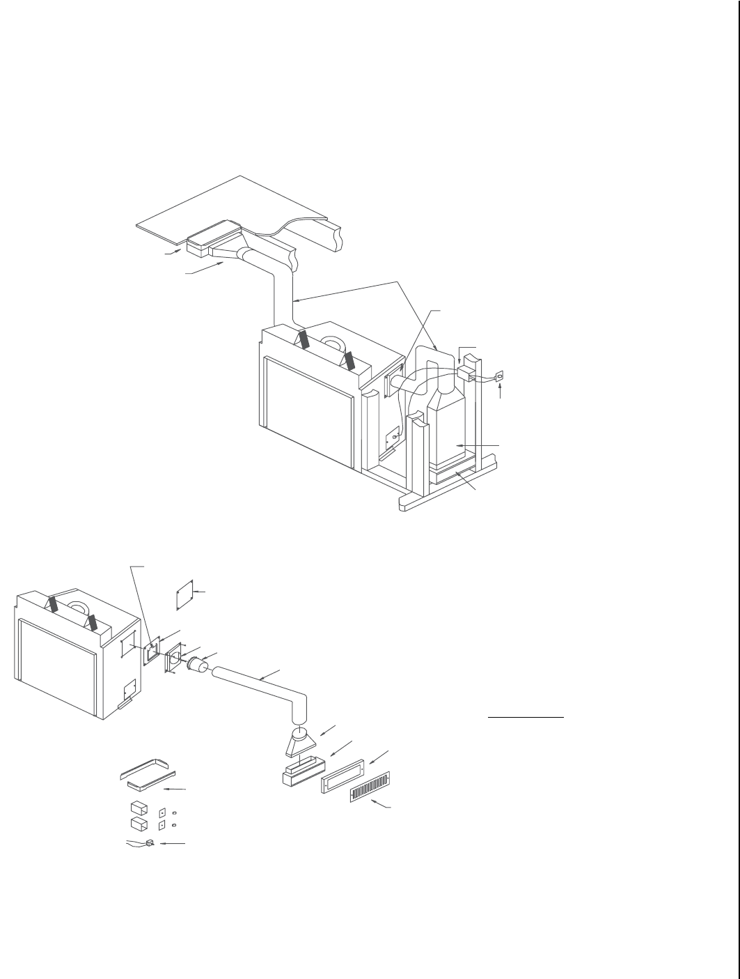
25
NOTE: DIAGRAMS & ILLUSTRATIONS ARE NOT TO SCALE.
Forced Air Heating Installation
Hot air can be drawn off the Ravelle™ 42 gas fireplace and moved into
other rooms of the house with the forced air heating system. This system
can be purchased as an option from your Lennox Hearth Products dealer
(part #75134).
System Overview
Fan Box
Duct Adapter (6" round to
10" x 31/4" Rectangular) Six Inch Duct (20' maximum length)
Switch Box
Fan Speed Control
Wall Stack Duct (10" x 31/4") for use
in areas of restricted clearance (Not
included as part of the kit--- available
at major hardware stores).
Fan Box
Forced Air Kit Components
Two Switch Boxes, Two Covers and Two Speed Control Knobs
Floor Mount
Adapters
Speed Control
Grille
Spacer
Fan Box
Duct Adapter
Six Inch Flex Duct
Starter Ring
Starter Ring Adapter
Cover Plate
Flapper Plate
Flapper
Fireplace Side Adapter
Additional Parts:
Two Angled Mounting Brackets
Two White---Headed Grille Screws
Six Wire Nuts
Sixteen Sheet Metal Screws
One Wire Clamp
The system draws heated air from the Ravelle 42 gas fireplace and moves
it with the use of a 150 CFM fan through six inch ducts into other rooms
in the house. The system acts as a forced air furnace. One or two systems
can be used with each Ravelle 42 gas fireplace.
Figure 37
Figure 36
SYSTEM OVERVIEW
Blower Box
Duct Adapter (6” round to
10” x 3-1/4” rectangular) Six Inch Duct (20 ft. maximum length)
Fireplace Side Adapter
Switch Box
Blower Speed Control
Blower Box
Wall Stack Duct (10” x 3-1/4”) for use in
areas of restricted clearance (not included
as part of the kit - available at major
hardware stores)
FORCED AIR KIT COMPONENTS
Flapper
Cover Plate
Flapper Plate
Starter Ring Adapter
Starter Ring
Six Inch Flex Duct
Duct Adapter
Blower Box
Spacer
Grill
Additional Parts:
Two Angled Mounting Brackets
Two White - Headed Grill Screws
Six Wire Nuts
Sixteen Sheet Metal Screws
One Wire Clamp
Two Switch Boxes, Two Covers and Two Speed Control Knobs
Floor Mount
Adapters
Speed Control
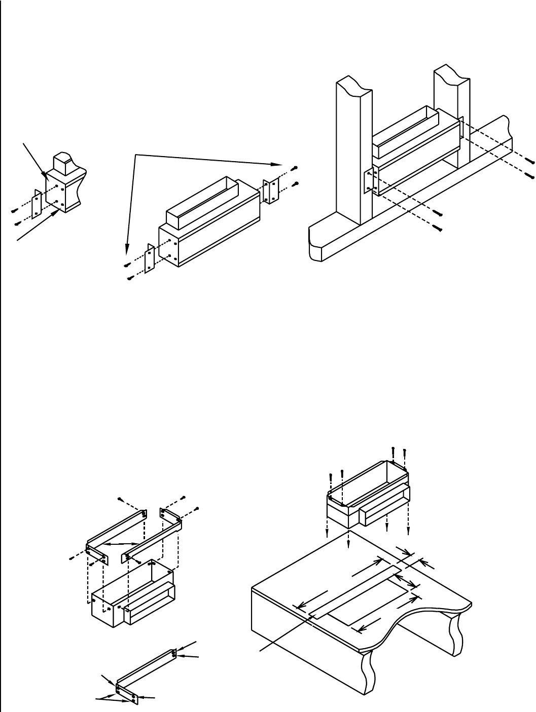
26 NOTE: DIAGRAMS & ILLUSTRATIONS ARE NOT TO SCALE.
The fan box may be located in the wall, floor, or ceiling.
Ceiling and Wall Mounting:
1) Fasten the two angled brackets to the side of the face box with the screws provided (see A below).
Floor Mounting:
1. Fasten the two floor mount adapters (B below) to the side of the fan box with the screws provided. The floor mount adapters have two sets of holes.
The upper holes (C below) should be used if the flooring material is thin and the lower holes (D below) should be used if the flooring material is
thick.
2. Cut the hole (E below) for the fan box. Since the fan box body is wider than the portion that comes up through the floor an additional piece of floor-
ing (F below) should also be cut out for the fan box to slide through. (Save this piece F and nail it back in place after the fan box is installed).
3. Slide the fan box through the cut holes and nail or screw it to the floor.
3. Then fasten the fan box to the
ceiling rafters or wall studs.
A
2. Fasten the bracket in
these holes for 2 x 4 walls.
Fasten the bracket in
these holes for 2 x 6 or
greater walls or ceiling.
B
14”
C
C
D
DF
E
2”
16” 5”
C
Figure 38
Figure 39
2) Fasten the bracket in these
holes for 2 x 4 walls.
3) Then fasten the blower box to the
ceiling rafters or wall studs.
Fasten the bracket in
these holes for 2 x 6 or
greater walls or ceiling.
16”
14”
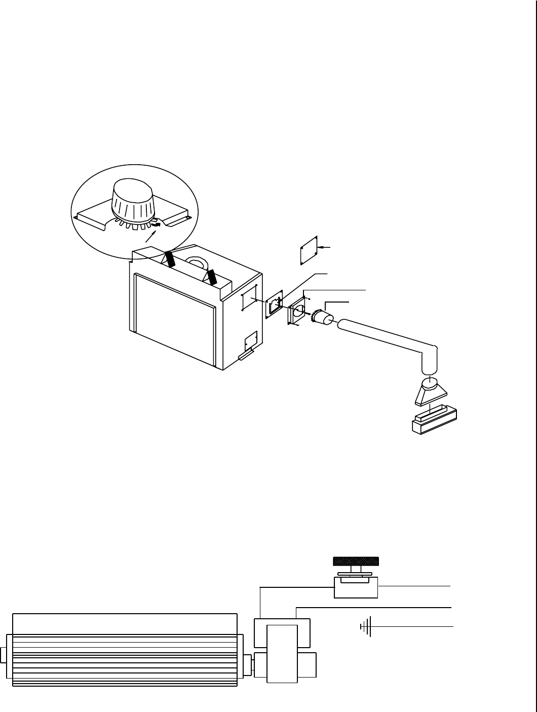
27
NOTE: DIAGRAMS & ILLUSTRATIONS ARE NOT TO SCALE.
Expanded View
Bend Tabs Under
Cover Plate
Flapper Plate
Starter Ring
Starter Ring Adapter
Duct Assembly:
The duct has zero clearance to combustibles.
1. Remove the cover plate from the top of the fireplace. Save the screws and discard the plate.
2. Insert the starter ring into the starter ring adapter and bend the tabs under to secure the ring to the adapter. See the expanded view below.
3. Place the adapter with the attached starter ring over the flapper plate and secure them to the top of the fireplace using the four screws that held
the cover plate.
4. Fasten the remaining components of the duct: flex line, duct adapter, wall stack and fan box using at least three sheet metal screws and aluminum
duct tape at each joint.
5. Secure the ducting to prevent sagging.
Wiring of the Forced Air System:
Disconnect the electrical supply to the fireplace at the electrical panel prior to wiring the forced air system fan. All wiring should be done by a quali-
fied electrician.
1. After installing the fan box and ducting from the fireplace to the fan box, the wiring of the fan box should be undertaken. Included in the ducting kit
are two electrical switch boxes. One is for installation in new construction and the other is to be used in a remodel. Select the switch box needed
and fasten it to the wall framing in the room in which the fan box is located.
(Instructions continue on the following page).
Green (Ground)
Black (Hot)
White (Neutral)
Speed Control
Blower
From
Power
Source
Figure 40
Figure 41
Supply Leads
from Fireplace
Speed Control
Black (Hot)
White (Neutral)
Green (Ground)
Cover Plate
Flapper Plate
Starter Ring Adapter
Starter Ring
Bend Tabs Under
Expanded View
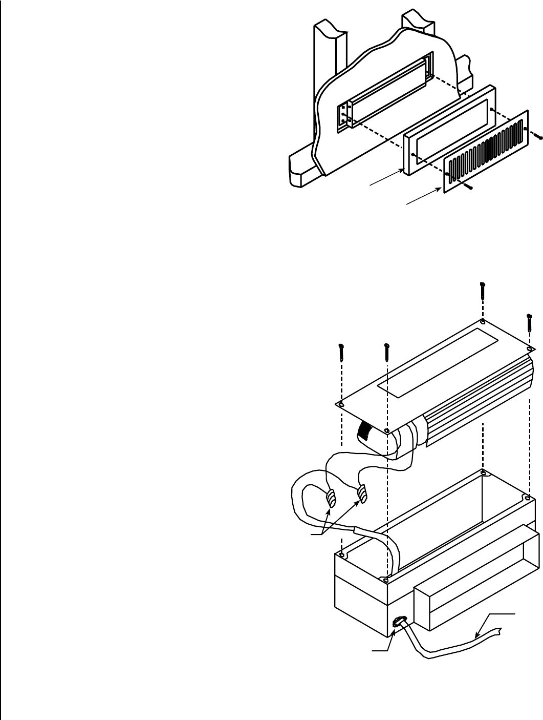
28 NOTE: DIAGRAMS & ILLUSTRATIONS ARE NOT TO SCALE.
Wiring of the Forced Air System Continued:
2. Remove the cover over the electrical box at the right lower rear of the
fireplace. Run sheathed wire from the fireplace electrical box to the
switch box and from the switch box to the fan box. Install the wire
clamp in the unused knock-out hole in the fireplace electrical box
cover. Run the end of the sheathed wire through this wire clamp. In the
electrical box are a white wire and a red wire with clear caps on their
ends. Remove these caps and join the red wire and black wire with
the wire nuts provided. Also join the white wire from the fireplace with
the white wire from the sheathed wire using the wire nuts provided.
Fasten the ground wire from the sheathed wire to the green grounding
screw in the electrical box. When the fireplace gets up to temperature,
a heat activated switch will close and allow electricity to flow to the
red wire.
3. At the switch box, cut the black sheathed wire, strip back the insula-
tion and join each end (with the wire nuts provided) to a lead from the
speed control. It does not matter which lead from the speed control is
fastened to which black wire. After making these connections, roll the
connectors and wire into the switch box. Two different colors of covers
and knobs come with the kit. Select the cover desired and fasten the
speed control and cover to the box with the screws supplied. Push
the desired knob onto the shaft of the speed control.
4. Remove the four screws holding the fan to the fan box and lift fan out
of the fan box (see Figure 43). Feed the sheathed wire A through the
wire clamp B. Remove the insulation from the sheathed wire and the
two wires coming from the fan motor. Join together using the wire
nuts provided the black wire from the motor and the black sheathed
wire. Also join the two white wires. Fasten the ground wire to the green
grounding screw inside the fan box. Reinstall the fan in the fan box
using the four screws.
Notes:
The speed of this forced air system fan can be controlled by the speed
control that is installed with it. The speed control also has an off position.
This fan is energized only when the fireplace is up to temperature. It will
also shut off automatically when the fireplace cools down.
To maximize hot air distribution, this forced air system can be used in
conjunction with the Whole Home Comfort System described in this
manual.
Grill Installation: The Grill that covers the fan box is secured with the
two white-headed screws provided. When the fan box is mounted in a 2”x
4” framed wall the box will extend past the sheetrocked wall into the room.
In these installations the Grill spacer should be used (see Figure 42).
Figure 42
Figure 43
Grill Spacer
Grill
C
B
A
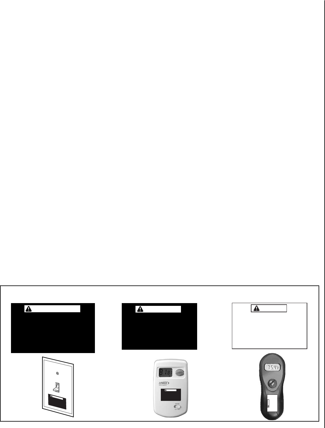
29
NOTE: DIAGRAMS & ILLUSTRATIONS ARE NOT TO SCALE.
La chimenea caliente cau-
sará quemaduras graves
Nunca permita que los niños
toquen el vidrio ni otras
partes de la chimenea
ADVERTENCIA
Un foyer chaud peut causer
de graves brûlures
Ne laissez jamais un enfant
toucher à la vitre ou à toutes
autres parties du foyer
AVERTISSEMENT
ATTACHING SAFETY IN OPERATION WARN-
INGS
It is required that the safety instruction labels fur-
nished with the fireplace be affixed to the operation
and control point of the fireplace. A safety instruction
label must be affixed to the wall switch plate where
the fireplace is turned on and off (See Figure A)
or wall thermostat (See Figure B) and if used on
the remote control handheld transmitter (Figure
C). To properly complete the installation of this
fireplace, locate the multi-lingual adhesive labels
provided with the Care and Operation Instructions
and proceed as follows:
1. Locate the wall switch or wall thermostat that
controls the fireplace (verify the switch operates
the fireplace by turning it on and off). Clean the
wall switch plate or wall thermostat thoroughly
to remove any dust and oils. Affix the label to
the surface of the plate of the wall switch that
controls the fireplace (Figure A) or the wall
thermostat (Figure B). Choose the language
primarily spoken in the home. If unknown, affix
the English language label.
2. If a remote control is used to control the fireplace,
locate the transmitter and clean it thoroughly
to remove any dust and oils. Affix the label to
the surface of handheld transmitter (Figure C).
Choose the language primarily spoken in the
home. If unknown, affix the English language
label.
3. If you are unable to locate the labels, please call
Lennox Hearth Products or your nearest Lennox
Hearth Products dealer to receive additional
safety instruction labels free of charge.
Cat. No. H8024 Replacement Label Kit
LENNOX HEARTH PRODUCTS
1-800-9-LENNOX
Note: English is red text on clear label. French and
Spanish are white text on black label.
Hot Fireplace Will Cause
Severe Burns
Never Allow Children to
Touch Glass or other Fire-
place Parts
WARNING
La chimenea caliente
causará quemaduras graves
Nunca permita que los niños
toquen el vidrio ni otras
partes de la chimenea
Un foyer chaud peut causer
de graves brûlures
Ne laissez jamais un enfant
toucher à la vitre ou à toutes
autres parties du foyer
ADVERTENCIA
Figure A
INSTALLER INSTRUCTIONS - ATTACHING SAFETY IN OPERATION WARNINGS
It is the installers responsibility to ensure these warnings are properly affixed during installation. These warning labels are a
critical step in informing consumers of safe operation of this appliance.
Hot Fireplace Will Cause
Severe Burns
Never Allow Children to
Touch Glass or other Fire-
place Parts
WARNING
Figure B Figure C
DIAGRAMMES DES ÉTIQUETTES DE SÉCURITÉ / DIAGRAMAS DE ETIQUETAS DE SEGURIDAD / SAFETY LABEL DIAGRAMS
APPOSITION DES MISES EN GARDE RELATIVES
À LA SÉCURITÉ D’UTILISATION
Il est impératif que les étiquettes de sécurité fournies
avec le foyer soient collées à côté des dispositifs
de contrôle du foyer. Une étiquette de sécurité doit
être collée sur la plaque de l’interrupteur contrôlant
l’allumage du foyer (voir Figure A) ou sur le thermostat
mural (voir Figure B) et, le cas échéant, sur le boîtier
de la télécommande (Figure C). Pour achever l’instal-
lation correcte de ce foyer, procédez comme suit avec
les étiquettes adhésives en langues étrangères fournies
avec les instructions d’utilisation et d’entretien :
1. Repérez l’interrupteur ou le thermostat mural qui
contrôle le foyer (vérifiez que l’interrupteur
contrôle le fonctionnement du foyer en le faisant
basculer de Marche à Arrêt, et vice-versa). Nettoyez
soigneusement la plaque murale de l’interrupteur
ou le thermostat mural pour éliminer la poussière
et les traces de graisse ou d’huile. Collez l’étiquette
sur la surface de la plaque de l’interrupteur mural
qui contrôle le foyer (Figure A) ou du thermostat
mural (Figure B). Choisissez la langue qui est
principalement parlée dans la résidence du
propriétaire. En cas de doute, collez l’étiquette en
anglais.
2. Si une télécommande est utilisée pour contrôler
le foyer, nettoyez la soigneusement pour éliminer
la poussière et les traces de graisse ou d’huile.
Collez l’étiquette sur le boîtier de la télé-
commande (Figure C). Choisissez la langue qui est
principalement parlée dans la résidence du proprié-
taire. En cas de doute, collez l’étiquette en anglais.
3. Si vous ne trouvez pas les étiquettes, veuillez
appeler Lennox Hearth Products ou votre distribu-
teur Lennox Hearth Products local pour recevoir
gratuitement des étiquettes supplémentaires.
Étiquettes de remplacement, n° cat. H8024
LENNOX HEARTH PRODUCTS
1-800-9-LENNOX
Remarque : Le texte anglais est rouge sur un support
transparent. Le texte français et espagnol est blanc
sur un support noir.
COLOCACIóN DE ADVERTENCIAS DE SEGURIDAD
EN OPERACIóN
Se requiere que las etiquetas de instrucciones de
seguridad incluidas con la chimenea se coloquen en
el punto de operación y control de la misma. Se debe
colocar una etiqueta de instrucciones de seguridad
en la placa del interruptor de pared desde el cual se
enciende y se apaga la chimenea (ver la Figura A) o en el
termostato de pared (ver la Figura B) y en el transmisor
de control remoto (Figura C) si se usa. Para completar
correctamente la instalación de esta chimenea,
encuentre las etiquetas adhesivas multilingües incluidas
con las instrucciones de cuidado y operación y haga
lo siguiente:
1. Identifique el interruptor o el termostato de pared
que controla la chimenea (verifique que el interruptor
opera la chimenea encendiéndola y apagándola).
Limpie bien la placa del interruptor o el termostato
de pared para quitar el polvo y aceite. Pegue la
etiqueta en la superficie de la placa del interruptor que
controla la chimenea (Figura A) o en el termostato
de pared (Figura B). Seleccione el idioma que
más se habla en la casa. Si no sabe cuál es, use la
etiqueta en inglés.
2. Si se usa un control remoto para controlar la
chimenea, encuentre el transmisor y límpielo bien
para quitar el polvo y aceite. Pegue la etiqueta en
la superficie del transmisor (Figura C). Seleccione
el idioma que más se habla en la casa. Si no sabe
cuál es, use la etiqueta en inglés.
3. Si no puede encontrar las etiquetas, sírvase llamar
a Lennox Hearth Products o al distribuidor de
Lennox Hearth Products más cercano para recibir
etiquetas de instrucciones de seguridad adicionales
gratuitas.
Juego de etiquetas de repuesto - Nº de cat. H8024
LENNOX HEARTH PRODUCTS
1-800-9-LENNOX
Nota: La etiqueta en inglés es transparente con texto
rojo. Las etiquetas en francés y español son negras
con texto blanco.
AVERTISSEMENT

30
Operating Instructions
Pre-Lighting Checklist
Be sure to check these items before the initial lighting of the
fireplace:
cThe fireplace gas label corresponds to the gas supply available
- that is "natural gas" for natural gas or "LP gas" for Propane
gas.
cGas pressure has been checked carefully - see Page 23.
cAll gas fittings have been checked for leaks.
cAll clearances to combustibles have been met - see Page 7.
cAll combustible materials have been removed from the area in
front of the fireplace.
cAll vented areas of the fireplace face are unobstructed.
cHouse is ventilated to clear initial paint curing odors - see Page
32.
cAll packaging materials have been removed from the firebox.
cWhile fireplace is cool, fingerprints or other marks have been
cleaned from any gold or nickel surfaces with denatured alcohol
and a soft cloth. Marks left on these surfaces may become etched
into the finish if not removed prior to burning the unit.
cBrick panel, log set, volcanic stone and embers have been
installed.
cThe glass door is in place and is properly sealed.
Lighting Instructions
The following is a copy of the operating and lighting instructions
found with each fireplace:
FOR YOUR SAFETY READ BEFORE OPERATING
WARNING: IF YOU DO NOT FOLLOW THESE INSTRUCTIONS
EXACTLY, A FIRE OR EXPLOSION MAY RESULT CAUSING PROP-
ERTY DAMAGE, INJURY, OR LOSS OF LIFE.
CAUTION: HOT WHILE IN OPERATION. DO NOT TOUCH. KEEP
CHILDREN, FURNITURE, GASOLINE AND OTHER LIQUIDS WITH
FLAMMABLE VAPORS AWAY. NEVER OPERATE UNIT WITH GLASS
OFF OR ATTEMPT TO REMOVE THE GLASS WHILE HOT.
A. This appliance is equipped with a piezo ignition device to light
the pilot. When lighting the pilot, follow these instructions
exactly.
B. BEFORE LIGHTING, smell around the appliance area for gas.
Be sure to smell next to the floor, because some gas is heavier
than air and will settle on the floor.
WHAT TO DO IF YOU SMELL GAS:
DO NOT try to light the appliance.
DO NOT touch any electric switch,
DO NOT use any phone in the building. Immediately call your
gas supplier from a neighbor's phone. Follow the gas supplier's
instructions. If you cannot reach your gas supplier, call the fire
department.
C. Use only your hand to push in or turn the gas control knob.
Never use any tool. If the knob will not push in or turn by hand,
don't try to repair it, call a qualified service technician. Force or
attempted repair may result in a fire or explosion.
D. DO NOT use this appliance if any part has been under water.
Immediately call a qualified service technician to inspect the
appliance and to replace any part of the control system and any
gas control which has been under water.
OPERATING INSTRUCTIONS
CAUTION: YOUR Lennox Hearth Products gas FIREPLACE MUST
ALWAYS BE OPERATED WITH GLASS IN PLACE.
STOP!! Read the safety information above before proceeding.
1. Open the lower door. Make sure gas supply shut-off cocks are
open and ON/OFF rocker switch is "OFF." If equipped with a
thermostat, set it to the lowest setting.
2. Turn off all electrical power to the appliance.
3. Push in gas cock dial slightly and turn clockwise to
"OFF."
Note: Dial cannot be turned from "PILOT" to "OFF" unless dial
is pushed in slightly. Do not force.
4. Wait five minutes to clear out any gas. Then smell for gas,
including near the floor. If you smell gas, STOP! Follow "B"
above. If you don't smell gas continue.
5. Locate the pilot by looking at the left center of the burner,
under the left elevated log. Blue flame will be seen when the
pilot is lit.
6. Turn the gas control knob counter-clockwise to the
"PILOT" position.
7. Push the knob all the way in and hold in that position. Im-
mediately light the pilot by pressing the igniter button several
times until pilot is lit. Continue to hold the knob in for about
30 seconds after the pilot is lit. Release knob and it will pop
back out. Pilot should remain lit. If it goes out, repeat steps
4-8 holding knob in an additional 15 seconds after pilot is lit.
If knob does not pop out when released, stop and immediately
call your service technician or gas supplier. If the pilot will not
stay lit after several tries, turn the gas control knob to "OFF" and
call your service technician or your gas supplier.
8. After pilot is lit, turn gas control knob counter-clockwise
to "ON." Knob can only be turned to "ON" if the knob
has popped out.
9. To turn burner on, turn "ON/OFF" rocker switch to "ON" or
set the thermostat to the desired temperature above room
temperature.
10. Adjust the flame height (and heat output) by turning the flame
height knob clockwise for full flame and counter-
clockwise for reduced flame.
11. Turn on the electric power to the appliance and set the blower
to the desired air flow after it turns on when the appliance
reaches operating temperature.
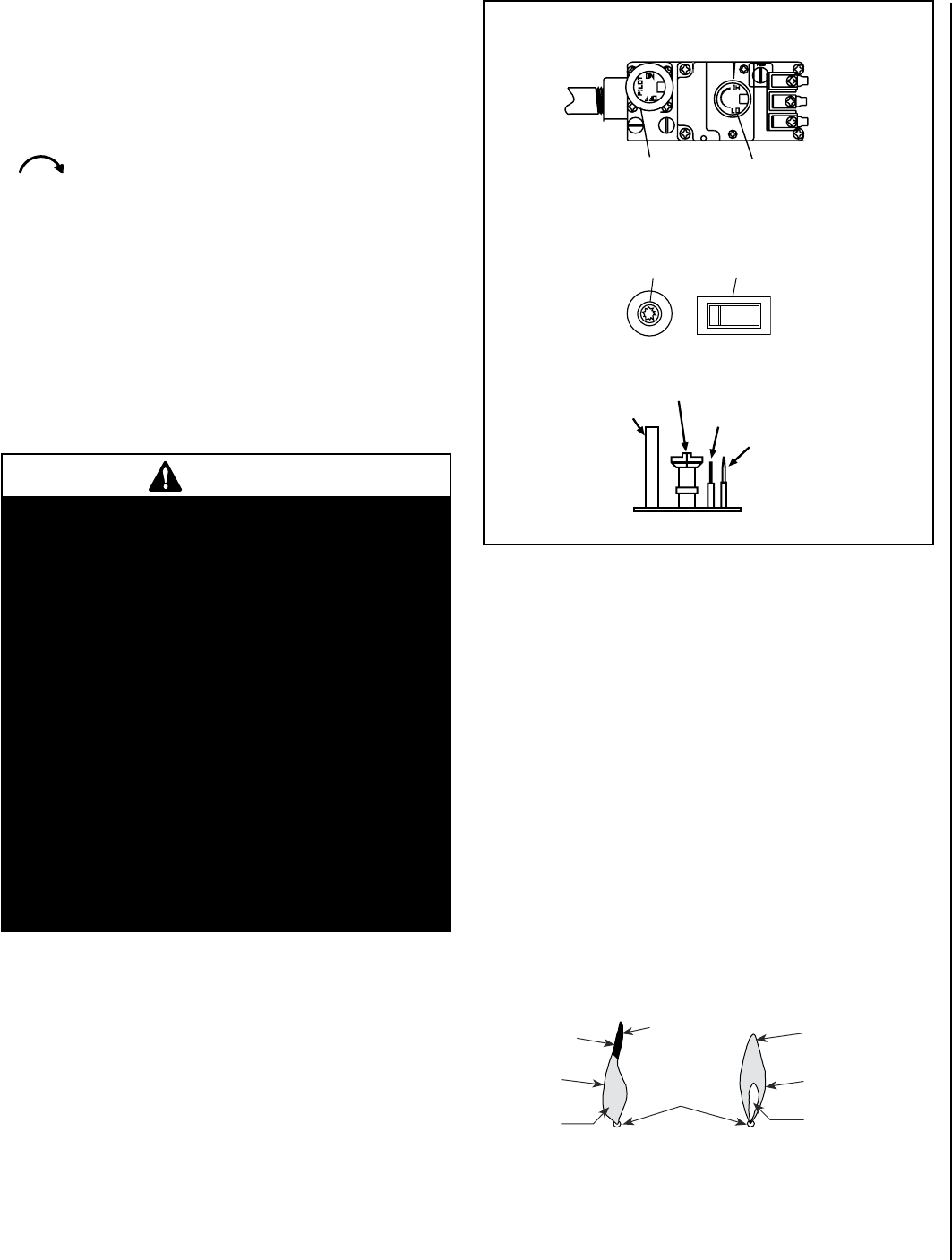
31
TO TURN OFF GAS TO APPLIANCE
1. Turn off the "ON/OFF" rocker switch and/or thermostat (if
installed) to its lowest setting.
2. Turn off electric power to the appliance if service is to be
performed.
3. Push in gas control knob slightly and turn clockwise
to "OFF." Do not force.
This appliance needs fresh air for safe operation and must be
installed so there are provisions for adequate combustion and
ventilation air.
SHUTDOWN PROCEDURE
To turn off the burner, turn the rocker switch to "OFF" or adjust
the thermostat (if installed) to a setting below room temperature.
The pilot will remain lit for future burner ignition. For complete
shutdown, see "TO TURN OFF GAS TO APPLIANCE" above.
Flame Color and Behavior
Your Ravelle™ 42 gas fireplace is designed for maximum heating ef-
ficiency. Therefore, upon lighting of the main burner the flames will be
semi-transparent or “bluish.” After 10-20 minutes of operation the logs
will heat up and the flames will become a yellow/orange color.
Adjusting the fireplace to cause the flames to turn orange sooner may
result in poor combustion, sooting and a hazardous situation. See Figure
45 showing proper flame appearance.
When testing for proper operation - If an optional thermostat is installed
adjust it to its highest temperature setting. Visually determine that main
burner gas is burning properly: i.e., no floating, lifting or flashback.
Adjust the primary air shutter(s) as required. Check for proper main
burner operation at both high and low flame.
PILOT ASSEMBLY
Thermopile
Veilleuse à gaz Igniter (electrode)
Allumeur
Thermocouple
Gas Pilot Hood
TP/TH
TH
TP
Gas Control Knob
(Pilot / On / Off)
OFF
ON
Piezo Igniter
Allumeur ON/OFF Switch
Interrupteur
Flame Height Control
Knob (HI/LO)
No Blue Flame
Center
Soot at
Flame Tip
Dark Orange
Flame
IMPROPERLY
BURNING FLAME
Soot above
Flame Tip No Soot at
Flame Tip
PROPERLY
BURNING FLAME
Semi-Transparent
Yellow Flame
Blue Flame
Center
Ports on Burner
Assembly
Burner Flame Appearance
Figure 44
Figure 45
SIT Millivolt Gas Valve
WARNINGS
•
Improper installation, adjustment, alteration,
service or maintenance can cause injury or
property damage. For assistance or additional
information, consult a qualified installer, service
agency or your gas supplier.
•
Operation of this appliance when not connected
to a properly installed and maintained venting
system can result in carbon monoxide (CO)
poisoning and possible death.
•
Carbon monoxide poisoning – Early signs of
carbon monoxide poisoning resemble the flu
with headaches, dizziness, or nausea. If you
have these signs, get fresh air at once! Have
the heater inspected by a qualified service
technician. Some people are more affected by
carbon monoxide than others. These include
pregnant women, people with heart or lung
disease or anemia, those under the influence
of alcohol and those at high altitudes.

32 NOTE: DIAGRAMS & ILLUSTRATIONS ARE NOT TO SCALE.
Air Shutter Adjustment
The Ravelle™ 42 gas fireplace has an air shutter control lever located
at the upper left corner beneath the firebox (see Figure 46). The lever
is linked to the primary air shutter on the main burner. The air shutter
regulates the amount of primary air the burner receives and therefore
how clean the fireplace burns. The air shutter should only be adjusted by
a qualified gas technician. The fireplace should burn for about 15 minutes
with the logs installed before adjusting the air shutter. Moving the lever
to the left will open the shutter and turn the flames more transparent
and blue. Moving the lever to the right will close the shutter and turn the
flames more orange.
CAUTION: The air shutter should never be set so as to make the tips of
the flames sooty or create sooting on the viewing glass, logs, or heat
exchanger. If soot begins to form after burning, the air shutter should
be opened gradually until the sooting condition stops. Gas quality and
gas pressure may vary which can affect the burning characteristics of
the fireplace.
Figure 46
Quiet Operation
As the Ravelle 42 gas fireplace is burning a number of normal operational
sounds may be heard. The flow of gas through the gas valve and orifice
may make a rushing or whistling noise. If this noise is objectionable,
it can be reduced by turning down the flame. Turning down the flame
can reduce total heat output by more than 30%. When the blower turns
on, the sound of rushing air may be heard. The blower sounds may be
reduced by adjusting the speed control located behind the lower door.
Also, a slight clicking sound may be heard as the gas valve or blower
switch turn on and off.
Blower Operation
Your Ravelle 42 gas fireplace comes equipped with a 200 CFM blower
with a variable speed control and an automatic temperature activated
on/off snap switch.
Operation:
1. After the fireplace warms up, a heat activated switch will turn on the
fan. A fan speed control is located behind the lower door. The speed
control has an off position and the knob can be rotated to set the fan
at the desired speed. The fan will not operate until the fireplace is
warm.
2. Once the fan turns on, set the speed control knob to the desired
speed. No further adjustment is necessary, the fan will turn on and
off automatically whenever the fireplace is warm.
3. If you do not wish to have the fan on, turn the speed control knob
until it clicks to the “OFF” position.
Optional Wall Thermostat
If an optional wall thermostat is to be installed, install the thermostat per
the manufacturers instructions (provided with the thermostat). Failure
to follow manufacturers instructions could result in a malfunction. Pay
special attention to the thermostat location requirements. If the loca-
tion requirements are not adhered to the appliance, erratic operation or
failure may occur.
Do not mount the thermostat where it may be affected by:
• Radiant heat from this appliance, fireplaces, sun or other heat
sources.
• Drafts or dead spots behind doors or in corners.
• Hot or cold air from ducts.
Paint Curing
This fireplace has been painted with a high temperature metallic paint. It
leaves the factory dry to the touch, but completes the curing process as
the fireplace is used. To cure the paint, burn the appliance four successive
times for 10 minutes each time with a five minute cool down between
each firing. Also some parts of the appliance may be lightly coated with
machining oil. Ventilate the house during these first firings as the paint
and oil give off unpleasant odors. It is recommended that persons sensi-
tive to an imbalance in the indoor air quality avoid the fireplace during
the curing process.
Expanded View of Air
Shutter Control Lever
Open Close
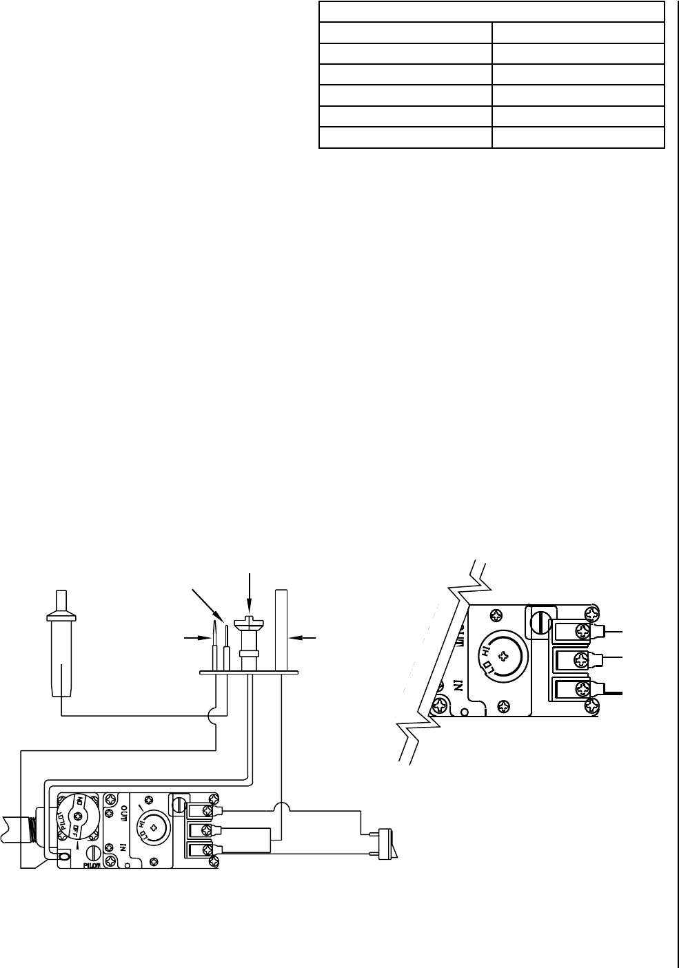
33
Operating Options
Your Ravelle™ 42 gas fireplace comes equipped with an “On/Off” rocker
switch used to turn the burner on and off while the pilot light is on. The
switch is a round rocker switch located behind the lower door of the
fireplace’s face.
A wall-mounted switch, a millivolt wall thermostat, or a remote control
can be used to supplement the rocker switch. The gas valve is powered
by millivolts generated by the pilot assembly. This millivolt system is
very sensitive to electrical resistance, therefore make sure all connec-
tions are tight, clean and free from corrosion. Do not splice any millivolt
wires. Consult the table on this page to determine the proper gage of
wire for the thermostat or wall switch connections. This table refers to
the total length of the wire (out to the switch and back). The thermostat
must be a millivolt type. A 24-volt furnace thermostat will not work.
Never hook up household current - 120 Volts - to the millivolt system.
It is not recommended to hook up any more than two switches to the
fireplace (for example a rocker switch and a wall thermostat). Additional
switches may affect the system resistance and increase the chance of
the burner not igniting.
Follow the instructions included with the thermostat or remote control
for wiring. The thermostat, remote control and rocker switch will turn the
burner on and off independently. Be sure to set the rocker switch to the
“Off” position when using the thermostat or remote control and set the
thermostat or remote control to the lowest temperature when you wish
to use the rocker switch only, otherwise one may override the other.
Thermostat Wire
Wire Size Maximum Length
12 Gage 100 Feet
14 Gage 64 Feet
16 Gage 40 Feet
18 Gage 25 Feet
20 Gage 16 Feet
Millivolt Control System
This fireplace operates on a millivolt control system. As such, no addi-
tional power supply is needed for the fireplace to heat. The pilot assembly
contains a thermocouple, that when heated by the pilot flame, generates
electricity (millivolts- mV=1/1000 of a volt) which opens a valve allow-
ing gas to flow to the pilot assembly. The pilot assembly also contains a
thermopile, that when heated by the pilot flame, generates electricity that
flows to terminal #1 (labeled THTP) on the gas valve. When the electricity
is conducted from terminal #1 through the on/off switch, thermostat,
or receiver of the remote control to terminal #3 (labeled TH) on the gas
valve, the main burner will ignite.
CAUTION: Label all wires prior to disconnection when servic-
ing controls. Wiring errors can cause improper and dangerous
operation.
ATTENTION: Au moment de l'entretien des commandes,
étiquetez tous les fils avant de les débrancher. Des erreurs
de cáblage peuvent entraîner un fonctionnement inadéquat et
dangereux.
Figure 47
NOTE: DIAGRAMS & ILLUSTRATIONS ARE NOT TO SCALE.
Millivolt Control Schematic
Sparker
Pilot Hood
ON/OFF Rocker Switch, Thermo-
stat, or Remote Thermostat
Pilot Assembly
Thermocouple
Piezo Igniter
White
Gas Inlet
Pilot Gas Line
Thermopile
Brown
Wiring Terminals
TH
TP
TH/TP
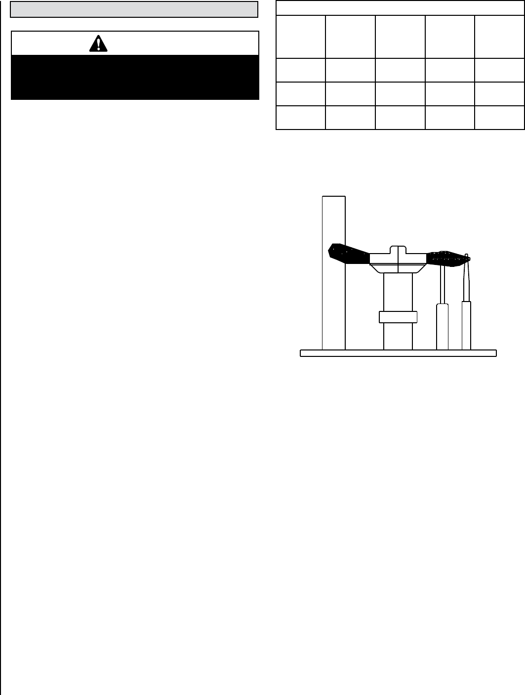
34 NOTE: DIAGRAMS & ILLUSTRATIONS ARE NOT TO SCALE.
Vent Pipe Maintenance
Conduct an inspection of the venting system semi-annually. Recom-
mended areas to inspect are as follows:
1. Check areas of the venting system which are exposed to the elements
for corrosion. These will appear as rust spots, streaks, or in extreme
cases, holes. These components should be replaced immediately.
2. Remove the cap and shine a flashlight down the vent. Remove any
bird nests or other foreign material.
3. Check for evidence of excessive condensate, such as water droplets
forming in the inner liner and subsequently dripping out at joints.
Continuous condensate can cause corrosion of caps, pipe and fittings.
It may be caused by having excessive lateral runs, too many elbows,
or exterior portions of the system being exposed to cold weather.
4. Inspect joints to verify that no pipe sections or fittings have been dis-
turbed and consequently loosened. Also check mechanical supports
such as wall straps or plumbers’ tape for rigidity.
CAUTION: Wear gloves and safety glasses for protection while
doing required maintenance.
Verify proper operation after servicing.
S'assurer que l'appareil fonctionne adéquatement une fois
l'entretien terminé.
Maintenance Checklist
The following should only be performed by a qualified service techni-
cian.
1. Annual inspection should be made and the following checks per-
formed:
oWhen unit is cool, glass viewing door and inspect burner for dirt, soot
and lint accumulations and remove if necessary. If excessive soot ac-
cumulation is present on burner, have a qualified service technician
adjust the burner for proper combustion.
oClean inside of glass with gas fireplace glass cleaner. NEVER attempt
to remove or clean the glass when the unit is hot.
oCheck the hot air outlet vents for lint or other accumulations. Never
block or restrict vent openings, obstruct flow of ventilation air, or use
vents other than those approved for use with this appliance.
oCheck that direct-vent pipe, air intake and flue are open and free of
soot, blockage, or debris.
oCheck gaskets once a year. Gaskets must be tight. Replace if neces-
sary.
oInspect the pilot system for proper flame. NEVER ADJUST THE PILOT
until after the gas pressure has been checked and supply lines have
been completely bled (this may take an hour or more when bleeding
through the pilot). All pilots are checked and burned at the factory prior
to shipment. The pilot adjustment screw is located to the upper right
of the flame height control knob. Adjust the pilot screw to properly
size the flames. Flames should completely surround the thermopile
and thermocouple and extend across the main burner tube ports. Be
careful not to back the screw out of its threads. Check for gas leaks
using a gas leak test solution.
oCheck that the area around the fireplace is kept clear and is free of
combustible materials, gasoline and other flammable vapors and
liquids.
oCheck the millivolt system as per the table on this page.
2. The viewing glass should be cleaned periodically (see Glass Main-
tenance).
3. Should repairs or maintenance of the fireplace require the disas-
sembly of the vent/air intake system, the reassembly and resealing
should be completed by a qualified service technician and follow
the instructions on Page 17 of this manual.
Millivolt and System Checks
Check
Test
To
Test
Connect
Meter
Leads to
Terminals
Thermostat
Connects
Meter Read-
ing
Should Be
A Complete
System
2 & 3 Closed 100 MV
or More
B Thermopile
Output
1 & 2 Open Greater Than
325 MV
C System
Resistance
2 & 3 Closed 2.5 Ohms
Proper Pilot Flame Appearance
Figure 48
MAINTENANCE AND SERVICING
WARNING
Turn off gas and electrical power to the fireplace
and allow it to cool before cleaning or servicing
the appliance.
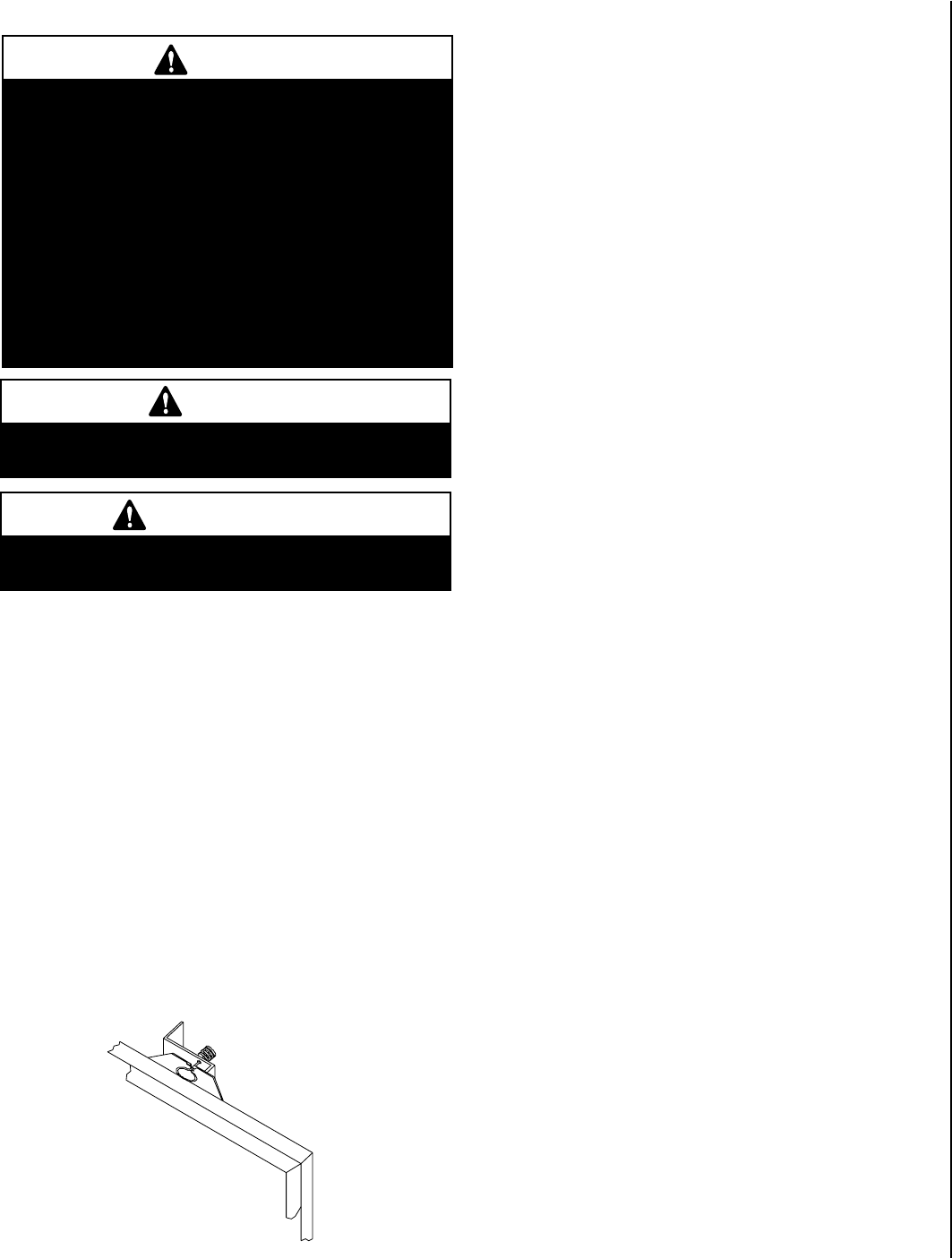
35
NOTE: DIAGRAMS & ILLUSTRATIONS ARE NOT TO SCALE.
Glass/Door Maintenance
Cleaning: When cool, the glass may be cleaned with a clean, soft cloth
and a household glass cleaner. For cleaning white condensation from
the interior glass use a gas fireplace glass cleaner available from your
fireplace dealer. Use of caustic or abrasive cleaners may damage glass.
Gold or nickel plated doors must be cleaned with a household glass
cleaner or denatured alcohol and a soft cloth before firing or fingerprints
and stains will remain permanently. DO NOT spray commercial glass
cleaner with ammonia on the door and glass gasket as it may dissolve
the gasket glue.
Repair: If the glass is broken in the glass door, the entire door (metal
frame, gasket and glass) should be replaced as a unit. This replacement
glass door is available from your Lennox Hearth Products dealer. Do not
use substitute parts or materials. The glass is neo-ceramic and alterna-
tive types must not be used.
NOTE: BE CAREFUL NOT TO SPRAY COMMERCIAL GLASS
CLEANER WITH AMMONIA ON GASKET AREA OF DOOR. AM-
MONIA WILL DISSOLVE GASKET GLUE.
NOTE: GOLD PLATED SURFACE MUST BE CLEANED WITH GLASS
CLEANER AND SOFT RAG BEFORE FIRING THE FIRST TIME OR
FINGER PRINTS AND STAINS WILL REMAIN PERMANENTLY.
NEVER USE BRASS POLISH TO CLEAN GOLD, THIS WILL RE-
MOVE GOLD PLATING!
Fuel Conversion
Converting the Ravelle™ 42 gas fireplace between natural gas and LP can
be accomplished by either changing the cassette (valve and pilot assembly)
or installing a conversion kit (regulator, burner orifice and changing the
orifice position on the pilot). Only a qualified service technician should
perform the conversion.
Cassette Removal:
1. Be sure the gas supply is shut off and the fireplace electrical supply
is shut off at the electrical panel before beginning the conversion.
Disconnect the gas supply from the fireplace, being careful not to
apply pressure to the valve in the process.
2. Remove the log set and brick panels (see Brick Panel and Log Set
Installation).
3. Remove the two allen head screws at the left and right rear of the
firebox securing the burner support. Lift out the burner and burner
support.
4. Remove the two allen head screws holding the burner in place.
5. Remove the labeled cover through which the valve control knobs
protrude by removing the two allen head screws securing it and slide
it off the valve knobs.
6. Mark and disconnect wires on valve terminals #1 and #3 connected
to the burner on/off switch, thermostat, or remote control.
7. Remove all the allen head screws (around the perimeter of the cassette
panel) fastening the cassette to the firebox.
8. Grasp the cassette assembly from inside the firebox and pull it into
the firebox and out of the fireplace.
9. Install new, converted, or serviced cassette in the reverse order of
removal. Replace gasket if necessary.
10. All parts and wires must be correctly reinstalled to ensure safe and
proper operation of the unit.
Conversion Kit:
Please see instructions provided with conversion kit.
Figure 49
Door Latch
Glass Door
Only doors certified with the appliance shall be used.
Seules des portes certifiées pour cet appareil doivent être
utilisées.
CAUTION: DO NOT abuse glass door by striking or slamming
shut.
Do not remove glass door while the appliance is hot.
WARNING
• Do not attempt to substitute the materials used
on these doors, or replace cracked or broken
glass.
• Handle this glass with extreme care! Glass is
susceptible to damage – Do not scratch or handle
roughly while reinstalling the glass door frame.
• The glass door(s) of this appliance must only be
replaced as a complete unit as provided by the
manufacturer. Do not attempt to replace broken,
cracked or chipped glass separately.
• Do not attempt to touch the front enclosure glass
with your hands while the appliance is in use.
WARNING
Do not operate appliance with the glass front
removed, cracked or broken.
AVERTISSEMENT
Ne pas utiliser l'appareil si le panneau frontal en
verre n'est pas en place, est craqué ou brisé.
Opening and Removing Door
While holding the door against the firebox, pull each latch forward and up
- releasing the top of the glass door. To remove the door, grasp it firmly
with both hands and lift it up so the two tabs at the bottom of the door
are lifted out of their retaining slots. The glass door is quite heavy, so it
is important to place it in a secure spot until reinstalled. To reinstall the
door, the tabs at the bottom of the door must be inserted in the slots
at the bottom of the firebox. The spring loaded latches must be pulled
forward and down to apply pressure against the door.

36
SYMPTOM PROBABLE CAUSE CORRECTIVE ACTION
Thin black coating (soot)
forms on the viewing
glass, logs, or firebox
Improper log or ember
placement
Improper air shutter
setting
Not enough combus-
tion air
See Log Set Installation on Page 21. If there is soot in one specific location, the
rockwool below this location needs to be adjusted. This can be done by pulling embers
forward slightly. If the flames have soot tails, the shutter will need to be opened.
If sooting continues open air shutter (see Air Shutter Adjustment on Page 32).
Check for debris obstructing air flow in valve compartment under fireplace or in front of
lower venting.
Humming or whistling
coming from fireplace.
Normal operating noise
Obstructed orifice
opening
See Quiet Operation on Page 32. The noise may be reduced by slightly turning down the
flame. Turning the flame down will reduce the heat output of the fireplace.
If noise is excessive or is “whistling” have your gas supplier check the regulator and
orifices and replace if necessary.
A change in flame appear-
ance or burner operation.
A change in gas pres-
sure
Improper log, ember or
volcanic stone place-
ment
Have your gas supplier check for correct gas pressure (7" W.C. / po. C.E. [1.74 kPa] natu-
ral gas; 11" W.C. / po. C.E. [2.74 kPa] LP gas). NOTE: NEVER BLOCK OR OBSTRUCT AIR
INTAKE OR OUTLET VENTS.
See Log Set Installation on Page 21.
Spark igniter will not light
pilot after repeated tries.
No gas supplied to unit
or air in line
Defective igniter (no
spark at electrode)
Defective or misaligned
electrode at pilot (spark
at electrode)
Check gas supply. To purge, hold in gas cock on valve for 1-2 minutes and try again.
Check for spark at electrode and pilot, if no spark and electrode wire is properly con-
nected, replace igniter and igniter wire.
Using a match, light pilot. If pilot lights, turn off pilot and trigger the igniter again. If pilot
lights, an intermittent gas/air supply may be the problem, if longer purge will not light
- check gap between electrode and pilot - should be 1/8 inch (3 mm) to have a strong
spark. If OK, replace pilot.
Pilot will not stay lit after
carefully following lighting
instructions.
Low gas inlet pressure
Defective thermopile
Defective automatic
valve operator
Check inlet pressure and adjust pilot if necessary.
Be sure wire connections from thermopile are tight at gas valve terminals.
Either rocker switch or thermostat wires may be grounded. Remove wires from valve
terminals. If pilot stays lit, trace switch wiring for a ground. May be grounded to fireplace
or gas supply.
Check open circuit millivolt output of thermopile. Reading should be greater than 325mV.
Also check thermopile wire for kinks that can cause loss of mV. Replace faulty thermopile
if wire is okay and reading is less than 325mV.
Turn valve knob to “ON” and thermostat (if installed) to 90º. Millivolt meter should read
greater than 100 mV. If reading is OK and burner does not turn on, replace gas valve
(qualified service technician only).
Main burner will not burn. Pilot has gone out
Rocker switch, thermo-
stat, or wires defective
Thermopile may not be
generating sufficient
millivolts
See Lighting Instructions.
Disconnect rocker switch and thermostat wires at terminals 1 and 3 on valve. Jumper
across from 1 to 3 with pilot lit. If burner comes on either rocker switch, thermostat, or
wiring is not functioning.
Check thermopile with millivolt meter (see Maintenance and Servicing), recheck symp-
tom #2.
TROUBLESHOOTING
NOTE: When troubleshooting the gas control system, be sure the external gas shut off valve, located at the gas supply inlet is in
the “ON” position.
IMPORTANT: Call your gas supplier or plumber for additional help with any gas control problem. Valve system troubleshooting
should only be accomplished by a qualified service technician.
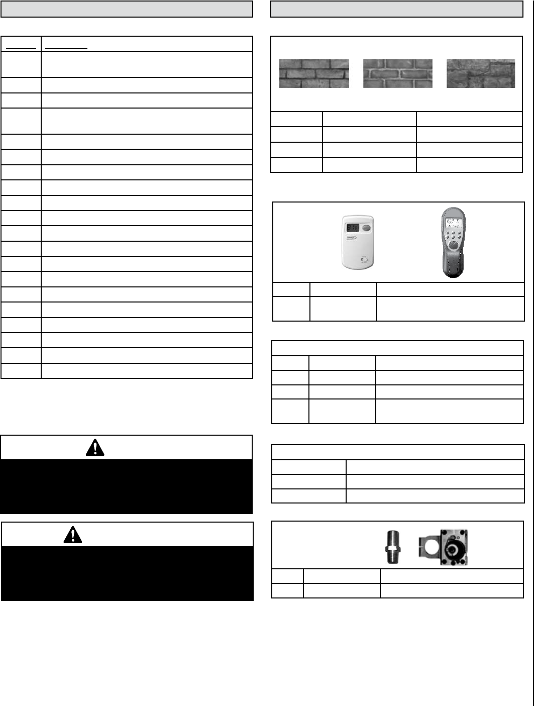
37
NOTE: DIAGRAMS & ILLUSTRATIONS ARE NOT TO SCALE.
Controls
H4635 DWTK Wall Thermostat, Digital
H0251 RCL-STAT Remote Control, RCL-STAT, Deluxe Thermo-
stat DC (ref. form #750129M)
Cat. No. Description
H3134 Cassette Assembly, NG (if LP, Also Requires 75064
Conversion Kit)
H6030 Burner Pan Assembly
H5922 Pilot Assembly (Convertible NG to LP)
H5942 Gas Control Valve NG (if LP, also Requires H5945 Regu-
lator Kit)
H5943 Regulator NG
H5945 Regulator LP
H5928 Main Burner Orifice #30 NG
H5929 Main Burner Orifice #49 LP
H3121 Blower W/Mounting Brackets
H5875 Blower Snap Switch
H5742 Blower Speed Control (rheostat)
H5744 On/Off Switch
H3119 On/Off Switch Wires
H5745 Piezo Igniter
H3120 Electrical Harness W/Inner Plate
H5859 Log Set
H5863 Bag of Embers / volcanic stone
H5864 Bag of Rockwool
H3101 Firebox Door W/Glass
H3123 Flue Restrictor Plates W/Hardware
Brick Panel Kits (ref. form #775269M)
Cat. No. Model Description
H7984 RAVL42-STD-BRK Standard Tan Brick
H7986 RAVL42-ARCHSTONE Architectural Stone
75356 RAVL42-RED-BRK Red Brick
Gas Conversion Kits
75095 RAVL42-CK-LP to NG Conversion Kit LP to NG (ref. form #775241M)
75064 RAVL42-CK-NG to LP Conversion Kit NG to LP (ref. form #775250M)
Misc.
75259 NP-RAVL30/42 Nail Plates (4 x 12) galvanized
75247 Reducer 8”-6 5/8” Reducer (8” to 6-5/8”)
75134 RAVL42-DUCTKT Ductability Kit (ref. form #775272M)
75260 RAVL42-DHHS, Dog House Heat Shield (for remote thermo-
stat) (ref. form #775207M)
ACCESSORIES
REPLACEMENT PARTS - Ravelle™ 42 (RAVL42)
Standard Tan Brick Architectural StoneRed Brick
Wall
Thermostat
Deluxe
Remote
Control
NOTE: The form numbers referenced are the part numbers of the instruction
sheets included in kits.
Knobs
75169 Gold (set of 2)
75170 Brushed Nickel (set of 2)
75010 Black Nickel (set of 2)
WARNING
Failure to position the parts in accordance with these
diagrams or failure to use only parts specifically
approved with this appliance may result in property
damage or personal injury.
AVERTISSEMENT
Risque de dommages ou de blessures si les pièces
ne sont pas installées conformément à ces schémas
et ou si des pièces autres que celles spécifiquement
approuvées avec cet appareil sont utilisées.
Contact an Authorized Lennox Hearth Products dealer to obtain any of
these parts. Never use substitute materials. Use of non-approved parts
can result in poor performance and safety hazards.
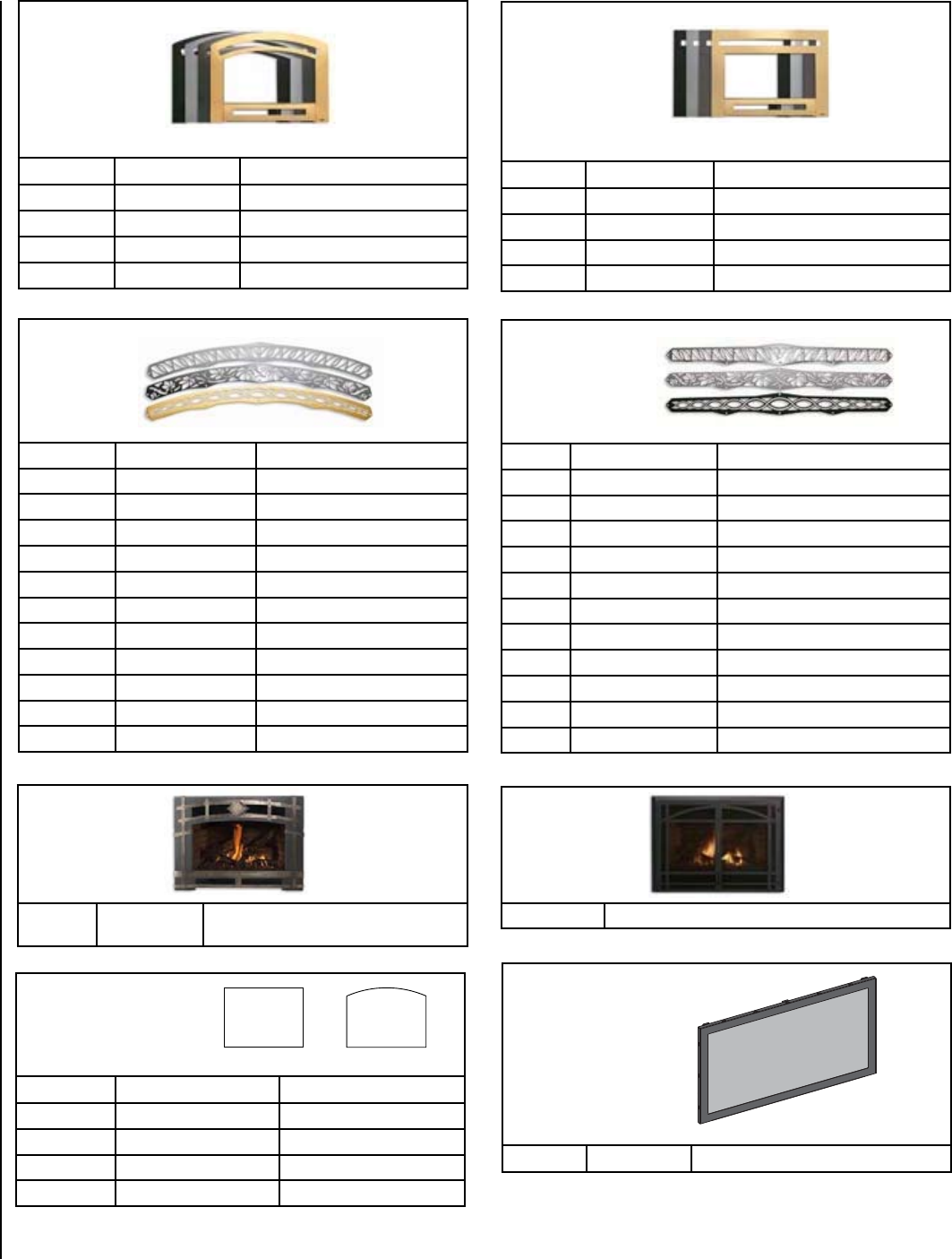
38 NOTE: DIAGRAMS & ILLUSTRATIONS ARE NOT TO SCALE.
Face Kits
Arched
(ref. form #775253M)
Cat. No. Model Description
75294 AIF42-BLK Black Face, Arched
75296 AIF42-GOLD Gold Face, Arched
75295 AIF42-NKL Brushed Nickel Face, Arched
75297 AIF42-BKNKL Black Nickel Face, Arched
Face Kits
Classic
Required to
Complete Face: Insets
(ref. form #775253M)
Cat. No. Model Description
75290 CIF42-BLK Black Face, Classic
75292 CIF42-GOLD Gold Face, Classic
75291 CIF42-NKL Brushed Nickel Face, Classic
75293 CIF42-BKNKL Black Nickel Face, Classic
Insets
(ref. form #775253M)
75322 AI42-ASPEN-BLK ASPEN Black
75324 AI42-ASPEN-GOLD ASPEN Gold
75323 AI42-ASPEN-BRNKL ASPEN Brushed Nickel
75325 AI42-ASPEN-BKNKL ASPEN Black Nickel
75338 AI42-NAPA-BLK NAPA Black
75340 AI42-NAPA-GOLD NAPA Gold
75339 AI42-NAPA-BRNKL NAPA Brushed Nickel
75341 AI42-NAPA-BKNKL NAPA Black Nickel
75314 AI42-TUSCAN-BLK TUSCAN Black
75316 AI42-TUSCAN-GOLD TUSCAN Gold
75315 AI42-TUSCAN-BRNKL TUSCAN Brushed Nickel
75317 AI42-TUSCAN-BKNKL TUSCAN Black Nickel
Screen Kit
(ref. form #775289M)
75029 Screen Face/double Door/black, 43-1/4”W x 31-7/8”H
INSETS (Required -
Includes 1 Top and
1 Bottom Inset)
(ref. form #775253M)
75326 CI42-ASPEN-BLK ASPEN Black
75328 CI42-ASPEN-GOLD ASPEN Gold
75327 CI42-ASPEN-BRNKL ASPEN Brushed Nickel
75329 CI42-ASPEN-BKNKL ASPEN Black Nickel
75318 CI42-NAPA-BLK NAPA Black
75320 CI42-NAPA-GOLD NAPA Gold
75319 CI42-NAPA-BRNKL NAPA Brushed Nickel
75321 CI42-NAPA-BKNKL NAPA Black Nickel
75342 CI42-TUSCAN-BLK TUSCAN Black
75344 CI42-TUSCAN-GOLD TUSCAN Gold
75343 CI42-TUSCAN-BRNKL TUSCAN Brushed Nickel
75345 CI42-TUSCAN-BKNKL TUSCAN Black Nickel
Barrier Screen Kit
(ref. form # 506033-23)
H7723 RAV42-BS Barrier Screen Kit
Foundry™
Face Kit
(ref. form #775286M)
75124 FOUNDRYF-42 BLACK FACE/Black Nickel Hand-Hammered
Straps
MASONRY TEMPLATES
(must be used if facing
material exceeds stove
body’s built-in 1” template)
(ref. form #775209M)
Cat. No. Model Description
75098 MT-ARCH42 Arched Template
75101 MT-CLS42 Classic Template
75035 MT-FOUNDRY42 Foundry™ Template
H7201 MT-SCREEN42 Screen Template
39
NOTE: DIAGRAMS & ILLUSTRATIONS ARE NOT TO SCALE.
IGN
DATE OF MANUFACTURE
20082010 20112009JAN FEB MAR APR MAY JUN JUL AUG SEP OCT NOV DEC
CAUTION: HOT WHILE IN OPERATION. DO NOT TOUCH. SEVERE BURNS MAY RESULT. KEEP
CHILDREN, CLOTHING, FURNITURE, GASOLINE AND OTHER LIQUIDS HAVING FLAMMABLE VAPORS AWAY.
KEEP BURNER AND CONTROL COMPARTMENT CLEAN. SEE INSTALLATION AND OPERATING INSTRUCTIONS
ACCOMPANYING APPLIANCE. FOR USE WITH GLASS DOORS CERTIFIED WITH THIS APPLIANCE ONLY. DO NOT
OPERATE THE APPLIANCE WITH GLASS REMOVED, CRACKED OR BROKEN. REPLACEMENT OF THE PANEL(S)
SHOULD BE DONE BY A LICENSED OR QUALIFIED PERSON.
WARNING: IMPROPER INSTALLATION, ADJUSTMENT, ALTERATION, SERVICE OR MAINTENANCE CAN CAUSE
INJURY OR PROPERTY DAMAGE. REFER TO THE OWNER’S INFORMATION MANUAL PROVIDED WITH THIS
APPLIANCE. FOR ASSISTANCE OR ADDITIONAL INFORMATION CONSULT A QUALIFIED INSTALLER, SERVICE
AGENCY OR GAS SUPPLIER.
MODEL
MODÈLE
RAVELLE™ 42
MANUFACTURED BY / FABRIQUÉ PAR:
LENNOX HEARTH PRODUCTS
PO BOX 987
AUBURN, WA., USA 98071
RAVL42
SERIAL
NO.
Report No. / Número de Rapport
050-S-08c-5
LISTED VENTED GAS FIREPLACE HEATER - NOT FOR USE WITH SOLID FUEL
TESTED TO ANSI Z21.88-2005/CSA 2.33-2005 “VENTED GAS FIREPLACE HEATERS”, UL307b, CSA P.4.1-02, AND CGA 2.17-M91.
THIS APPLIANCE MUST BE INSTALLED IN ACCORDANCE WITH LOCAL CODES, IF ANY. IF NOT, FOLLOW THE CURRENT ANSI Z223.1/NFPA
54-LATEST EDITION (USA) OR CAN/CGA B149.1-LATEST EDITION (CANADA). THIS APPLIANCE MUST BE INSTALLED IN ACCORDANCE
WITH THE MANUFACTURER’S INSTALLATION INSTRUCTION. FOR INSTALLATION IN SOLID FUEL BURNING FIREPLACES ONLY - MASONRY
OR FACTORY BUILT. THIS VENTED GAS FIREPLACE HEATER IS NOT FOR USE WITH AIR FILTERS.
THIS APPLIANCE IS ONLY FOR USE WITH THE TYPE OF GAS INDICATED ON THE RATING PLATE AND MAY BE INSTALLED IN AN
AFTERMARKET, PERMANENTLY LOCATED, MANUFACTURED (MOBILE) HOME WHERE NOT PROHIBITED BY LOCAL CODES. SEE OWNER’S
MANUAL FOR DETAILS. THIS APPLIANCE IS NOT CONVERTIBLE FOR USE WITH OTHER GASES UNLESS A CERTIFIED KIT IS USED. MAY BE
INSTALLED IN RESIDENTIAL BEDROOMS.
DANGER: RISK OF ELECTRICAL SHOCK. DISCONNECT POWER BEFORE SERVICING UNIT.
IF ELECTRICALLY CONNECTED, CONNECTIONS AND GROUNDING MUST BE IN ACCORDANCE WITH LOCAL CODES, IF ANY. IF NOT,
FOLLOW THE CURRENT NATIONAL ELECTRICAL CODE ANSI/NFPA 70-LATEST EDITION (USA) OR CSA C22-1-LATEST EDITION (CANADA).
DO NOT REMOVE OR COVER THIS LABEL
Part No./ No. pièce #36202 Rev. A, 06/2007
FACTORY EQUIPPED FOR NATURAL GAS. IF CONTROL PANEL CONTRADICTS THIS LABEL, UNIT FUEL TYPE HAS BEEN CONVERTED.
CET APPAREIL EST MUNI D’ÉQUIPEMENT POUR L’USAGE DU GAZ NATUREL. SI L’ÉTIQUETTE DU PANNEAU DES COMMANDES CONTREDIT CETTE
ÉTIQUETTE, C’EST QUE LE TYPE DE CARBURANT DE CET APPAREIL A ÉTÉ CONVERTI.
MINIMUM CLEARANCES TO COMBUSTIBLES IN INCHES
Front corners to enclosure (from stand-offs) 0 Hearth Extension - not required but recommended
Back to enclosure (from stand-offs) 0 Rear corners to enclosure (from stand-offs) 0
Top to header (from stand-offs) 0 Base of unit to mantel 47-5/8
Bottom of unit to floor 0 Base of unit to top trim/facing 41-5/8
Side trim or wall to edge of door glass 7.5
See owner’s manual for additional clearance information on mantels and direct vent pipe.
NG LP NG LP
Input Rate on “HI” (BTU/H) 42,000 36,000 Minimum Inlet Pressure (in. WC) 5 11
Input Rate on “LO” (BTU/H) 29,500 25,000 Manifold Pressure on “HI” (in. WC) 3.5 10
Orifice Size (DMS) #30 #49 Manifold Pressure on “LO” (in. WC) 1.7 5.1
Blower Electrical Rating: 120 VAC, 60 Hz, Less Than 2 Amps
*Unit factory equipped for 0-2000 ft/0-610 m, in Canada 0-4500 ft/0-1370 M. For altitudes above 2,000 ft/610m (in Canada 4500 ft/1370m) de-rate
the appliance by four (4)% for every 1,000 ft (405 m).
See owner’s manual for instructions on changing cassette/valve assembly.
HOMOLOGUÉ FOYER RADIANT PRÉFABRIQUÉ AU GAZ - INSERTION DE FOYER AU GAZ - NE PAS UTILISER
AVEC DU COMBUSTIBLE SOLIDE
TESTÉ SELON LA NORME ANSI Z21.88-2005/CSA 2.33-2005 «FOYER RADIANT AU GAZ», UL307B, CSA P.4.1-02, ET CGA 2.17-M91.
CET APPAREIL DOIT ÊTRE INSTALLÉ CONFORMÉMENT AUX EXIGENCES DES CODES RÉGIONAUX ET DU CODE D’INSTALLATION ANSI
NFPA 54-DERNIÈRE ÉDITION (ETATS-UNIS), OU CAN/CGA-B149.1-DERNIÈRE ÉDITION (CANADA). CET APPAREIL DOIT ÊTRE INSTALLÉ
SELON LES DIRECTIVES D’INSTALLATION DU FABRICANT. POUR INSTALLATION DANS DES FOYERS À COMBUSTIBLE SOLIDE SEULEMENT
- DE MAÇONNERIE OU PRÉFABRIQUÉ EN USINE. CE FOYER RADIANT AU GAZ À ÉVACUATION N’EST PAS CONÇU POUR ÊTRE UTILISÉ
AVEC DES FILTRES À AIR. CET APPAREIL DOIT ÊTRE UTILISÉ AVEC LE TYPE DE GAZ INDIQUÉ SUR LA PLAQUE SIGNALÉTIQUE ET PEUT
ÊTRE INSTALLÉ DANS UNE MAISON PRÉUSINÉE OU DANS UNE MAISON MOBILE FIXE, LÀ OÙ LES CODES RÉGIONAUX LE PERMETTENT.
VOIR LE MANUEL D’ENTRETIEN POUR PLUS DE DÉTAILS. CET APPAREIL NE PEUT PAS ÊTRE CONVERTI POUR L’USAGE AVEC D’AUTRES
TYPES DE GAZ À MOINS D’UTILISER UNE TROUSSE DE CONVERSION HOMOLOGUÉE.
DANGER: RISQUE DE CHOC ÉLECTRIQUE. DÉBRANCHEZ L’APPAREIL AVANT D’EN FAIRE L’ENTRETIEN.
SI L’APPAREIL REQUIERT UN BRANCHEMENT ÉLETRIQUE, LES RACCORDEMENTS ET LA MISE À LA TERRE DOIVENT ÉTRE CONFORMES
AUX EXIGENCES DES CODES RÉGIONAUX ET DU CODE D’INSTALLATION ANSI/NFPA 70 OU CSA C22-1.
DANGER: CET APPAREIL DÉGAGE DES TEMPÉRATURES ÉLEVÉES ET DEVRAIT ÊTRE INSTALLÉ À L’ÉCART DES
ENDROITS TRÈS PASSANTS ET LOIN DES MEUBLES ET RIDEAUX. SURVEILLEZ LES ENFANTS QUI SE TROUVENT DANS LA PIÈCE.
GARDEZ LA ZONE AUTOUR DU FOYER EXEMPTE DE MATÉRIAUX COMBUSTIBLES, D’ESSENCE ET AUTRES VAPEURS ET LIQUIDES
INFLAMMABLES. MAINTENEZ LE BRÛLEUR ET LE BOÎTIER DES COMMANDES PROPRE EN TOUT TEMPS. VOIR LES MANUELS
D’INSTALLATION ET D’ENTRETIEN QUI ACCOMPAGNENT L’APPAREIL. SEUL LE PANNEAU VITRÉ FOURNI PAR LE MANUFACTURIER
PEUT ÊTRE UTILISÉ AVEC CET APPAREIL. EN AUCUN CAS, L’APPAREIL NE PEUT ÊTRE UTILISÉ SANS LA VITRE OU AVEC LA VITRE
BRISÉE. LE REMPLACEMENT DE LA VITRE DOIT ÊTRE EFFECTUÉ PAR UN TECHNICIEN DE SERVICE QUALIFIÉ.
AVERTISSEMENT: UNE INSTALLATION INADÉQUATE DE MÊME QU’UN AJUSTEMENT, UNE MODIFICATION, UNE RÉPARATION OU UN
ENTRETIEN INCORRECTS PEUVENT CAUSER DES BLESSURES OU DOMMAGES À LA PROPRIÉTÉ. RÉFÉREZ-VOUS AU MANUEL
D’ENTRETIEN LIVRÉ AVEC CET APPAREIL. POUR DE L’ASSISTANCE, CONSULTEZ UN INSTALLATEUR QUALIFIÉ, UNE ENTREPRISE
DE SERVICE OU UN FOURNISSEUR DE GAZ.
IGN 07-2554
N’ENLEVEZ PAS OU NE COUVREZ PAS CETTE ÉTIQUETTE
SPÉCIFICATIONS
NG LP NG LP
Entrée Max/min BTU/hr 0-4500 Pi (0-1370 M)*
42,000 36,000 Pression Minimum D’entrée Du Gaz
(IN. WC/C.E.)
5 11
Entrée Minimum BTU/hr 0-4500 Pi (0-1370 M)*
29,500 25,000 Pression À La Sortie - HI
(IN. WC/C.E.)
3.5 10
Orifice (DMS)* #30 #49 Pression À La Sortie - LO
(IN. WC/C.E.)
1.7 5.1
Spécifications Électrique 120 Vca, 60 Hz, Moins De 2 Ampères
*En altitude, au-delà de 2000 pi/610 m, (au canada 0-4500 pi/0-1370m) la capacité énergétique de l’appareil diminue de quatre (4)% pour chaque
1000 pi (405 m).
Référez-vous au manuel d'instructions du propriétaire pour changer le bloc d'assemblage de la valve.
DÉGAGEMENTS AUX COMBUSTIBLES - EN POUCES (MILLIMÈTRES)
Coins avant au caisson (depuis les espaceurs) 0 (0mm) Extension d’âtre - Prolongement de l'âtre - Non requis mais recommandé
Du dos au caisson (depuis les espaceurs) 0 (0mm) Côtés arrière au caisson (depuis les espaceurs) - 0 (0mm)
Du dessus au support (depuis les espaceurs) 0 (0mm) De la base de l’unité au manteau - 47-5/8"" (1210mm)
Du fond de l’unité au plancher 0 (0mm) De la base de l’unité à la finition/ façade du dessus - 41-5/8" (1057mm)
De la finition du côté ou du mur au bord de la vitre 7-1/2 (191mm)
Voir le manuel d’installation pour plus d’informations sur les dégagements requis au manteau, conduits direct-vent et prolongement de
l’’âtre.
MODEL
MODÈLE
RAVELLE™ 42
MANUFACTURED BY / FABRIQUÉ PAR:
LENNOX HEARTH PRODUCTS
PO BOX 987
AUBURN, WA., USA 98071
SERIAL
NO.
Report No. / Número de Rapport
050-S-08c-5
No. pièce #36264 Rev. A, 06/2007
CET APPAREIL EST MUNI D’ÉQUIPEMENT POUR L’USAGE DU GAZ NATUREL. SI L’ÉTIQUETTE DU PANNEAU DES COMMANDES CONTREDIT CETTE
ÉTIQUETTE, C’EST QUE LE TYPE DE CARBURANT DE CET APPAREIL A ÉTÉ CONVERTI.
Le numéro de série est indiqué dans
la section anglophone de cette étiquette
Le date de fabrication est indiquée dans la section anglophone de cette étiquette
US
Portland
US
Portland
SAFETY / LISTING LABEL - FRENCH
SAFETY / LISTING LABEL - ENGLISH
2010 2011 2012 2013
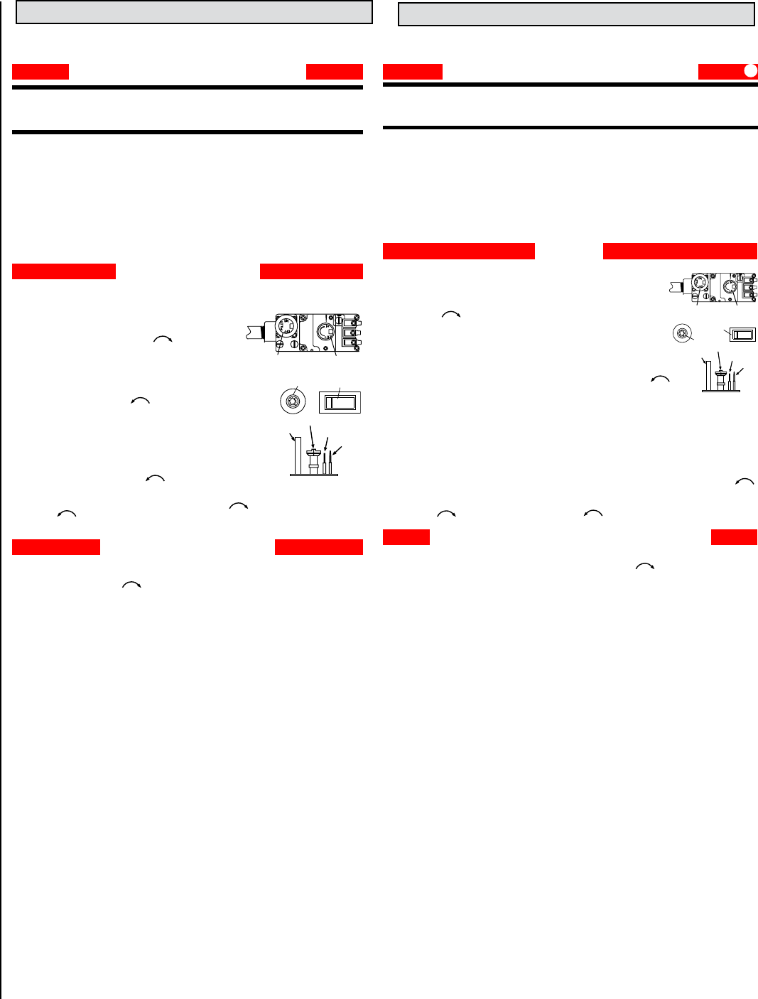
40 NOTE: DIAGRAMS & ILLUSTRATIONS ARE NOT TO SCALE.
CAUTION: YOUR LENNOX™ GAS APPLIANCE MUST ALWAYS BE OPERATED WITH GLASS DOOR IN PLACE.
STOP! Read the safety information above before proceeding.
1.
Open the lower access door.
Make sure gas supply shut-off cocks are open and ON/OFF
Rocker Switch is “OFF”. If equipped with a thermostat, set it to the lowest setting.
2. Turn off all electrical power to the appliance.
3. Push in Gas Control Knob slightly and turn clockwise to “OFF”.
NOTE: Knob cannot be turned from “PILOT” to “OFF” unless Knob is pushed in slightly. Do
not force.
4. Wait five (5) minutes to clear out any gas. If you smell gas, STOP! Follow “B” above. If you
don’t smell gas continue.
5. Locate the pilot by looking through the “V” in the left front lower log. Blue flame will be seen when the
pilot is lit.
6. Turn the gas control knob counterclockwise to the “PILOT” position.
7. Push the knob all the way in and hold in that position. Immediately light the pilot by pressing the ignitor
button several times until pilot is lit. Continue to hold the knob in for about 30 seconds after the pilot is
lit. Release knob and it will pop back out.
Pilot should remain lit. If it goes out, repeat steps 4-8 holding knob in an additional 15 seconds after pilot
is lit.
• If knob does not pop out when released, stop and immediately call your service technician or gas supplier.
• If the pilot will not stay lit after several tries, turn the gas control knob to “OFF” and call your service
technician or your gas supplier.
8. After pilot is lit, turn gas control counterclockwise to “ON”. Knob can only be turned “ON” if the
knob has popped out.
9. To turn burner on, turn “ON/OFF” rocker switch to “ON” or set the thermostat to the desired temperature above room temperature.
10. Adjust the flame height (and heat output) by turning the flame height knob clockwise for reduced flame and counterclockwise
for full flame.
11. Set the blower to the desired air flow after it turns on when the appliance reaches operating temperature.
FOR YOUR SAFETY READ BEFORE OPERATING
1. To turn off the burner, switch the rocker switch to “OFF” or adjust the thermostat to a setting below room temperature
(if installed). The pilot will remain lit for future burner ignition.
For complete shutdown: See “TO TURN OFF GAS TO APPLIANCE” above.
SHUTDOWN PROCEDURE
OPERATING INSTRUCTIONS
WARNING:
IF YOU DO NOT FOLLOW THESE INSTRUCTIONS EXACTLY, A FIRE OR EXPLOSION MAY RESULT CAUSING
PROPERTY DAMAGE, INJURY OR LOSS OF LIFE.
CAUTION:
HOT WHILE IN OPERATION. DO NOT TOUCH. KEEP CHILDREN, FURNITURE, GASOLINE AND OTHER LIQUIDS WITH
FLAMMABLE VAPORS AWAY. NEVER OPERATE UNIT WITH GLASS DOOR OFF OR ATTEMPT TO OPEN THE DOOR WHILE HOT.
A. This appliance is equipped with a piezo ignition device to light the pilot. When lighting the pilot, follow these instructions exactly.
B. BEFORE LIGHTING, smell around the appliance area for gas. Be sure to smell next to the floor because some gas is heavier than air
and will settle on the floor.
WHAT TO DO IF YOU SMELL GAS:
• DO NOT try to light the appliance.
• DO NOT touch any electric switch; do not use any phone in the building.
• Immediately call your gas supplier from a neighbor's phone. Follow the gas supplier's instructions.
• If you cannot reach your gas supplier, call the fire department.
C. Use only your hand to push in or turn the gas control knob. Never use any tool. If the knob will not push in or turn by hand, don't try
to repair it, call a qualified service technician. Force or attempted repair may result in a fire or explosion.
D. DO NOT use this appliance if any part has been under water. Immediately call a qualified service technician to inspect the appliance
and to replace any part of the control system and any gas control which has been under water.
1. Turn off the “ON/OFF” rocker switch and/or thermostat (if installed).
2. Turn off electric power to the appliance if service is to be performed.
3. Turn gas control knob clockwise to "OFF". Do not force.
This appliance needs fresh air for safe operation and must be installed so there are provisions for adequate
combustion and ventilation air. See Installation and Operation Manual accompanying appliance.
WARNING: Improper installation, adjustment, alteration, service or maintenance can
cause injury or property damage. For assistance or additional information, consult a
qualified installer, service agency or your gas supplier.
Operation of this appliance when not connected to a properly installed and maintained venting system can result
in carbon monoxide (CO) poisoning and possible death.
TO TURN OFF GAS TO APPLIANCE
#36202 Rev. A, 06/2007 IGN
SIT Millivolt Gas Valve
Gas Control Knob
(Pilot / On / Off)
Flame Height Control Knob
(HI / LO)
OFF
ON
Piezo Igniter ON/OFF Switch
MILLIVOLT PILOT
Thermopile Igniter (electrode)
Thermocouple
Gas Pilot Hood
POUR VOTRE SÉCURITÉ, LIRE AVANT L’ALLUMAGE
1. Fermez l’interrupteur et/ou le thermostat «MARCHE/ARRÊT».
2. Coupez l’alimentation électrique de l’appareil si vous prévoyez en faire le service.
3. Tournez le bouton de commande du gaz dans le sens des aiguilles d’une montre à “OFF”. Ne le forcez pas.
Cet appareil a besoin d’air frais pour opérer sécritairement et doit être installé pour qu’il y ait un apport en air suffisant. Référez-vous aux
manuels d’entretien et d’installation fournis avec l’appareil.
AVERTISSEMENT: Une installation inadéquate, un mauvais ajustement, une altération ou toutes autres modifications
inappropriés pourraient entraîner des blessures physiques et/ou des dommanges matériels. Référez-vous au guide
d’utilisation fourni avec ce foyer. Pour assistance ou information supplémentaires contactez un installateur qualifié, un agent
de service ou un fournisseur de gaz.
Si vous opérez cet appareil sans qu’il ne soit correctement raccordé à un conduit d’évacuation, vous pourriez risquer d’être empoisonné au
monoxyde de carbone (CO) ce qui pourrait entraîner des conséquences grave ou la mort.
POUR COUPER L’ALIMENTATION EN GAZ DE L’APPAREIL
1. Pour arrêter le brûleur, mettre l’interrupteur à la position “OFF” ou ajustez le thermostat à une température en dessous de
la température ambiante. La veilleuse restera allumée pour permettre un alummage ultérieur.
Pour un arrêt complet: Consultez la procédure ci-dessus «POUR COUPER L’ALIMENTATION EN GAZ DE L’APPAREIL».
PROCÉDURE D’ARRÊT
ALLUMAGE
AVERTISSEMENT:
SI VOUS NE RESPECTEZ PAS RIGOUREUSEMENT LES INSTRUCTIONS CI-DESSOUS, VOUS POURRIEZ ENCOURIR UN RISQUE D’INCENDIE ET/OU D’EXPLOSION
QUI POURRAIENT CAUSER DES DOMMANGES MATÉRIELS ET CORPORELS POUVANT ENTRAÎNER LA MORT.
DANGER:
CET APPAREIL DÉGAGE DES TEMPÉRATURES ÉLEVÉES ET DEVRAIT ÊTRE INSTALLÉ À L’ÉCART DES ENDROITS TRÈS PASSANTS ET LOIN DES MEUBLES ET RIDEAUX.
GARDEZ LA ZONE AUTOUR DU FOYER EXEMPTE DE MATÉRIAUX COMBUSTIBLES, D’ESSENCE ET AUTRES VAPEURS ET LIQUIDES INFLAMMABLES.
A. Cet appareil utilise un système d’allumage par étincelle (allumeur Piézo-électrique) pour allumer la veilleuse. Assurez-vous de suivre
rigoureusement les instructions d’allumage de la veilleuse.
B. AVANT D’ALLUMER L’APPAREIL, assurez-vous qu’il n’y a pas d’odeur de gaz près de l’appareil ni près du sol car certains gaz plus
lourds que l’air auraient tendance à s’y accumuler en cas de fuite.
QUE FAIRE SI VOUS SENTEZ UNE ODEUR DE GAZ:
• N’ALLUMEZ aucun appareil.
• Ne touchez aucune prise électrique; N’utilisez aucun téléphone dans votre édifice.
• Sortez de la maison. À partir d’un autre endroit, appelez immédiatement votre fournisseur de gaz et suivez les directives.
• S’il est impossible de joindre le distributeur du gaz, appelez les pompiers.
C. N’utilisez aucun outil pour tourner ou pousser le dispositif de contrôle du gaz. Si vous ne pouvez le faire manuellement, n’essayez
pas de réparer l’appareil. Appelez un technicien de service qualifié. Si vous tentez de forcer ou réparer le dispositif de contrôle du gaz
vous pourriez encourir un risque d’incendie et/ou d’explosion.
D. N’utilisez pas cet appareil si une de ses composantes a été émergée dans l’eau. Appelez immédiatement un technicien de service
qualifié et reconnu afin qu’il inspecte et remplace au besoin toutes pièces du système qui auraient été en contact avec l’eau.
DANGER: VOTRE APPAREIL AU GAZ LENNOX DOIT ÊTRE OPÉRÉ AVEC DES PORTES DE VERRE.
ATTENTION! Lisez les consignes de sécurité ci-dessous avant d’opérer votre appareil.
1. Ouvrir la porte du bas. Assurez-vous que l’alimentation en gaz est à la position Fermée
“OFF”. Si l’appareil est équippé d’un thermostat, placez-le à la température la plus basse.
2. Couper le courant électrique qui alimente l’appareil.
3. Enfoncez légèrement le bouton de contrôle du gaz et tournez-le dans le sens des aiguilles
d’une montre à la position “OFF”.
NOTE: Le bouton de contrôle du gaz ne peut être tourné de la position “PILOT” à “OFF”
sans qu’une légère pression ne soit appliquée.
4. Attendez au moins 5 minutes pour que le gaz qui se trouve dans la chambre de combustion
puissse s’échapper. Si vous sentez une odeur de gaz ARRÊTEZ! Référez-vous à la section B
ci-dessus. Si vous ne sentez pas d’odeur de gaz, allez à la prochaine étape.
5. Vous pouvez aussi voir le pilote en regardent à travers le V situer dans le bas de la bûche gauche
avant. Une amme bleue est visible lorsque le veilleuse est allumée.
6. Tournez le bouton de contrôle de gaz dans le sens inverse des aiguilles d’une montre
pour le placer sur “PILOT”.
7. Cet appareil de chauffage est equipé d’un système d’allumage par étincelle (allumeur Piézo-
électirque), devant être utilisé pour l’allumage de la veilleuse. Poussez complètement le bouton de contrôle du gaz et le
maintenir dans cette position. Appuyez immédiatement sur le bouton (allumeur Piézo-électrique) situé à gauche du robinet
de contrôle du gaz.L’étincelle produite par l’allumeur Piézo-électrique doit allumer la veilleuse. Continuez à maintenir le
bouton de contrôle dans cette position pendant environ 30 secondes après l’allumage de la veilleuse. Relâchez le bouton
de contrôle du gaz qui reviendra à la position initiale. La veilleuse doit rester allumée. Répétez les étapes 4 à 8 pendant 15
secondes supplémentaires si la veilleuse s’éteind.
•`Si le bouton de contrôle du gaz ne revient pas à la position initiale une fois relâché, appeler immédiatement un technicien
qualié ou votre distributeur de gaz.
•`Si la veileuse ne reste pas allumée après plusieurs essais, tournez le bouton de contrôle du gaz à la position “OFF” et
appelez immédiatement un technicien qualié ou votre distributeur de gaz.
8. Lorsque la veilleuse est allumée, tournez le bouton de contrôle du gaz dans le sens invers des aiguilles d’une montre
pour le placer à la position “ON”. Le bouton de contrôle peut-être tourné à la position “ON” seulement si il n’est plus enfoncé.
9. Pour allumer le brûleur, mettre l’interrupteur à la position “ON” ou ajustez le thermostat à la température souhaitée.
10. Ajustez la amme et la température souhaitée en tournant le bouton de réglage de la amme dans les sens des aiguille
d’une montre pour l’abaisser et dans le sens contraire pour l’augmenter.
11. Ajustez le ventilateur au volume désiré lorsque l’appareil aura atteint la température de fonctionnement.
IGN 07-2554
No. pièce
#36264 Rev. A, 06/2007
MILLIVOLT PILOT
Thermopile
Veilleuse à gaz
Allumeur
Thermocouple
OFF
ON
Allumeur
Interrupteur
Millivolt Pilot
SIT Millivolt Gas Valve
Flame Height Control
Knob (HI / LO)
Gas Control Knob
(Pilot / On / Off)
LIGHTING LABEL - FRENCH
LIGHTING LABEL - ENGLISH

41
NOTES
Printed in U.S.A. © 2007 Lennox Hearth Products
P/N 775,219M REV. D 03/2010
Lennox Hearth Products reserves the right to make changes at any time, without notice, in
design, materials, specifications, prices and also to discontinue colors, styles and products.
Consult your local distributor for fireplace code information.
42
WARRANTY
Your gas fireplace is covered by a limited warranty (provided with
appliance). Please read the warranty to be familiar with its coverage.
Retain this manual. File it with your other documents for future refer-
ence.
PRODUCT REFERENCE INFORMATION
We recommend that you record the following important information
about your appliance. Please contact your Lennox Hearth Products dealer
for any questions or concerns. For the number of your nearest Lennox
Hearth Products dealer, please call 1-800-9-LENNOX.
REPLACEMENT PARTS
See Page 37 for a complete replacement parts list. Use only parts sup-
plied from the manufacturer.
Normally, all parts should be ordered through your Lennox distributor or
dealer. Parts will be shipped at prevailing prices at time of order.
When ordering repair parts, always give the following information:
1. The model number of the appliance.
2. The serial number of the appliance.
3. The part number.
4. The description of the part.
5. The quantity required.
6. The installation date of the appliance.
If you encounter any problems or have any questions concerning the
installation or application of this system, please contact your dealer.
LENNOX HEARTH PRODUCTS
1508 Elm Hill Pike, Suite 108
Nashville, TN 37210
Visit us at www.Lennox.com
Your Fireplace's Model Number ________________________________________
Your Fireplace’s Serial Number ________________________________________
The Date On Which Your Fireplace Was Installed ___________________________
Your Dealer's Name _________________________________________________
Fuel Type (Check one) cNatural Gas cPropane Gas (LP)
1508 Elm Hill Pike, Suite 108 • Nashville, TN 37210
