Mimosa Networks 010-00083 24 GHz Backhaul Radio User Manual
Mimosa Networks, Inc. 24 GHz Backhaul Radio
User Manual

Mimosa Backhaul
copyright © 2018 Mimosa. All rights reserved.
http://backhaul.help.mimosa.co/
The information contained in this document is subject to change without notice.
This document contains proprietary information which is protected by copyright.
All rights are reserved. No part of this document may be photocopied, reproduced,
or translated to another language without the prior written consent of Mimosa.

Mimosa Backhaul and B24 Help Content
Mimosa Backhaul LED Status Indicators
Copyright © 2018 Mimosa Page
Table of Contents
Installation Guide 1 .......................................................................................................................................
Mounting & Grounding 1 ........................................................................................................................
B24 Mounting and Grounding 1 .......................................................................................................
B24 Installation, Mounting and Alignment 4 ....................................................................................
User Guide 7 ..................................................................................................................................................
Overview 7 .............................................................................................................................................
General 7 .........................................................................................................................................
Accessing the Interface 9 ................................................................................................................
Logging In 10 ...................................................................................................................................
User Interface Overview 11 .............................................................................................................
Dashboard 13 .........................................................................................................................................
Dashboard Overview 13 ..................................................................................................................
Signal Meter 14 ...............................................................................................................................
Aiming Mode 17 ...............................................................................................................................
Performance 19 ...............................................................................................................................
Device Details 21 ............................................................................................................................
MIMO Status 24 ...............................................................................................................................
Wireless 27 .............................................................................................................................................
Channel & Power 27 ........................................................................................................................
Spectrum Analyzer 27 ..............................................................................................................
Channel & Power Settings 29 ...................................................................................................
Exclusions & Restrictions 34 .....................................................................................................
Link 35 .............................................................................................................................................
TDMA Configuration 35 .............................................................................................................
Rate Adaptation 37 ...................................................................................................................
Link Configuration 38 ...............................................................................................................
Location 41 ......................................................................................................................................
Local Satellite Signals 41 ..........................................................................................................
Satellite Information 42 ............................................................................................................
Location Data 43 ......................................................................................................................
Site Survey 44 .................................................................................................................................
Survey Results 44 .....................................................................................................................
Preferences 45 .......................................................................................................................................
General 45 .......................................................................................................................................
Naming 45 ................................................................................................................................
Time 46 ....................................................................................................................................
Set Password 47 .......................................................................................................................
Miscellaneous 48 ......................................................................................................................
Management 50 ..............................................................................................................................
Management IP 50 ...................................................................................................................
Watchdog 51 ............................................................................................................................
Services 52 ...............................................................................................................................
Miscellaneous Settings 53 ........................................................................................................

Mimosa Backhaul and B24 Help Content
Mimosa Backhaul LED Status Indicators
Copyright © 2018 Mimosa Page
Network Interfaces 55 ..............................................................................................................
Management VLAN 57 ..............................................................................................................
2.4 GHz Console 58 .........................................................................................................................
2.4 GHz Network 58 .................................................................................................................
2.4 GHz Security 59 ..................................................................................................................
Notifications 60 ...............................................................................................................................
SNMP Notifications 60 ..............................................................................................................
SNMP Traps 61 .........................................................................................................................
SNMP Traps OIDs 63 .................................................................................................................
System Log Notifications 65 .....................................................................................................
System Log Traps 66 ................................................................................................................
Firmware & Reset 67 .......................................................................................................................
Firmware Update 67 .................................................................................................................
Reset & Reboot 68 ...................................................................................................................
Backup & Restore 69 .......................................................................................................................
Backup & Restore 69 ................................................................................................................
Diagnostics 70 ........................................................................................................................................
Tests 70 ...........................................................................................................................................
Test Overview 70 .....................................................................................................................
Ping 71 .....................................................................................................................................
Bandwidth 72 ...........................................................................................................................
Traceroute 73 ...........................................................................................................................
Logs 74 ............................................................................................................................................
Log Overview 74 .......................................................................................................................
Troubleshooting Guide 75 .............................................................................................................................
LED Status Indicators 75 ........................................................................................................................
B24 LED Status Indicators 75 ..........................................................................................................
Mimosa Backhaul and B24 Help Content
Mimosa Backhaul Mounting & Grounding
Copyright © 2018 Mimosa Page Page 1
Mounting and Grounding the B24
Only a shielded, outdoor rated CAT 6 FTP Ethernet cable shall be used with all Mimosa products. Mimosa
Only a shielded, outdoor rated CAT 6 FTP Ethernet cable shall be used with all Mimosa products. Mimosa
will not warrant any product which has been installed without the use of shielded CAT 6 Ethernet cable
will not warrant any product which has been installed without the use of shielded CAT 6 Ethernet cable
and/or proper earth grounding.
and/or proper earth grounding.
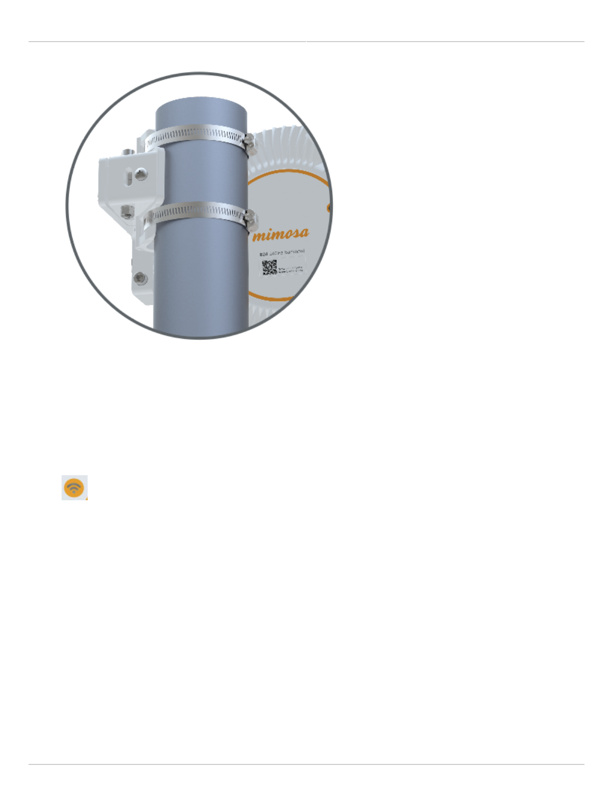
This process ensures that the radio is securely attached to a mast/pole up to 90 mm (3.5 inches) in
This process ensures that the radio is securely attached to a mast/pole up to 90 mm (3.5 inches) in
diameter, and grounded to protect against electrical discharge.
diameter, and grounded to protect against electrical discharge.
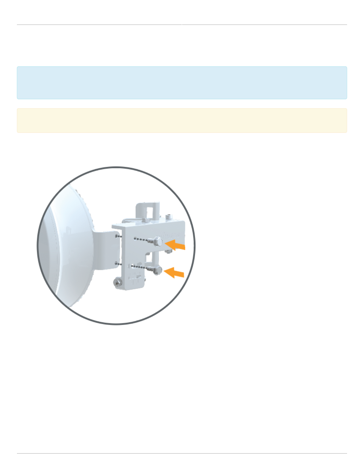
Follow these steps to mount and ground the B24 Radio.
Attach the precision alignment mount to the bracket with the provided bolts.1.
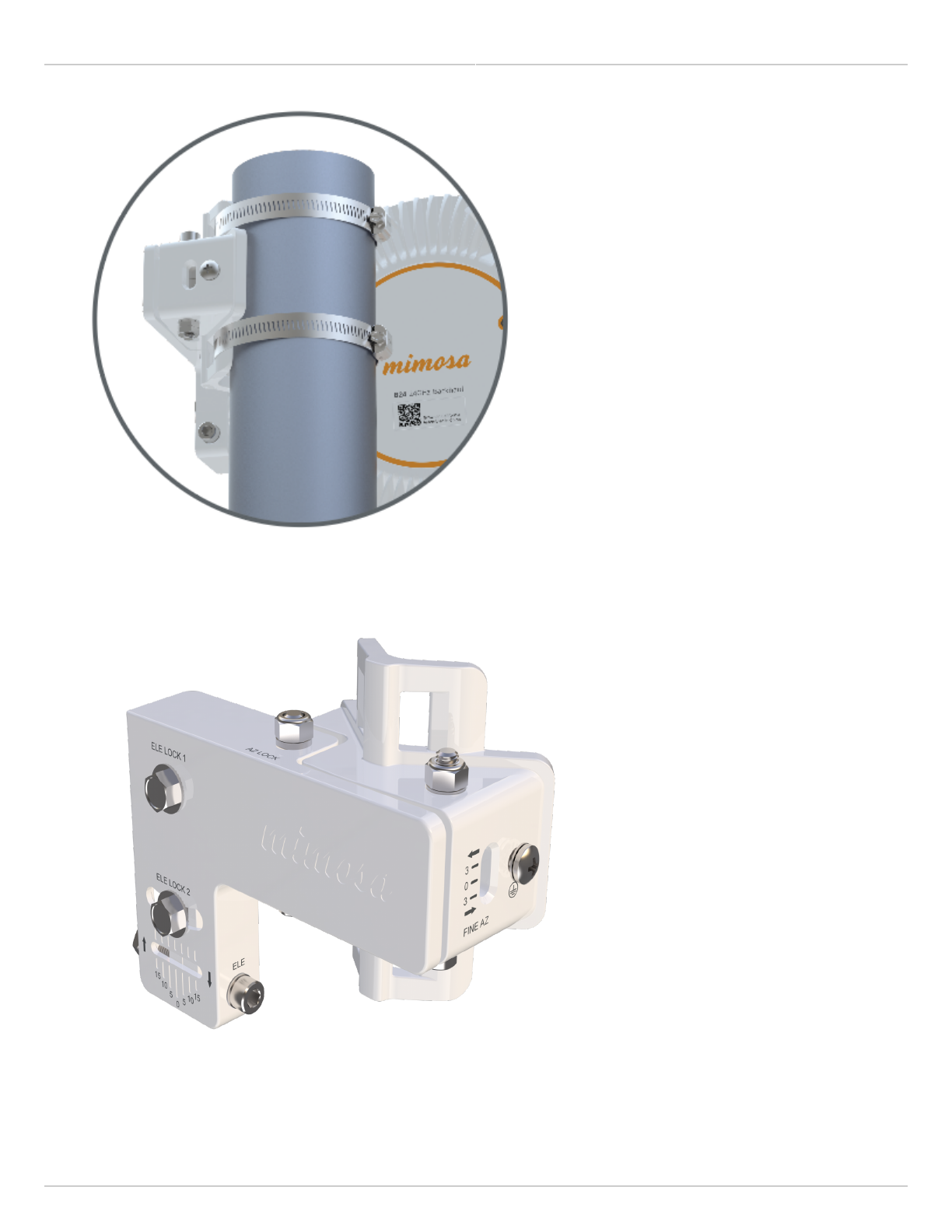
Attach the mount to your desired pole using the provided pole clamps.2.
Mimosa Backhaul and B24 Help Content
Mimosa Backhaul Mounting & Grounding
Copyright © 2018 Mimosa Page Page 2
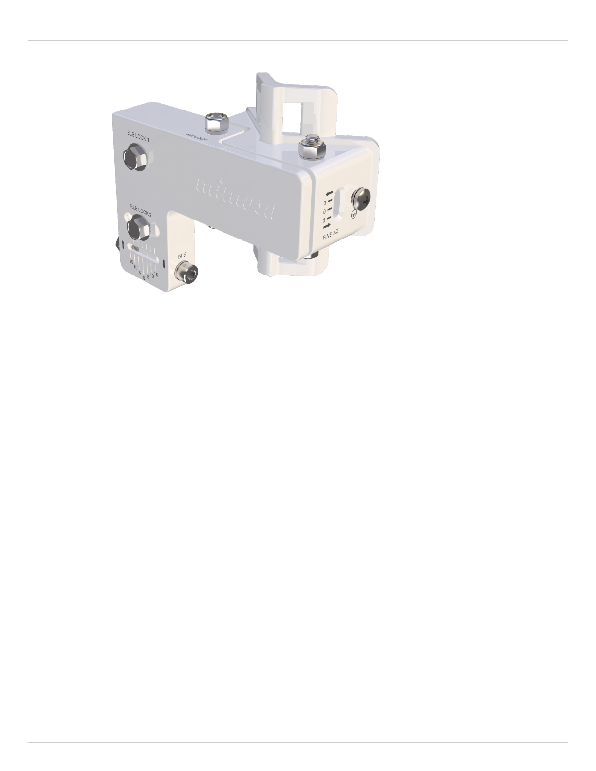
Aim the radio horizontally by sliding the the mount around pole until it is pointing in the desired direction. To3.
fine tune the radio, use the Elevation and Azimuth adjustment allen bolts, then check and tighten each of
Elevation and Azimuth locking bolts.
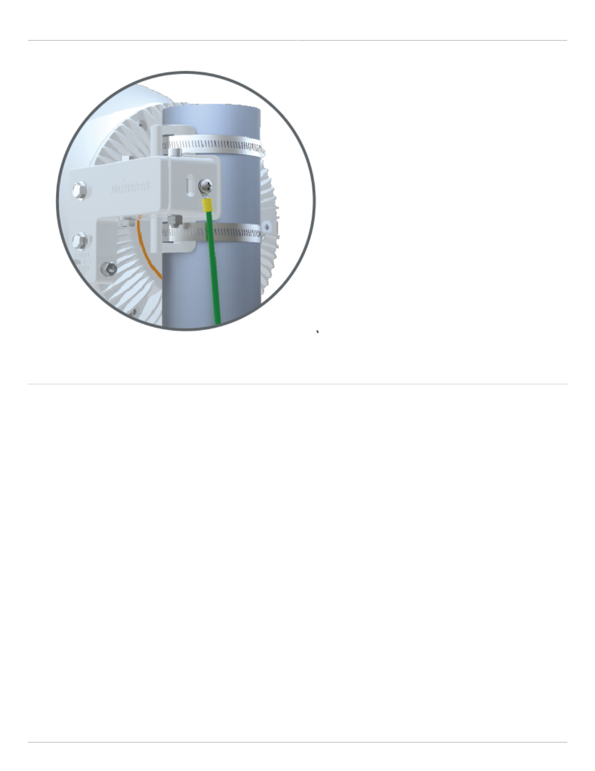
Attach a 6 mm2 (10 AWG) ground wire with a maximum length of 1 m (3.3 feet) between the mounting bracket1.
of the B24 and a suitable grounding location on the tower or structure. The provided grounding screw is M5 x
6mm with 0.8 thread.
Mimosa Backhaul and B24 Help Content
Mimosa Backhaul Mounting & Grounding
Copyright © 2018 Mimosa Page Page 3
Related
B24 Specifications - See specification sheet section entitled, "Physical" for additional mounting hardware details.
Hardware & Materials - Details about what materials are used in each provided part.
Mimosa Backhaul and B24 Help Content
Mimosa Backhaul Mounting & Grounding
Copyright © 2018 Mimosa Page Page 4
Installation, Mounting and Alignment
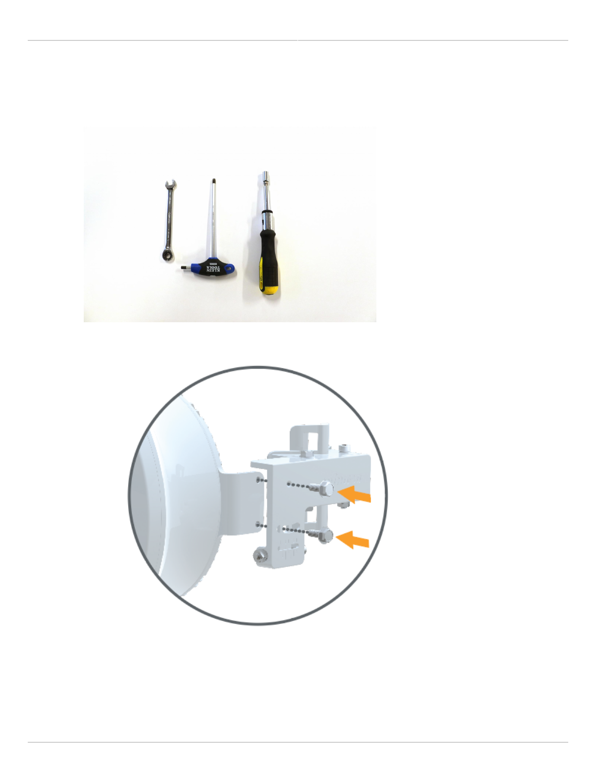
You will need a 10mm wrench, a #5 hex wrench/allen wrench, and a 5/16 nut driver to mount and align the1.
B24.
Take the mounting bracket and attach it to the B24 using the two provided screws. Use your 10mm wrench2.
to tighten the screws down. When you’re ready to adjust elevation, these two screws will need to be
loosened up.
Add both hose clamps to the B24 mount when you’re ready to mount to a pole, j-mount, etc.3.
Once on the pole, tighten down your hose clamps most of the way so that they hold the radio up on the pole.4.
Mimosa Backhaul and B24 Help Content
Mimosa Backhaul Mounting & Grounding
Copyright © 2018 Mimosa Page Page 5
Before tightening your hose clamps down all the way, go ahead and point your B24 toward the other end of5.
the link (coarse alignment). Once you have your radios pointed, go ahead and tighten down the hose clamps.
If you have planned this link out in the Mimosa Design Tool, you will know the -+ degree of the elevation. Go6.
ahead and set your mount to around the correct angle. Keep in mind that each tick mark for elevation is 5
degrees.
Power up the B24 radio so that you can connect to the radio GUI through 2.4GHz Wi-Fi or Ethernet. Once the7.
radios are powered up, you should be able to tell if the radios are linked up or not by looking at the LED light
on the back. If you have a blue flashing light, your link is connected.
Regardless if your link is connected or not, log into the radio and access the radio GUI. On the Dashboard8.
page, you will see the Signal Meter. If connected, you’ll have a signal level listed. Please make sure you are
only adjusting one radio at a time. Also make sure you are not adjusting azimuth and elevation at the same
time. You want to complete one before starting the other.
Now that the radio is powered up, and you’re logged into the radio, you can start the fine adjustment9.
process. Loosen up the hex head screw labeled “AZ LOCK” using your #5 hex wrench and your 10mm
wrench. Failure to loosen this screw will prevent you from adjusting the horizontal/azimuth on your B24
mount.
Now take your hex wrench and insert it into the hex screw labeled “FINE AZ”. Turning clockwise will move10.
your radio to the left, while turning counter-clockwise will move your radio to the right. Pick a direction and
start turning. Watch the signal meter to see if your signal is getting better or worse.
Mimosa Backhaul and B24 Help Content
Mimosa Backhaul Mounting & Grounding
Copyright © 2018 Mimosa Page Page 6
Even if your signal is getting better or
worse, continue turning for a few more turns to determine if you’re connected to a side lobe or not. If you are
the signal will get worse and then much, much better.
Once you have adjusted left and right, move back to where you had the best signal.11.
To adjust elevation, make sure to loosen the two 10mm bolts labeled “ELE LOCK”. If you recall, these were12.
the two bolts used to attach the mount to the B24.
Take your hex wrench and insert it into the hex screw labeled “ELE”. Turning clockwise will reduce the13.
elevation of your radio, while turning counter-clockwise will increase the elevation of your radio. Pick a
direction and start turning. Watch the signal meter to see if your signal is getting better or worse. Even if
your signal is getting better or worse, continue turning for a few more turns to determine if you’re connected
to a side lobe or not. If you are the signal will get worse and then much, much better.
Once you have adjusted left and right, move back to where you had the best signal.14.
Now that you have adjusted one end of the link, follow the same steps to align the other end of the link.15.
Once both radios have been aligned, go ahead and gently tighten the “AZ LOCK” screw and the “ELE LOCK”16.
screws. Once these are tightened down, and you’ve confirmed your signal levels, you will have completed
installation and alignment of your radio link.

Mimosa Backhaul and B24 Help Content
Mimosa Backhaul Overview
Copyright © 2018 Mimosa Page Page 7
General
Product Applicability: B5, B5c, B5-Lite, C5c PTP, B11, B24
FCC Compliance
This equipment has been tested and found to comply with the limits for a Class A digital device, pursuant
This equipment has been tested and found to comply with the limits for a Class A digital device, pursuant
to part 15 of the FCC Rules. These limits are designed to provide reasonable protection against harmful
to part 15 of the FCC Rules. These limits are designed to provide reasonable protection against harmful
interference when the equipment is operated in a commercial environment. This equipment generates,
interference when the equipment is operated in a commercial environment. This equipment generates,
uses, and can radiate radio frequency energy and, if not installed and used in accordance with the
uses, and can radiate radio frequency energy and, if not installed and used in accordance with the
instruction manual, may cause harmful interference to radio communications. Operation of this equipment
instruction manual, may cause harmful interference to radio communications. Operation of this equipment
in a residential area is likely to cause harmful interference in which case the user will be required to
in a residential area is likely to cause harmful interference in which case the user will be required to
correct the interference at his own expense.
correct the interference at his own expense.
This device complies with part 15 of the FCC Rules. Operation is subject to the following two conditions:
(1) This device may not cause harmful interference; and
(2) this device must accept any interference received, including interference that may cause undesired operation.
Note that user changes or modifications not expressly approved by the party responsible for compliance could void
the user's authority to operate the equipment.
RF Exposure Warning
The radiated output power of this device is below the FCC radio frequency exposure limits. Nevertheless, the device
should be used in such a manner that the potential for human contact during the normal operation is minimized. In
order to avoid the possibility of exceeding the FCC radio frequency exposure limit, human proximity to the access
point should be more than 20 cm.
Industry Canada Compliance
This device complies with Industry Canada’s license-exempt RSSs. Operation is subject to the following two
conditions:
(1) This device may not cause interference; and
(2) This device must accept any interference, including interference that may cause undesired operation of the
device.
Le présent appareil est conforme aux CNR d'ISED applicables aux appareils radio exempts de licence.
L'exploitation est autorisée aux deux conditions suivantes:
(1) l'appareil ne doit pas produire de brouillage, et

Mimosa Backhaul and B24 Help Content
Mimosa Backhaul Overview
Copyright © 2018 Mimosa Page Page 8
(2) l'utilisateur de l'appareil doit accepter tout brouillage radioélectrique subi, même si le brouillage est susceptible
d'en compromettre le fonctionnement.
Follow all safety precautions as dictated by your local regulator in installation.

Mimosa Backhaul and B24 Help Content
Mimosa Backhaul Overview
Copyright © 2018 Mimosa Page Page 9
Accessing the Graphical User Interface
Accessing the graphical user interface (GUI) requires that the radio first be connected to power. The Power over
Ethernet (PoE) connection process describes the steps to do this. Note that the GUI will be available approximately
one minute after applying power.
The GUI can be accessed in three ways to facilitate set-up and management.
Locally through the built-in 2.4 GHz wireless management network (B5/B5c and B11 Only)1.
Through the local Ethernet interface (LAN), or the fiber (SFP) if applicable2.
Remotely through the Point to Point wireless link3.
Via 2.4 GHz Management Network
On any device with 2.4 GHz 802.11n capability, go to the wireless network listing and connect to the Local Network
Management wireless network (SSID): "mimosaMXXX". The default passphrase for the 2.4 GHz connection is
"mimosanetworks". Once connected, type 192.168.25.1 into your browser. Please note that both the Local Network
Management SSID and passphrase are configurable by the user, so their values could be different from the default
values.
Via Ethernet interface or in-band over the Point to Point link
By default, the device IP address is 192.168.1.20 and can be accessed via the Ethernet port using this IP address in
any standard Web browser. To access the device via a locally connected computer initially (on the same LAN or
directly to the Ethernet port), the computer’s IP address must be on the same subnet as the above address. Once
you have modified the IP address (static or is DHCP) of the device for remote management purposes (in-band over
wireless or over the Ethernet interface), the new specified IP address must be used to access the device. This is
important to do in order to avoid IP address conflicts with other devices on the network. Current IP addresses of
different Mimosa devices on the network can be identified using terminal-based discovery. It is highly recommended
to change the default password to a unique and secured password.
Mimosa Backhaul and B24 Help Content
Mimosa Backhaul Overview
Copyright © 2018 Mimosa Page Page 10
Logging In
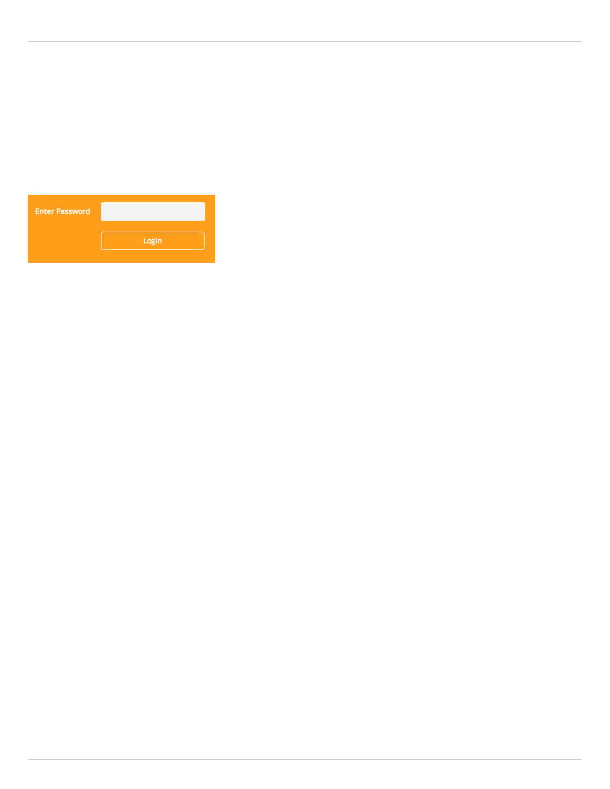
After connecting via one of the three access methods, the GUI will prompt you to log-in with a password. The
default password is "mimosa", and should be changed immediately after login to protect your network since it gives
the user read / write privileges. The password can be changed within the Preferences > General > Set Password
panel of the GUI.
Mimosa Backhaul and B24 Help Content
Mimosa Backhaul Overview
Copyright © 2018 Mimosa Page Page 11
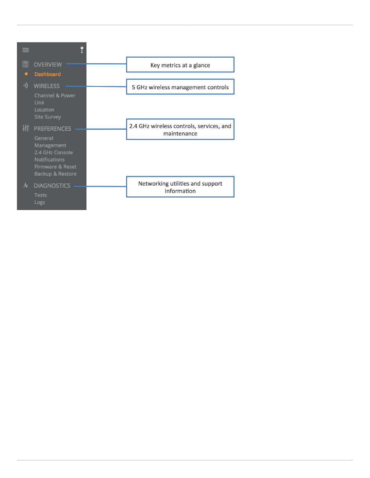
User Interface Overview
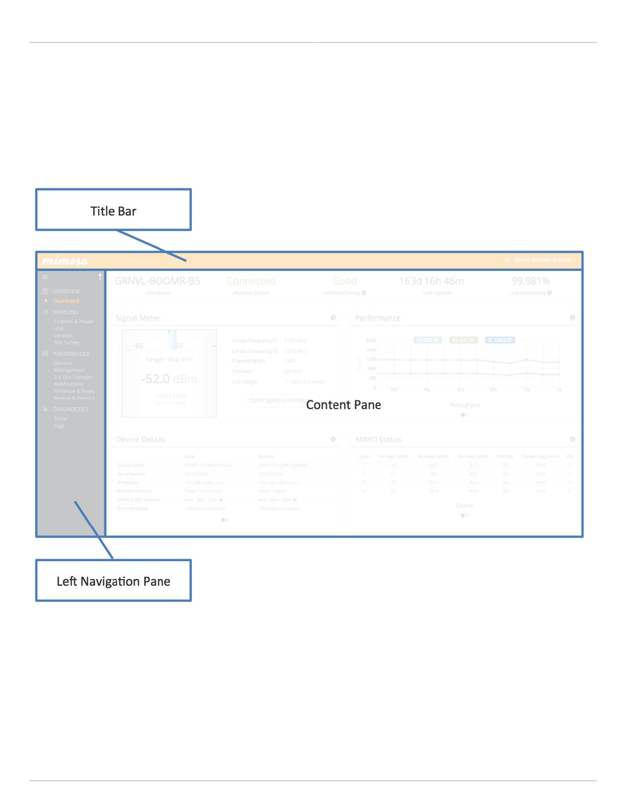
When you first log in, you’ll notice that there is a title bar with the device name shown in the top-right corner, a
navigation pane on the left, and a large content pane on the right. The default page shown in the content pane is
the Dashboard, which shows a summary of overall performance at a glance, and highlights both radio and link
parameters that affect link health.
On the left navigation pane, there are four prominent sections: Overview, Wireless, Preferences, and Diagnostics.
Each of these sections contains one or more links to pages containing task-related data, controls, and tools used to
administer the radio…and you can return the Dashboard at any time by clicking on the Dashboard link in the
Overview section.
The pin in the top corner of the left navigation pane allows you to "pin" open the navigation menu for easier access.
Else, the menu contracts to provide more workspace within the GUI. Note that the 2.4 GHz Console menu item is not
present on the B5-Lite.
Mimosa Backhaul and B24 Help Content
Mimosa Backhaul Overview
Copyright © 2018 Mimosa Page Page 12
Mimosa Backhaul and B24 Help Content
Mimosa Backhaul Dashboard
Copyright © 2018 Mimosa Page Page 13
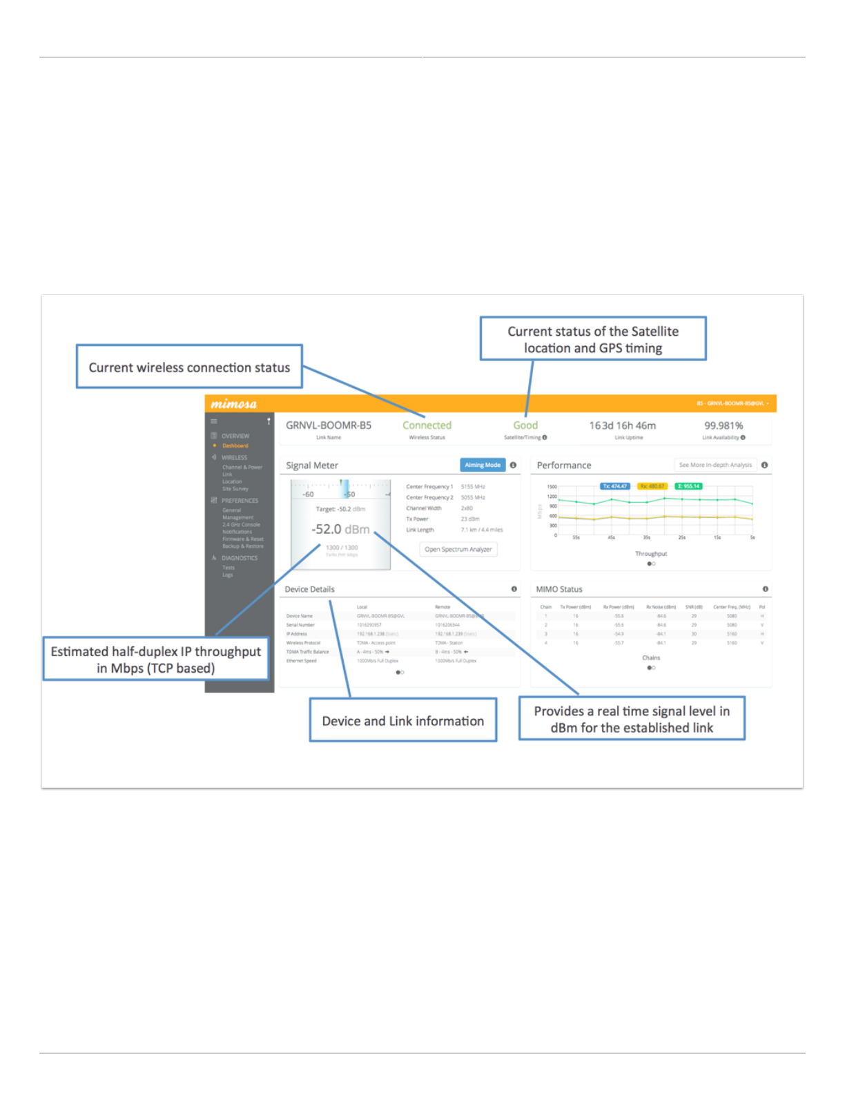
The Dashboard
The Dashboard contains several panels used to group related items. The status panel at the top of the page shows
the link SSID, the link status, GPS signal quality*, Link Uptime since association, and Link Availability since the last
reboot. Two of the values on this panel contain an information icon that shows more information when you click or
hover over it with your mouse cursor. On other panels, detailed help text can be found by clicking on the
information icon in the upper right hand corner.
* Applies to B5/B5c, B11, and B24 only; does not apply to B5-Lite or C5c PTP.

Mimosa Backhaul and B24 Help Content
Mimosa Backhaul Dashboard
Copyright © 2018 Mimosa Page Page 14
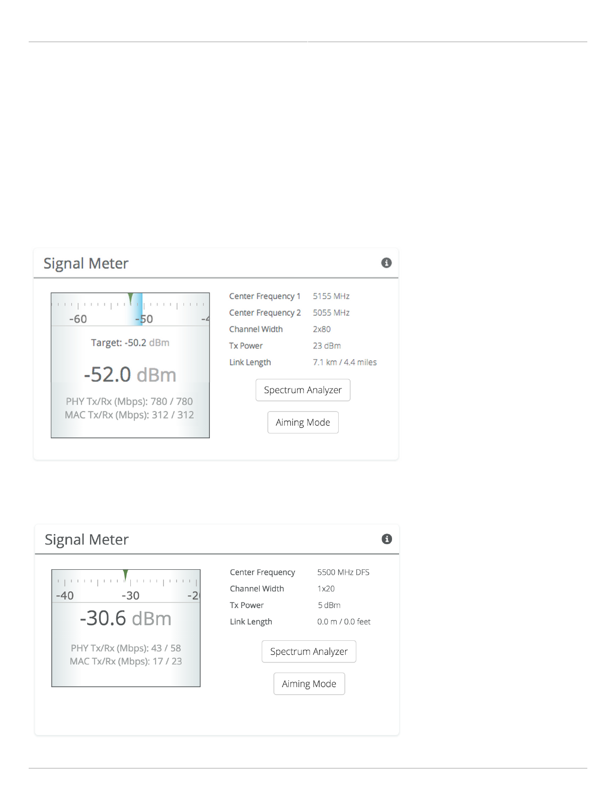
Reading the Signal Meter
Connected Link
Received signal strength is shown in large text in the center of the control, and as a green indicator in the top dial.
The blue shaded bar and text immediately below the dial represent target signal strength based on distance and
other information exchanged between radios. The objective is to align the green indicator with the blue bar as a
guideline during antenna aiming.
The resulting half-duplex PHY rates shown at the bottom of the Signal Meter control are correlated with the MCS,
and represent raw data across the link without protocol overhead. The Max Throughput values include TDMA
window size and MAC layer efficiency.
The following settings and values that affect link health are listed for reference:
B5/B5c
Channel 1 Center Frequency - True center of the first frequency range (no offset).
●
Channel 2 Center Frequency - True center of the second frequency range (no offset).
●
Channel Width - Number of channels used (1 or 2), and the width of each channel (20, 40 or 80 MHz).
●
Tx Power - Total transmit power level (dBm).
●
Link Length - Distance between local and remote radios (when connected).
●
B5-Lite/C5c PTP
Center Frequency - True center of the frequency range (no offset).
●
Channel Width - The width of the channel (20, 40 or 80 MHz).
●
Tx Power - Total transmit power level (dBm).
●
Link Length - Distance between local and remote radios (when connected).
●
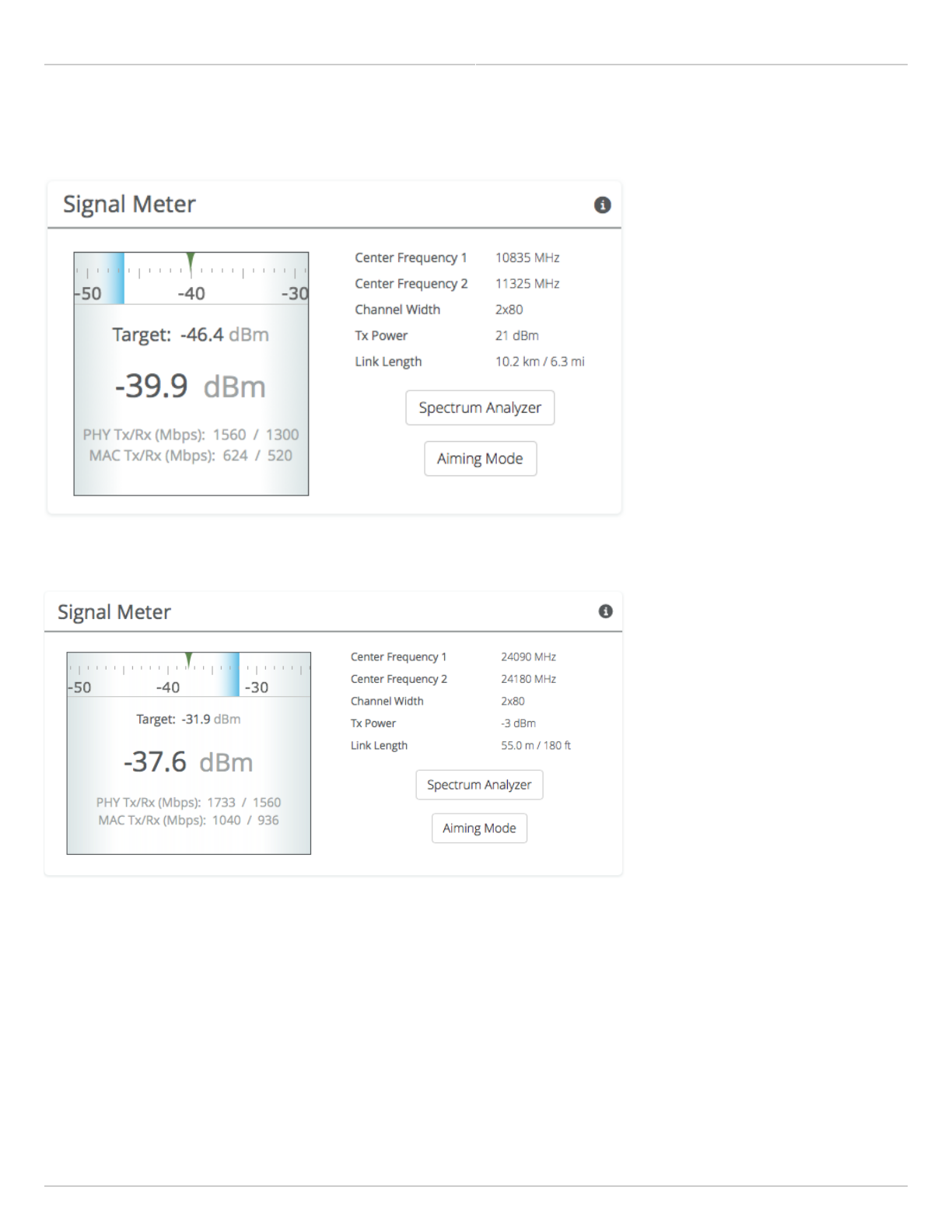
B11
Center Frequency 1 - True center of the first frequency range (no offset).
●
Center Frequency 2 - True center of the second frequency range (no offset).
●
Channel Width - Number of channels used (1 or 2), and the width of each channel (20, 40 or 80 MHz).
●
Tx Power - Total transmit power level (dBm).
●
Link Length - Distance between local and remote radios (when connected).
●
B24
Center Frequency 1 - True center of the first frequency range (no offset).
●
Center Frequency 2 - True center of the second frequency range (no offset).
●
Channel Width - Number of channels used (1 or 2), and the width of each channel (20, 40 or 80 MHz).
●
Tx Power - Total transmit power level (dBm).
●
Link Length - Distance between local and remote radios (when connected).
●
Click the Spectrum Analyzer button to access the Spectrum Analyzer, which can also be found on the Channel &
Power page. This will not disturb the link.
Mimosa Backhaul and B24 Help Content
Mimosa Backhaul Dashboard
Copyright © 2018 Mimosa Page Page 15
When a link is not associated, the signal strength and PHY rates are replaced by an indicator of "Disconnected".
Once associated, click the Aiming Mode button on the Dashboard to open a new window that refreshes once per
second for a 5-minute period. The Aim Heading indicates the direction in which the front of the device should be
pointed based exchange of coordinates. The green arrow and blue shaded region on the dial indicator represent
current and target signal levels, respectively. Note that the dial indicator does not represent azimuth. Azimuth may
need to be adjusted in either direction to meet the target.
B5/B5c Signal Meter
B5-Lite Signal Meter
Mimosa Backhaul and B24 Help Content
Mimosa Backhaul Dashboard
Copyright © 2018 Mimosa Page Page 16
B11 Signal Meter
B24 Signal Meter
Mimosa Backhaul and B24 Help Content
Mimosa Backhaul Dashboard
Copyright © 2018 Mimosa Page Page 17
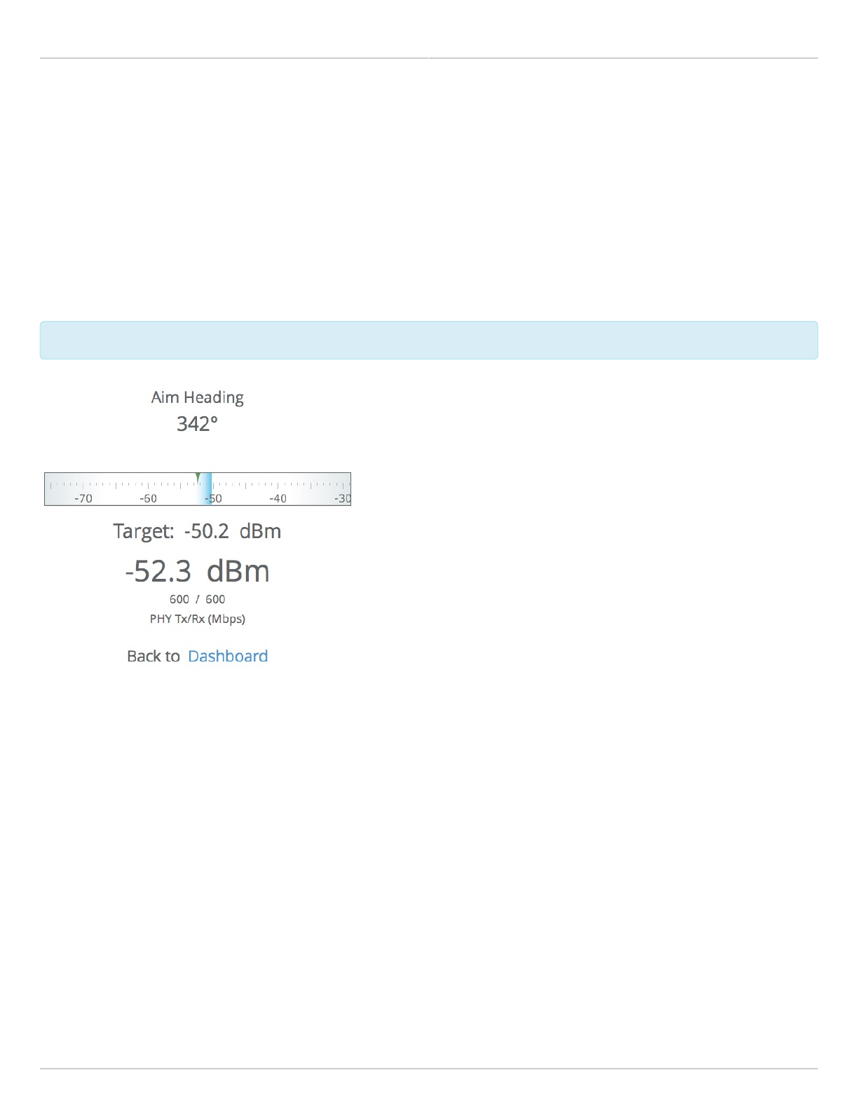
Antenna Aiming Mode
Product Availibility: B5/B5c, B11, B24
Once associated, click the Aiming Mode button on the Dashboard to open a new window that refreshes once per
second for a 5-minute period. The Aim Heading indicates the direction in which the front of the device should be
pointed based exchange of coordinates. The green arrow and blue shaded region on the dial indicator represent
current and target signal levels, respectively. Note that the dial indicator does not represent azimuth. Azimuth may
need to be adjusted in either direction to meet the target.
Note that the target signal level will be incorrect if the antenna gain value is inaccurate (B5c and B11).
Note that the target signal level will be incorrect if the antenna gain value is inaccurate (B5c and B11).
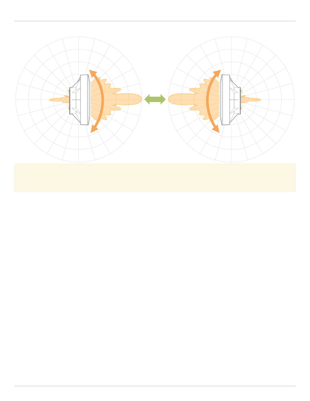
Antenna Aiming Procedure
While viewing the Aiming Mode screen, move the local antenna on one axis at a time (first azimuth and then1.
elevation) in 6mm (1/4 inch) increments.
Wait 2-3 seconds for the signal to settle after each movement. Signal strength may increase or decrease after2.
each movement. Increases in signal strength will move the green arrow and blue shaded region closer
together. Decreases in signal strength will move them farther apart. The point of maximum signal strength
indicates optimal antenna alignment for each axis.
Repeat the steps 1 and 2 above on the remote antenna. The signal strength should match the outputs from3.
the Mimosa Design application. If not, please consult the Low Rx Power troubleshooting guide.
Mimosa Backhaul and B24 Help Content
Mimosa Backhaul Dashboard
Copyright © 2018 Mimosa Page Page 18
Tip: Use a pen (or a piece of tape) to place an alignment mark on both the antenna mount and the
Tip: Use a pen (or a piece of tape) to place an alignment mark on both the antenna mount and the
mounting pole. The gap between the marks will serve as a visual aid to show how far the antenna has
mounting pole. The gap between the marks will serve as a visual aid to show how far the antenna has
turned in either direction.
turned in either direction.
Mimosa Backhaul and B24 Help Content
Mimosa Backhaul Dashboard
Copyright © 2018 Mimosa Page Page 19
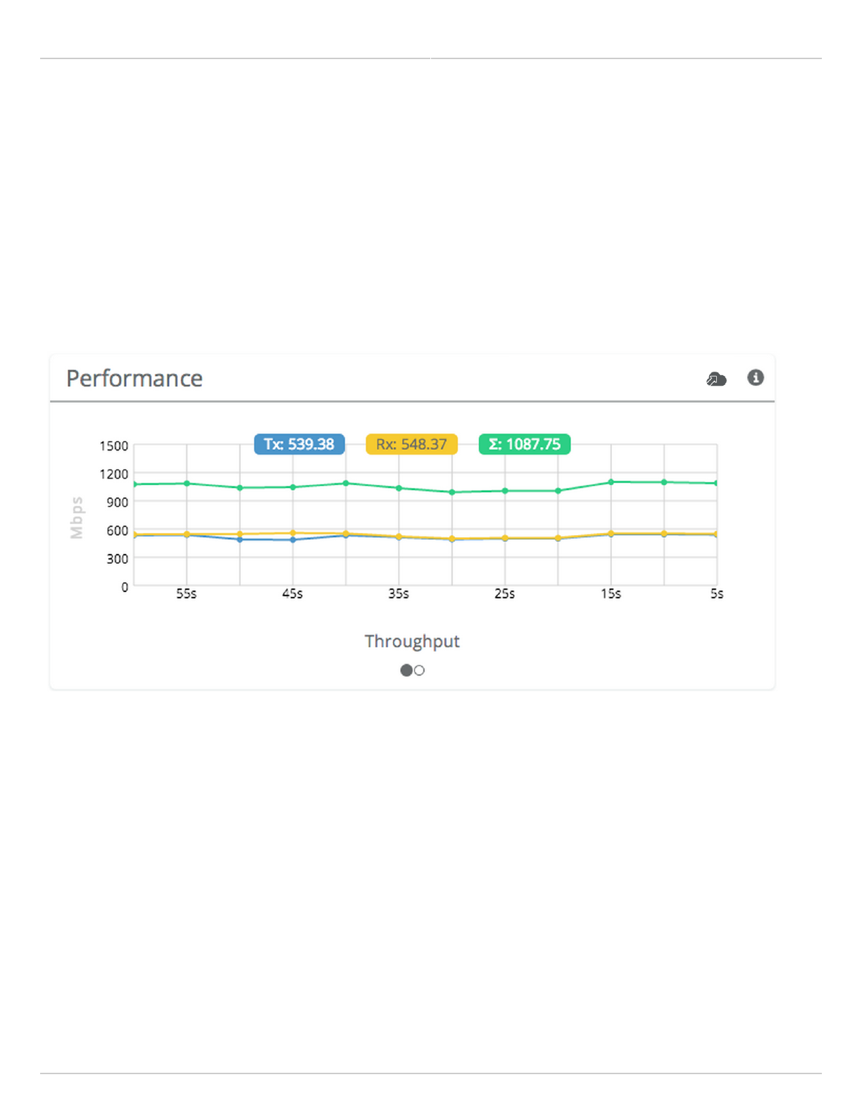
Reading the Performance Charts
IP Throughput and Packet Error Rate (PER) are charted over 60 seconds in 5-second intervals. The newest data
shows up on the right and scrolls to the left over time. You can toggle between the charts by clicking on the
navigation circles at the bottom of the panel. If enabled, click on the cloud icon to view historical data within the
Manage application.
The IP Throughput graph plots three lines representing transmit, receive, and aggregate (summed) throughputs at
the datagram (or packet) layer excluding any protocol or encapsulation overhead. The results here may differ from
those measured using speed test tools, due to protocol overhead and encapsulation. Note that internal Bandwidth
test results are excluded.
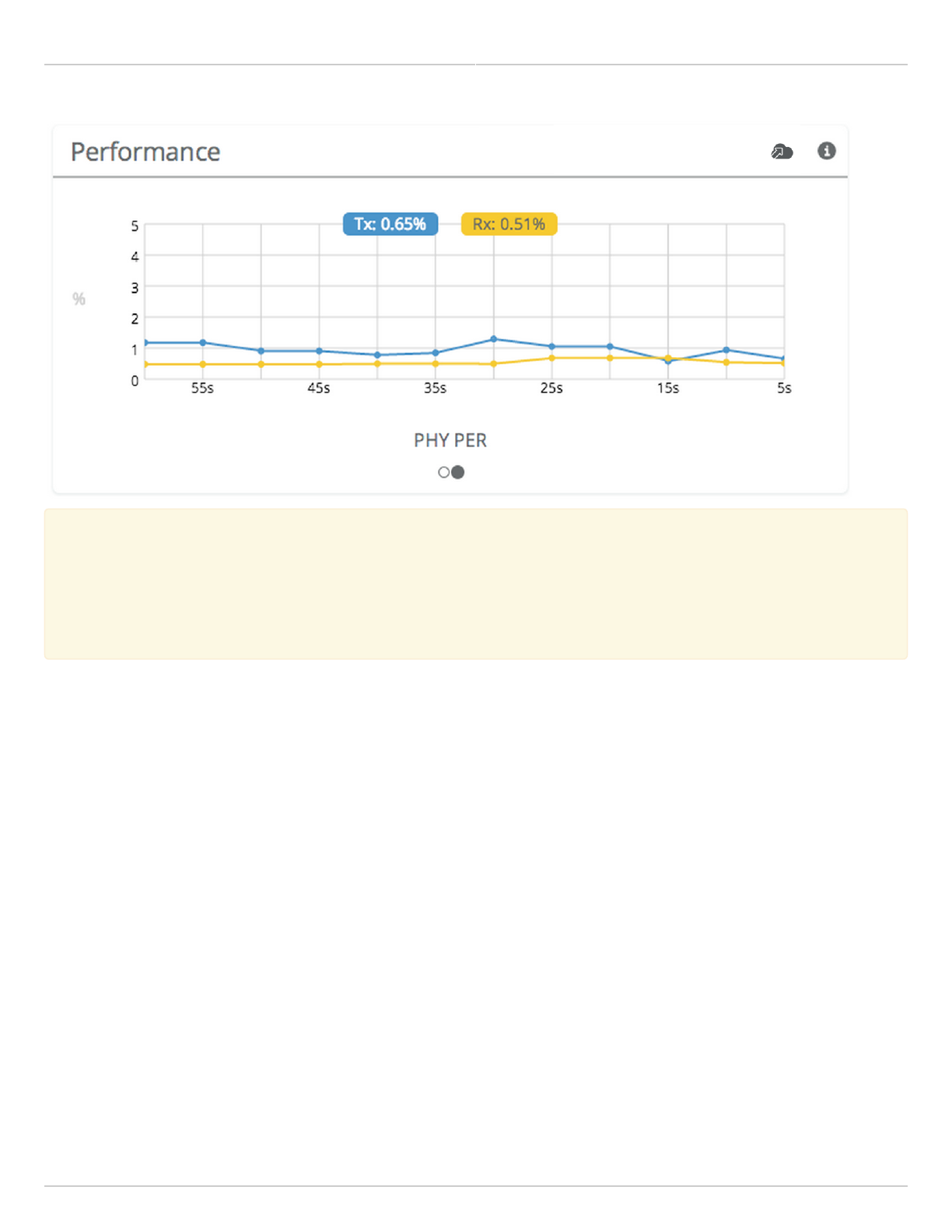
The Packet Error Rate (PER) is the number of packets with errors divided by the total number of packets sent within
a 5-second period. Ideally, this value should be below 2%, while higher values indicate the presence of interference.
Tx PER is an indication that the local radio did not receive an ACK from the remote radio, so is forced to retransmit
the same information again. Rx PER is a value sent from the remote radio to the local radio in management frames.
Mimosa Backhaul and B24 Help Content
Mimosa Backhaul Dashboard
Copyright © 2018 Mimosa Page Page 20
Note: PER will be higher upon initial association, and will usually settle within 30-60 seconds. This is
Note: PER will be higher upon initial association, and will usually settle within 30-60 seconds. This is
because association requires that the radios “listen” more carefully for their link partner until they are
because association requires that the radios “listen” more carefully for their link partner until they are
linked, and this listening period is subject to more interference until Automatic Gain Control (AGC) and
linked, and this listening period is subject to more interference until Automatic Gain Control (AGC) and
Rate Adaptation (RA) adjust parameters to accommodate the conditions. PER values are exchanged
Rate Adaptation (RA) adjust parameters to accommodate the conditions. PER values are exchanged
between radios asynchronously, so the values may not match exactly when referencing both radios at the
between radios asynchronously, so the values may not match exactly when referencing both radios at the
same time.
same time.

Mimosa Backhaul and B24 Help Content
Mimosa Backhaul Dashboard
Copyright © 2018 Mimosa Page Page 21
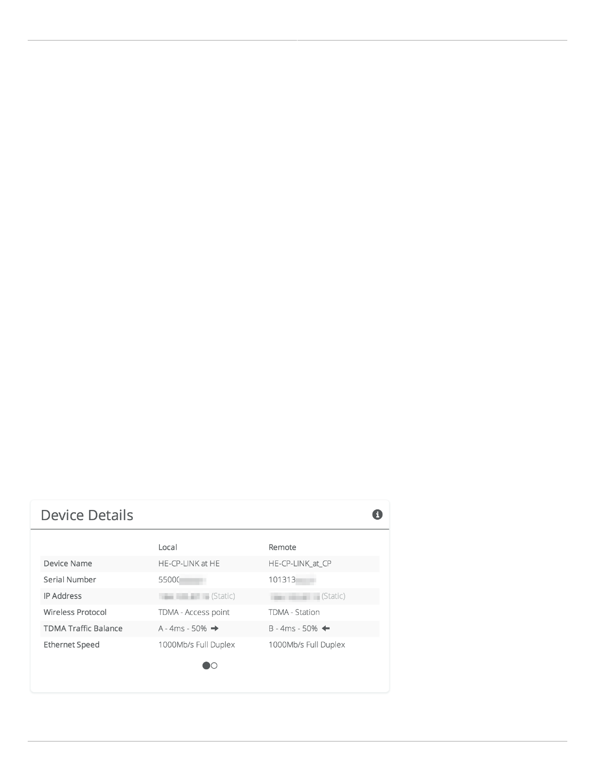
Reading Device Details
The Device Details panel shows two summary tables for the local and remote device configurations and their status.
Click on the navigation circles at the bottom of the panel to toggle between the two tables.
The table shows the following for both Local and Remote devices:
B5/B5c
Device Name - The friendly name given to each device. (Set in Preferences > General > Naming)
●
Serial Number - The unique identifier for the device assigned at the factory.
●
IP Address - The IP address of each device and how it was assigned. (Set in Preferences > Management)
●
Wireless Protocol - The MAC level protocol. (Set in Wireless > Link > MAC Configuration)
●
TDMA Traffic Balance - Identifies the "gender" of the radio, the duration for each TDMA time slot, and ratio of
●
bandwidth allocated for transmission. (Set in Wireless > Link > MAC Configuration)
Ethernet Speed - Data rate and duplex mode of the wired Ethernet interface.
●
Firmware - The latest firmware version applied to each device. (Set in Preferences > Update & Reboot)
●
Internal Temp - Temperature inside the device case (operating range: -40 °C to +60 °C).
●
2.4 GHz MAC - The unique identifier for the 2.4 GHz radio.
●
5 GHz MAC - The unique identifier for the 5 GHz radio.
●
Ethernet MAC - The unique identifier for the physical Ethernet interface.
●
Last Reboot - The date and time at which each device last rebooted.
●
B5-Lite/C5c PTP
Device Name - The friendly name given to each device. (Set in Preferences > General > Naming)
●
Serial Number - The unique identifier for the device assigned at the factory.
●
IP Address - The IP address of each device and how it was assigned. (Set in Preferences > Management)
●
Wireless Protocol - The MAC level protocol. (Set in Wireless > Link > MAC Configuration)
●
TDMA Traffic Balance - Identifies the "gender" of the radio, the duration for each TDMA time slot, and ratio of
●
bandwidth allocated for transmission. (Set in Wireless > Link > MAC Configuration)
Ethernet Speed - Data rate and duplex mode of the wired Ethernet interface.
●
Firmware - The latest firmware version applied to each device. (Set in Preferences > Update & Reboot)
●
CPU Temp - Temperature on the device CPU (operating range: -40 °C to +110 °C).
●
5 GHz MAC - The unique identifier for the 5 GHz radio.
●
Ethernet MAC - The unique identifier for the physical Ethernet interface.
●
Last Reboot - The date and time at which each device last rebooted.
●
B11
Device Name - The friendly name given to each device. (Set in Preferences > General > Naming)
●
Serial Number - The unique identifier for the device assigned at the factory.
●
IP Address - The IP address of each device and how it was assigned. (Set in Preferences > Management)
●
Wireless Protocol - The MAC level protocol. (Set in Wireless > Link > MAC Configuration)
●
TDMA Traffic Balance - Identifies the "gender" of the radio, the duration for each TDMA time slot, and ratio of
●
bandwidth allocated for transmission. (Set in Wireless > Link > MAC Configuration)
Ethernet Speed - Shows data rate and duplex mode if the link is up else "Link Down". Shows "Off" if the
●
interface is not enabled.
Mimosa Backhaul and B24 Help Content
Mimosa Backhaul Dashboard
Copyright © 2018 Mimosa Page Page 22
SFP Speed - Shows data rate and duplex mode if the link is up else "Link Down". Shows "Off" if the interface is
●
not enabled.
Network Interface - Shows the interface enabled; "Ethernet" or "SFP".
●
Firmware - The latest firmware version applied to each device (Set in Preferences > Update & Reboot).
●
Internal Temp - Temperature inside the device casing (operating range: -40 °C to +60 °C).
●
11 GHz MAC - The unique identifier for the 10/11 GHz radio.
●
2.4 GHz MAC - The unique identifier for the 2.4 GHz radio.
●
Ethernet MAC - The unique identifier for the physical Ethernet interface.
●
SFP MAC - The unique identifier for the physical SFP interface.
●
Last Reboot - The date and time at which each device last rebooted.
●
B24
Device Name - The friendly name given to each device. (Set in Preferences > General > Naming)
●
Serial Number - The unique identifier for the device assigned at the factory.
●
IP Address - The IP address of each device and how it was assigned. (Set in Preferences > Management)
●
Wireless Protocol - The MAC level protocol. (Set in Wireless > Link > MAC Configuration)
●
TDMA Traffic Balance - Identifies the "gender" of the radio, the duration for each TDMA time slot, and ratio of
●
bandwidth allocated for transmission. (Set in Wireless > Link > MAC Configuration)
Ethernet (RJ45) Status - Shows data rate and duplex mode if the link is up else "Link Down". Shows "Off" if the
●
interface is not enabled.
Fiber (SFP) Status - Shows data rate and duplex mode if the link is up else "Link Down". Shows "Off" if the
●
interface is not enabled.
Network Interface - Shows the interface enabled; "Ethernet (RJ45)", "Fiber (SFP)" or "Failover Ethernet (RJ45)".
●
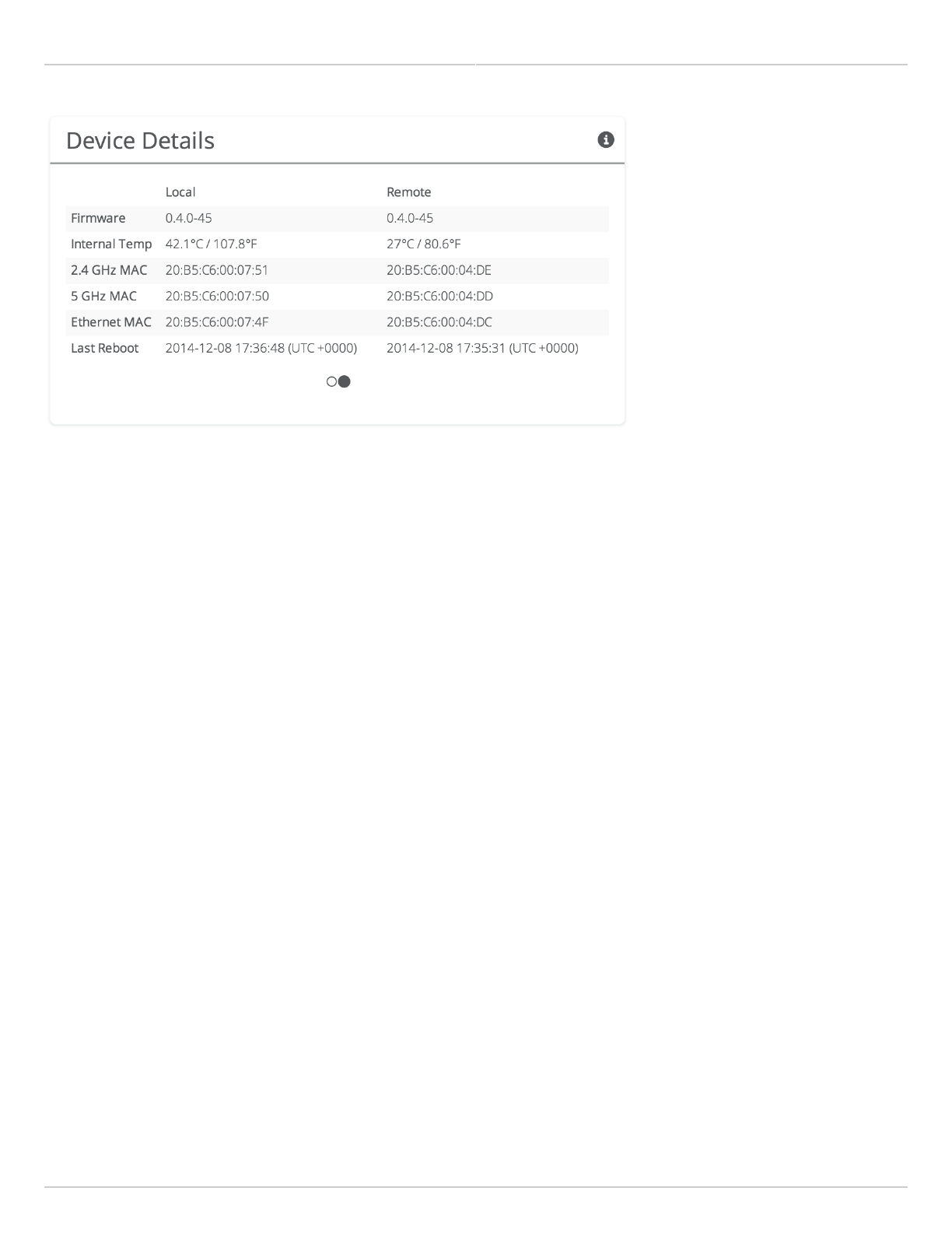
Firmware - The latest firmware version applied to each device (Set in Preferences > Update & Reboot).
●
Internal Temp - Temperature inside the device casing (operating range: -40 °C to +90 °C).
●
2.4 GHz MAC - The unique identifier for the 2.4 GHz radio.
●
24 GHz MAC - The unique identifier for the 24 GHz radio.
●
Ethernet MAC - The unique identifier for the physical Ethernet (RJ45) interface.
●
SFP MAC - The unique identifier for the physical Fiber (SFP) interface.
●
Last Reboot - The date and time at which each device last rebooted.
●
Mimosa Backhaul and B24 Help Content
Mimosa Backhaul Dashboard
Copyright © 2018 Mimosa Page Page 23
Mimosa Backhaul and B24 Help Content
Mimosa Backhaul Dashboard
Copyright © 2018 Mimosa Page Page 24
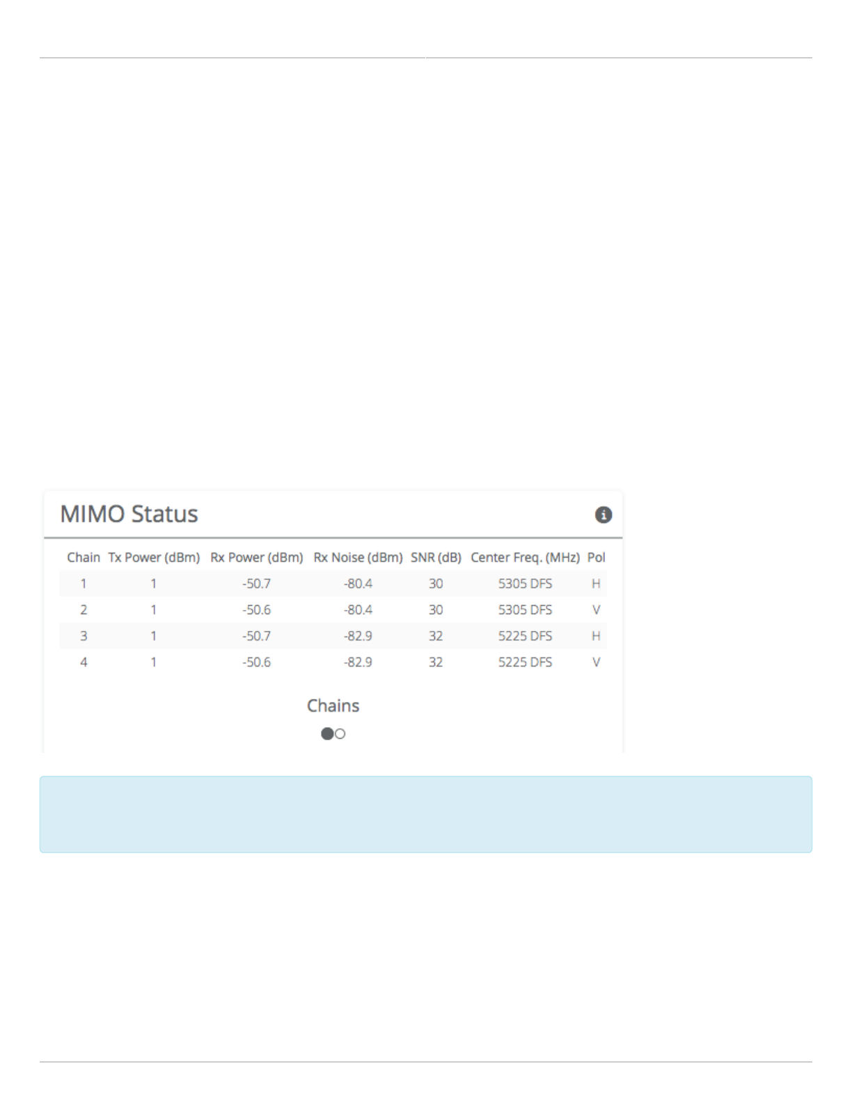
Reading MIMO Status Tables
The MIMO Status panel contains two tables: Chains and Streams. Chains represent the physical medium (RF Tx/Rx
values), while Streams represent data. Chains and Streams are not necessarily correlated one to one because the
Rate Adaptation algorithm may periodically increase or decrease the number of data streams sent over the physical
medium when reacting to interference.
The Chains table describes each chain's power, noise, SNR, frequency and polarization.
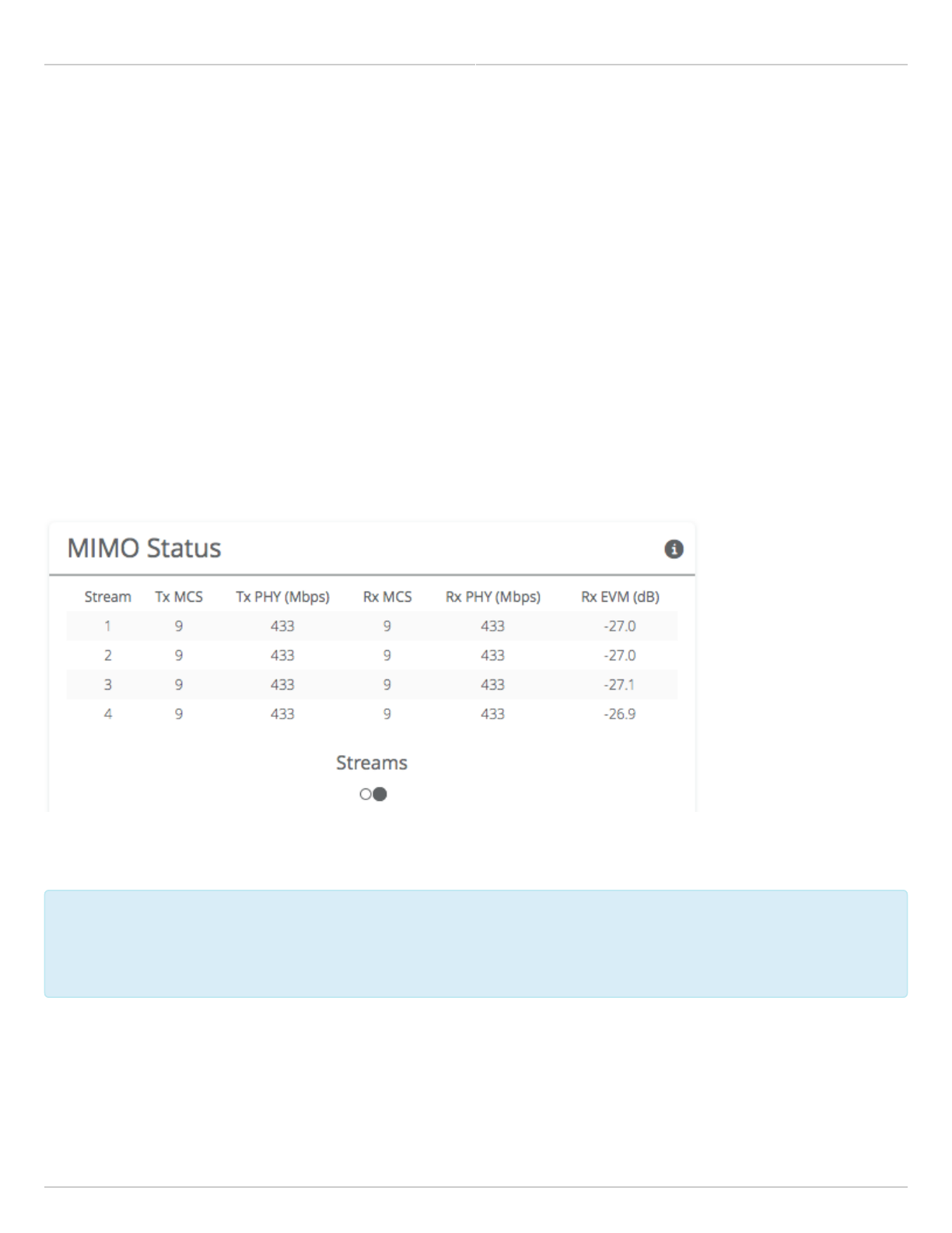
The Streams table describes each stream's MCS index, PHY rates and Rx Error Vector Magnitude (EVM).
Each table can be selected by clicking on the navigation circles at the bottom of the panel.
Chains
The Chains table contains 6 values: Tx Power, Rx Power, Rx Noise, SNR, Center Frequency and Polarization. Each
channel is assigned two chains (horizontal and vertical). If two channels are selected, Channel 1 uses Chains 1 & 2,
while Channel 2 uses Chains 3 & 4.
Tx Power is the amount of power applied to each of the MIMO chains.
Tx Power can be shared evenly (preferred), or unevenly (if necessary), between channels. The Tx power
Tx Power can be shared evenly (preferred), or unevenly (if necessary), between channels. The Tx power
per channel is divided evenly per chain. Example: 4 dBm Tx power on Channel 1 results in 1 dBm each on
per channel is divided evenly per chain. Example: 4 dBm Tx power on Channel 1 results in 1 dBm each on
Chains 1 & 2.
Chains 1 & 2.
Rx Power is the incoming signal level from the remote radio. Larger values are better (e.g. -50 dBm is better than -
60 dBm).
Rx Noise is a combination of the thermal noise floor plus interference detected by the local radio. Smaller values are
better (e.g. -90 dBm is better than -80 dBm). Noise sources can be either in close proximity to the local radio, or
they can be remote transmitters pointed back at the local radio.
Mimosa Backhaul and B24 Help Content
Mimosa Backhaul Dashboard
Copyright © 2018 Mimosa Page Page 25
The signal-to-noise ratio (SNR) is the difference between the Rx Power and Rx Noise, and is a measure of how well
the local receiver can detect signals from the remote transmitter and clearly discern them from noise. Higher
values are better (e.g. 30 dB is better than 10 dB).
If two channels are selected, you may observe that SNR is much lower on one channel than the other. This could be
because the Tx Power is set lower on the remote transmitter, or because of higher interference levels on the
channel. To resolve this, increase Tx Power or change the channel that has lower SNR.
Chains 1 & 3 have horizontal polarization, and Chains 2 & 4 have vertical polarization. Chains with the same
polarization are combined internal to the radio before exiting to the antenna connectors.
Streams
The Streams table contains the Tx MCS index, Tx PHY rate, Rx MCS index, Rx PHY rate, and the Rx EVM for each
stream.
The Tx MCS is an indicator of how well the remote radio can receive data from the local transmitter. The Rx MCS
indicates how well the local radio is receiving data from the remote transmitter.
The Modulation Coding Scheme (MCS) represents how much data can be sent at a time, so directly affects
The Modulation Coding Scheme (MCS) represents how much data can be sent at a time, so directly affects
potential throughput represented by the PHY rate. The higher the MCS index (ranging from 0-9), the more
potential throughput represented by the PHY rate. The higher the MCS index (ranging from 0-9), the more
data that can be sent per transmission. A disadvantages of higher MCS indices is that they require higher
data that can be sent per transmission. A disadvantages of higher MCS indices is that they require higher
SNR since they are more vulnerable to noise.
SNR since they are more vulnerable to noise.
The Error Vector Magnitude (EVM) indicates the difference between the actual and expected amplitude and phase of
an incoming signal. Smaller values are better (e.g. -30 dB is better than -10 dB).
Rate Adaptation dynamically adjusts both the MCS and the number of streams depending on RF conditions. Poor RF
conditions (i.e. interference) causes PER to increase. PER and MCS are inversely correlated meaning that as PER

Mimosa Backhaul and B24 Help Content
Mimosa Backhaul Dashboard
Copyright © 2018 Mimosa Page Page 26
increases, MCS decreases and vice versa.
Single channel mode usually uses 2 streams, but may drop to one stream if RF conditions are poor. Dual channel
mode uses up to 4 streams. You may also see the number of streams change periodically because of tests that
Rate Adaptation performs to optimize performance. This is expected and normal.
Related:
Backhaul FAQ: What SNR is required for each MCS?
Backhaul FAQ: What is the sensitivity for each MCS index?
Backhaul FAQ: What's a good EVM?
Mimosa Backhaul and B24 Help Content
Mimosa Backhaul Channel & Power
Copyright © 2018 Mimosa Page Page 27
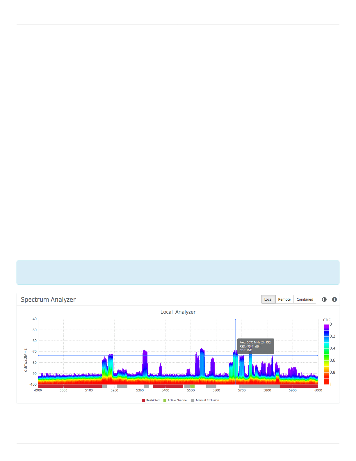
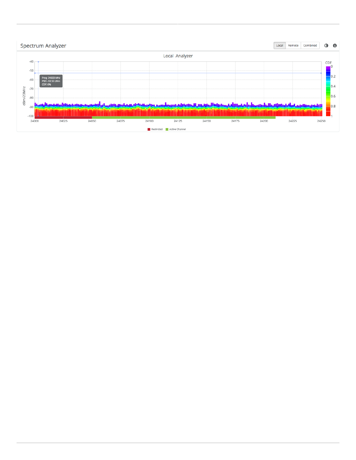
Reading the Spectrum Analyzer
The Spectrum Analyzer actively scans the spectrum in the background to report on interference sources that may
impact link performance.
Click the Local, Remote, or Combined buttons to each radio's spectrum individually or simultaneously. Note that the
remote side data may be as much as 5 minutes behind the local radio. Click on the half circle icon in the upper right
to toggle the graph's background color between black and white.
Channels in use have higher Power Spectral Density (PSD) on the vertical axis, and are shaded in different colors to
represent how often the signals are likely to be on the same frequency at the same amplitude.
The legend to the right of the graph explains the color code for the Cumulative Distribution Function (CDF). The
color red suggests the highest probability (1 = 100%), while purple represents the lowest probability (0 = 0%).
Cross hairs appear on the graph beneath the mouse pointer along with an information box containing the frequency
(channel), PSD, and CDF values.
There are three types of markings, or bars, immediately beneath the graph’s horizontal axis that indicate frequency
ranges that are restricted, manually excluded, or in active use by this link. Note that traffic from the Active Channel
is excluded from the display so that noise can be detected.
Note: Buttons on the upper right of the graph show the spectrum for the local radio, the remote radio or a
Note: Buttons on the upper right of the graph show the spectrum for the local radio, the remote radio or a
combined view.
combined view.
B24 Spectrum Analyzer
Mimosa Backhaul and B24 Help Content
Mimosa Backhaul Channel & Power
Copyright © 2018 Mimosa Page Page 28

Mimosa Backhaul and B24 Help Content
Mimosa Backhaul Channel & Power
Copyright © 2018 Mimosa Page Page 29
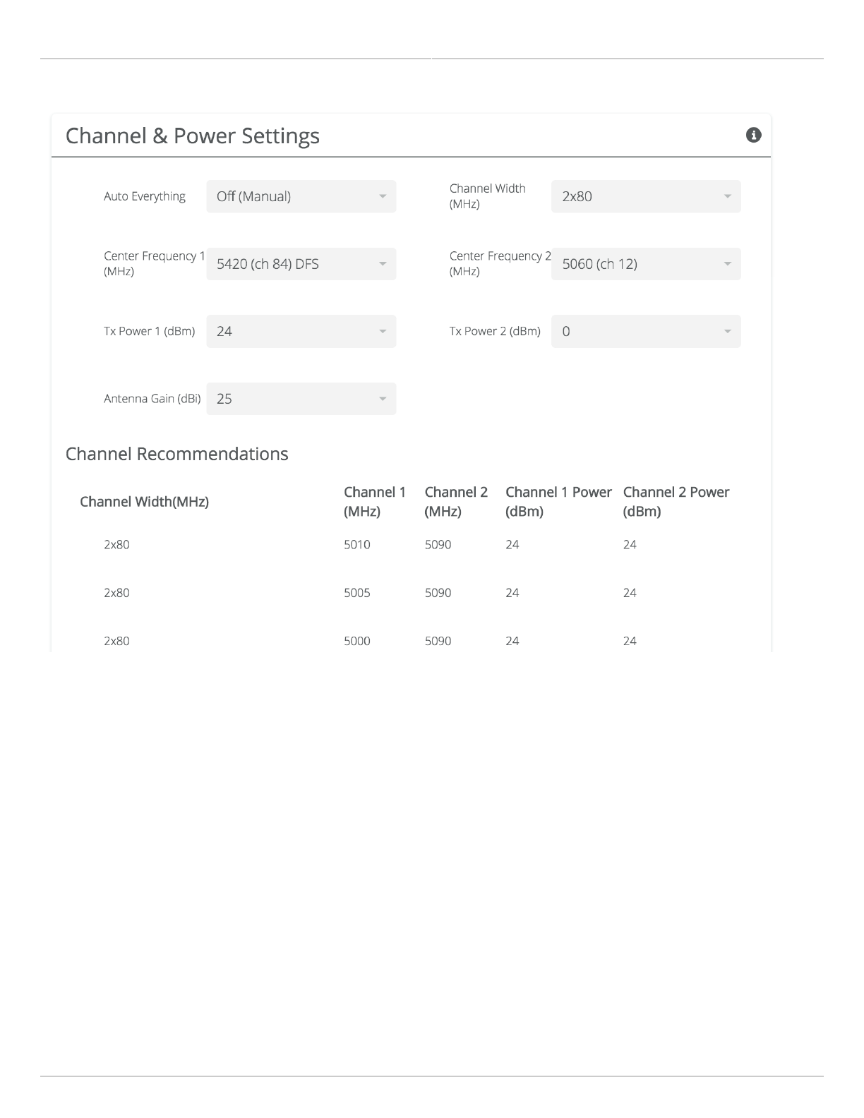
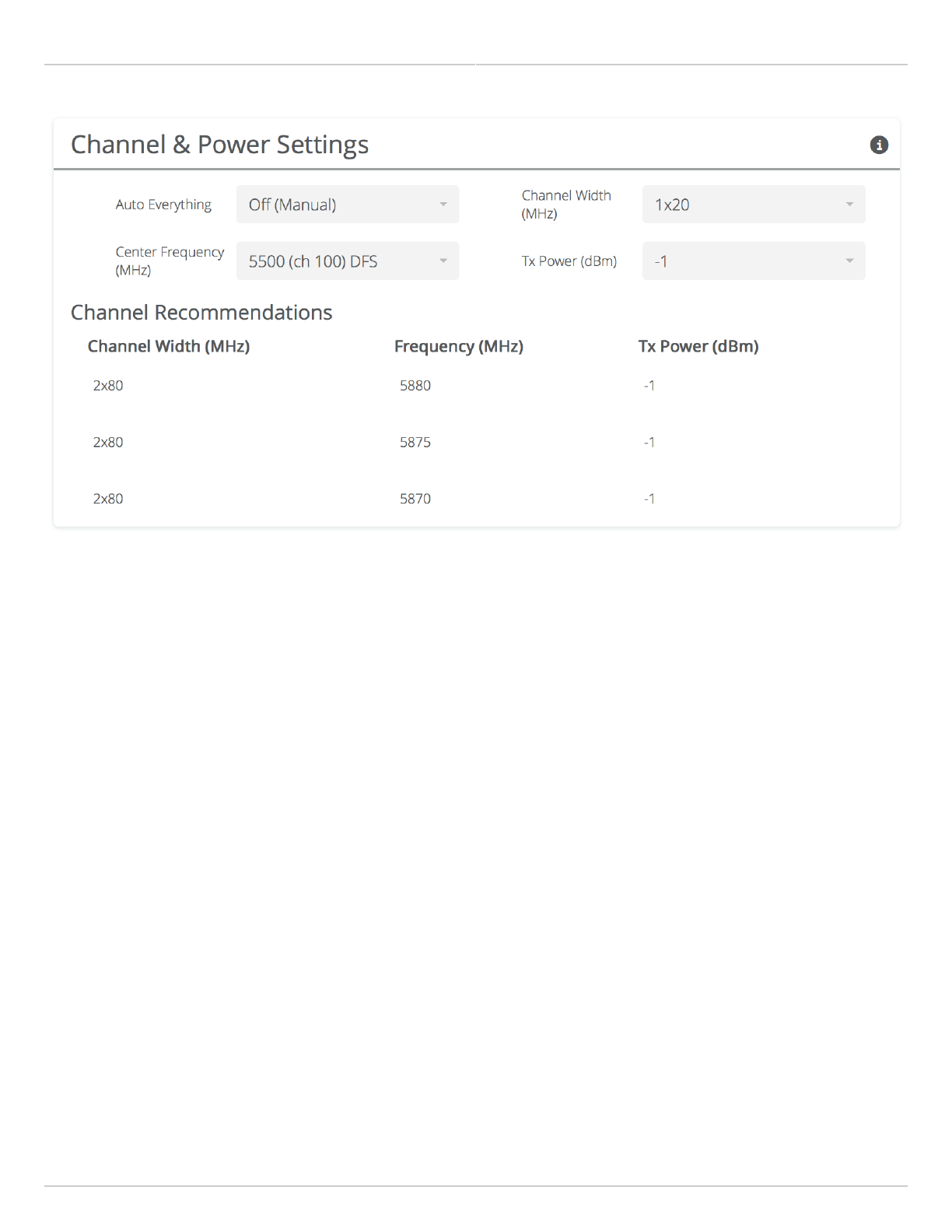
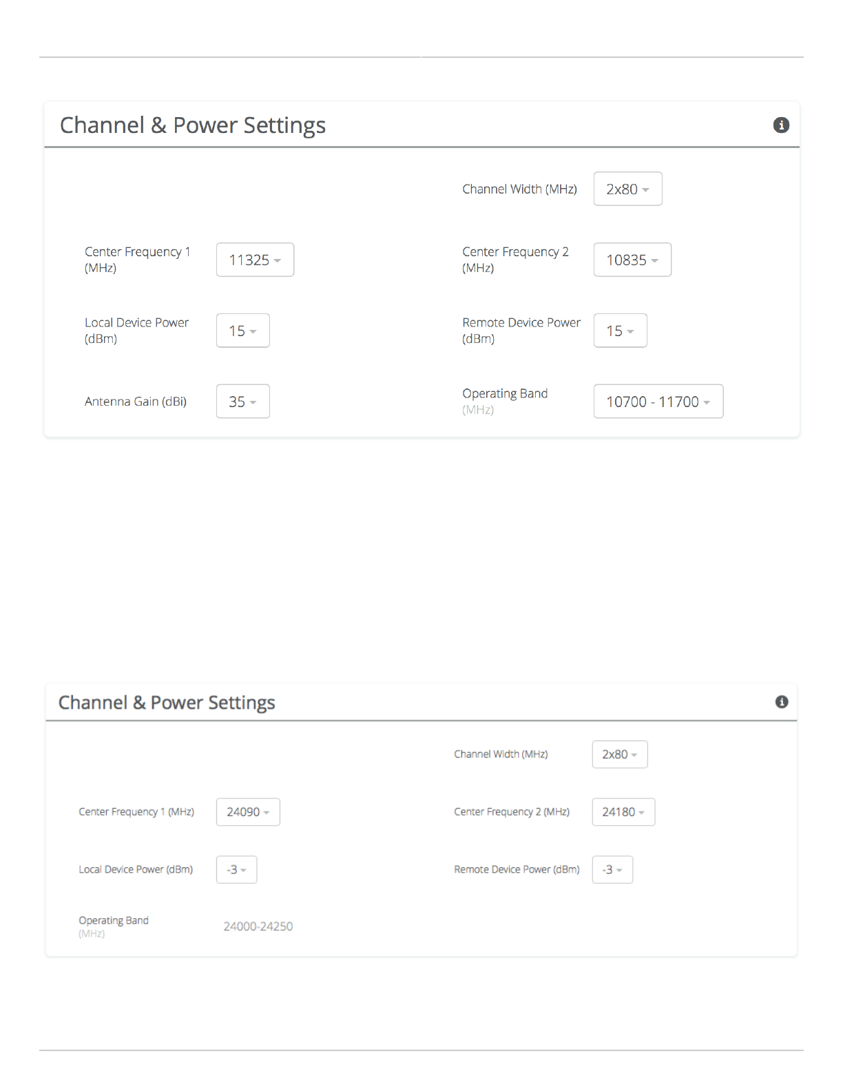
Managing Channel & Power Settings
The Channel and Power Settings panel allows for either automatic or manual changes to frequency, channel width,
and power for either one or two channels.
B5/B5c
Auto Everything - Automatically configure channel, channel width and power to optimize performance based on
●
spectrum data.
Channel Width (MHz) - In Manual Mode, choose the number of link channels (single or dual) and the
●
channel width for each (Example: 2x80 MHz represents two channels with 80 MHz each, totaling 160 MHz).
Maximum Channel Width (MHz) - Select the maximum channel width Auto Everything is allowed to use. The
●
decision for single or dual channel modes will be made automatically. For example, selecting 40 MHz as the
maximum channel width may result in 1x40 or 2x20 mode. Smaller channel widths may also be selected based
on RF conditions. Auto Everything is designed to maintain the highest link bandwidth while maintaining link
stability.
Center Frequency (1 & 2) - In Off (Manual) mode, select the center frequency of the channel used on the link. In
●
all modes, the center frequency represents the absolute center of the selected channel width without any
offset, and the center can be moved in 5 MHz increments. If Auto Everything is set to On, the Channel(s) will be
automatically set, and not editable.
Tx Power (1 & 2) - Set the desired transmit power level. The allowed options are determined by a combination
●
of country and chosen frequency. If Channel Width is set to 1xN MHz, Channel 2 will not be used. If Auto
Everything is set to On, Tx Power will be automatically set, and not editable. In "FD" mode, Power 1 and Power 2
represent transmit power on the local and remote sides, respectively.
Local and Remote Antenna Gain (dBi) - For connectorized radios, set the gain according to antenna
●
specifications and subtract out any cable/connector loss. These values will not be shown on radios with
integrated antennas.
Channel Recommendations - List of channel widths, center frequencies, and Tx powers that Auto Everything
●
would choose in order of preference (if enabled).
Mimosa Backhaul and B24 Help Content
Mimosa Backhaul Channel & Power
Copyright © 2018 Mimosa Page Page 30
B5-Lite/C5c PTP
Auto Everything - Automatically configure channel, channel width and power to optimize performance based on
●
spectrum data.
Channel Width (MHz) - In Manual Mode, choose the channel width (20, 40, or 80 MHz).
●
Maximum Channel Width (MHz) - Select the maximum channel width Auto Everything is allowed to use. Smaller
●
channel widths may also be selected based on RF conditions. Auto Everything is designed to maintain the
highest link bandwidth while maintaining link stability.
Center Frequency - In Off (Manual) mode, select the center frequency of the channel used on the link. In all
●
modes, the center frequency represents the absolute center of the selected channel width without any offset,
and the center can be moved in 5 MHz increments. If Auto Everything is set to On, the Channel will be
automatically set, and not editable.
Tx Power - Set the desired transmit power level. The allowed options are determined by a combination of
●
country and chosen frequency. If Auto Everything is set to On, the Channel & Tx Power will be automatically set,
and not editable.
Channel Recommendations - List of channels, center frequencies, and Tx powers that Auto Everything would
●
choose in order of preference (if enabled).
Mimosa Backhaul and B24 Help Content
Mimosa Backhaul Channel & Power
Copyright © 2018 Mimosa Page Page 31
B11
Channel Width (MHz) - In Manual Mode, choose the channel width (20, 40, or 80 MHz).
●
Center Frequency (1 & 2) - Select the center frequency of the channel used on the link. In all modes, the center
●
frequency represents the absolute center of the selected channel width without any offset, and the center can
be moved in 5 MHz increments.
Local and Remote Device Power - Set the desired transmit power levels on the AP.
●
Antenna Gain (dBi) - Set the gain according to antenna specifications and subtract out any cable/connector
●
loss.
Operating Band (MHz) - Select the frequency range in which the radio will operate: 10000-10700 or 10700-
●
11700.
Mimosa Backhaul and B24 Help Content
Mimosa Backhaul Channel & Power
Copyright © 2018 Mimosa Page Page 32
Note: Tx power selections may be limited based on your regulatory domain (refer to the Maximum Power chart for
more details).
B24
Channel Width (MHz) - In Manual Mode, choose the channel width (20, 40, or 80 MHz).
●
Center Frequency (1 & 2) - Select the center frequency of the channel used on the link. In all modes, the center
●
frequency represents the absolute center of the selected channel width without any offset, and the center can
be moved in 5 MHz increments.
Local and Remote Device Power - Set the desired transmit power levels on the AP.
●
Operating Band (MHz) - Select the frequency range in which the radio will operate: 24000-24250.
●
Note: Tx power selections may be limited based on your regulatory domain (refer to the Maximum Power chart for
more details).

Mimosa Backhaul and B24 Help Content
Mimosa Backhaul Channel & Power
Copyright © 2018 Mimosa Page Page 33
Related
Using TDMA-FD Mode - Application note describing how to apply FD mode in challenging spectrum.
Mimosa Backhaul and B24 Help Content
Mimosa Backhaul Channel & Power
Copyright © 2018 Mimosa Page Page 34
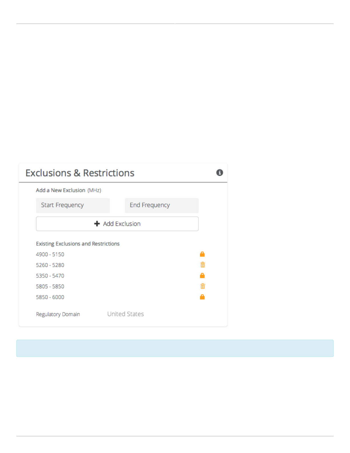
Managing Exclusions & Restrictions
Exclusions list the frequency ranges in which the device should not operate. The Auto Everything feature will avoid
these frequency bands. The excluded bands will be shown as shaded regions on the Spectrum Analyzer.
Start - Specify the lower limit for the exclusion range, not including this frequency.
●
End - Specify the upper limit for the exclusion range, not including this frequency.
●
Add Exclusions - The button to add the Start and End frequency range to the exclusion list.
●
Existing Exclusions and Restrictions - Exclusions can be removed from the list by clicking on the trash icon. The
●
restricted bands with the lock icon cannot be removed. They are protected because of regulatory requirements.
Regulatory Domain - The country in which the device has been configured to run.
●
In the United States, if either the AP or STA are within a 60 km radius of a Terminal Doppler Weather Radar (TDWR)
location, one or more 30 MHz restrictions are automatically created to avoid the TDWR operating frequencies.
The B24 does not support user added exclusions.
The B24 does not support user added exclusions.

Mimosa Backhaul and B24 Help Content
Mimosa Backhaul Link
Copyright © 2018 Mimosa Page Page 35
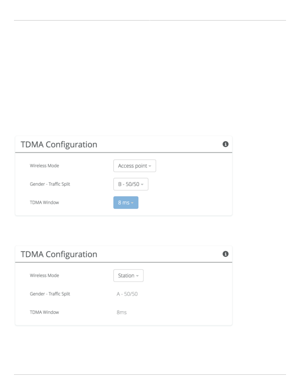
TDMA Configuration Settings
The TDMA Configuration panel contains controls for configuring and fine tuning TDMA performance. One side of the
radio link must be set as an Access point, and the other set as a Station. The Station inherits the other settings from
the AP, so the other fields are grayed out and not accessible when Station is selected.
B5/B5c
Wireless Mode - Choose whether the device will act as an Access Point or a Station.
●
Gender - Traffic Split - The radio can be configured to allocate bandwidth symmetrically (50/50) or biased
●
towards downstream (75/25) in environments where traffic direction is expected to be heavier in one direction
than the other. With an asymmetrical split, the local radio is represented first in the slash notation,
(local/remote). For example, in the (75/25) split, the local radio gets 75, while the remote radio gets 25. If
"Auto" is selected the radio will automatically determine, based upon traffic flow, which ratio will be used. The
radio will continue to evaluate the flow and adjust accordingly.
TDMA Window - Determines the length of the transmit time slot in milliseconds. If "Auto" is selected as the
●
Gender-Traffic Split, this value is set dynamically.
Note: To enable spectrum reuse, both Gender-Traffic Split and TDMA Window must each be set to the same value
for all collocated radios. Further, "Auto" must not be selected as the TDMA Window when radios are collocated.
B5-Lite
Wireless Mode - Choose whether the device will act as an Access Point or a Station.
●
Gender - Traffic Split - The radio can be configured to allocate bandwidth symmetrically (50/50) or biased
●
towards downstream (75/25) in environments where traffic direction is expected to be heavier in one direction
than the other. With an asymmetrical split, the local radio is represented first in the slash notation,
(local/remote). For example, in the (75/25) split, the local radio gets 75, while the remote radio gets 25. If
"Auto" is selected the radio will automatically determine, based upon traffic flow, which ratio will be used. The
radio will continue to evaluate the flow and adjust accordingly.
TDMA Window - Determines the length of the transmit time slot in milliseconds. If "Auto" is selected as the
●
Gender-Traffic Split, this value is set dynamically.
B11
Wireless Mode - Choose whether the device will act as an Access Point or a Station.
●
Gender - Traffic Split - The radio can be configured to allocate bandwidth symmetrically (50/50) or biased
●
towards downstream (75/25) in environments where traffic direction is expected to be heavier in one direction
than the other. With an asymmetrical split, the local radio is represented first in the slash notation,
(local/remote). For example, in the (75/25) split, the local radio gets 75, while the remote radio gets 25. If
"Auto" is selected the radio will automatically determine, based upon traffic flow, which ratio will be used. The
radio will continue to evaluate the flow and adjust accordingly.
TDMA Window - Determines the length of the transmit time slot in milliseconds. If "Auto" is selected as the
●
Gender-Traffic Split, this value is set dynamically.
B24
Wireless Mode - Choose whether the device will act as an Access Point or a Station.
●
Gender - Traffic Split - The radio can be configured to allocate bandwidth symmetrically (50/50) or biased
●
Mimosa Backhaul and B24 Help Content
Mimosa Backhaul Link
Copyright © 2018 Mimosa Page Page 36
towards downstream (75/25) in environments where traffic direction is expected to be heavier in one direction
than the other. With an asymmetrical split, the local radio is represented first in the slash notation,
(local/remote). For example, in the (75/25) split, the local radio gets 75, while the remote radio gets 25. If
"Auto" is selected the radio will automatically determine, based upon traffic flow, which ratio will be used. The
radio will continue to evaluate the flow and adjust accordingly.
TDMA Window - Determines the length of the transmit time slot in milliseconds. If "Auto" is selected as the
●
Gender-Traffic Split, this value is set dynamically.
Note: To enable spectrum reuse, both Gender-Traffic Split and TDMA Window must each be set to the same value
for all collocated radios. Further, "Auto" must not be selected as the TDMA Window when radios are collocated and
sharing the same frequencies.
Example Access Point Settings
Example Station Settings

Mimosa Backhaul and B24 Help Content
Mimosa Backhaul Link
Copyright © 2018 Mimosa Page Page 37
Rate Adaptation
Rate Adaptation Mode - Choose PER (default) or EVM. The PER mode adjusts modulation based on the Tx Packet
●
Error Rate calculated on the local radio. The EVM mode adjusts modulation based on the Error Vector Magnitude
reported by the remote radio.
PHY Rate - Choose Conservative (default) or Aggressive. The Conservative mode results in the lowest PER, but
●
can also prevent higher modulation. The Aggressive mode optimizes modulation, but can also result in higher
PER.
The table below describes the PER limit above which Rate Adaptation will reduce modulation to maintain a stable
link.
Rate Adaptation Mode PHY Rate B5, B5c, B5-Lite
PER Allowed
B11
PER Allowed
EVM Conservative 5 3
Aggressive 10 5
PER Conservative 3 3
Aggressive 5 5
Mimosa Backhaul and B24 Help Content
Mimosa Backhaul Link
Copyright © 2018 Mimosa Page Page 38
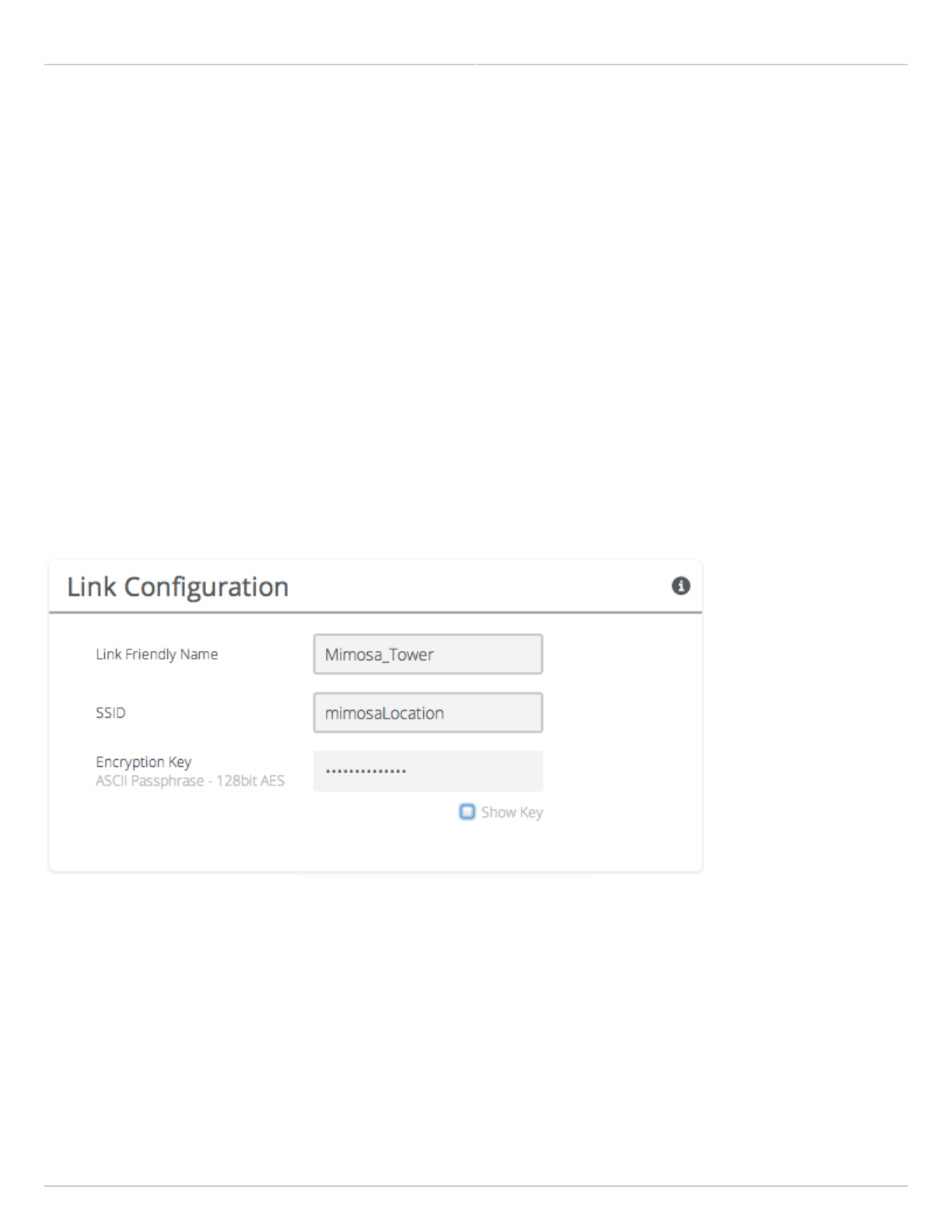
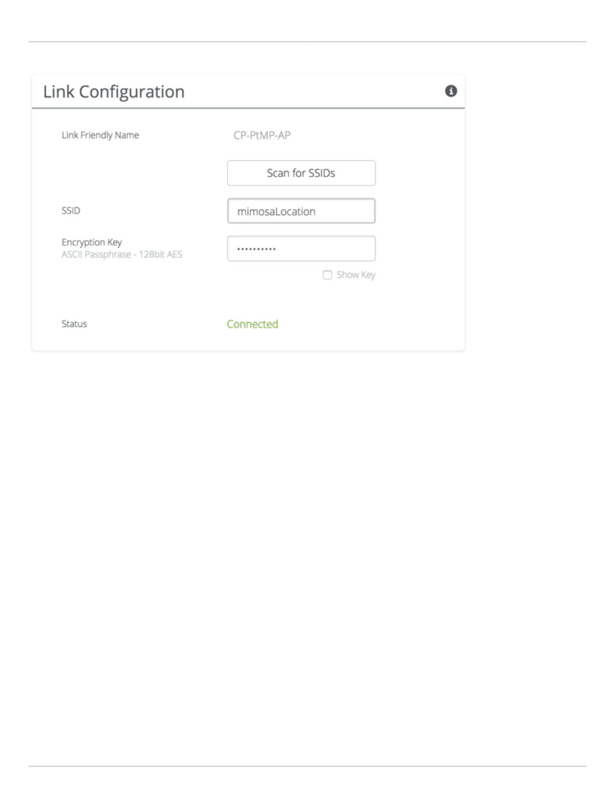
Link Configuration Settings
The Link Configuration panel includes controls to define the SSID and passphrase between radios:
Link Friendly Name - A friendly name to describe the link between the Access Point (AP) and Station. This name
●
is used to differentiate amongst other links.
SSID - The wireless link name used by both radios. Both AP and Station must use the same SSID to
●
communicate with each other.
Encryption Key - Enter the ASCII Passphrase to connect with the broadcasted SSID. Select "Show Key" to see
●
passphrase in plain text. Enter any combination of printable characters. The passphrase should be between 8 to
63 characters in length. The Encryption Key must be the same on both the Access Point and Station for them to
communicate with each other.
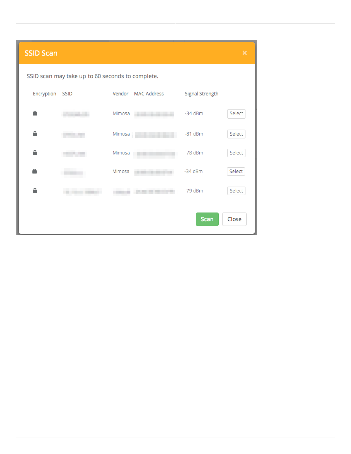
Scan for SSIDs - On a radio configured as a Station, click this button to display a list of Access Point SSIDs.
●
Status - Indicates whether the AP and Station are "Connected" (associated) or "Not Connected" (disassociated).
●
Please ensure that the SSID, Encryption Key, and firmware versions are the same. Additionally, ensure that the IP
addresses are different, and on the same subnet.
Example Access Point Link Configuration
Example Station Link Configuration
Mimosa Backhaul and B24 Help Content
Mimosa Backhaul Link
Copyright © 2018 Mimosa Page Page 39
Example SSID Scan after pressing the "Scan for SSIDs" button. To connect to a particular SSID, click the "Select"
button.
Mimosa Backhaul and B24 Help Content
Mimosa Backhaul Link
Copyright © 2018 Mimosa Page Page 40
Mimosa Backhaul and B24 Help Content
Mimosa Backhaul Location
Copyright © 2018 Mimosa Page Page 41
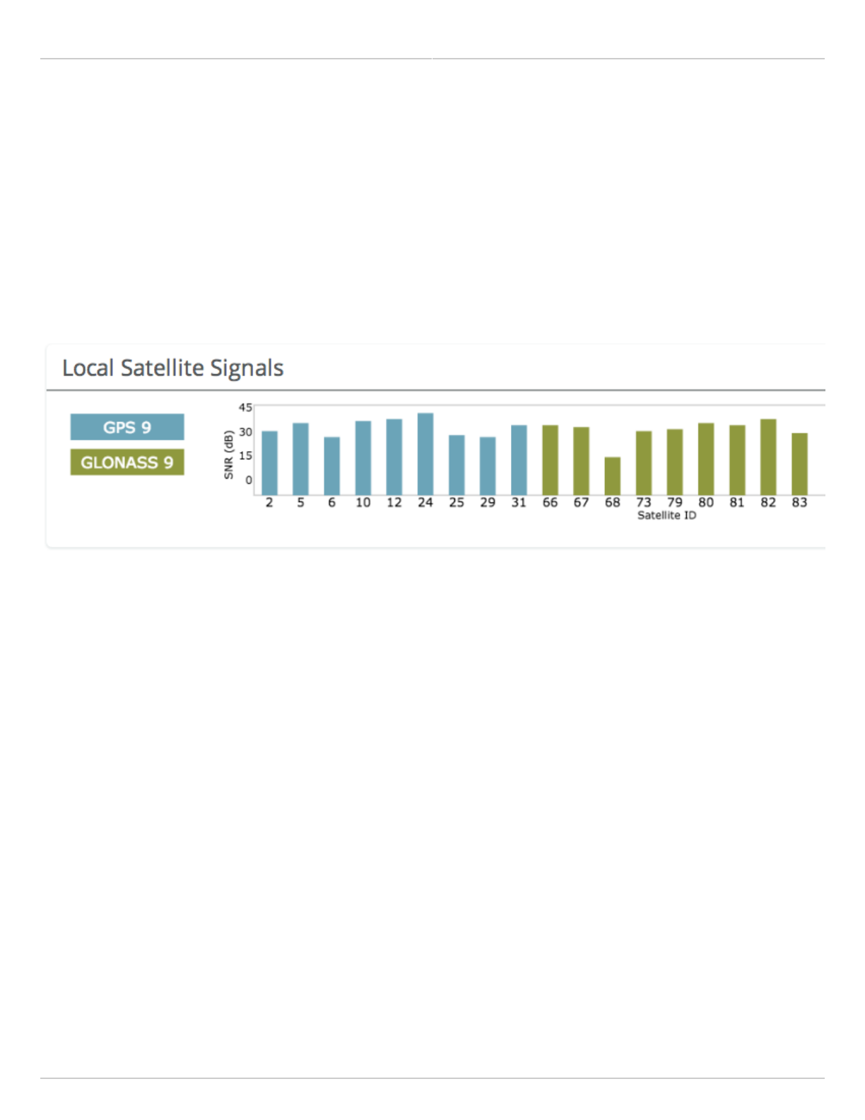
Interpreting Local Satellite Signals
Product Applicability: B5/B5c, B11, B24
The Local Satellite Signals panel contains a chart showing both GPS and GLONASS satellites in blue and green,
respectively, from which the radio can obtain position and timing data used for synchronization. Each numbered
column represents a unique satellite with the columns’ amplitude representing the signal to noise ratio of the
satellite’s signal at the radio’s receiver. The number of satellites the radio detects and the SNR of each both
contribute to clock accuracy.
Mimosa Backhaul and B24 Help Content
Mimosa Backhaul Location
Copyright © 2018 Mimosa Page Page 42
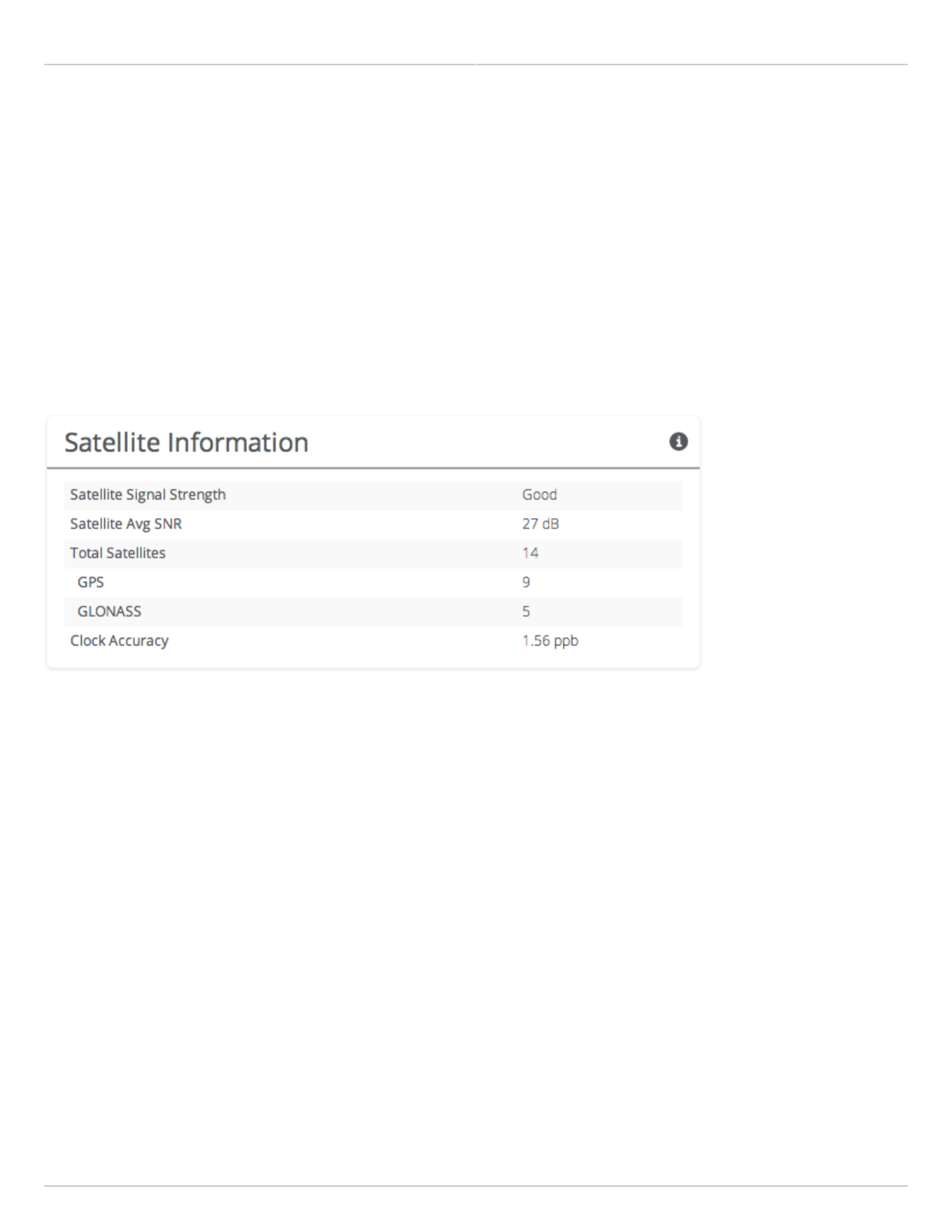
Reading Satellite Information
Product Applicability: B5/B5c, B11, B24
The Satellite Information panel contains values that represent and contribute to clock accuracy. Good GPS signal
strength is required for maximum performance, as the GPS is used to synchronize timing between devices.
Satellite Signal Strength - Qualitative assessment based on all items below; also displayed on the Dashboard.
●
Satellite Avg SNR - Average signal to noise ratio amongst satellites.
●
Total Satellites - Sum of detected GPS and GLONASS satellites.
●
GPS - Number of GPS satellites detected.
●
GLONASS - Number of GLONASS satellites detected.
●
Clock Accuracy - Timing signal accuracy measured in parts per billion (ppb).
●

Mimosa Backhaul and B24 Help Content
Mimosa Backhaul Location
Copyright © 2018 Mimosa Page Page 43
Viewing Location Data
Product Applicability: B5/B5c, B11
Status table showing location, altitude, and heading for both the local and remote devices, as well as the link
distance between them.
Mimosa Backhaul and B24 Help Content
Mimosa Backhaul Site Survey
Copyright © 2018 Mimosa Page Page 44
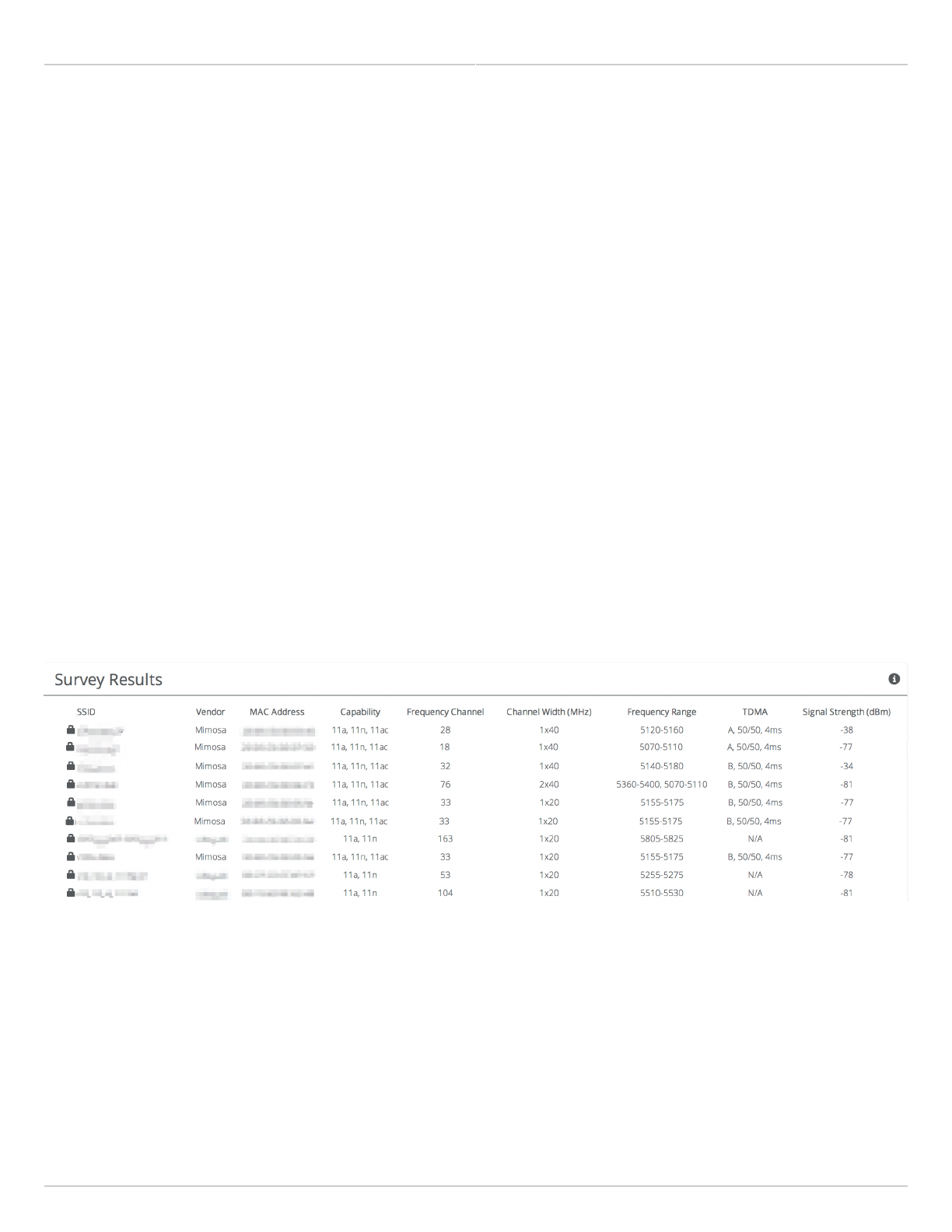
Reading Site Survey Results
The Survey Results status table summarizes the results of a site survey, including the SSIDs broadcast by other
devices, their configuration and capabilities. Note that the Site Survey function will only detect other Access Points.
Stations are passive, so will not beacon or show up in Site Survey results.
The table provides the following data per device found:
SSID - The wireless link name advertised by each detected AP.
●
Capability - Indicates which 802.11 (Wi-Fi technology standard) is support by the device. Options include A, G,
●
N, AC.
MAC Address - The device's unique identifier.
●
Vendor - The name of the device manufacturer (if known).
●
Wi-Fi Channel - Lists the channel on which the device operates.
●
Channel Width - The size (in MHz) of the channel on which the device operates.
●
Frequency Range - The specific frequency range (in MHz) within the Wi-Fi channel that the device operates.
●
Signal Strength - The received power level (in dBm) from each detected AP.
●
Note: The Site Survey will temporarily interrupt your link. Once started, this process cannot be stopped until
complete.
Use the Start Survey button to place the radio into the scan mode to search for 802.11-compatible access points.
The Last Updated field indicates (down to the second) when the last Site Survey was requested.
It is important to note that running a site survey will temporarily take down your link. Once activated, this process
cannot be stopped until complete. Please plan accordingly.
Mimosa Backhaul and B24 Help Content
Mimosa Backhaul General
Copyright © 2018 Mimosa Page Page 45
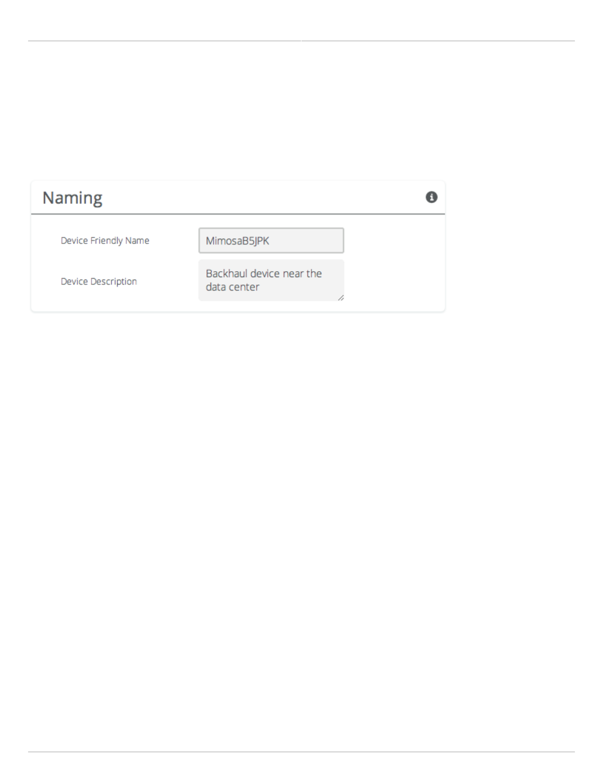
Setting a Device Name and Description
The device name and description are local identifiers for administrative purposes, and are not used as part of the
wireless link.
Device Friendly Name - Name for the local device displayed on the Dashboard.
●
Device Description - A more detailed device description (up to 150 characters) for administrative purposes.
●
Mimosa Backhaul and B24 Help Content
Mimosa Backhaul General
Copyright © 2018 Mimosa Page Page 46
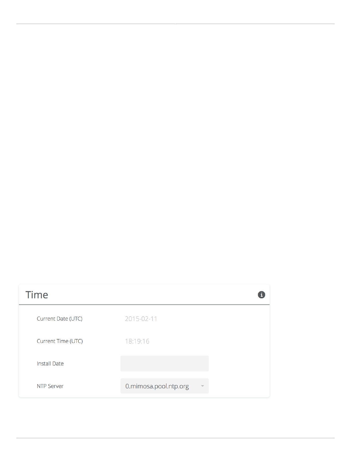
Reading the Date/Time & Setting the Install Date
The Time panel shows the current date and time in Coordinated Universal Time (UTC). The Install Date input box can
be used for administrative purposes, but it is optional and has no other affect.
B5/B5c
Current Date (UTC) - Current date as set by GPS.
●
Current Time (UTC) - Current time as set by GPS.
●
Install Date - Used to track the date that the device was installed.
●
B5-Lite
Current Date (UTC) - Current date as set by the NTP Server.
●
Current Time (UTC) - Current time as set by the NTP Server.
●
Install Date - Used to track the date that the device was installed.
●
NTP Server - Domain name or IP address of network time server.
●
B11
Current Date (UTC) - Current date as set by GPS.
●
Current Time (UTC) - Current time as set by GPS.
●
Install Date - Used to track the date that the device was installed.
●
B24
Current Date (UTC) - Current date as set by GPS.
●
Current Time (UTC) - Current time as set by GPS.
●
Install Date - Used to track the date that the device was installed.
●
Mimosa Backhaul and B24 Help Content
Mimosa Backhaul General
Copyright © 2018 Mimosa Page Page 47
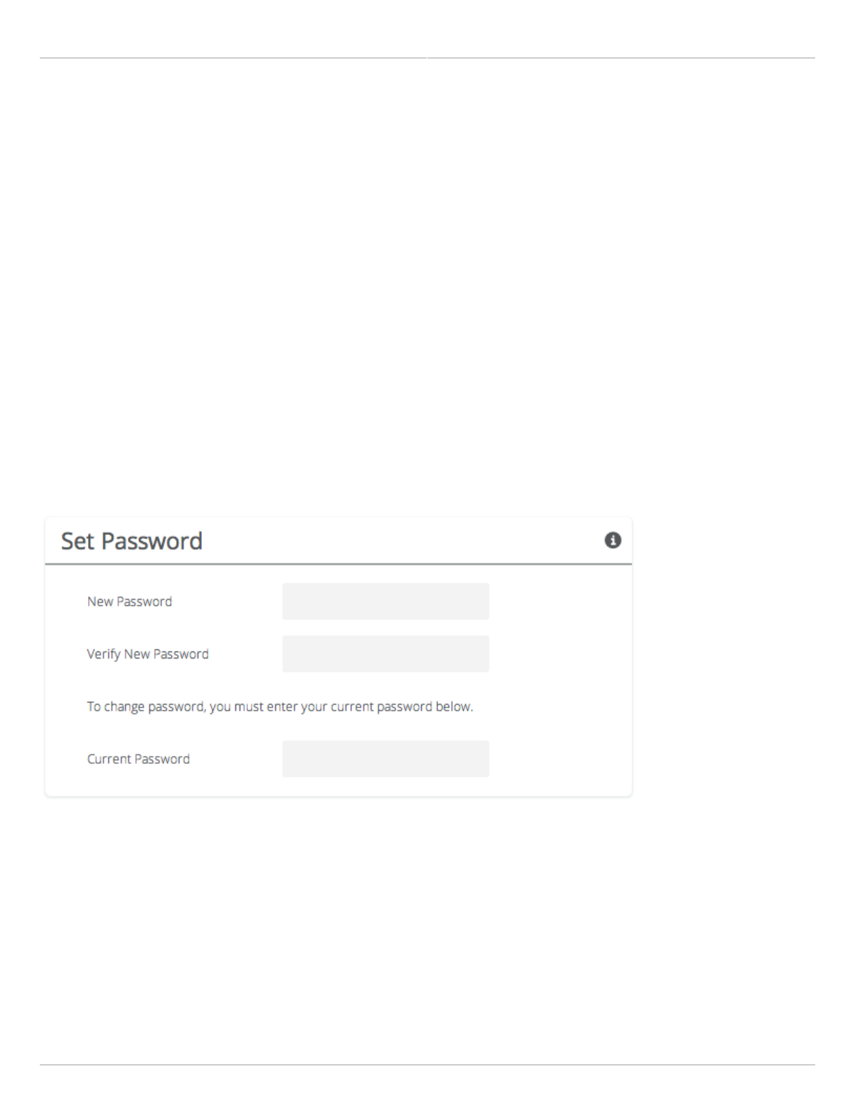
Setting a Password
Enter the new password in both the New Password and Verify New Password input boxes to validate that they were
typed correctly. To finalize the change, enter the existing password and then save. The default password should be
changed during device configuration to protect your network.
New Password - Enter the new password.
●
Verify New Password - Re-enter the new password (to confirm).
●
Current Password - Enter the existing password (as a security measure).
●
The Password rules are as follows for choosing a password:
It must be between 6 to 64 characters.
●
It can use capital (A-Z) or lower case (a-z) characters, excluding space.
●
Valid special characters for the password include ! " # $ % & ' ( ) * + , - . / : ; < = > ? [ ] ^ _ ` { | } ~
●
The password cannot be blank.
●
The password may not have a leading or trailing space.
●
There is no complexity required for the password.
●
Mimosa Backhaul and B24 Help Content
Mimosa Backhaul General
Copyright © 2018 Mimosa Page Page 48
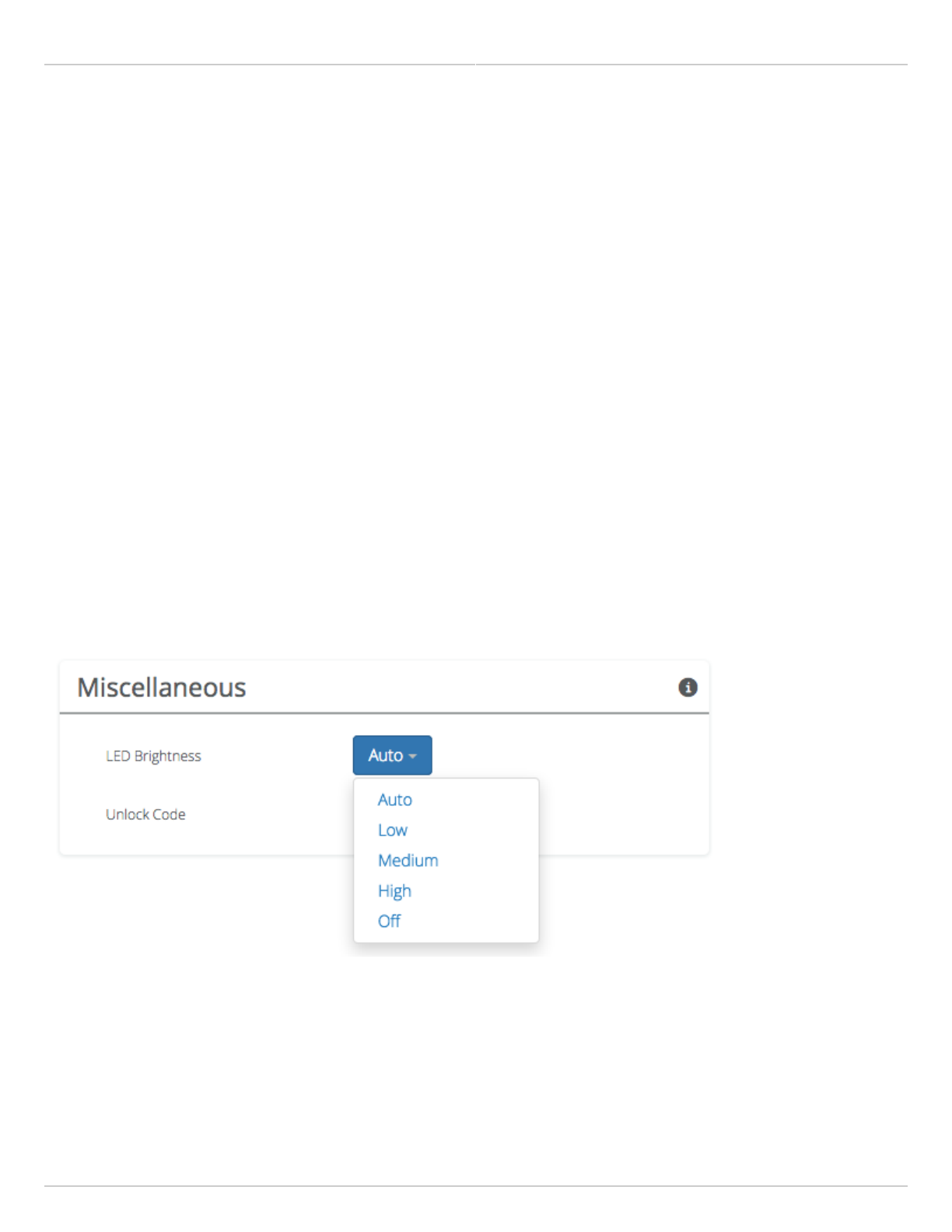
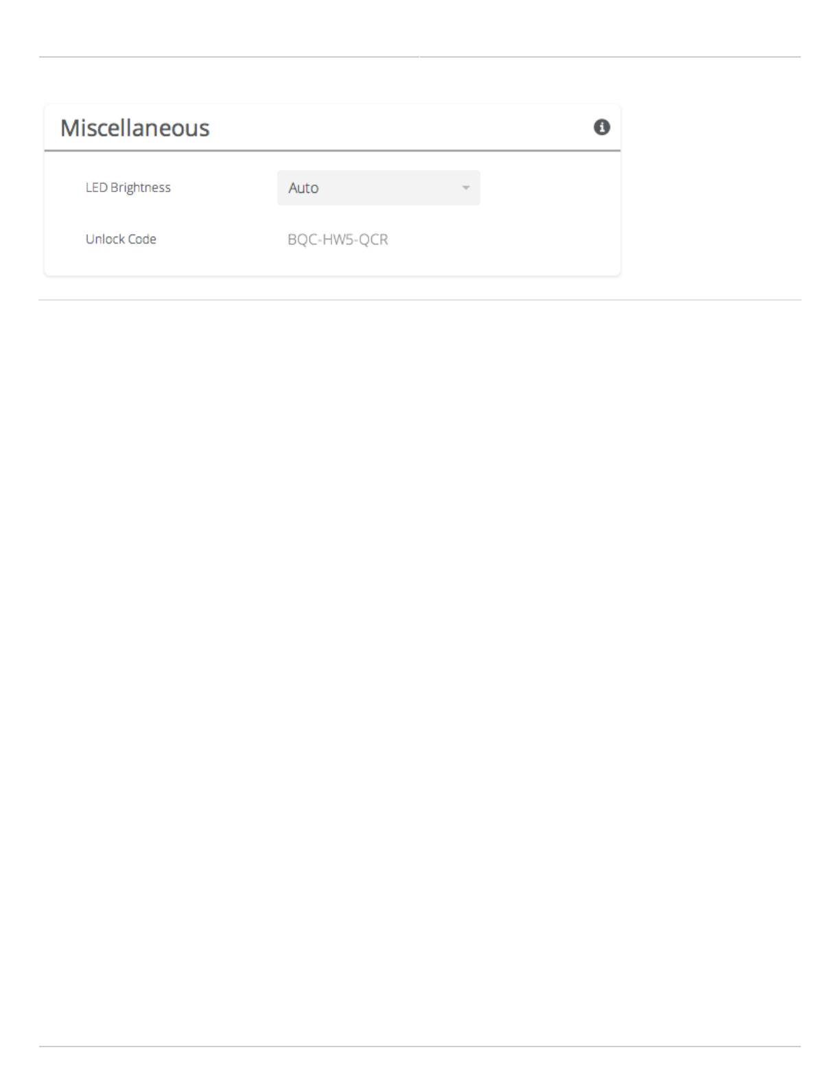
General Miscellaneous Settings
The Miscellaneous panel contains general functionality not described elsewhere.
B5/B5c
LED Brightness - Changes the intensity of the status indicator lights on the device exterior. The Auto option
●
adjusts the amount of light based upon ambient conditions. Manual options include Low, Medium, High and Off.
Unlock Code - Displays the code used to unlock the device.
●
B5-Lite
Unlock Code - Displays the code used to unlock the device.
●
B11
LED Brightness - Changes the intensity of the status indicator lights on the device exterior. The Auto option
●
adjusts the amount of light based upon ambient conditions. Manual options include Low, Medium, High and Off.
Unlock Code - Displays the code used to unlock the device.
●
B24
LED Brightness - Changes the intensity of the status indicator lights on the device exterior. The Auto option
●
adjusts the amount of light based upon ambient conditions. Manual options include Low, Medium, High and Off.
Unlock Code - Displays the code used to unlock the device.
●
Mimosa Backhaul and B24 Help Content
Mimosa Backhaul General
Copyright © 2018 Mimosa Page Page 49
Related
Change Unlock Country - Replace an existing unlock code to enable another regulatory domain
Mimosa Backhaul and B24 Help Content
Mimosa Backhaul Management
Copyright © 2018 Mimosa Page Page 50
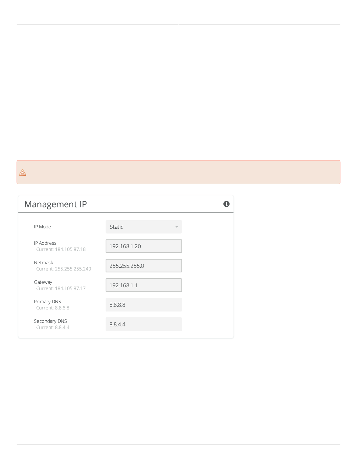
Setting the Management IP Address
The Management IP panel contains controls for setting the device's network address, subnet, gateway and DNS
servers.
IP Mode - Select the preferred mode of network addressing: Static or DHCP+Static Failover. If Static is chosen,
●
the device will always use the IP address that has been assigned. If DHCP+Static Failover is chosen, and a
DHCP server is available, then the addresses are automatically assigned by the DHCP server. If a DHCP server is
unavailable, the device will use the static IP address listed below.
IP Address - The network address used to manage the device.
●
Netmask - The subnet mask that defines the network subnet.
●
Gateway - The gateway address for the subnet.
●
Primary DNS - The first DNS server IP Address. Default is 8.8.8.8.
●
Secondary DNS - The backup DNS server IP Address. Default is 8.8.4.4.
●
Note that the wired Ethernet interface is configured by default to use DHCP with a static failover to the IP
Note that the wired Ethernet interface is configured by default to use DHCP with a static failover to the IP
address like in the screen capture below.
address like in the screen capture below.
Mimosa Backhaul and B24 Help Content
Mimosa Backhaul Management
Copyright © 2018 Mimosa Page Page 51
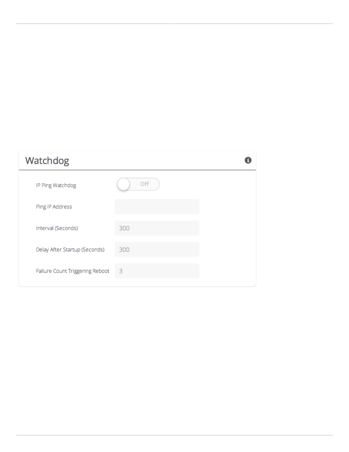
Enabling Watchdog
The Watchdog panel contains controls to monitor a remote host and reboot the local device under configurable
failure conditions.
IP Ping Watchdog - Enables the IP Ping Watchdog feature, which reboots the device if it cannot ping a certain IP
●
after a number of retry attempts.
Ping IP Address - Enter the IP address of the device to ping.
●
Interval - Set the number of seconds (1-3600) between ping attempts.
●
Delay After Startup - Set the delay in number of seconds (1-3600) between device start up and the first ping
●
attempt.
Failure Count Triggering Reboot - Set the number of failed ping attempts (1-100) before rebooting the device.
●
WARNING: rebooting will take the device offline.
Mimosa Backhaul and B24 Help Content
Mimosa Backhaul Management
Copyright © 2018 Mimosa Page Page 52
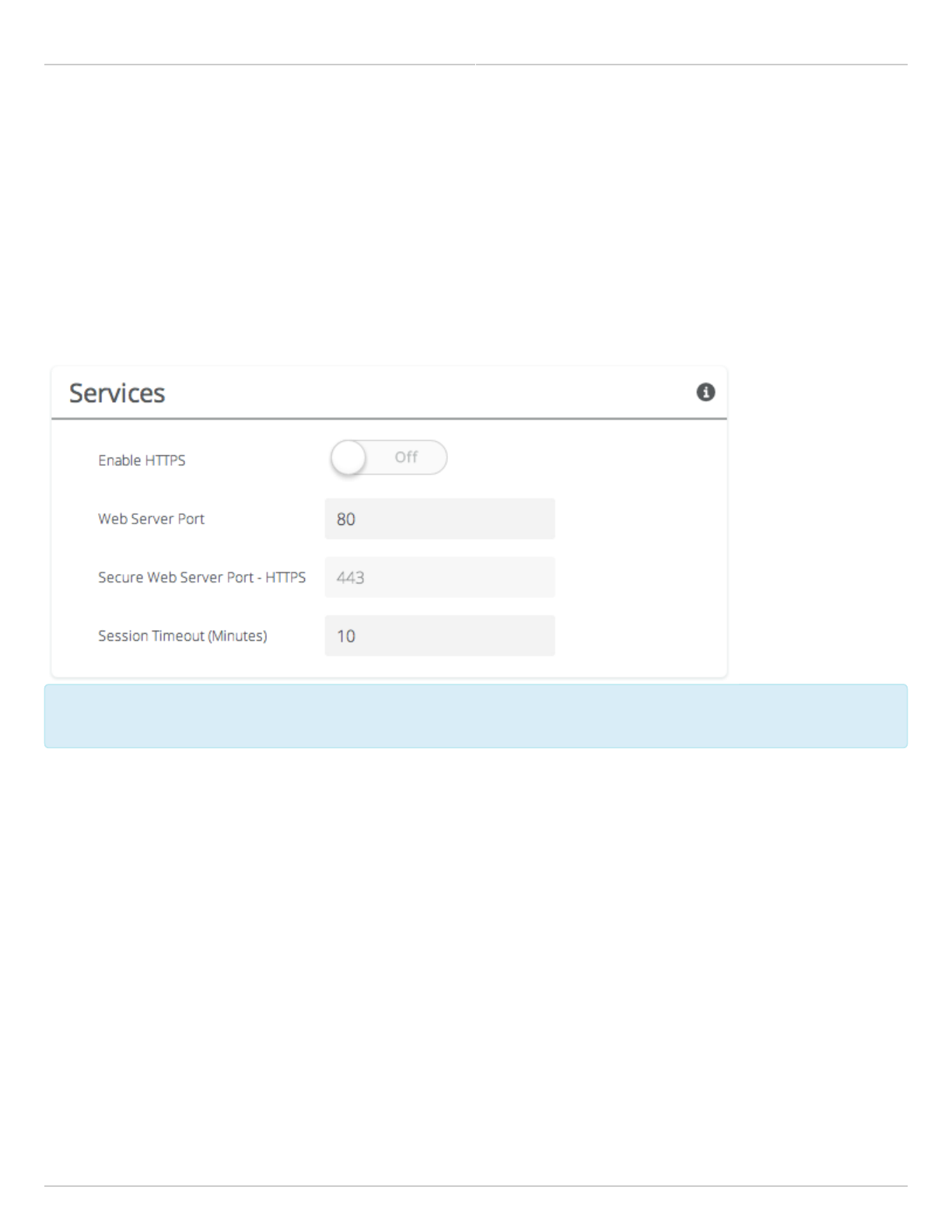
Management Services
The Services panel holds controls to secure management traffic by specifying how it should be served over the
network.
Enable HTTPS - Use SSL to access the web interface of this device.
●
Web Server Port - Indicate which TCP port will be used for the web server. This web server is for the web
●
interface.
Secure Web Server Port - Indicate which TCP port will be used for the secure web server.
●
Session Timeout - Set the number of minutes (0-60) of inactivity that will be allowed on the interface before
●
automatic log-out for sessions. If set to "0", the session will have no timeout.
Following an automatic session timeout, logging back into the device will take you to the Dashboard
Following an automatic session timeout, logging back into the device will take you to the Dashboard
screen.
screen.

Mimosa Backhaul and B24 Help Content
Mimosa Backhaul Management
Copyright © 2018 Mimosa Page Page 53
Management Miscellaneous Settings
The Miscellaneous panel contains controls to enable Mimosa Cloud Management and to select the Ethernet Port data
rate, either automatically or manually.
B5/B5c
Mimosa Cloud Management - Enables the device to use Mimosa Cloud Management tools. Data will be collected
●
and stored the Mimosa Cloud.
Ethernet Port - Set the Ethernet port transfer rate or allow it to be automatically determined. Manually
●
selectable options are 10, 100, or 1000BaseT at either full or half duplex. Note that Auto or 1000BaseT/Full is
recommended so that the Ethernet port does not create a bottleneck.
Autoneg Mode - Select an autonegotiation mode for Ethernet: Auto, Manual Slave, Manual Master, Preferred
●
Slave, Preferred Master. Auto mode is recommended. Manual options may improve interoperability with some
routers and switches.
Rapid Port Shutdown (RPS) - Enabling this option disables the logical link of the Ethernet port for 2 seconds
●
once every 5 minutes if the wireless link disassociates. This function becomes active only after initial
association, and repeats the off/on cycle until the link re-associates. This speeds convergence of routing and
switching protocols used in the network.
Flow Control - Enables PAUSE frames (part of 802.3x standard) to manage the transmission rate between
●
upstream senders and the Ethernet Interface.
Firewall - Enable this option to protect the management interface from denial of service attacks. Changing this
●
value requires a reboot.
B5-Lite
Mimosa Cloud Management - Enables the device to use Mimosa Cloud Management tools. Data will be collected
●
and stored the Mimosa Cloud.
Ethernet Port - Set the Ethernet port transfer rate or allow it to be automatically determined. Manually
●
selectable options are 10, 100, or 1000BaseT at either full or half duplex. Note that Auto or 1000BaseT/Full is
recommended so that the Ethernet port does not create a bottleneck.
Autoneg Mode - Select an autonegotiation mode for Ethernet: Auto, Manual Slave, Manual Master, Preferred
●
Slave, Preferred Master. The Manual Slave option improves interoperability with some routers and switches.
Rapid Port Shutdown (RPS) - Enabling this option disables the logical link of the Ethernet port for 2 seconds
●
once every 5 minutes if the wireless link disassociates. This function becomes active only after initial
association, and repeats the off/on cycle until the link re-associates. This speeds convergence of routing and
switching protocols used in the network.
Flow Control - Enables PAUSE frames (part of 802.3x standard) to manage the transmission rate between
●
upstream senders and the Ethernet Interface.
Firewall - Enable this option to protect the management interface from denial of service attacks. Changing this
●
value requires a reboot.
B11
Mimosa Cloud Management - Enables the device to use Mimosa Cloud Management tools. Data will be collected
●
and stored the Mimosa Cloud.
Rapid Port Shutdown (RPS) - Enabling this option disables the logical link of the Ethernet port for 2 seconds
●
once every 5 minutes if the wireless link disassociates. This function becomes active only after initial

Mimosa Backhaul and B24 Help Content
Mimosa Backhaul Management
Copyright © 2018 Mimosa Page Page 54
association, and repeats the off/on cycle until the link re-associates. This speeds convergence of routing and
switching protocols used in the network.
Flow Control - Enables PAUSE frames (part of 802.3x standard) to manage the transmission rate between
●
upstream senders and the Ethernet Interface.
Firewall - Enable this option to protect the management interface from denial of service attacks. Changing this
●
value requires a reboot.
B24
Mimosa Cloud Management - Enables the device to use Mimosa Cloud Management tools. Data will be collected
●
and stored the Mimosa Cloud.
Rapid Port Shutdown (RPS) - Enabling this option disables the logical link of the Ethernet port for 2 seconds
●
once every 5 minutes if the wireless link disassociates. This function becomes active only after initial
association, and repeats the off/on cycle until the link re-associates. This speeds convergence of routing and
switching protocols used in the network.
Flow Control - Enables PAUSE frames (part of 802.3x standard) to manage the transmission rate between
●
upstream senders and the Ethernet Interface.
Firewall - Enable this option to protect the management interface from denial of service attacks. Changing this
●
value requires a reboot.
Your firewall must be configured for outbound access to enable Mimosa Cloud Management.
Your firewall must be configured for outbound access to enable Mimosa Cloud Management.
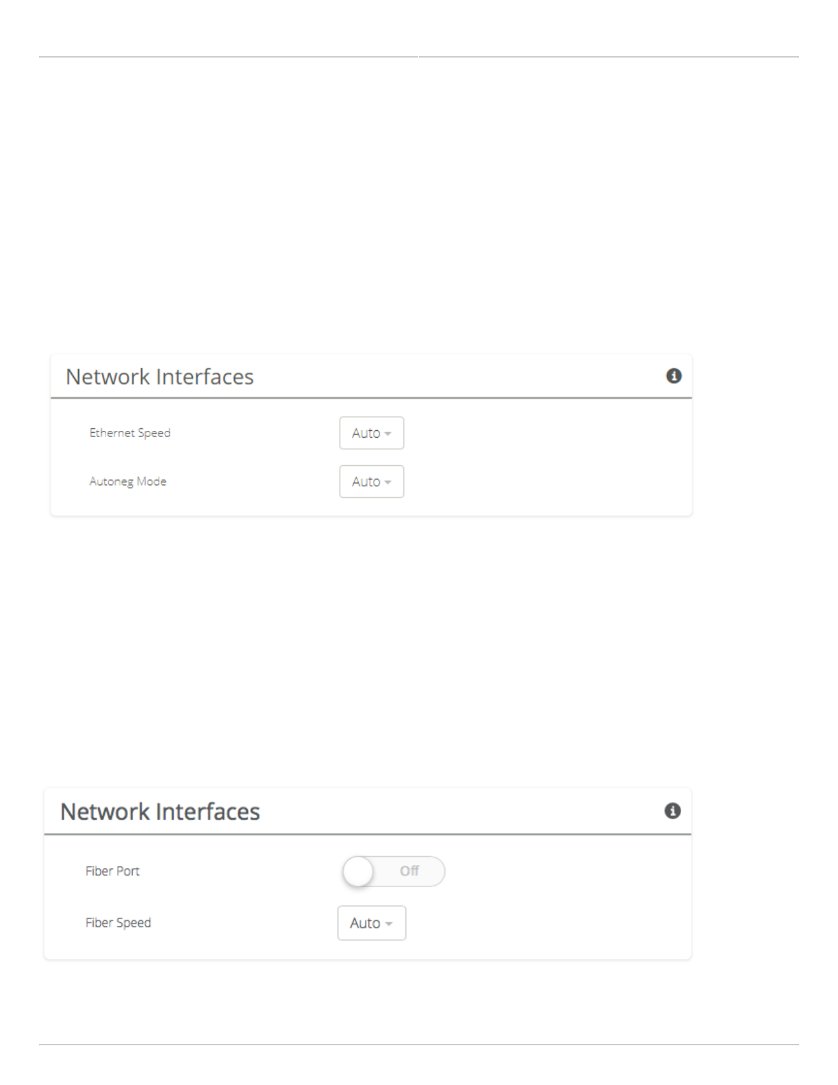
Mimosa Backhaul and B24 Help Content
Mimosa Backhaul Management
Copyright © 2018 Mimosa Page Page 55
Network Interfaces
B5
Ethernet Speed - Set the Ethernet port transfer rate or allow it to be automatically determined. Manually
●
selectable options are 10, 100, or 1000BaseT at either full or half duplex. Note that Auto or 1000BaseT/Full is
recommended so that the Ethernet port does not create a bottleneck.
Autoneg Mode - On B5/B5c or B5-Lite, select an autonegotiation mode for Ethernet: Auto, Manual Slave, Manual
●
Master, Preferred Slave, Preferred Master. The Manual Slave option improves interoperability with some routers
and switches.
B11
Fiber Port - Enable this option to route all data through this port with optical fiber and a small form-
●
factor pluggable (SFP) media adapter. After enabling the Fiber Port, the Ethernet cable must remain connected
to supply power, but it does not pass data. If fiber is enabled and connectivity is lost, the radio may still be
accessed via the 2.4 GHz wireless interface.
Fiber Speed - Set the port transfer rate or allow it to be automatically determined. Manually selectable options
●
are 10, 100, or 1000BaseT at either full or half duplex. Note that Auto is recommended so that the Ethernet port
does not create a bottleneck.
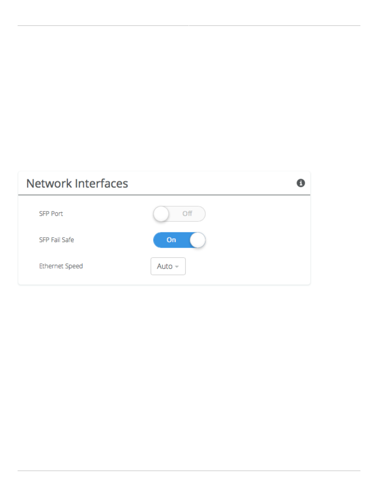
Mimosa Backhaul and B24 Help Content
Mimosa Backhaul Management
Copyright © 2018 Mimosa Page Page 56
B24
Fiber (SFP) Port - When Fiber (SFP) is ON, SFP is used for data and management. Fiber (SFP) Fail Safe option is
●
only available when Fiber (SFP) is ON. When Fiber (SFP) is OFF, by default, Ethernet (RJ45) is used for both data
and management traffic.
Fiber (SFP) Fail Safe - When Fiber (SFP) link goes down, data and management traffic will fail-over to Ethernet
●
(RJ45) and traffic will pass through Ethernet (RJ45) if available. If Fiber (SFP) Fail Safe is OFF, and if Fiber (SFP)
goes down, all traffic will be blocked.
Ethernet (RJ45) Speed - This drop-down allows the user to select one of the following options: Auto, 10, 100,
●
1000BaseT (at full or half duplex). Auto setting is recommended.
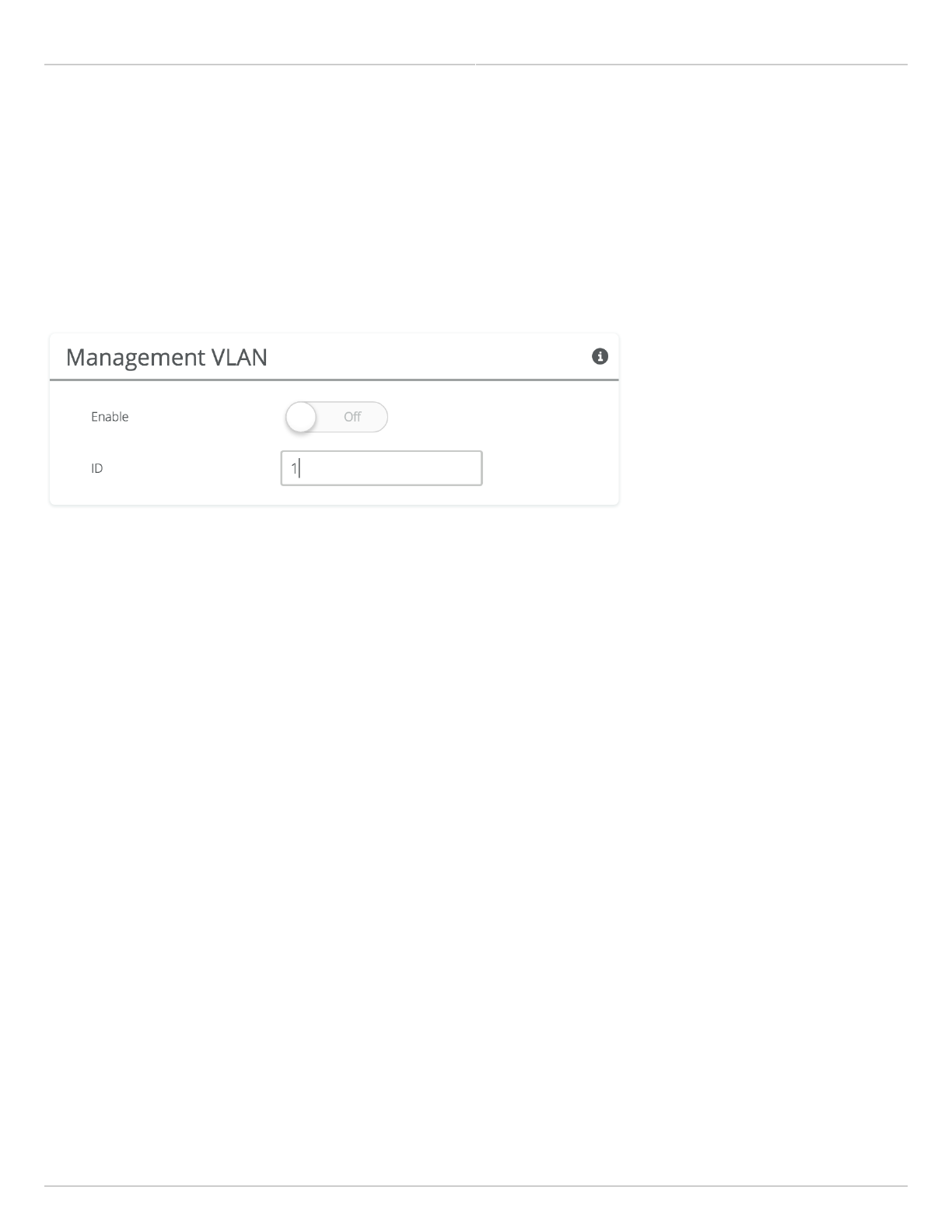
Mimosa Backhaul and B24 Help Content
Mimosa Backhaul Management
Copyright © 2018 Mimosa Page Page 57
VLAN Management
The VLAN Management panel allows the administrator to enable a VLAN (Virtual Local Area Network) for
management traffic. When enabled, all Web Management traffic must originate from a device on that VLAN.
Enable - Use the slider control to turn VLAN Management on or off.
●
ID - The VLAN ID (valid options are 1-4094)
●
You can still connect locally via the 2.4 GHz management console on a B5 or B5c.
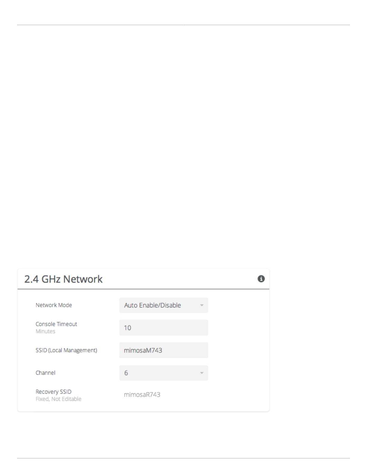
Mimosa Backhaul and B24 Help Content
Mimosa Backhaul 2.4 GHz Console
Copyright © 2018 Mimosa Page Page 58
Enabling the 2.4 GHz Network
Product Applicability: B5/B5c, B11
The 2.4 GHz wireless interface allows local browser-based configuration with any Wi-Fi capable device. This is a low
power interface that performs best if accessed within 60 meters (~200 feet) of the radio. It is completely separate
from the link and has no performance impact on throughput if activated.
Network Mode - Choose to automatically or manually enable or disable the 2.4 GHz management network. The
●
automatic mode turns the 2.4 GHz management network on for a limited time (defined in Console Timeout)
after boot and then turns it off if there is no activity. If a user associates with the radio within the timeout
period, they will not be disconnected.
Console Timeout - Set the number of minutes (1-60) of inactivity that will be allowed on the 2.4 GHz interface
●
before turning it off in Auto mode.
SSID (Local Management) - Set the SSID name for the 2.4 GHz local management interface.
●
Channel - Select the channel on which the 2.4 GHz wireless network will operate.
●
Recovery SSID - This is an non-editable recovery SSID that allows the device to be reset to factory defaults. This
●
is available for 5 minutes after device boot. Disabling the 2.4 GHz management network will not impact
availability of this option. The serial number of the device must be known in order to perform the factory reset.
Note: If you turn off the 2.4 GHz management radio, you can still access the device through the wired LAN interface,
or in-band through the 5 GHz wireless link. During the B5/B5c device reset process, the 2.4 GHz wireless interface is
briefly re-enabled, and then disabled after a timeout.
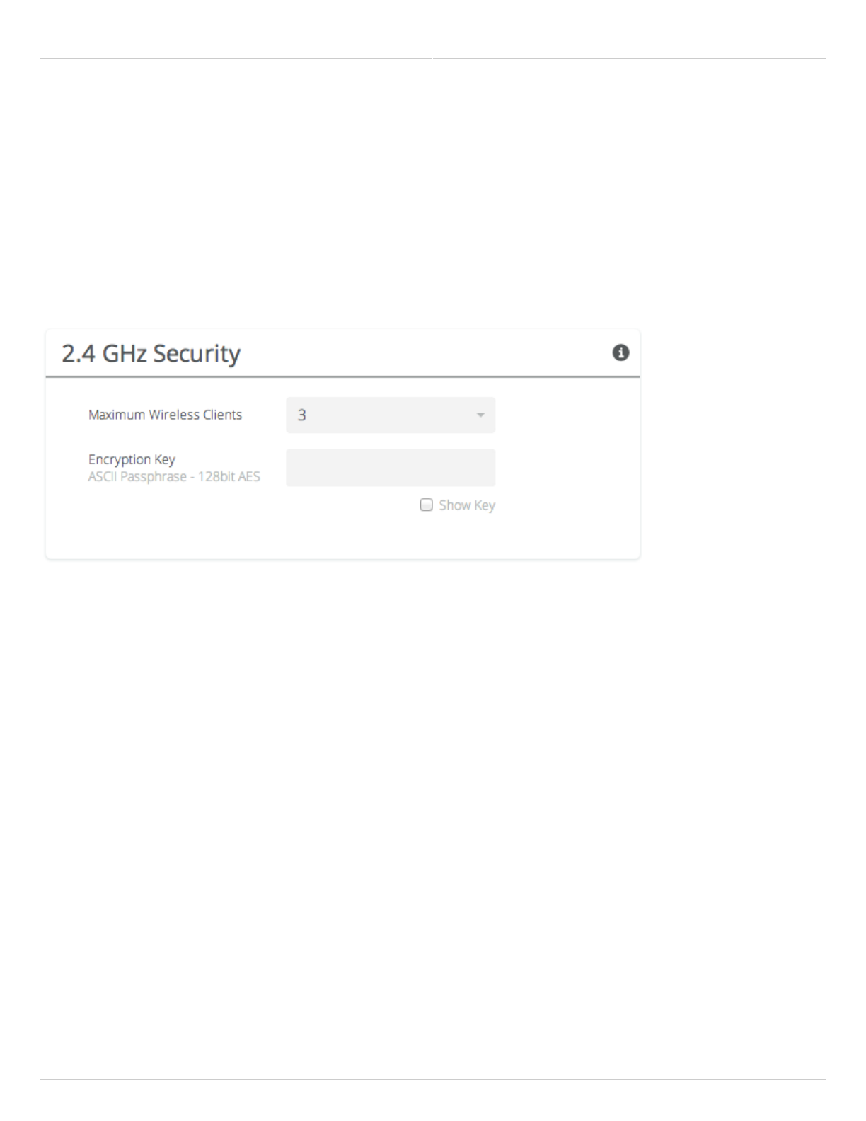
Mimosa Backhaul and B24 Help Content
Mimosa Backhaul 2.4 GHz Console
Copyright © 2018 Mimosa Page Page 59
Setting 2.4 GHz Network Security
Product Applicability: B5/B5c, B11, B24
The 2.4 GHz Security panel contains controls for managing access to the local wireless management network.
Maximum Wireless Clients - Limit the maximum number of wireless clients that can simultaneously access the
●
2.4 GHz management interface.
Encryption Key - Enter an ASCII Passphrase for gaining access to the 2.4 GHz management interface.
●
Show Key (checkbox) - Check to display the Encryption Key in clear text for verification before saving the
●
change.
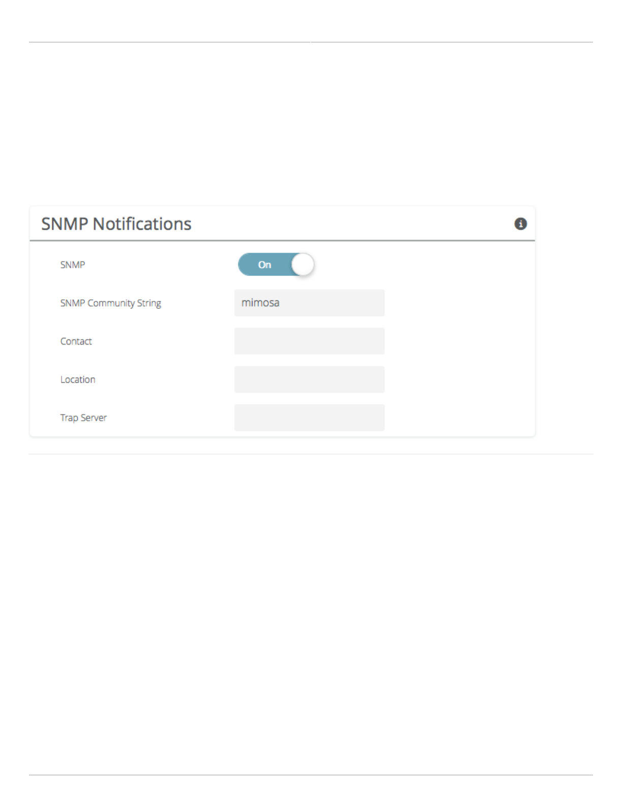
Mimosa Backhaul and B24 Help Content
Mimosa Backhaul Notifications
Copyright © 2018 Mimosa Page Page 60
Enabling SNMP Notifications
Enable the SNMP service to allow SNMP requests and enable push notifications to a remote server.
SNMP - Enable or disable SNMP service on the local device.
●
SNMP Community String - Enter a string for use during client authentication.
●
Contact - Specify an (optional) administrative contact for the SNMP system.
●
Location - Specify the (optional) physical location for the SNMP system.
●
Trap Server - Define the server to receive the notifications.
●
Related
SNMP Usage Examples: Get / Walk / Table - Sample commands for retrieving values
SNMP Object Names - Query values using SNMP Object Names defined within the Mimosa MIB file
SNMP Traps - Configure outgoing notifications for specific events
SNMP Traps OIDs - OIDs associated with the SNMP Traps
SNMP MIB Download - Available values in standard Management Information Base (MIB) format
SNMP OID Reference - Summarized list of available values and where to find them on the GUI
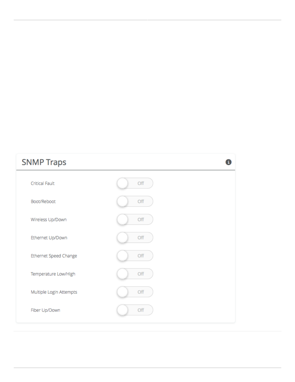
Mimosa Backhaul and B24 Help Content
Mimosa Backhaul Notifications
Copyright © 2018 Mimosa Page Page 61
Configuring SNMP Traps
Define which traps (or notifications) are sent to the remote SNMP server.
Critical Fault - Notification created if the device is forced to reboot.
●
Boot/Reboot - Notification created if the system boots or reboots.
●
Wireless Up/Down - Notification created if the device connects to (Wireless Up) or disconnects from (Wireless
●
Down) another device.
Ethernet Up/Down - Notification created if the Ethernet Port is connected (Ethernet Up) or disconnected
●
(Ethernet Down).
Ethernet Speed Change - Notification created when the Ethernet port changes from one speed (10, 100, or
●
1000BaseT) to another.
Temperature Low/High - Notification created if the temperature falls outside of the safe range for the product.
●
Multiple Login Attempts - Notification created if multiple failed login attempts are made from the same IP
●
Address.
Fiber Up/Down - Notification created when the SFP port is connected (Fiber) or disconnected (Down).
●
Related
SNMP Usage Examples: Get / Walk / Table - Sample commands for retrieving values

Mimosa Backhaul and B24 Help Content
Mimosa Backhaul Notifications
Copyright © 2018 Mimosa Page Page 62
SNMP Object Names - Query values using SNMP Object Names defined within the Mimosa MIB file
SNMP Notifications - Enabling SNMP on Mimosa Backhaul products
SNMP Traps OIDs - OIDs associated with the SNMP Traps
SNMP MIB Download - Available values in standard Management Information Base (MIB) format
SNMP OID Reference - Summarized list of available values and where to find them on the GUI
Mimosa Backhaul and B24 Help Content
Mimosa Backhaul Notifications
Copyright © 2018 Mimosa Page Page 63
SNMP Traps OIDs
Trap Type OID Object Description
Critical Fault Mimosa
Specific
Trap
1.3.6.1.4.1.43356.2.0.1 mimosaCriticalFault Notification created
if the device is
forced to reboot.
Boot/Reboot Standard
Trap
Warm Start:
.1.3.6.1.6.3.1.1.5.2
Cold Start:
.1.3.6.1.6.3.1.1.5.1
snmpColdStart
snmpWarmStart
Notification created
if the system boots
or reboots.
Wireless
Up/Down
Standard
Trap
Up: .1.3.6.1.6.3.1.1.5.4
Down: .1.3.6.1.6.3.1.1.5.3
snmpLinkUp
snmpLinkDown
Notification created
if the device
connects to
(Wireless Up) or
disconnects from
(Wireless Down)
another device.
Ethernet
Up/Down
Standard
Trap
Up: .1.3.6.1.6.3.1.1.5.4
Down: .1.3.6.1.6.3.1.1.5.3
snmpLinkUp
snmpLinkDown
Notification created
if the Ethernet Port
is connected
(Ethernet Up) or
disconnected
(Ethernet Down).
Ethernet
Speed Change
Mimosa
Specific
Trap
1.3.6.1.4.1.43356.2.0.4 mimosaEthernetSpeedChange Notification created
when the Ethernet
port changes from
one speed to
another.
Temperature
Low/High
Mimosa
Specific
Trap
Low:
.1.3.6.1.4.1.43356.2.0.2
High:
.1.3.6.1.4.1.43356.2.0.3
mimosaTempWarning
mimosaTempStatus
Notification created
if the temperature
falls outside of the
safe range for the
product.
Multiple Login
Attempts
Standard
Trap
.1.3.6.1.6.3.1.1.5.5 snmpAuthenticationFailure Notification created
if multiple failed
login attempts are
made from the
same IP Address.

Mimosa Backhaul and B24 Help Content
Mimosa Backhaul Notifications
Copyright © 2018 Mimosa Page Page 64
Related
SNMP Usage Examples: Get / Walk / Table - Sample commands for retrieving values
SNMP Object Names - Query values using SNMP Object Names defined within the Mimosa MIB file
SNMP Notifications - Enabling SNMP on Mimosa Backhaul products
SNMP MIB Download - Available values in standard Management Information Base (MIB) format
SNMP OID Reference - Summarized list of available values and where to find them on the GUI
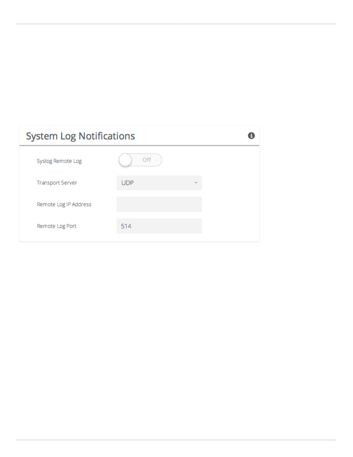
Mimosa Backhaul and B24 Help Content
Mimosa Backhaul Notifications
Copyright © 2018 Mimosa Page Page 65
Enabling System Log Notifications
Enable Syslog service on the local device to send traps to a remote Syslog server.
Syslog Remote Log - Enable or disable Syslog service on the local device.
●
Transport Protocol - Choose the desired protocol for the Syslog connection. Note that most devices send UDP
●
messages by default. UDP is an unreliable transmission protocol, thus messages may get lost. Choose TCP for
higher reliability if any message loss is unacceptable.
Remote Log IP Address - List the IP Address of the remote Syslog server to which Notifications will be sent.
●
Remote Log Port - List the Port on the remote Syslog server to which Notifications will be sent.
●
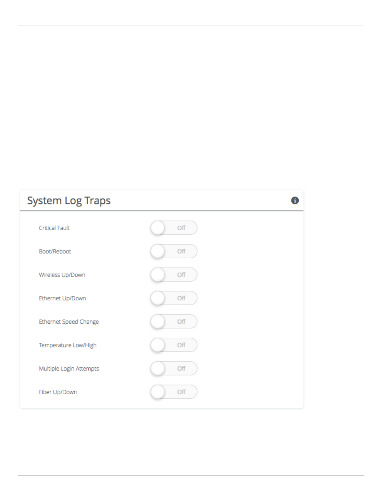
Mimosa Backhaul and B24 Help Content
Mimosa Backhaul Notifications
Copyright © 2018 Mimosa Page Page 66
Configuring System Log Traps
Define which traps (or notifications) are sent to the remote server for the System Log.
Critical Fault - Notification created if the device is forced to reboot.
●
Boot/Reboot - Notification created if the system boots or reboots.
●
Wireless Up/Down - Notification created if the device connects to (Wireless Up) or disconnects from (Wireless
●
Down) another device.
Ethernet Up/Down - Notification created if the Ethernet Port is connected (Ethernet Up) or disconnected
●
(Ethernet Down).
Ethernet Speed Change - Notification created when the Ethernet port changes from one speed (10, 100, or
●
1000 BaseT) to another.
Temperature Low/High - Notification created if the temperature falls outside of the safe range for the product.
●
Multiple Login Attempts - Notification created if multiple login attempts are made from the same IP Address.
●
Fiber Up/Down - Notification created when the Fiber port is connected (Fiber) or disconnected (Down).
●
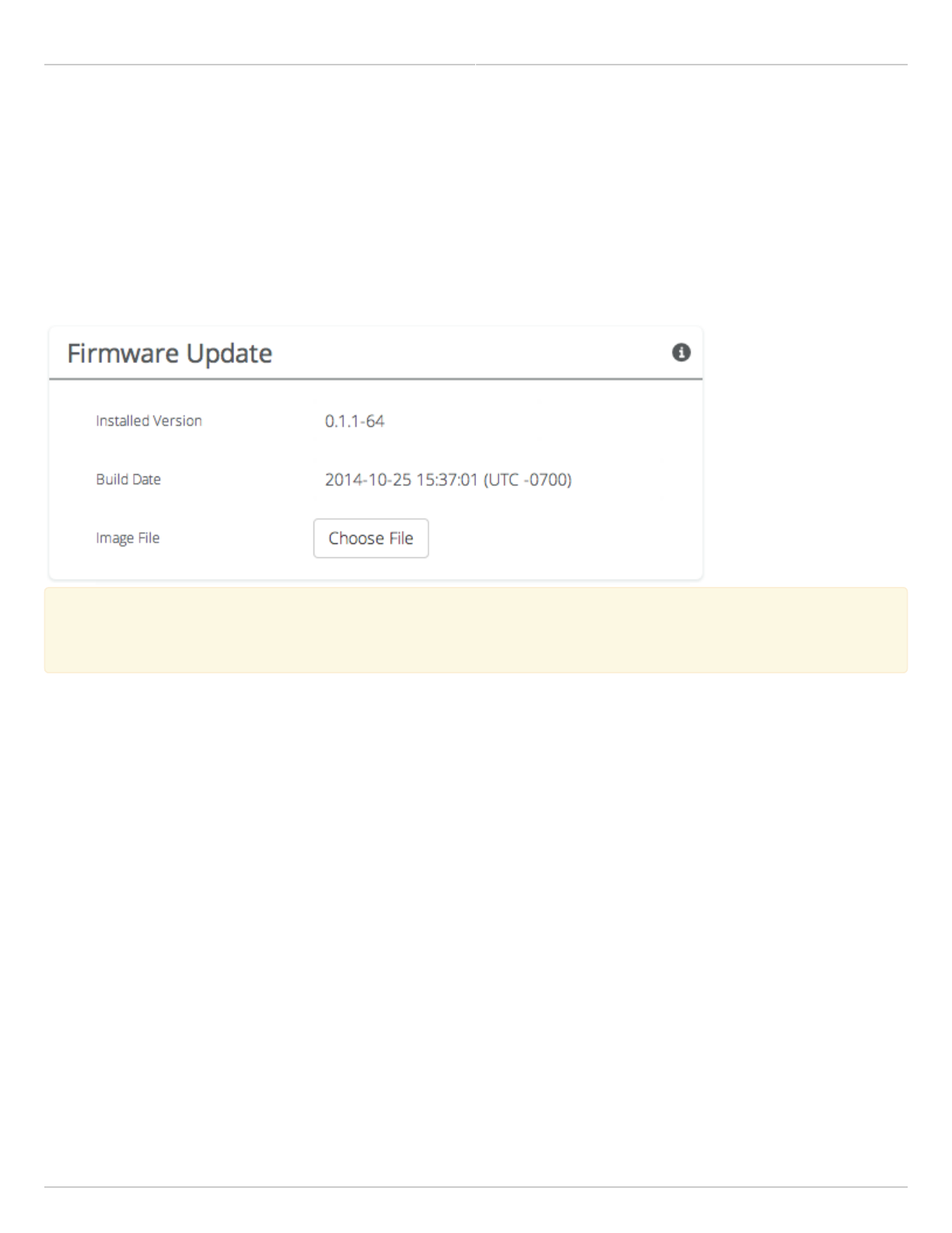
Mimosa Backhaul and B24 Help Content
Mimosa Backhaul Firmware & Reset
Copyright © 2018 Mimosa Page Page 67
Performing a Firmware Update
The Firmware Update panel displays the current firmware version and date, and allows the user to upload a new
firmware image. The latest firmware image may be downloaded from help.mimosa.co. Alternately, firmware can be
pushed to the device automatically through the Manage application at manage.mimosa.co.
Installed Version - The currently installed firmware version.
●
Build Date - The date that the installed firmware was created.
●
Image File - Update to the latest firmware. Click the Choose File button to select a file for upload the file.
●
When performing a Firmware upgrade, it is advisable to reboot and then upgrade the remote side of the
When performing a Firmware upgrade, it is advisable to reboot and then upgrade the remote side of the
link before the local side. If there is a problem during the upgrade you will still have access to one of the
link before the local side. If there is a problem during the upgrade you will still have access to one of the
radios within the link and can manage the link details.
radios within the link and can manage the link details.
The firmware update process occurs in four phases:
Upload - Selecting a firmware image and uploading to the radio1.
Verification - Ensuring that the firmware image is complete and without errors2.
Upgrade - Writing the new firmware image to flash memory3.
Reboot - Restarting with the new firmware image (120 seconds)4.
Once the remote radio enters the Upgrade phase, it is generally safe to begin the Upload phase to the local radio.
Alternately, the Mimosa Manage application offers a parallel upgrade feature which sends the firmware image to
both radios, and once both radios receive and verify the image, they upgrade at the same time and reboot in an
order that you specify.
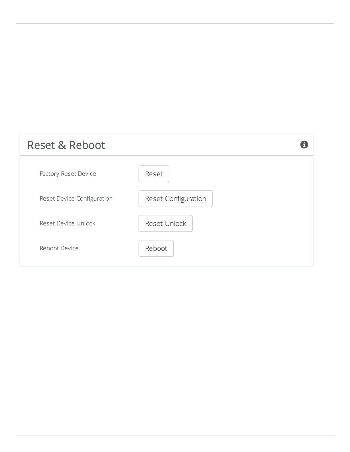
Mimosa Backhaul and B24 Help Content
Mimosa Backhaul Firmware & Reset
Copyright © 2018 Mimosa Page Page 68
Reset & Reboot the Device
Reboot the device or reset it to its original factory settings.
Factory Reset Device - Clears all configuration settings and locks the device. WARNING: This will delete ALL
●
saved configuration settings and return the device to the locked factory state. You will be required to re-enter
your unlock key upon device reset. The current version of firmware will remain, however.
Reset Device Configuration - Clears all configuration settings. The device will remain unlocked.
●
Reset Device Unlock - Locks the device and resets the country code. WARNING: You will be required to re-enter
●
your unlock key upon reset.
Reboot Device - Restarts the device.
●
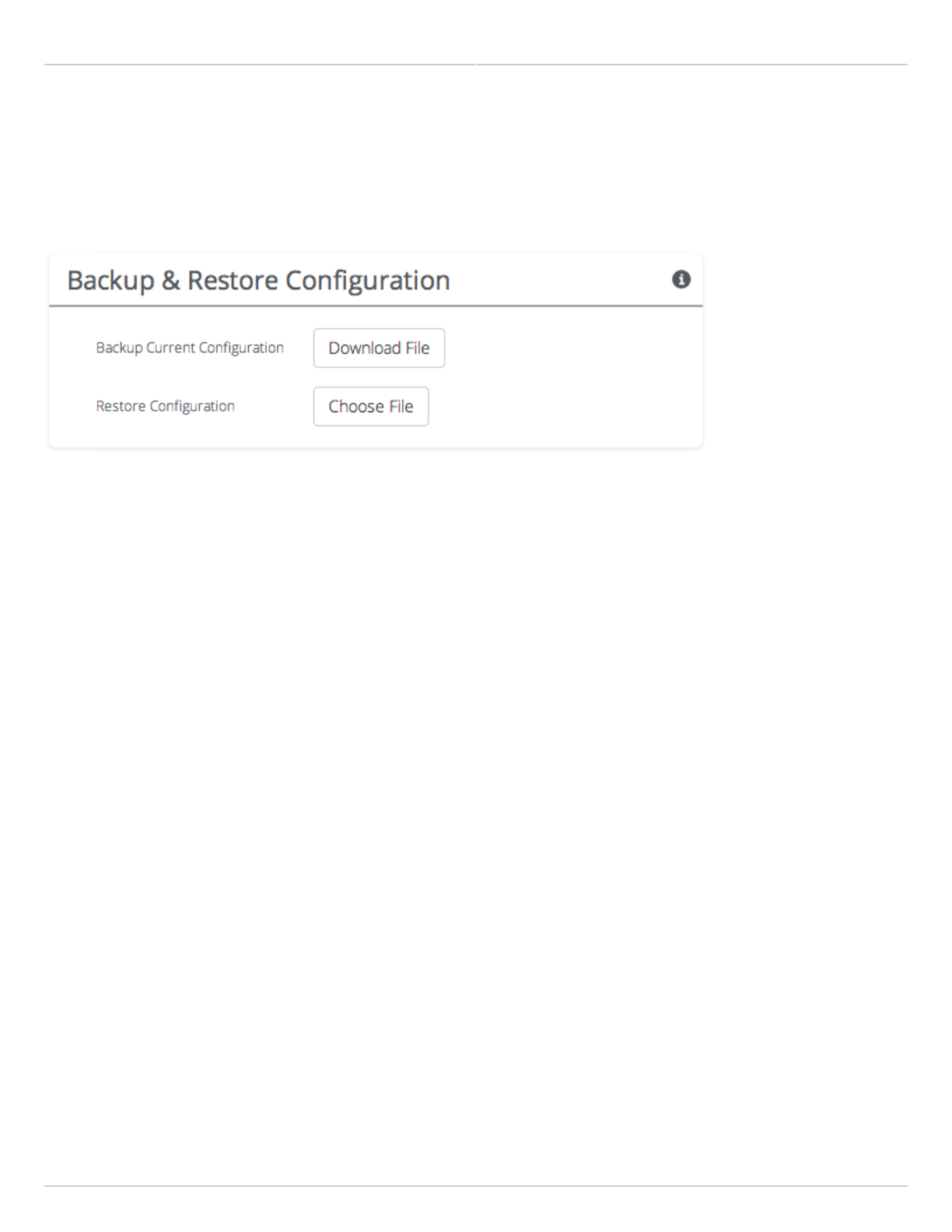
Mimosa Backhaul and B24 Help Content
Mimosa Backhaul Backup & Restore
Copyright © 2018 Mimosa Page Page 69
Backup or Restore Configuration Settings
The Backup and Restore Configuration panel contains controls for managing configuration settings files.
Backup Current Configuration - Perform a configuration backup by downloading the mimosa.conf file.
●
Restore Configuration - Click the Choose File button to upload a previously saved mimosa.conf file.
●

Mimosa Backhaul and B24 Help Content
Mimosa Backhaul Tests
Copyright © 2018 Mimosa Page Page 70
Diagnostic Tests
Three types of tests are available within the Diagnostics section: Ping, Bandwidth and Traceroute.
Ping Test
A low level ICMP test which indicates whether the target host is reachable from the local device.
Destination Host - The destination IP Address of the device to ping.
●
Packet Count - The number of packets to transmit during a ping.
●
Packet Size (bytes) - The size of each packet to transmit during a ping.
●
Run Test - Click on the Run Test button to ping the destination IP address. Results are shown in the
●
corresponding table.
Bandwidth Test
A manual test to assess maximum throughput when minimal or no traffic is present. This test sends 1500-byte
packets using a proprietary UDP-like protocol. Results are shown in corresponding graph on this page. Note that
bandwidth test data is excluded from the Dashboard Performance graph. This is because the test is conducted by
transmitting packets at a low layer between the two radios. Navigating away from this page will stop the test.
Test Duration - The length of the bandwidth test in seconds.
●
Test - Select one of the following options to assess the maximum throughput:
●
Local to Remote - Unidirectional test from the local device to the remote device
●
Remote to Local - Unidirectional test from the remote device to the local device
●
Transmit then Receive - Bidirectional tests conducted in series
●
Simultaneous - Bidirectional test conducted in parallel
●
Traceroute Test
A network utility used to display the path and transit delay between the local device and a given destination across
an IP network.
Destination Host - The destination IP address for traceroute to send packets.
●
Resolve IP Address - Indicate whether the system should resolve and print the host name of the destination.
●
Max Number of Hops - Choose the maximum number of intermediate devices (e.g. routers) through which
●
packets must pass between source and destination.
Run Test - Click on the Run Test button to begin the traceroute test. Results are shown in the corresponding
●
table.
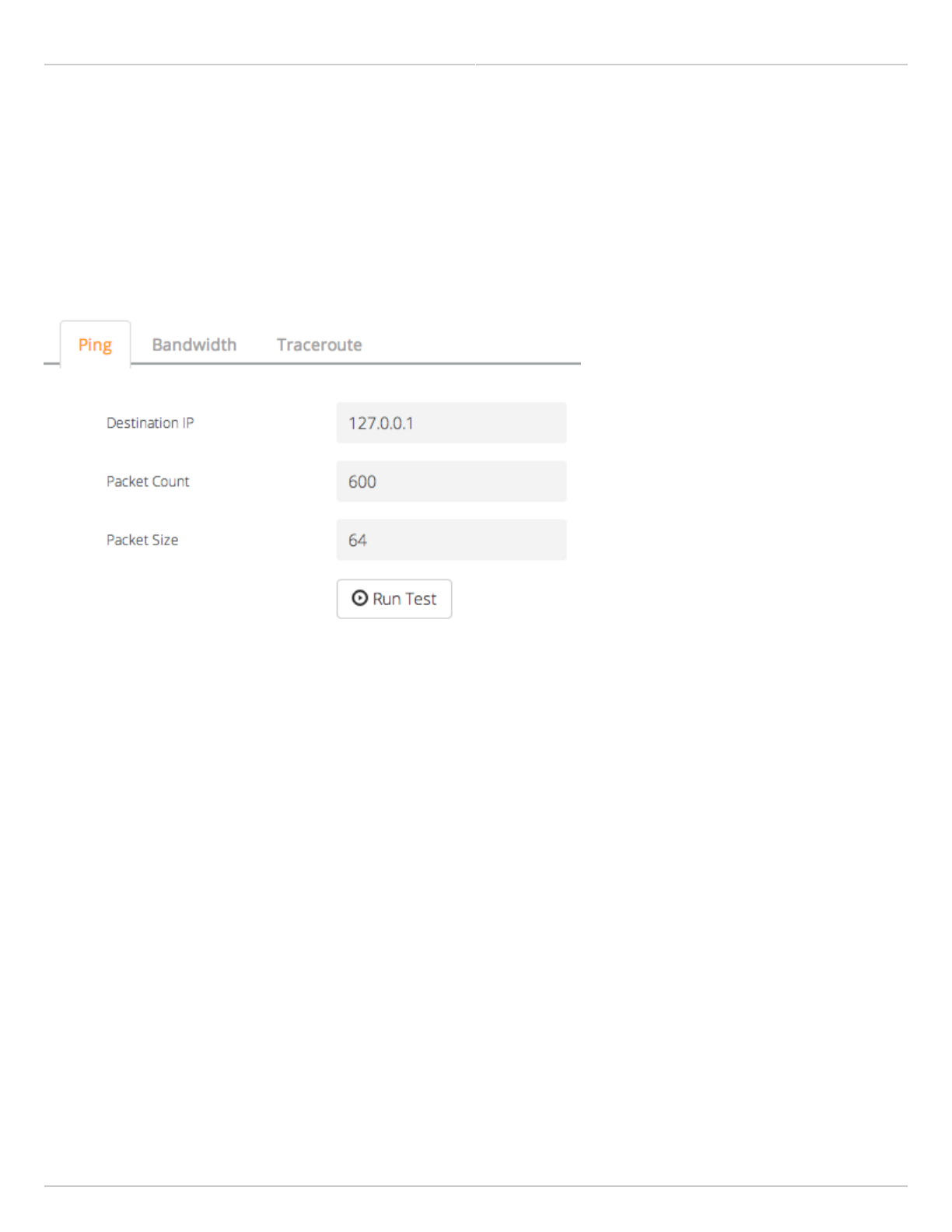
Mimosa Backhaul and B24 Help Content
Mimosa Backhaul Tests
Copyright © 2018 Mimosa Page Page 71
Running a Ping Test
A low level ICMP test which indicates whether the target host is reachable from the local device.
Destination Host - The destination IP Address of the device to ping.
●
Packet Count - The number of packets to transmit during a ping.
●
Packet Size (bytes) - The size of each packet to transmit during a ping.
●
Run Test - Click on the Run Test button to ping the destination IP address. Results are shown in corresponding
●
table.
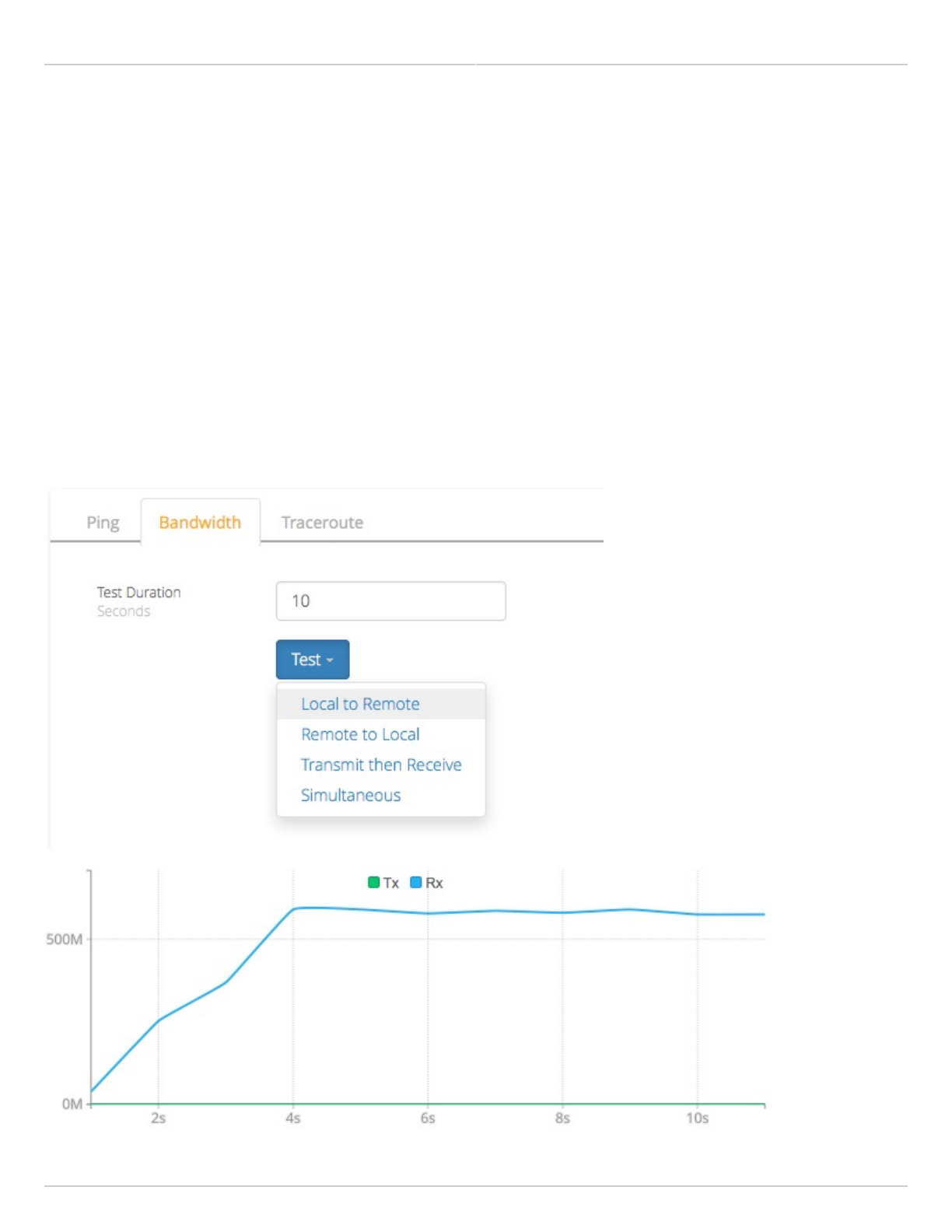
Mimosa Backhaul and B24 Help Content
Mimosa Backhaul Tests
Copyright © 2018 Mimosa Page Page 72
Running a Bandwidth Test
A manual test to assess maximum throughput when minimal or no traffic is present. This test sends 1500-byte
packets using a proprietary UDP-like protocol. Results are shown in corresponding graph on this page. Note that
bandwidth test data is excluded from the Dashboard Performance graph. This is because the test is conducted by
transmitting packets at a low layer between the two radios. Navigating away from this page will stop the test. The
bandwidth test is only available when devices are associated in PTP mode.
Test Duration - The length of the bandwidth test in seconds.
●
Test - Select one of the following options to assess the maximum throughput:
●
Local to Remote - Unidirectional test from the local device to the remote device
●
Remote to Local - Unidirectional test from the remote device to the local device
●
Transmit then Receive - Bidirectional tests conducted one after the other
●
Simultaneous - Bidirectional test conducted at the same time
●
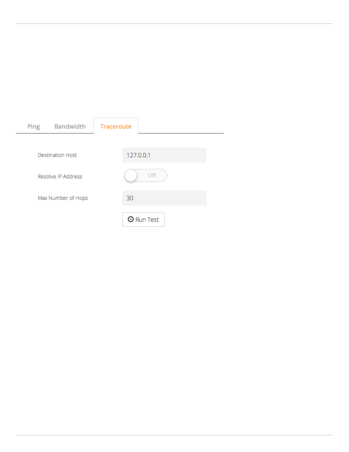
Mimosa Backhaul and B24 Help Content
Mimosa Backhaul Tests
Copyright © 2018 Mimosa Page Page 73
Running a Traceroute Test
A network utility used to display the path and transit delay between the local device and a given destination across
an IP network.
Destination Host - The destination IP address for traceroute to send packets.
●
Resolve IP Address - Indicate whether the system should resolve and print the host name of the destination.
●
Max Number of Hops - Choose the maximum number of intermediate devices (e.g. routers) through which
●
packets must pass between source and destination.
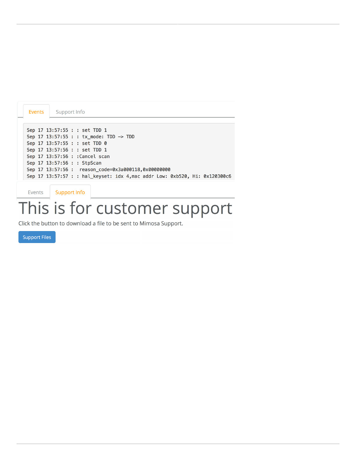
Mimosa Backhaul and B24 Help Content
Mimosa Backhaul Logs
Copyright © 2018 Mimosa Page Page 74
Diagnostic Logs
View Events and download diagnostic information to share with Mimosa Support.
Event Log - This is a persistent (non-volatile) log of all significant events that occur.
●
Support Info - Download a single file containing all information required by Mimosa Support to help with
●
troubleshooting.
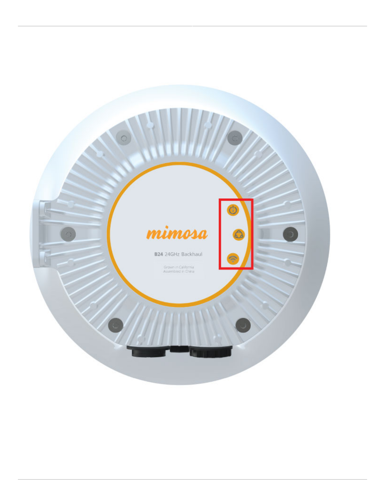
Mimosa Backhaul and B24 Help Content
Mimosa Backhaul LED Status Indicators
Copyright © 2018 Mimosa Page Page 75
B24 External LED Status Indicators
Three LED indicators on the outside of the case communicate operational status: Power, Ethernet, and Wireless.
The tables below describe the meaning of each LED's state: Off, On (solid), On (blinking), and Color.
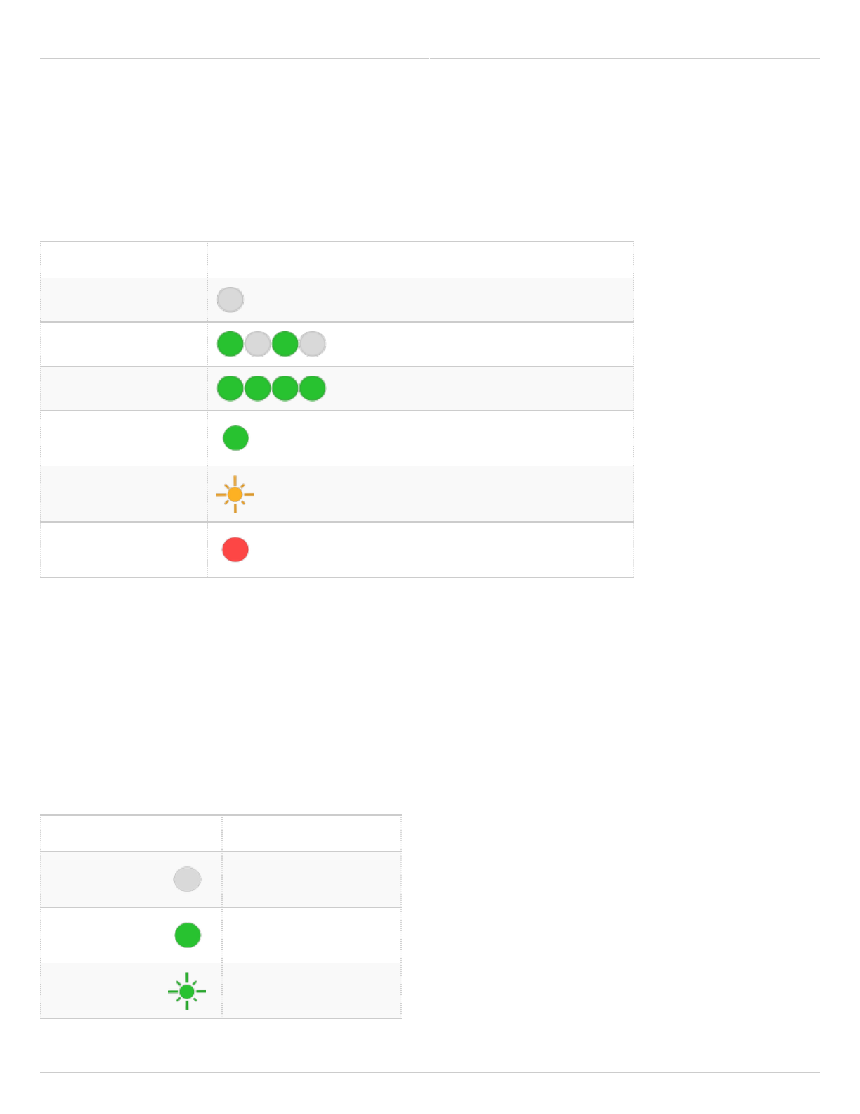
Mimosa Backhaul and B24 Help Content
Mimosa Backhaul LED Status Indicators
Copyright © 2018 Mimosa Page Page 76
Power Status LED Table
The Power Status LED indicates the presence of power, and communicates boot and firmware update status.
State LED Description
Off No Power to Device
Blinking Green (Slow) Device Booting / Rebooting
Blinking Green (Fast) Firmware Update in Progress
Solid Green Ready (Operational)
Blinking Yellow Update Failed (Invalid Firmware Image)1
Solid Red Wiring Error or Boot Error2
1 Please visit the Firmware page to download the latest image.
2 Please check wiring, cycle power, and then contact Mimosa Support if necessary.
Ethernet Status LED Table
The Ethernet Status LED indicates the negotiated port speed for the wired network connection. The device is
designed to perform best with a 1000BASE-T connection. While other port speeds are possible, they are not
recommended because they create a data bottleneck that reduces end-to-end throughput.
State LED Description
Off No Ethernet Connection
Solid Green 1000BASE-T
Blinking Green 1000BASE-T with Traffic
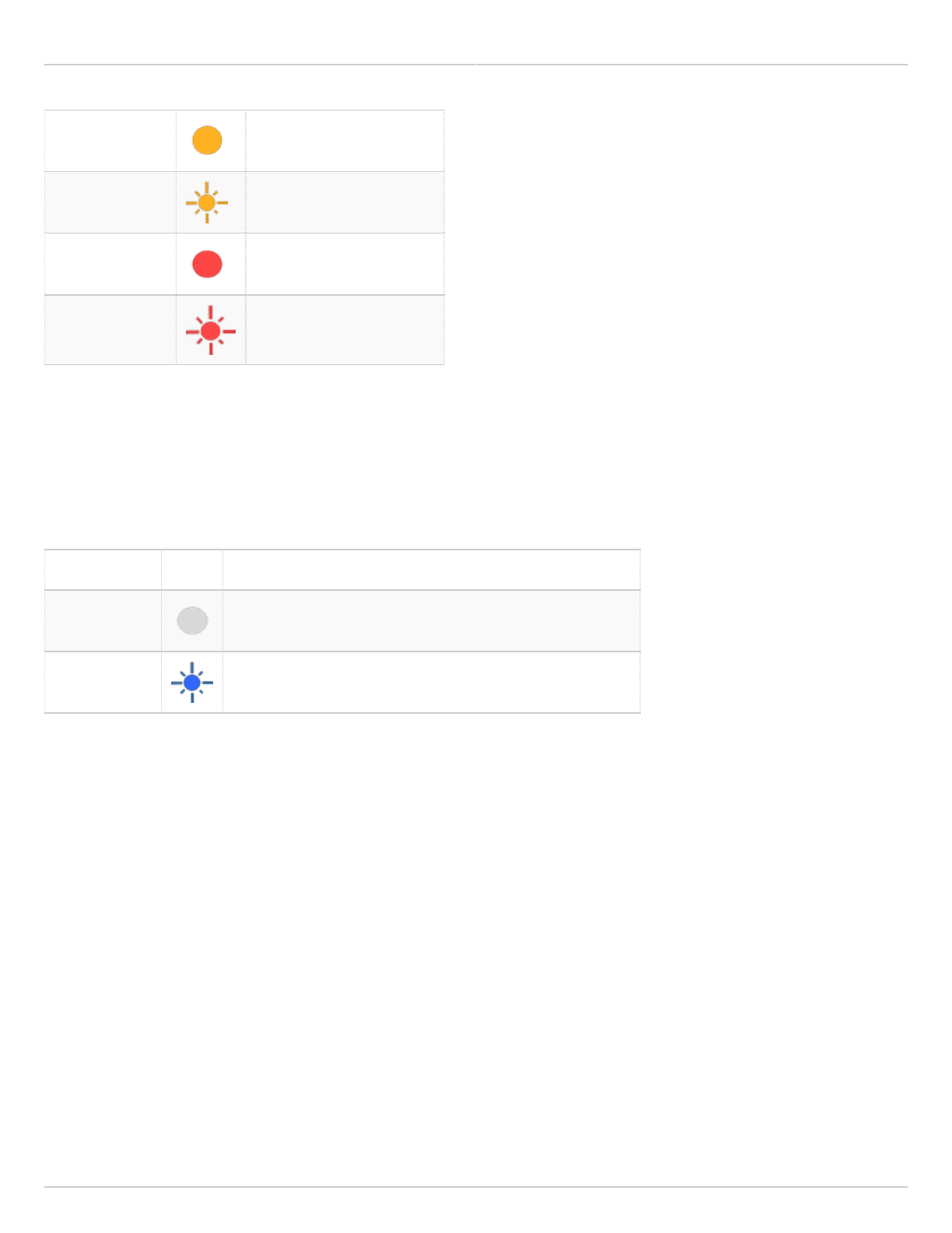
Mimosa Backhaul and B24 Help Content
Mimosa Backhaul LED Status Indicators
Copyright © 2018 Mimosa Page Page 77
Solid Yellow 100BASE-T
Blinking Yellow 100BASE-T with Traffic
Solid Red 10BASE-T
Blinking Red 10BASE-T with Traffic
Wireless Status LED Table
The Wireless Status LED indicates a link between local and remote devices. The blink rate represents received signal
strength, which is useful while aiming the local device.
State LED Description
Off Not Associated (No Link)
Blinking Blue Associated; Blink rate proportional to signal strength*
* Ranges from 1 Hz (one blink per second at -90 dBm or less) to 10 Hz (one blink per 100 ms at -50 dBm or greater).