Mimosa Networks 100-00033 2.4 GHz Wi-Fi PoE Gateway User Manual G2 Revised 0420
Mimosa Networks, Inc. 2.4 GHz Wi-Fi PoE Gateway G2 Revised 0420
User manual

Product Requirement Specification
Mimosa Confidential Page
1
2.4 GHz Wi-Fi PoE Gateway
User manual

Product Requirement Specification
Mimosa Confidential Page
2
Revision History
Version Date Authors Comments
1.0 6/24/2015 LiteOn, Reza,
David Stiff
Final 1.0 after Mimosa and LiteOn
final review. Note: This is a living
document and will be updated as
product development proceeds.
Author: LiteOn, Reza Reviewed and Approved by:
LiteOn: Stanley Wang (6/24/15)
Mimosa: David Stiff, Reza Golshan (6/24/15)
Editor: David Stiff Project Leader: Reza Golshan
Approval:
Vice President, Product Management
Mimosa Networks, Inc.
6/25/15
(For Confirming the Spec Only, not an Official Agreement for
OEM/ODM Business)
© Copyright 2014 by Mimosa Networks, Inc. All rights reserved. Other product and company names mentioned herein may be the trademarks of their
respective owners.
<Part Number>

Product Requirement Specification
Mimosa Confidential Page
3
Table of Contents
1Product Overview ................................................................................................................................................. 4
1.1Deployment Applications...........................................................................................................................5
1.2Operational Description& Modes..............................................................................................................6
2Deliverables ........................................................................................................................................................... 8
3Hardware requirements ...................................................................................................................................... 9
3.1Main Components......................................................................................................................................9
3.2Wired Networking Interfaces....................................................................................................................9
3.3Wireless Interface......................................................................................................................................9
3.4Wireless Interface RF Performance........................................................................................................10
3.5Other Interfaces.......................................................................................................................................11
3.6Power Supply............................................................................................................................................11
3.7PCB Structure...........................................................................................................................................12
3.8Enclosure and Mechanical........................................................................................................................13
3.9LED Indicators..........................................................................................................................................17
3.10Reset Button............................................................................................................................................18
4SW Features ........................................................................................................................................................ 19
5Environmental ..................................................................................................................................................... 28
6Reliability ............................................................................................................................................................. 29
7Regulatory and Certifications ........................................................................................................................... 30

Product Requirement Specification
Mimosa Confidential Page
4
1 Product Overview
The POE Wi-Fi Router is a wall wart plug-in wireless access point with full
router and multi-mode operational capabilities. It has two GigE ports one for
WAN and one for LAN interface. The WAN port has as a POE injector (passive)
for connecting to Mimosa devices (C5/C5c/C5i). It can be configured as a Wi-
Fi Router, Wi-Fi Extender, Range Extender, or POE pass-through. It has the
features as follows:
xAutomated configuration from Mimosa Cloud NMS
xBuilt in 2.4GHz 802.11b/g/n 2x2:2 wireless AP with integrated antenna
xTwo GigE (10/100/1000BaseT) Interface, WAN & LAN
xPOE output for WAN –passive PSE 48V/10W
xInterchangeable AC clips to deploy in different countries
x4 modes of operation: Wi-Fi Router, Wi-Fi Extender, Range Extender,
or POE pass-through
xNAT Routing (DHCP, SPI, Port Forwarding)
xPPPoE and PPTP support
xRate Limiting
xUp to 4 SSIDs
xGuest Network SSID
Product Requirement Specification
Mimosa Confidential Page
5
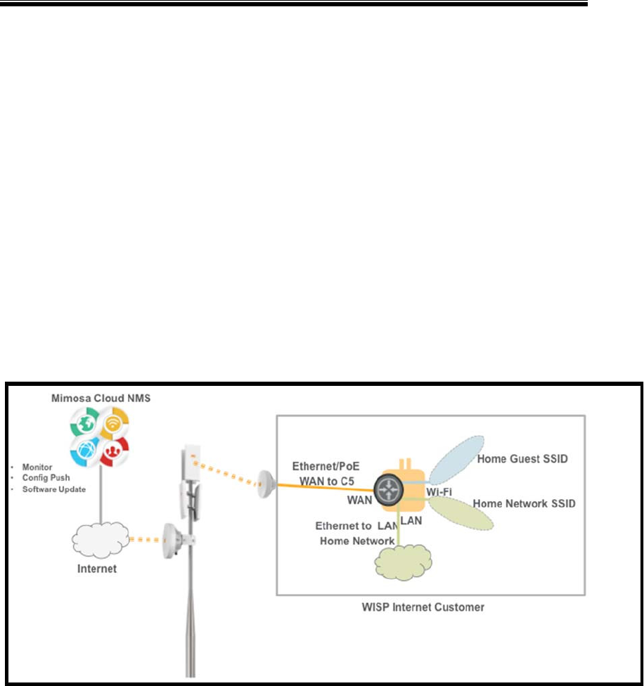
1.1 Deployment Applications
The deployment model of the PoE Wi-Fi Router is to provide the in-home,
“final leg” portion of a Mimosa fixed wireless solution typically deployed by
Wireless Internet Service Providers (WISPs). It provides the necessary WAN
routing, Wi-Fi and LAN connections to bring the Internet into the home. It’s
designed to be part of a complete Mimosa solution that provides easy
installation and automated configuration from the Mimosa Cloud NMS. It
simply plugs into a wall outlet and has a color-coded Mimosa jack to indicate
which port is connected to the Mimosa CPE device. It is only designed to
provide PoE power to Mimosa C5/C5c/C5i CPE devices.
Product Requirement Specification
Mimosa Confidential Page
6
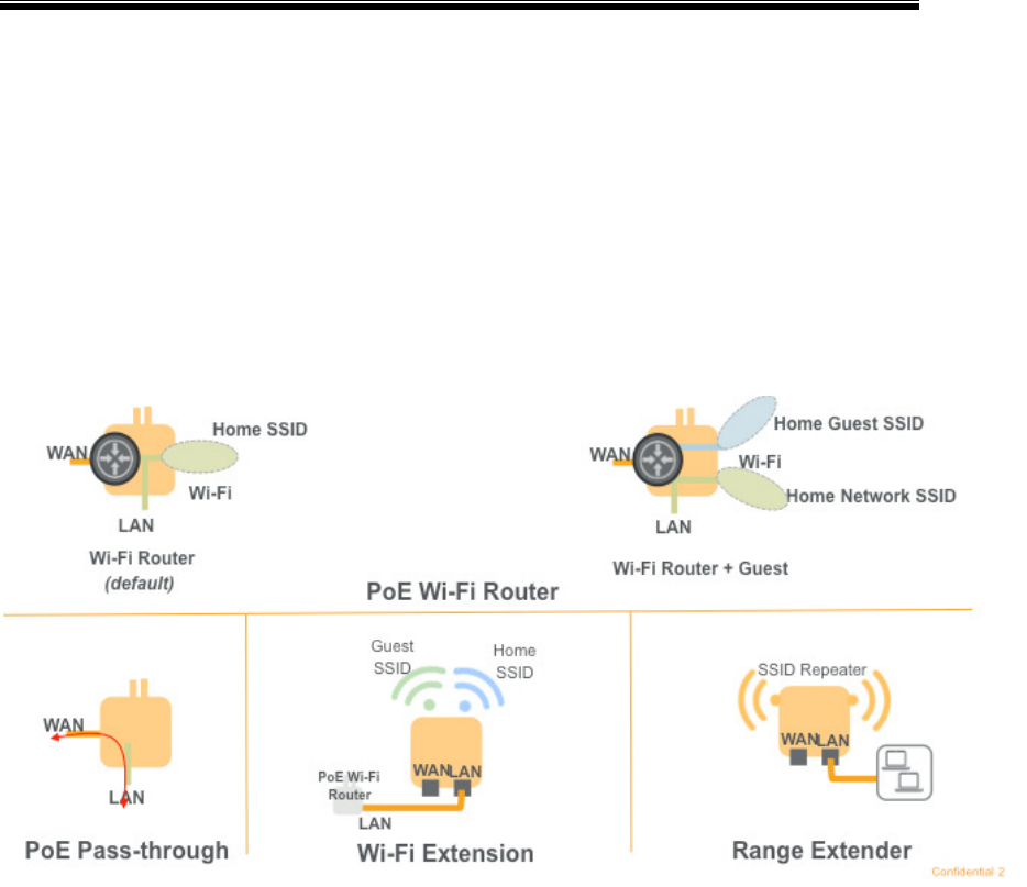
1.2 Operational Description& Modes
The advanced PoE Wi-Fi Router is designed to be used inside a home/small
office to provide PoE power to a Mimosa C5, C5c or C5i CPE wireless device
and Internet connectivity via Wi-Fi and a LAN connection. There are 4
operational modes that provide the following features and function:
xPoEWi-Fi Router: This mode powers the Mimosa C5/C5c/C5i CPE and
provides everything needed for in-home Internet access via Wi-Fi or
LAN. Power to the Mimosa CPE is provided via PoE on the WAN port
using passive PSE 48V/10W. Network and routing servicesfor NAT,
DHCP, stateful packet inspection, and port forwarding provide Internet
connectivity to the home network. The Home network is provided by a
2.4 GHz 802.11n Wi-Fi access point supporting up to 4 SSIDs including
Guest Access and a Gigabit LAN connection.
xPoE Pass-through: This mode is used when a 3rd party Wi-Fi/WAN
Router is installed. When inPoE Pass-Through mode the PoE Wi-Fi
Router disables the routing and Wi-Fi operations and simply provides
PoE power and bridging between the WAN and LAN ports.
xRange Extender: The Range Extension, or repeater, mode is designed
for increasing Wi-Fi coverage to a location where the in-house main
router's signal is very weak or doesn't reach at all. It takes the radio
Product Requirement Specification
Mimosa Confidential Page
7
signal form the in-house main router and rebroadcasts it to create a
second network (it receives, then retransmits each packet using the
same radio on the same channel and with the same SSID.). It bridges
the gap between the main router and the second network. The
throughput loss will be more than 50%.
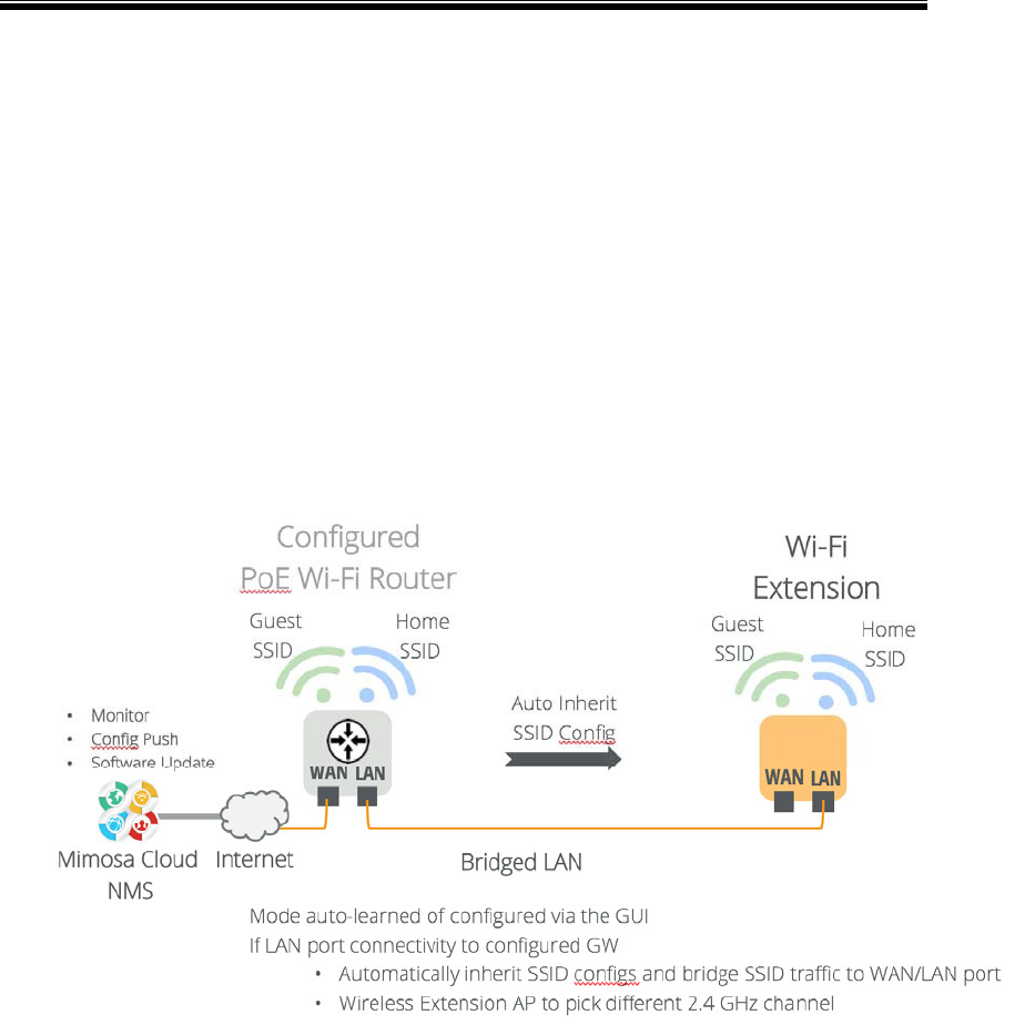
xWi-Fi Extender: This mode is designed to extend the reach of Wi-Fi for
homes/small offices with in-house LAN wiring. Adding a second PoE
Wi-Fi Router in “Wi-Fi Extender” mode allows you to increase Wi-Fi
coverage without sacrificing performance. When installed, it
automatically learns the SSID from the primary device and extended
Wi-Fi coverage using a different channel.
Product Requirement Specification
Mimosa Confidential Page
8
2 Deliverables
xThe Plug-In Wi-Fi Router with PoE and embedded software
xUser Documentation
oQuick Start Guide
oWarranty/SLA
oRegistration card
oRegulatory flyer
xRJ45 blocker (installed into RJ45 connector)
xLiteOn-designed brown box
xMimosa-design giftbox (covering over brown box)
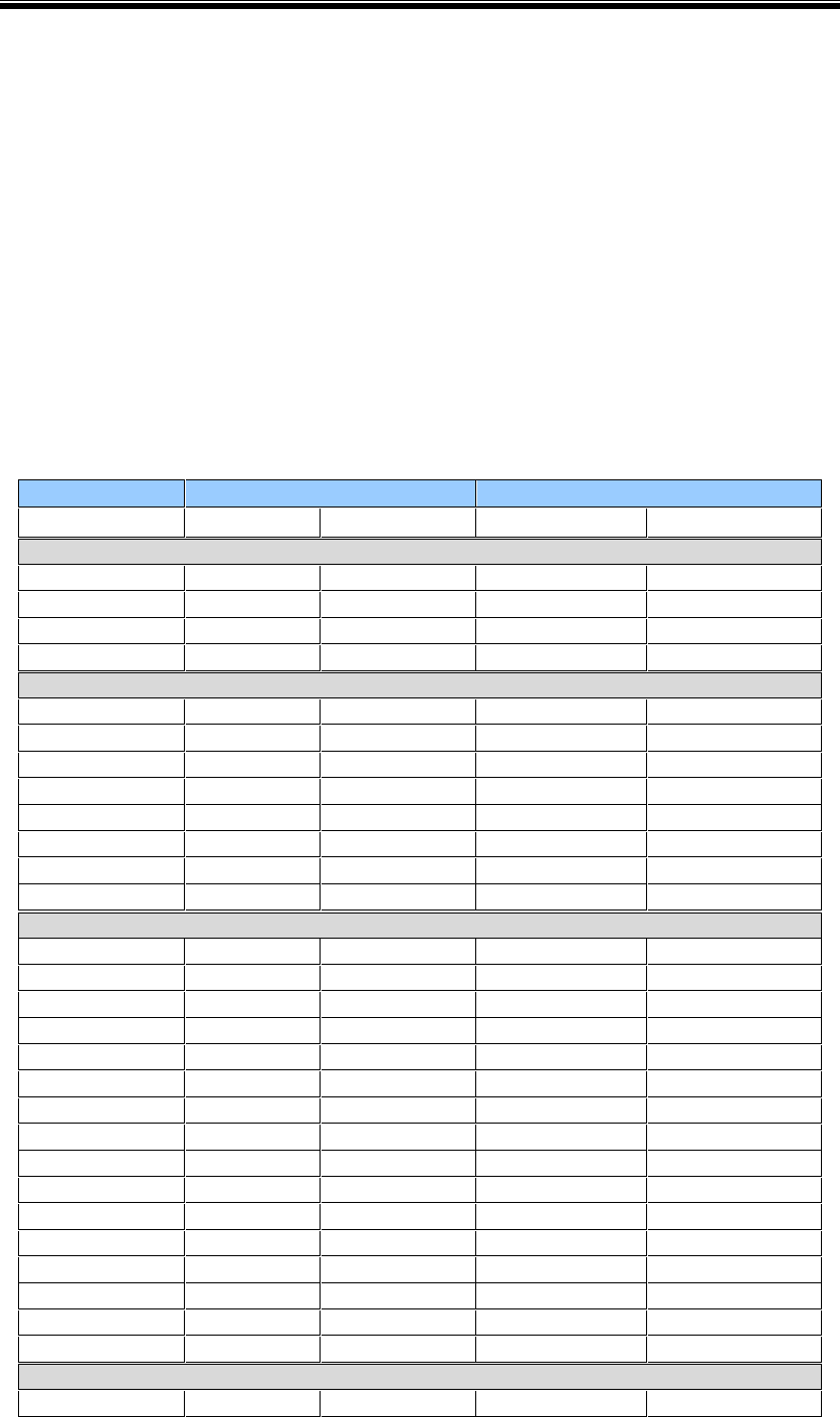
xOne clip to each correspong SKU
totally 4 SKUs
Country Type
USA, Canada, Mexico, and Japan Type A
Europe, and Russia (except UK & Ireland) Type C
UK, Ireland, Malta, Malaysia & Singapore
Type G (plastic
ground)
Australia, New Zealand,
Type I – 2 pin
(insulated)

Product Requirement Specification
Mimosa Confidential Page
9
3 Hardware requirements
3.1 Main Components
xProcessor: MT7620A
oMIPS24KEc (580 MHz) with 64KB I-cache, 32KB D-cache
o2.4GHz 802.11 b/g/n 2T×2R, 2 spatial streams
xFlash: 8MB SPI NOR
oSDRAM: 64MB 16-bit DDR2
xPoE non-standard passive PSE on WAN port at 10W
3.2 Wired Networking Interfaces
x2xRJ45
o1x10/100/1000BaseT LAN
o1×10/100/1000BaseT PoE PSE WAN port,
oPoE non-standard passive PSE on WAN port at 10W
3.3 Wireless Interface
xIEEE802.11 b/g/n
x2.4GHz, 2T2R, 2 Spatial Streams MIMO
x300Mbps Phy data rate
xSupports Reverse Data Grant (RDG), Maximal Radio Combing (MRC),
Space Time Block Coding (STBC)
xFrequency Range: 2.4GHz~2.484GHz
xData Rate:
o802.11b: 1,2,5.5,11Mbps
o802.11g: 6,9,12,18,24,36,48,54 Mbps
o802.11n: MCS0~MCS15, 6.5,13,19.5,26,39,52,58.5,65,150,300
Mbps
xAntenna:
oTwo orthogonally polarized antennas; mounted internally. A
single dual polarized antenna is not specifically excluded.
Product Requirement Specification
Mimosa Confidential Page
10
oAntenna Gain: -4dBi or higher over 60% of all directions.
Typically omnidirectional pattern, intended to radiate into a
room or through a wall behind the device.
oFrequency of operation at least as wide as paragraph 2.4 (above)
oBoth antennas shall not have nulls in the same direction
os11 shall be -10dB or less over the operating frequency band
oVarious types of antennas may be considered with minimal cost
being a primary concern; consequently antennas integrated into
the PCB are preferable.
3.4 Wireless Interface RF Performance
LiteOn Mimosa
Tx (+/- 2dB) Rx+/- 2dB Tx Rx
802.11b
1 Mbps 16 -93
2 Mbp 16 -90
5.5 Mbps 15 -90
11 Mbps 15 -86 -80
802.11g
6 Mbps 16 -88
9 Mbps 16 -86
12 Mbps 16 -85
18 Mbps 16 -84
24 Mbps 15 -82
36 Mbps 15 -78
48 Mbps 14 -74
54 Mbps 14 -72 -72
802.11n 20HT
MCS0 16 -88
MCS1 16 -86
MCS2 16 -85
MCS3 16 -80
MCS4 15 -78
MCS5 15 -75
MCS6 13 -73
MCS7 13 -71 -67
MCS8 16 -87
MCS9 16 -85
MCS10 16 -82
MCS11 16 -78
MCS12 15 -76
MCS13 15 -72
MCS14 13 -70
MCS15 13 -69
802.11n 40HT
MCS0 15 -84

Product Requirement Specification
Mimosa Confidential Page
11
MCS1 15 -83
MCS2 15 -82
MCS3 15 -77
MCS4 14 -75
MCS5 14 -72
MCS6 12 -70
MCS7 12 -68 17(aggregated) -66
MCS8 15 -82
MCS9 15 -81
MCS10 15 -79
MCS11 15 -75
MCS12 14 -73
MCS13 14 -70
MCS14 12 -68
MCS15 12 -66
3.5 Other Interfaces
xConsole: 4-pin pin header UART
xGPIO Test Points
3.6 Power Supply
xAC to DC Converter
oInput Voltage: 100~240VAC, 50/60Hz
oInput Current: 0.6A (RMS)@ 120VAC, 0.4A (RMS)@240VAC
oInrush Current: <60A (RMS) Peak @120VAC, <120A (RMS)
Peak@240VAC
oOver Current Protection, Over Voltage Protection
oOutput Voltage: 48VDC +/-5%, 12V +/-4V
oOutput Current: 48V/210mA, 12V/330mA (10Watts for PoE PSE,
4Watts for main board)
oEfficiency: Typ >75.9%
oRipple Voltage: 200mV P-P
oPassive non standard PoE to PoE PSE WAN port
xInterchangeable AC Clip
Country Type
USA, Canada, Mexico, and Japan Type A
Product Requirement Specification
Mimosa Confidential Page
12
Europe, and Russia (except UK & Ireland) Type C
UK, Ireland, Malta, Malaysia & Singapore
Type G (plastic
ground)
Australia, New Zealand,
Type I – 2 pin
(insulated)
Note:
I. For the EU plug type, need the CEE 7/16
II. For type I socket to cover all countries we require
insulated per Australia standard.
III. Surfacefinish:VDINo.36
3.7 PCB Structure
xTwo PCBs – power board and main board
Product Requirement Specification
Mimosa Confidential Page
13
xThe connection bewteen the power board and the main board are two
1x4 pin headers(one for 48VDC, another for 12VDC)
3.7.1 Power Board
xAC to 48VDC/12VDC Converter
xPCB Dimensions: 83.5mm x 47.5mm x 1mm
xTwo 1x4 pin receptacle connector to connect to the main board
xTwo pads for interchangeable AC Clips
3.7.2 Main Board
xAll circuit except AC/DC converter are on this board
xPCB dimensions: 83.5mm x 47.5mm x 1mm
xTwo 1x4 pin header connectors to connect to the power board
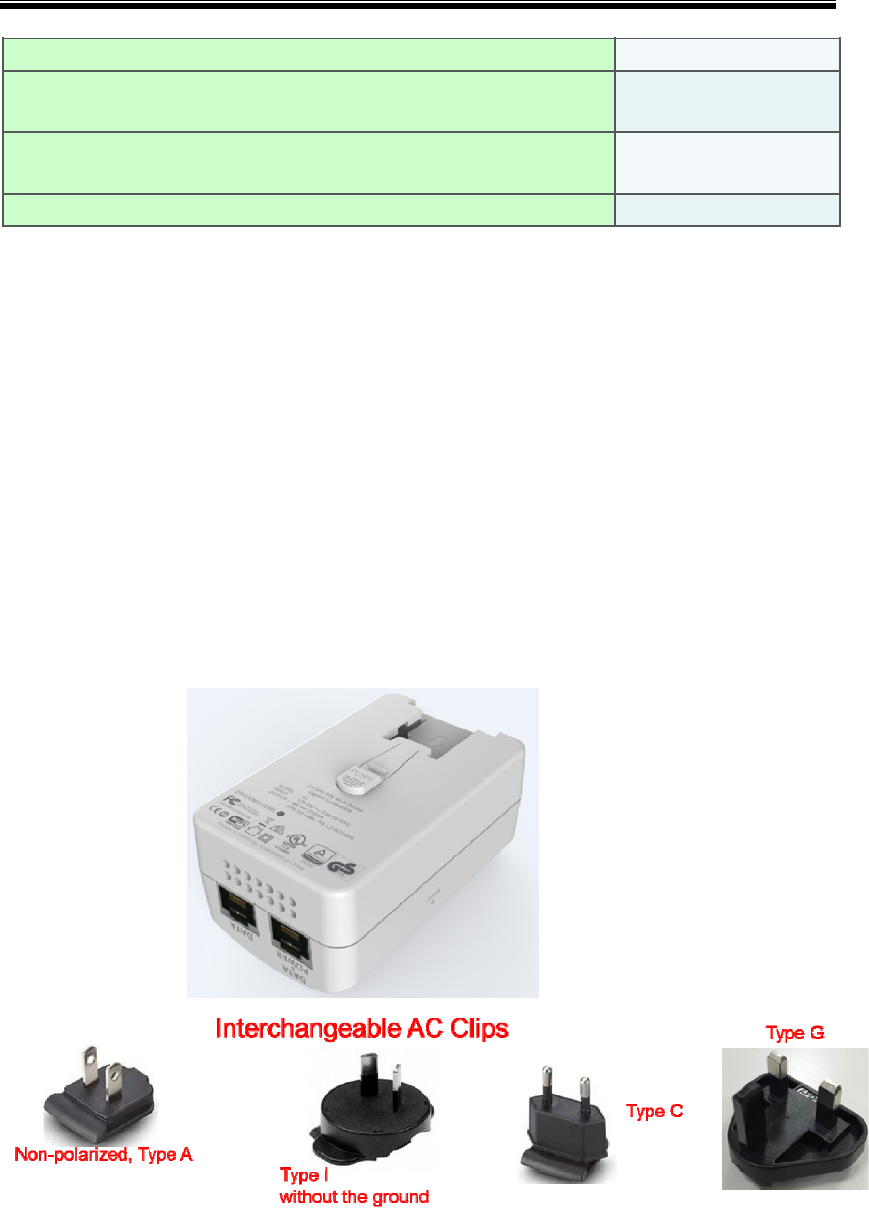
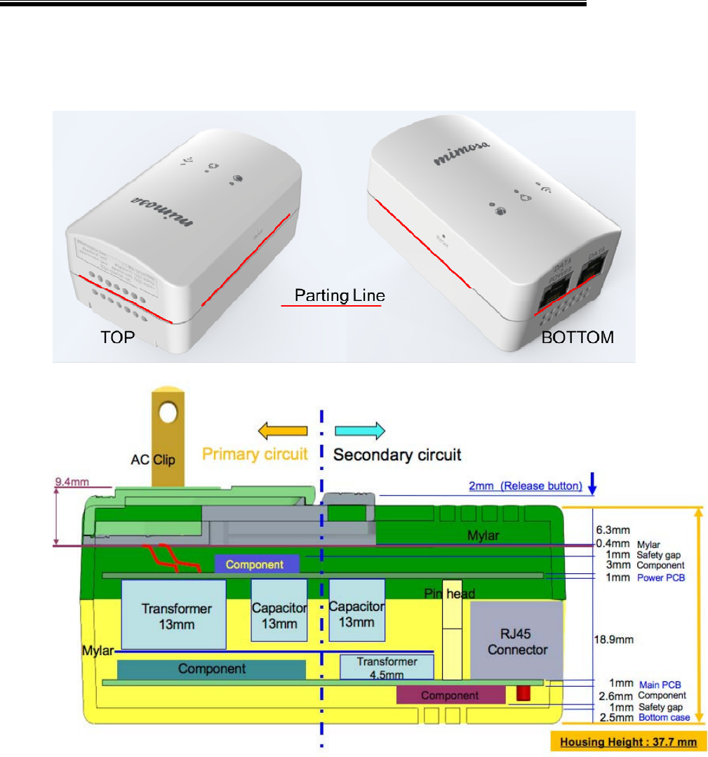
3.8 Enclosure and Mechanical
xME Dimenson : 92mm(L)x57mm(W)x42 mm(H): (Refer to Industrial
Design Surfaces).
x
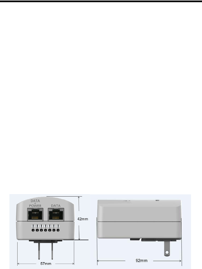
xProduct ME Dimensions NOTE: Color is not accurate
xPlastics should match Sabic Lexan 945 PN/8T9D355. The next few
pictures illustrate the shape and finish of the final product. See CAD
files for exact dimensions.
Product Requirement Specification
Mimosa Confidential Page
14
xScratches when installing the AC clip are acceptable.
Product Requirement Specification
Mimosa Confidential Page
15
Long Side View – Stackup Analysis
Product Requirement Specification
Mimosa Confidential Page
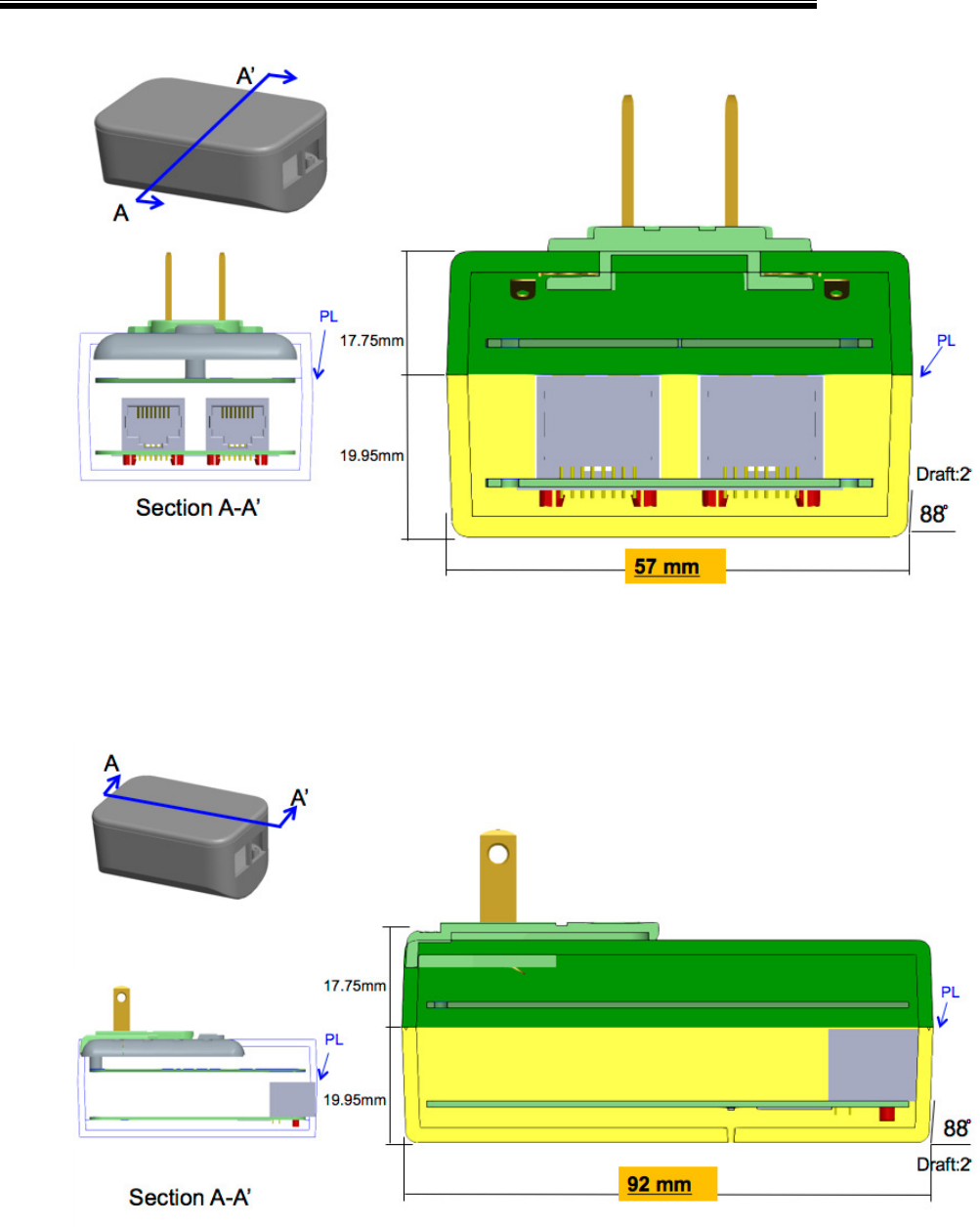
16
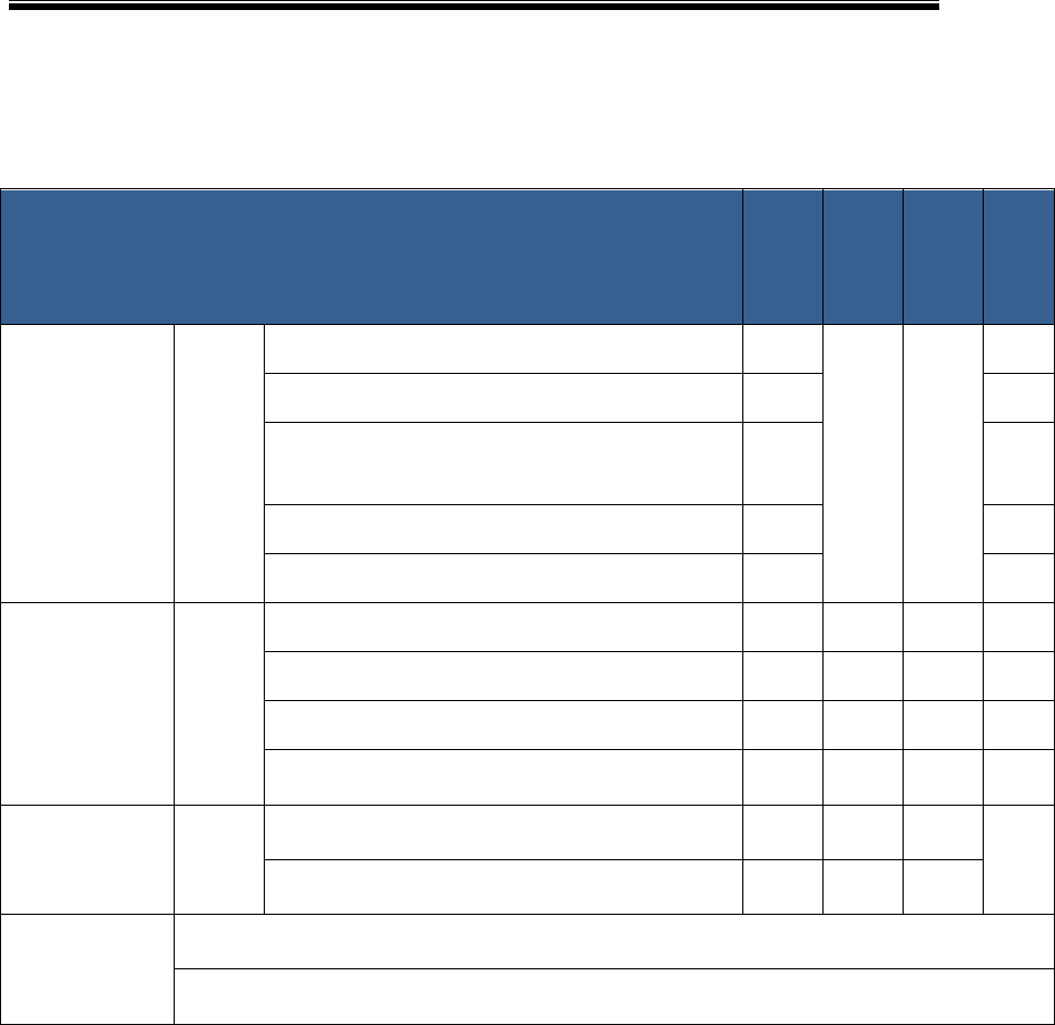
Short Side View: Outline Dimensions (length)
Long Side View: Outline Dimensions (length)
Product Requirement Specification
Mimosa Confidential Page
17
3.9 LED Indicators
The functions of each LED shall be implemented in software. The table below
defines the functions of each LED.
LEDs Description – 3 LEDs
NOTE: No LEDs on the RJ-45 Ethernet connectors
Wi-Fi
Router
Wi-Fi
Extender
Range
Extender
Pass-
through
WAN
(green/red)
Link on RJ45
WAN
C5 CPE status
Green
Yellow
Red
Green On: Good Link on 1000Mbps Y
WAN
LED
OFF
WAN
LED
OFF
Y
Yellow On: Good Link on 100Mbps Y Y
Red On: Good Link on 10Mbps
(this is red because a 10Mbps link is not
desired)
Y Y
Red Blinking: C5 CPE Dead or no connectivity Y Y
Off: Power Off Y Y
LAN
(green/red)
Link on R45
LAN
Green
Yellow
Green On: Good Link on 1000Mbps Y Y Y Y
Yellow On: Good Link on 10/100Mbps Y Y Y Y
Off: No Link Y Y Y Y
Note: No Red status for 10Mbps as this is
acceptable and could be confused as error.
Wi-Fi
(blue)
Link on 11n
2.4G Wi-Fi
Blue
Blue On: Wi-Fi has at lease one client
connected. YYYWi-Fi
LED
OFF
Off: Wi-Fi is disabled or no client is
connected. YYY
System Status
During Boot
System Initialization or reset (software self-test and loading):
Cycle –blink green and red on WAN; blink green and yellow on LAN Wi-Fi Off
System Boot Failure:
Blink Red on WAN and blink yellow on LAN, Wi-Fi Off
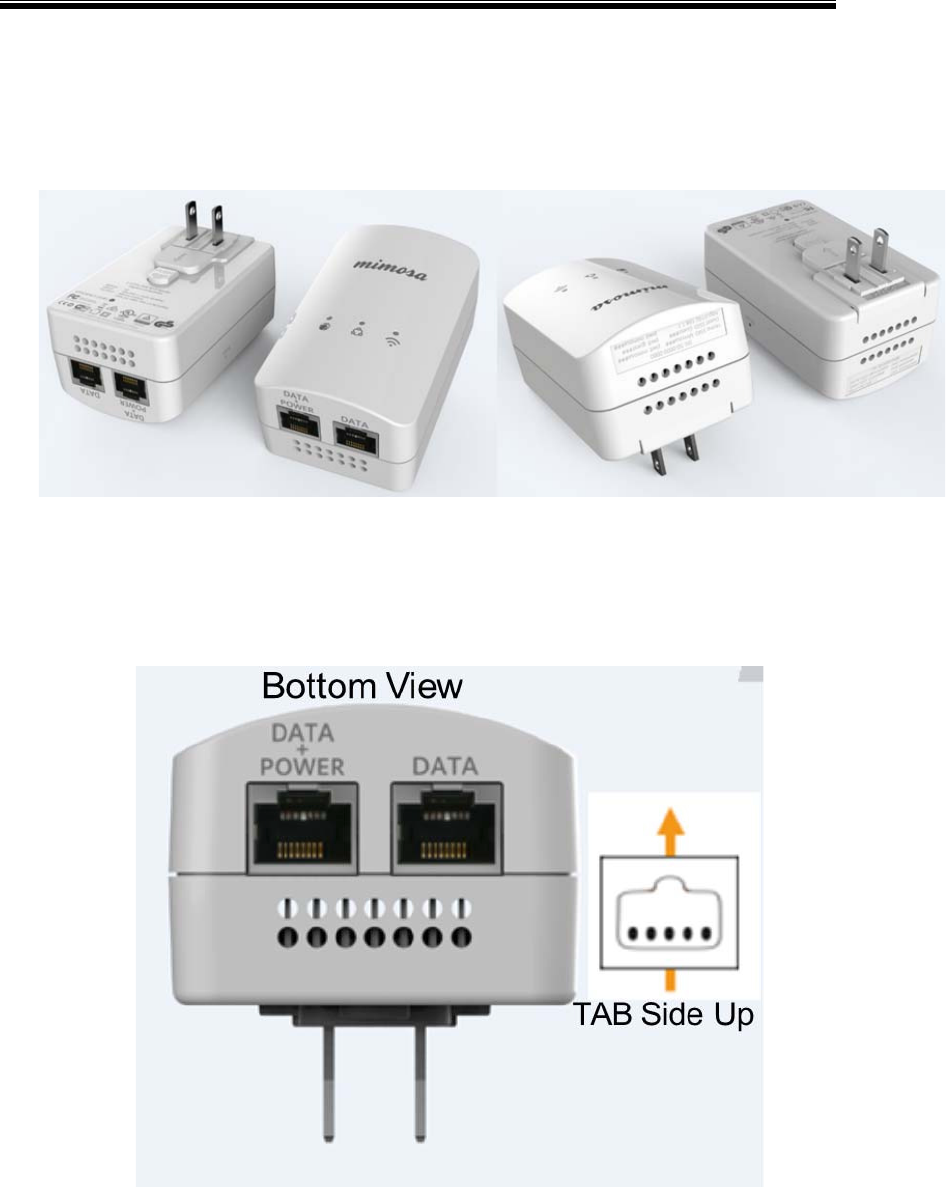
3.9.1 LED Locations
ʔ
See Detailed LED placement from CAD Mechanical Drawings
ʔ
NOTE: There are no LED’s on the Ethernet RJ-45 connectors.

Product Requirement Specification
Mimosa Confidential Page
18
3.10 Reset Button
The reset button can be accessed through a pinhole with a paperclip or sharp
object.
Press and release the reset button to reboot the router.
Press and hold the reset button for five seconds or more to reset the router
to factory default settings

Product Requirement Specification
Mimosa Confidential Page
19
4 SW Features
Version 1.6 – May 22, 2015
David Stiff, Mimosa Networks
ʔ
Interface Use Case Diagram (diagram 1)
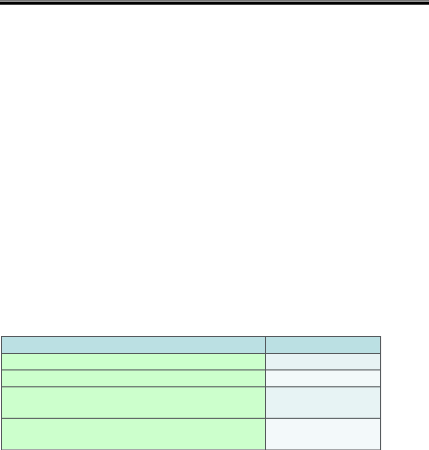
This table describes the basic connection description and requirements for the ports on the
PoE Wi-Fi Router.
Mimosa Plug-In POE Wi-Fi Gateway Software specification
Interface Uses
(diagram 1)
WAN
xPoE Ethernet to WAN
xPoE powers Mimosa C5 Wireless CPE
device
xIP Address/DNS learned from WAN
(DHCP or Static)
LAN
xEthernet to Home Network
xBridged connection to SSIDs
xNAT routed to WAN
xNot Bridged to Guest SSID
xRouter Manages DHCP Server for IP
Assignments
Wi-Fi SSIDs
xHome Network SSIDs: bridged to LAN
except Guest SSID, NAT routed to WAN
xGuest SSID, traffic only allowed to
Internet via WAN, NAT routed to WAN
xRouter Manages DHCP Server for IP
Assignments
Mimosa PoE Wi-Fi Router Operational Modes
ʔ

Product Requirement Specification
Mimosa Confidential Page
20

Product Requirement Specification
Mimosa Confidential Page
21
This table describes the four operational modes for the PoE Wi-Fi Router and what functions
are enabled for each mode. How will C5/C5c/C5i be configured?
Mimosa Plug-In POE Wi-Fi Gateway Software specification
Configuration
Modes
Only enable
auto config
mode when
device powered
on with Factory
Defaults
Config can be
changed
manually once
auto config is
done.
PoE Wi-Fi Router
ʔ
Default Mode
Detection: WAN cable plugged in
xWAN Router (NAT/DHCP) between WAN
and LAN/Wireless
xBridge traffic between LAN and Wi-Fi
xWi-Fi always in Access Point mode for
Wi-Fi certified 802.11bgn clients
xDefaults:
SSID = MimosaXYZ (last 3 digits of
serial number)
WPA-PSK passphrase = mimosaXYZ
(last 3 digits of serial number)
Web GUI password = mimosaXYZ
PoE Pass-through
ʔ
Configure Option from GUI
xWAN Router (NAT/DHCP) OFF
xWi-Fi OFF
xBridge all packets from LAN Ù WAN
Wi-Fi Extension
ʔ
See Diagram 2
for details
Detection: Only LAN port connected to
WAN router
xWAN Router (NAT/DHCP) OFF
xLearn SSID configuration from WAN
Router
xEnable SSIDs
xPick different Wi-Fi Channel from WAN
Router
xBridge traffic from SSIDs to LAN port
(DHCP/Gateway provided by WAN
Router). Keep Guest traffic separate
from Home Network.
xNo Router/DHCP function
xWireless always in Access Point mode
for Wi-Fi certified 802.11bgn clients
Range Extender Detection: no LAN connection to main

Product Requirement Specification
Mimosa Confidential Page
22
ʔRouter and auto-configured as Wi-Fi
Extension. I.e.: Plug is once to configure
as Wi-Fi Extension and then power on
again w/out connecting to main router.
Configured manually via GUI
xEnable Wi-Fi as repeater
xWAN Router (NAT/DHCP) OFF
xBridge traffic to LAN if connected
x
Bridge traffic to the main Wi-Fi router
ʔ
Wireless Extension and Repeater Use Case (diagram 2)
This table describes the minimum viable feature set for the PoE Wi-Fi Router.
Wireless Wireless mode 802.11bgn
Bandwidth
x20MHz
x40 MHz (deny 20 MHz clients)
x
20/40MHz dynamic
Aggregation in 11n mode
xA-MPDU
SSID
xSupport 4 virtual AP
PowerSave
xSupport WMM-Power Save
QoS
xEDCA WMM (WMM QoS)
xQoS-DSCP configurable via web UI
Other parameter
configurable via Web UI
xTransmit power adjustable (four level:
full, 1/2, 1/4, 1/8)
xDTIM
xGuard interval (short/long)
x
Beacon Interval
Channel Setting
xAuto via boot time scan – pick channel
with least other SSIDs detected.
x
Manual Select from channel pick list.

Product Requirement Specification
Mimosa Confidential Page
23
Closed Network
xOption to hide SSID, configurable per
SSID
Guest SSID
ʔ
xOption to make an SSID a Guest SSID
xCreate Guest SSID as WPA/WPA2 with
default (no captive portal)
xDefault SSID = GuestXYZ
(last 3 digits of serial number)
WPA passphrase = guestXYZ (last 3
digits of serial number)
xAllow option to enable client isolation to
only allow Guest Wi-Fi traffic to go to
internet (WAN)
Range Extender (repeater)
Site Survey
xSite Survey Mode to discover SSIDs and
display. User will select SSID and enter
security credentials to repeat. Display
SSID, Signal Strength, Security mode
(None, WPA-PSK, WPA2-PSK, WEP).
xAllow selection of SSID, Entry of
Encryption Key to enable repeating.
Security Authentication
xWPA/WPA2 Personal (PSK)
xWPA/WPA2 Enterprise 802.1X
Authentication with RADIUS Client
x
Enterprise (802.1x): PEAP, TTLS, TLS
Encryption
xAES, TKIP, WEP 64/128
Certification Wi-Fi Alliance Wi-Fi Certified only for mandatory items
Router Function
for Ethernet as
WAN
NAT router
xSupport to enable/disable
SPI Firewall
xStateful Firewall to allow traffic session
back through NAT router
NAT Port Forwarding
(WAN to LAN)
xAction: Allow, Block
xSource IP (Any, Single IP, Range of IP)
xDestination IP (Single IP)
xInternal Port (Single Port, range 1-
65535)

Product Requirement Specification
Mimosa Confidential Page
24
Rate Limiting on WAN
xSpecify Upstream/Downstream WAN
rate limits in Kbps
Static routes Route Name, Destination IP, IP Subnet
Mask, Gateway IP Address
DHCP Server for LAN and
Wireless clients
xDomain Name, Start IP, End IP, Lease
Time (hours: default 24 Hr, range
options 1-900 Hr)
xMAC Address based static assignment
(Name, IP address, MAC Address)
xCheck if IP in use before assigning to
prevent duplicate IP addresses
x
DHCP Lease Display Table
PPPoE client
For Authentication
xPPP username/password
xAuthentication options:
Auto/PAP/CHAP/MS-CHAP/MS-CHAPv2
PPTP Client
For VPN
xPPTP Server Address
xPPP username/password
xAuthentication options:
Auto/PAP/CHAP/MS-CHAP/MS-CHAPv2
xEncryption: None, MPPE 128bit, 40 bit
x
MTU Setting: Default 1460
Management
and
Administration
Management ACL
xPermit WebUI/SNMP from Single IP, IP
Range, Subnet mask
Management Password
xDefault = mimosa
xAllow changing
Time Setting
xSet Time and Time Zone
xSet NTP server.
Web UI
xMimosa GUI similar to B5/A5
xHTTP/HTPTS
xEnable/Disable System Management
from LAN. This will prevent LAN side
user from changing router mode
options and disconnecting Gateway
from WAN.
xKeep Monitoring/Status and Guest
config options avail from LAN
Network setting
xIPv4 static IP (IP, Netmask, Gateway,
DNS1, DNS2)
xDHCP client on WAN (Ethernet)
(Requested hostname, IP, Netmask,
Gateway, DNS1, DNS2)

Product Requirement Specification
Mimosa Confidential Page
25
xDHCP Failover IP assignment if no
DHCP response (IP, Netmask, Gateway,
DNS1, DNS2)
Statistics
xStatistics of wired, wireless associated
stations accessible
SNMP
xMIBII (survey throughput, data
statistics, location)
x
SNMP Community String RO setting
Wireless ACL
xBased on MAC address (White List &
Black List individual MAC Addresses)
Firmware upgrade
xvia Web UI
System log
xInternal (WebUI) and External (Syslog)
xSet External Syslog server IP
Diagnostics
xPing, Traceroute
Config
xReset to Factory Defaults
xBackup & Restore from Web UI to local
laptop file system
x
Reboot
Mimosa Cloud
Management
A binary will be provided to allow config
and monitoring of the device from Mimosa
Cloud for the following items:
xDevice monitoring (IP, Mac, Name,
Client count for wireless)
xRF Country Code Unlock
x
Configuration Push
Connectivity
Monitoring
CPE Available WAN Ethernet port up.
Success = port up
Fail = port down
Service Provider Gateway Ping WAN default gateway. This is the
default gateway from the WAN side of the
router. Learned from WAN side DHCP or
manual WAN IP setting.
Success = good ping response

Product Requirement Specification
Mimosa Confidential Page
26
Fail = no ping response
Internet Access (TCP) TCP connectivity (tcping) to well known
global web sites:
mimosa.co
google.com
youtube.com
facebook.com
independent.co.uk
buzzfeed.com
upsocl.com
scribd.com
ask.fm
diply.com
baidu.com
Success = successful tcp connection to
any of above sites.
Fail = failed tcp connection to all sites
Internet Access (DNS) DNS Server availability. Successful DNS
lookup for above names. This is the DNS
server from the WAN side of the router.
Learned from WAN side DHCP or manual
DNS setting.
Success = successful lookup of any of the
above DNS servers
Fail = failed DNS lookup for all sites
Connectivity test monitoring should be configurable to on/off with on
as default. Tests should run every 60 seconds.
See Diagram 3 for examples for example of how monitoring will be
represented to users in the GUI.
ʔ
Connectivity Testing (Diagram 3)

Product Requirement Specification
Mimosa Confidential Page
27

Product Requirement Specification
Mimosa Confidential Page
28
5 Environmental
xOperating:
oTemp: 0° C to +40° C (32° F to +104° F)
oHumidity: 5% to 95% non-condensing
xStorage and Transportation Temperature Range:
oTemp: -25° C to +65° C (-13° F to +149° F)

Product Requirement Specification
Mimosa Confidential Page
29
6 Reliability
xMTBF: >50,000 hours

Product Requirement Specification
Mimosa Confidential Page
30
7 Regulatory and Certifications
xEN55022/24 Class B
xEN 300 328
xEN 301 489 Part 1
xEN 301 489 Part 17
xUL/cUL/IEC/EN 60950
xIC RSS247
xCE Marked
xSAA/RCM with RCM logo marked
xFCC Part 15B+15C
xTUV (EN60950-1 + EN61984)
xRoHS Compliance
xWi-Fi Alliance Wi-Fi CERTIFIED™
Product Requirement Specification
Mimosa Confidential Page
31
FCC WARING STATEMENT
This equipment has been tested and found to comply with the limits for a Class B digital
device, pursuant to part 15 of the FCC Rules. These limits are designed to provide
reasonable protection against harmful interference in a residential installation. This equipment
generates, uses and can radiate radio frequency energy and, if not installed and used in
accordance with the instructions, may cause harmful interference to radio communications.
However, there is no guarantee that interference will not occur in a particular installation. If
this equipment does cause harmful interference to radio or television reception, which can be
determined by turning the equipment off and on, the user is encouraged to try to correct the
interference by one or more of the following measures:
—Reorient or relocate the receiving antenna.
—Increase the separation between the equipment and receiver.
—Connect the equipment into an outlet on a circuit different from that to which the receiver is
connected.
—Consult the dealer or an experienced radio/TV technician for help.
zAny changes or modifications not expressly approved by the party responsible for
compliance could void the authority to operate
equipment.
zThis device and its antenna must not be co-
located or operating in conjunction with any other antenna or transmitter.
zFor product available in the USA/Canada market, only channel 1~11 can be operated.
Selection of other channels is not possible
FCC RF Radiation Exposure Statement:
This equipment complies with FCC radiation exposure limits set forth for an uncontrolled
environment. This equipment should be installed and operated with minimum distance 20cm
between the radiator & your body.

Product Requirement Specification
Mimosa Confidential Page
32
IC WARING STATEMENT
Industry Canada ICES-003 Compliance Label:
CAN ICES-3 (*)/NMB-3(*)
* Insert either “A” or “B” but not both to identify the applicable Class of ITE.
Co-located
This device and its antenna(s) must not be co-located or operating in conjunction with any
other antenna or transmitter.
Cet appareil et son antenne (s) ne doivent pas être situés ou fonctionner en conjonction avec
une autre antenne ou émetteur.
RSS247 2.3 External RF Power Amplifiers (ERFPA)
Under Industry Canada regulations, this external radio frequency power amplifier (insert
Industry Canada certification number of radio frequency power amplifier) may only be used
with the transmitter with which the amplifier has been certified by Industry Canada. The
certification number for the transmitter with which this amplifier is permitted to operate is IC:
11823A-10000033.
En vertu des règlements d'Industrie Canada, cet amplificateur de puissance de fréquence
radio externe (insérer Industrie Canada numéro de certification de l'amplificateur de
puissance de fréquence radio) ne peut être utilisé avec l'émetteur avec lequel l'amplificateur a
été certifié par Industrie Canada. Le numéro de certification pour l'émetteur avec lequel cet
amplificateur est autorisée à opérer est IC:11823A-10000033.
RSS-Gen Issue 4 8.4
This device complies with Industry Canada’s licence-exempt RSSs. Operation is subject to
the following two conditions: (1) This device may not cause interference; and (2) This device
must accept any interference, including interference that may cause undesired operation of
the device.
Le présent appareil est conforme aux CNR d'Industrie Canada applicables aux appareils
radio exempts de licence. L'exploitation est autorisée aux deux conditions suivantes : (1)
l'appareil ne doit pas produire de brouillage, et (2) l'utilisateur de l'appareil doit accepter tout
brouillage radioélectrique subi, même si le brouillage est susceptible d'en compromettre le
fonctionnement.

Product Requirement Specification
Mimosa Confidential Page
33
IC Radiation Exposure Statement:
mobile device
This equipment complies with IC RSS-102 radiation exposure limits set forth for an
uncontrolled environment. This equipment should be installed and operated with minimum
distance 20cm between the radiator & your body.
Cet équipement est conforme aux limites d'exposition de rayonnement de la IC RSS-102 rf
déterminées pour un environnement non contrôlé. Cet équipement devrait être installé et
actionné avec une distance minimum de 20 centimètres entre le radiateur et votre corps.