Mimosa Networks 100-00036 11 GHz Backhaul Radio User Manual Draft
Mimosa Networks, Inc. 11 GHz Backhaul Radio Draft
User Manual -Draft

B11User Guide
Warnings, Warranty, Compliance &
Regulatory Statements
Export Control
These commodities, technology, or software were exported from the United States in accordance with the Export
Administration Regulations. Diversion contrary to U.S. law is prohibited.
Important Safety and Handling Information
Failure to follow any of the safety instructions in this guide, instructions on any Mimosa provided packaging, and
heed WARNINGS (indicated by ), could result in fire, electric shock or other injury, and incur damage to this product
or other property and voiding of the product Limited Warranty.
There are no End User serviceable parts inside the equipment.
Read all operating and safety instructions contained herein and accompanying the product as provided by Mimosa
Networks, Inc. (“Mimosa”)
Occupational/controlled exposure limits apply when using the equipment. Persons exposed as a consequence of
their employment should use appropriate means to mitigate their RF exposure.
Electrical Safety Information
Do not operate this product in any location that can be submerged by water.
Do not install or maintain this product during the presence of an electrical storm to avoid risk of electric shock from
lightning.
Power specifications are indicated on the power supply provided with the Mimosa product. Connecting to any
power source that does not meet the voltage, frequency and current requirements listed may damage the power
supply or product, and pose a fire hazard.
Depending on the product model, your product will be classified either as a safety class I or safety class II compliant
device. Class I devices require a connection to earth ground (3-terminal plug), while class II devices incorporate a 2-
terminal plug
Class I: This device is intended for use with a grounded safety outlet. A safety ground wire (3-wire outlet plug type) is
included on the provided AC adapter. Under no circumstances should you replace the provided detachable power
cord with a non-grounded (2-wire outlet plug type) or use any adapter plugs which do not provide ground wire
continuity.
Class II: Safety Class II-compliant devices include supplemental insulation to protect against electric shock, and do
not require a connection to earth ground.
Installation of the product must comply with local and national electrical codes.
Mandatory Grounding Instructions
IMPORTANT: In order to comply with the Mimosa Limited Warranty conditions in this document, you must properly
ground the device according to these instructions. Failure to properly ground the device will violate the product
warranty.
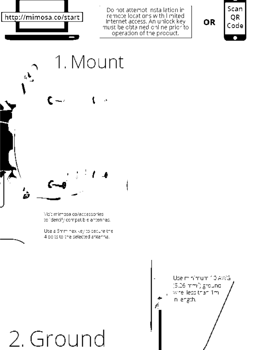
A minimum grounding wire of 10 AWG (5.26 mm2) with a secured grounding terminal, and shorter in length than 1
meter is required. It is NOT supplied with the product.
1. Ensure that NO power is being supplied to the product. 2. Locate the Ground point screw next to the Ground icon
on the device 3. Remove the provided Ground Screw 4. Thread the ground wire terminal and ground wire meeting
the above specifications over the screw removed in the previous step. 5. Replace and tighten the screw with the
threaded ground terminal and cable at the product Ground point. 6. Secure the other end of the grounding cable to
the properly grounded structure (pole, tower, mast, etc.) meeting local and national electrical regulations and codes.
End User Product Warranty
Products purchased from Mimosa Networks, Inc. (“Mimosa”) are warranted against defects in material, and
workmanship for a period of either (i) twelve (12) months from the date of activation, or (ii) thirty-six (36) months
from the original date of shipment, whichever is earlier. Please go to www.mimosa.co/warranty to determine
whether your product is in warranty.
The sole responsibility of Mimosa under this warranty shall be limited to the repair or replacement of in-warranty
defective product, at Mimosa’s sole option.
Out of warranty products shipped to Mimosa will not be returned. This warranty does not cover costs associated
with the removal and/or reinstallation of the product for repair nor for any parts that are readily replaced in normal
use.
Mimosa or its designated partner will repair or replace product found to be defective during the defined warranty
period.
The End User is responsible for delivering defective product in accordance with Mimosa’s published Return Material
Authorization (RMA) processes.
Limitation of Warranty
Mimosa’s product warranty is invalidated if the RMA product is altered or otherwise tampered with in a manner that
modifies the product from its original shipping configuration and/or form factor, and could violate the End User’s
authority to operate the equipment, unless said activity was performed by or with the written authorization of a
Mimosa representative.
Modifications include: (a) External surfaces that have been painted, labeled, or otherwise modified from the original
shipping condition. (b) Modifications of the product with third party hardware, firmware, and/or software. (c) Any
product subjected to abnormal physical or electric stress, including, but not limited to, lightning strikes, negligence,
accident, or misuse. (d) Any product damaged due to incorrect installation, including, but not limited to, improper
product mounting, cabling, cabling defects or connection to power. (e) Failure induced by connected third party
products.
Improper grounding, or failure to ground the product as instructed in this guide will void the End User warranty.
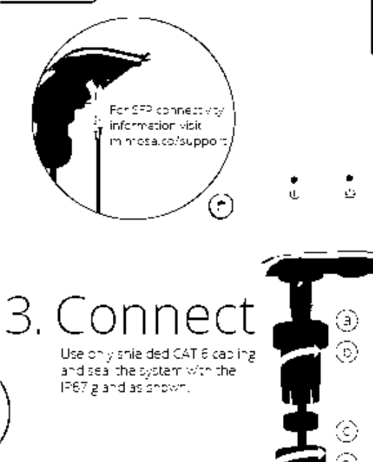
Mimosa will not warrant any product which has been installed outdoors without the use of minimum CAT 6
shielded Ethernet cable and/or proper earth grounding.
Disclaimer
EXCEPT FOR ANY EXPRESS WARRANTIES PROVIDED HEREIN, MIMOSA NETWORKS AND ITS SUBSIDIARIES, LICENSORS
AND AFFILIATES ( COLLECTIVELY, “MIMOSA”), AND ANY THIRD PARTY DATA, SERVICE, SOFTWARE AND HARDWARE
PROVIDERS MAKE NO OTH- ER REPRESENTATION OR WARRANTY OF ANY KIND AND HEREBY DISCLAIM ALL WAR-
RANTIES, EXPRESS OR IMPLIED, STATUTORY OR OTHERWISE, INCLUDING, BUT NOT LIMITED TO, ANY
REPRESENTATIONS OR WARRANTIES OF DESIGN, MERCHANTABILITY, ACCURACY, QUALITY OF SERVICE OR RESULTS,
AVAILABILITY, LACK OF VIRUSES, QUIET ENJOYMENT, FITNESS FOR A PARTICULAR PURPOSE, NON-INFRINGEMENT
AND ANY WARRANTIES ARISING FROM ANY COURSE OF DEALING, USAGE OR TRADE PRACTICE IN CONNECTION
WITH SUCH PRODUCTS AND SERVICES. YOU ACKNOWLEDGE THAT NEITHER MIMOSA NOR ITS THIRD PARTY
PROVIDERS CONTROL YOUR EQUIPMENT
OR THE TRANSFER OF DATA OVER COMMUNICATIONS FACILITIES, INCLUDING THE INTERNET, AND THAT THE
PRODUCTS AND SERVICES PROVIDED BY MIMOSA MAY BE SUBJECT TO LIMITATIONS, INTERRUPTIONS, DELAYS,
CANCELLATIONS AND OTHER PROBLEMS INHERENT IN THE USE OF COMMUNICATIONS FACILITIES. MIMOSA AND
ANY THIRD PARTY PROVIDERS ARE NOT RESPONSIBLE FOR ANY INTERRUPTIONS, DELAYS, CANCELLATIONS,
DELIVERY FAILURES, DATA LOSS, CONTENT CORRUPTION, PACKET LOSS, OR OTHER DAMAGE RESULTING FROM ANY
OF THE FOREGOING.
IN ADDITION, MIMOSA MAKES NO WARRANTY OR UNDERTAKING, AND MAKES NO REPRESENTATION OF ANY KIND
THAT THE LICENSED PRODUCTS WILL MEET YOUR REQUIREMENTS, ACHIEVE ANY INTENDED RESULTS, BE
COMPATIBLE OR WORK WITH ANY OTHER SOFTWARE, APPLICATIONS, SYSTEMS OR SERVICES, OPERATE WITHOUT
INTERRUPTION, MEET ANY PERFORMANCE OR RELIABILITY STANDARDS, BE ERROR FREE OR THAT ANY ERRORS OR
DEFECTS CAN OR WILL BE CORRECTED, OR THAT THE LICENSED PRODUCTS ARE NOT VULNERABLE TO FRAUD OR
UNAUTHORIZED USE.
Limitation of Liability
EXCEPT TO THE EXTENT PROHIBITED BY THE LAWS IN YOUR JURISDICTION, IN NO EVENT WILL MIMOSA OR ITS
SUPPLIERS OR LICENSORS BE LIABLE FOR SPECIAL, INCIDENTAL, CONSEQUENTIAL OR OTHER DAMAGES
(INCLUDING LOST PROFIT, LOST DATA, OR DOWNTIME COSTS), NOR FOR DAMAGES BASED ON UNAUTHORIZED USE
OR ACCESS, ARISING OUT OF THE USE, INABILITY TO USE, OR THE RESULTS OF USE OF THE PRODUCT, WHETHER
BASED IN WARRANTY, CONTRACT, TORT OR OTHER LEGAL THEORY, AND WHETHER OR NOT ADVISED OF THE
POSSIBILITY OF SUCH DAMAGES. IN NO EVENT SHALL MIMOSA, ITS SUPPLIERS’ OR ITS LICENSORS’ DIRECT LIABILITY
EXCEED THE VALUE OF THE LICENSED PRODUCTS GIVING RISE TO SUCH LIABILITY. THESE LIMITATIONS SHALL
APPLY NOTHWITHSTANDING ANY FAILURE OF ESSENTIAL PURPOSE OF ANY LIMITED REMEDY. IN NO EVENT SHALL
MIMOSA BE RESPONSIBLE FOR DAMAGES OR CLAIMS OF ANY NATURE OR DESCRIPTION RELATING TO NETWORK
PERFORMANCE, INCLUDING COVERAGE, YOUR SELECTION OF MIMOSA PRODUCTS FOR YOUR PARTICULAR
APPLICATION AND/OR FAILURE OF MIMOSA PRODUCTS TO MEET GOVERNMENT OR REGULATORY REQUIREMENTS.
Some legal jurisdictions do not allow exclusions of implied warranties or conditions, or for the exclusion or
limitation of liability for incidental or consequential damages, so the above exclusion may not apply to you. You may
have other rights specific to your legal jurisdiction. EXCEPT TO THE EXTENT ALLOWED BY THE LAW OF YOUR
JURISDIC- TION, THESE WARRANTY TERMS DO NOT EXCLUDE, RESTRICT OR MODIFY, AND ARE IN ADDITION TO, ANY
MANDATORY STATUTORY RIGHTS APPLICABLE TO YOU IN THE LICENSE OF ANY EMBEDDED SOFTWARE. The United
Nations Convention on Contracts for the International Sale of Goods shall not apply to any transactions regarding
the sale of the Products.
FCC
This device complies with part 15 of the FCC Rules. Operation is subject to the following two conditions:
(1) This device may not cause harmful interference, and (2) this device must accept any interference received,
including interference that may cause undesired operation.
NOTE: This equipment has been tested and found to comply with the limits for a Class A digital device, pursuant to
part 15 of the FCC Rules. These limits are designed to provide reasonable protection against harmful interference
when the equipment is operated in a commercial environment. This equipment generates, uses, and can radiate
radio frequency energy and, if not installed and used in accordance with the instruction manual, may cause harmful
interference to radio communications. Operation of this equipment in a residential area is likely to cause harmful
interference in which case the user will be required to correct the interference at his own expense.
The radiated output power of this device is below the FCC radio frequency exposure limits. Nevertheless, the device
should be used in such a manner that the potential for human contact during the normal operation is minimized. In
order to avoid the possibility of exceeding the FCC radio frequency exposure limit, human proximity to the antenna
should be more than 9.53m.
Any changes or modifications not expressly approved by Mimosa could void the user’s authority to operate this
device.
Australia & New Zealand
Warning: This is a Class A product. In a domestic environment this product may cause radio interference in which
case the user may be required to take adequate measures.
European Compliance Statement
CE Marking on this this product represents that this product complies with all requirements that are applicable to it.
Alert sign must be indicated if a restriction on use applied to the product and it must follow the CE marking.
Europe EU Declaration of Conformity
This device can be used in the European Community. A copy of the EU Declaration of Conformity is available at:
www.mimosa.co/compliance.
Български (Bulgarian) - Mimosa Networks, Inc. декларира, че това Mimosa Networks, Inc. приспособление е в
съответствие със съществените изисквания и другите приложими правила на Директива 1999/5/ЕС.
Česky (Czech) - Společnost Mimosa Networks, Inc. tímto prohlašuje, že tento Mimosa Networks, Inc. zařízení je ve
shodě se základními požadavky a dalšími příslušnými ustanoveními směrnice 1999/5/ES.
Dansk (Danish) - Undertegnede Mimosa Networks, Inc. erklærer herved, at følgende udstyr Mimosa Networks, Inc.
enhed overholder de væsentlige krav og øvrige relevante krav i direktiv 1999/5/EF.
Deutsch (German) - Hiermit erklärt Mimosa Networks, Inc., dass sich das Mimosa Net- works, Inc. Gerät in
Übereinstimmung mit den grundlegenden Anforderungen und den übrigen einschlägigen Bestimmungen der
Richtlinie 1999/5/EG befinden.
Eesti (Estonian) - Käesolevaga kinnitab Mimosa Networks, Inc., et see Mimosa Net- works, Inc. seade vastab direktiivi
1999/5/EÜ põhinõuetele ja nimetatud direktiivist tulenevatele teistele asjakohastele sätetele.
English - Hereby, Mimosa Networks, Inc. declares that this Mimosa Networks, Inc. device is in compliance with the
essential requirements and other relevant provisions of Directive 1999/5/EC.
Español (Spanish) - Por medio de la presente Mimosa Networks, Inc. declara que este Mimosa Networks, Inc.
dispositivo cumple con los requisitos esenciales y cualesquiera otras disposiciones aplicables o exigibles de la
Directiva 1999/5/CE.
Ελληνικά (Greek) - Mε την παρούσα, η Mimosa Networks, Inc. δηλώνει ότι αυτή η συσκευή Mimosa Networks, Inc.
συσκευή συμμορφώνεται προς τις βασικές απαιτήσεις και τις λοιπές σχετικές διατάξεις της Οδηγίας 1999/5/ΕΚ.
Français (French) - Par la présente Mimosa Networks, Inc. déclare que ce Mimosa Net- works, Inc. appareil est
conforme aux exigences essentielles et aux autres dispositions pertinentes de la directive 1999/5/CE.
Islenska (Icelandic) - Mimosa Networks, Inc. lýsir því hér með yfir að þetta Mimosa Networks, Inc. tæki fullnægir
lágmarkskröfum og öðrum viðeigandi ákvæðum Evróputil- skipunar 1999/5/EC.
Italiano (Italian) - Con la presente Mimosa Networks, Inc. dichiara che questo Mimosa Networks, Inc. dispositivo è
conforme ai requisiti essenziali ed alle altre disposizioni pertinenti stabilite dalla direttiva 1999/5/CE.
Latviski (Latvian) - Ar šo Mimosa Networks, Inc. deklarē, ka šī Mimosa Networks, Inc. ierīce atbilst Direktīvas
1999/5/EK būtiskajām prasībām un citiem ar to saistītajiem noteikumiem.
Lietuvių (Lithuanian) - Šiuo „Mimosa Networks, Inc.“ deklaruoja, kad šis Mimosa Net- works, Inc. atitinka esminius
reikalavimus ir kitas 1999/5/EB Direktyvos nuostatas.
Magyar (Hungarian) - Alulírott, Mimosa Networks, Inc. nyilatkozom, hogy a Mimosa Networks, Inc. eszköz megfelel a
vonatkozó alapvetõ követelményeknek és az 1999/5/ EC irányelv egyéb elõírásainak.
Malti (Maltese) - Hawnhekk, Mimosa Networks, Inc., jiddikjara li dan Mimosa Networks, Inc. tagħmir jikkonforma
mal-ħtiġijiet essenzjali u ma provvedimenti oħrajn relevanti li hemm fid-Dirrettiva 1999/5/EC.
Nederlands (Dutch) - Hierbij verklaart Mimosa Networks, Inc. dat dit Mimosa Networks, Inc. toestel in
overeenstemming is met de essentiële eisen en de andere bepalingen van richtlijn 1999/5/EG.
Norsk (Norwegian) - Mimosa Networks, Inc. erklærer herved at dette Mimosa Networks, Inc. apparatet er i samsvar
med de grunnleggende kravene og øvrige relevante krav i EU-direktivet 1999/5/EF.
Polski (Polish)- Niniejszym Mimosa Networks, Inc. oświadcza, że ten Mimosa Networks, Inc. urządzenie są zgodne z
zasadniczymi wymogami oraz pozostałymi stosownymi postanowieniami Dyrektywy 1999/5/EC.
Português (Portugese) - Mimosa Networks, Inc. declara que este Mimosa Networks, Inc. dispositivo está em
conformidade com os requisitos essenciais e outras disposições da Directiva 1999/5/CE.
Română (Romanian) - Prin prezenta, Mimosa Networks, Inc. declară că acest Mimosa Networks, Inc. aparat este în
conformitate cu cerinţele esenţiale şi cu celelalte preve- deri relevante ale Directivei 1999/5/CE.
Slovensky (Slovak) - Mimosa Networks, Inc. týmto vyhlasuje, že toto Mimosa Networks, Inc. zariadenie spĺňa
základné požiadavky a všetky príslušné ustanovenia Smernice 1999/5/ES.
Slovensko (Slovene) - Mimosa Networks, Inc. izjavlja, da je ta Mimosa Networks, Inc. naprava skladne z bistvenimi
zahtevami in ostalimi ustreznimi določili direktive 1999/5/ ES.
Suomi (Finnish) - Mimosa Networks, Inc. vakuuttaa täten, että tämä Mimosa Networks, Inc. tyyppinen laite on
direktiivin 1999/5/EY oleellisten vaatimusten ja sitä koskevien direktiivin muiden ehtojen mukainen.
Svenska (Swedish) - Härmed intygar Mimosa Networks, Inc. att denna Mimosa Net- works, Inc. apparat står i
överensstämmelse med de väsentliga egenskapskrav och övriga relevanta bestämmelser som framgår av direktiv
1999/5/EG.
RoHS & WEEE Compliance
User Information for Consumer Products Covered by EU Directive 2002/96/EC on Waste Electric and Electronic
Equipment (WEEE).
This document contains important information for users with regards to the proper disposal and recycling of
Mimosa Networks, Inc. products. Consum- ers are required to comply with this notice for all electronic products
bearing the following symbol:
English - Environmental Information for Customers in the European Union European Directive 2002/96/EC requires
that the equipment bearing this symbol on the product and/or its packaging must not be disposed of with unsorted
municipal waste. The symbol indicates that this product should be disposed of separately from regular household
waste streams. It is your responsibility to dispose of this and other electric and electronic equipment via designated
collection facilities appointed by the government or local authorities. Correct disposal and recycling will help
prevent potential negative consequences to the environment and human health. For more de- tailed information
about the disposal of your old equipment, please contact your local authorities, waste disposal service, or the shop
where you purchased the product.
Български (Bulgarian) - Информация относноопазването на околната среда за потребители вЕвропейския
съюз
Европейска директива 2002/96/EC изисква уредите, носещи този символ върху изделието и/или опаковката
му, да не се изхвърля т с несортирани битови отпадъци. Символът обозначава, че изделието трябва да се
изхвърля отделно от сметосъбирането на обикновените битови отпадъци. Ваша е отговорността този и
другите електрически и електронни уреди да се изхвърлят в предварително определени от държавните или
общински органи специализирани пунктове
за събиране. Правилното изхвърляне и рециклиране ще спомогнат да се предотвратят евентуални вредни
за околната среда и здравето на населението последствия. За по-подробна информация относно
изхвърлянето на вашите стари уреди се обърнете към местните власти, службите за сметосъбиране или
магазина, от който сте закупили уреда.
Čeština (Czech) - Informace o ochraně životníhoprostředí pro zákazníky v zemích Evropské unie Evropská směrnice
2002/96/ES zakazuje, aby zařízení označené tímto symbolem na produktu anebo na obalu bylo likvidováno s
netříděným komunálním odpadem. Tento symbol udává, že daný produkt musí být likvidován odděleně od běžného
komunálního odpadu. Odpovídáte za likvidaci tohoto produktu a dalších elektrických a elektronických zařízení
prostřednictvím určených sběrných míst stanovených vládou nebo místními úřady. Správná likvidace a recyklace
pomáhá předcházet potenciálním negativním dopadům na životní prostředí a lidské zdraví. Podrobnější informace
o likvidaci starého vybavení si laskavě vyžádejte od místních úřadů, podniku zabývajícího se likvidací komunálních
odpadů nebo obchodu, kde jste produkt zakoupili.
Dansk (Danish) - Miljøinformation for kunder i EU EU-direktiv 2002/96/EF kræver, at udstyr der bærer dette symbol
på produktet og/eller emballagen ikke må bortskaffes som usorteret kommunalt affald. Symbolet betyder, at dette
produkt skal bortskaffes adskilt fra det almindelige husholdningsaffald. Det er dit ansvar at bortskaffe dette og
andet elektrisk og elektronisk udstyr via bestemte indsamlingssteder udpeget af staten eller de lokale myndigheder.
Korrekt bortskaffelse og genvinding vil hjælpe med til at undgå mulige skader for miljøet og menneskers sundhed.
Kontakt venligst de lokale myndigheder, renovationstjenesten eller den butik, hvor du har købt produktet,
angående mere detaljeret information om bortskaffelse af dit gamle udstyr.
Deutsch (German) - Umweltinformation für Kunden innerhalb der Europäischen Union Die Europäische Richtlinie
2002/96/EC verlangt, dass technische Ausrüstung, die direkt am Gerät und/oder an der Verpackung mit diesem
Symbol versehen ist, nicht zusam- men mit unsortiertem Gemeindeabfall entsorgt werden darf. Das Symbol weist
darauf hin, dass das Produkt von regulärem Haushaltmüll getrennt entsorgt werden sollte. Es liegt in Ihrer
Verantwortung, dieses Gerät und andere elektrische und elektronische Geräte über die dafür zuständigen und von
der Regierung oder örtlichen Behörden dazu bestimmten Sammelstellen zu entsorgen. Ordnungsgemäßes
Entsorgen und Recyceln trägt dazu bei, potentielle negative Folgen für Umwelt und die menschliche Gesundheit zu
vermeiden. Wenn Sie weitere Informationen zur Entsorgung Ihrer Altgeräte benötigen, wenden Sie sich bitte an die
örtlichen Behörden oder städtischen Entsorgungsdienste oder an den Händler, bei dem Sie das Produkt erworben
haben.
Eesti (Estonian) - Keskkonnaalane informatsioon Euroopa Liidus asuvatele klientidele Euroopa Liidu direktiivi
2002/96/EÜ nõuete kohaselt on seadmeid, millel on tootel või pakendil käesolev sümbol keelatud kõrvaldada koos
sorteerimata olmejäätmetega. See sümbol näitab, et toode tuleks kõrvaldada eraldi tavalistest
olmejäätmevoogudest. Olete kohustatud kõrvaldama käesoleva ja ka muud elektri- ja elektroonikaseadmed riigi või
kohalike ametiasutuste poolt ette nähtud kogumispunktide kaudu. Seadmete korrektne kõrvaldamine ja
ringlussevõtt aitab vältida võimalikke negatiivseid tagajärgi keskkonnale ning inimeste tervisele. Vanade seadmete
kõrvaldamise kohta täpsema informatsiooni saamiseks võtke palun ühendust kohalike ametiasutustega, jäätmekäit-
lusfirmaga või kauplusega, kust te toote ostsite.
Español (Spanish) - Información medioambiental paraclientes de la Unión Europea La Directiva 2002/96/CE de la UE
exige que los equipos quel leven este símbolo en el propio aparato y/o en su embalaje no deben eliminarse junto
con otros residuos ur- banos no seleccionados. El símbolo indica que el producto en cuestión debe separarse de los
residuos domésticos convencionales con vistas a su eliminación. Es responsabili- dad suya desechar este y
cualesquiera otros aparatos eléctricos y electrónicos a través de los puntos de recogida que ponen a su disposición
el gobierno y las autoridades locales. Al desechar y reciclar correctamente estos aparatos estará contribuyendo a
evitar posibles consecuencias negativas para el medio ambiente y la salud de las per- sonas. Si desea obtener
información más detallada sobre la eliminación segura de su aparato usado, consulte a las autoridades locales, al
servicio de recogida y eliminación de residuos de su zona o pregunte en la tienda donde adquirió el producto.
Ελληνικά (Greek) - Στοιχεία περιβαλλοντικής προστασίας για πελάτες εντός της ΕυρωπαϊκήςΈνωσης Σύμφωνα με
την Κοινοτική Οδηγία 2002/96/EC, ο εξοπλισμός που φέρει αυτό το σύμβολο στο προϊόν ή/και τη συσκευασία του
δεν πρέπει να απορρίπτεται μαζί με τα μη διαχωρισμένα αστικά απορρίμματα. Το σύμβολο υποδεικνύει ότι αυτό
το προϊόν θα πρέπει να απορρίπτεται ξεχωριστά από τα συνήθη οικιακά απορρίμματα. Είστε υπεύθυνος για την
απόρριψη του παρόντος και άλλου ηλεκτρικού και ηλεκτρονικού εξοπλισμού μέσω των καθορισμένων
εγκαταστάσεων συγκέντρωσης απορριμμάτων, οι οποίες ορίζονται από το κράτος ή τις αρμόδιες τοπικές αρχές. Η
σωστή απόρριψη και ανακύκλωση συμβάλλει στην πρόληψη ενδεχόμενων αρνητικών επιπτώσεων στο περιβάλλον
και την υγεία. Για περισσότερες πληροφορίες σχετικά με την απόρριψη του παλαιού σας εξοπλισμού,
επικοινωνήστε με τις τοπικές αρχές, τις υπηρεσίες αποκομιδής απορριμμάτων ή το κατάστημα από το οποίο
αγοράσατε το προϊόν.
Français (French) - Informations environnementales pour les clients de l’Unioneuropéenne La directive européenne
2002/96/CE exige que l’équipement , sur lequel est apposé ce symbole sur le produit et/ou son emballage ne soit
pas jeté avec les autres ordures ménagères. Ce symbole indique que le produit doit être éliminé dans un circuit
distinct de celui pour les déchets des ménages. Il est de votre responsabilité de jeter ce matériel ainsi que tout autre
matériel électrique ou électronique par les moyens de collecte indiqués par le gouvernement et les pouvoirs publics
des collectivités territori- ales. L’élimination et le recyclage en bonne et due forme ont pour but de lutter contre
l’impact néfaste potentiel de ce type de produits sur l’environnement et la santé pub- lique. Pour plus
d’informations sur le mode d’élimination de votre ancien équipement, veuillez prendre contact avec les pouvoirs
publics locaux, le service de traitement des déchets, ou l’endroit où vous avez acheté le produit.
Italiano (Italian) - Informazioni relative all’ambiente per i clienti residenti nell’Unione Europea La direttiva europea
2002/96/EC richiede che le apparecchiature contrassegnate con questo simbolo sul prodotto e/o sull’imballaggio
non siano smaltite insieme ai rifiuti urbani non differenziati. Il simbolo indica che questo prodotto non deve essere
smaltito insieme ai normali rifiuti domestici. È responsabilità del proprietario smaltire sia questi prodotti sia le altre
apparecchiature elettriche ed elettroniche mediante le specifiche strutture di raccolta indicate dal governo o dagli
enti pubblici locali. Il corret- to smaltimento ed il riciclaggio aiuteranno a prevenire conseguenze potenzialmente
negative per l’ambiente e per la salute dell’essere umano. Per ricevere informazioni più dettagliate circa lo
smaltimento delle vecchie apparecchiature in Vostro possesso, Vi invitiamo a contattare gli enti pubblici di
competenza, il servizio di smaltimento rifiuti o il negozio nel quale avete acquistato il prodotto.
Latviešu valoda (Latvian) - Ekoloģiska informācija klientiem Eiropas Savienības jurisdik- cijāDirektīvā 2002/96/EK ir
prasība, ka aprīkojumu, kam pievienota zīme uz paša izstrādā- juma vai uz tā iesaiņojuma, nedrīkst izmest nešķirotā
veidā kopā ar komunālajiem atkritumiem (tiem, ko rada vietēji iedzīvotāji un uzņēmumi). Šī zīme nozīmē to, ka šī
ierīce ir jāizmet atkritumos tā, lai tā nenonāktu kopā ar parastiem mājsaimniecības atkritumiem. Jūsu pienākums ir
šo un citas elektriskas un elektroniskas ierīces izmest atkritumos, izmantojot īpašus atkritumu savākšanas veidus un
līdzekļus, ko nodrošina valsts un pašvaldību iestādes. Ja izmešana atkritumos un pārstrāde tiek veikta pareizi, tad
mazinās iespējamais kaitējums dabai un cilvēku veselībai. Sīkākas ziņas par nove- cojuša aprīkojuma izmešanu
atkritumos jūs varat saņemt vietējā pašvaldībā, atkritumu savākšanas dienestā, kā arī veikalā, kur iegādājāties šo
izstrādājumu.
Lietuvškai (Lithuanian) - Aplinkosaugos informacija,skirta Europos Sąjungos vartotojams Europos direktyva
2002/96/EC numato, kad įrangos, kuri ir kurios pakuotė yra pažymė- ta šiuo simboliu, negalima šalinti kartu su
nerūšiuotomis komunalinėmis atliekomis. Šis simbolis rodo, kad gaminį reikia šalinti atskirai nuo bendro buitinių
atliekų srauto. Jūs privalote užtikrinti, kad ši ir kita elektros ar elektroninė įranga būtų šalinama per tam tikras
nacionalinės ar vietinės valdžios nustatytas atliekų rinkimo sistemas. Tinkamai šalinant ir perdirbant atliekas, bus
išvengta galimos žalos aplinkai ir žmonių sveikatai. Daugiau informacijos apie jūsų senos įrangos šalinimą gali
pateikti vietinės valdžios institucijos, atliekų šalinimo tarnybos arba parduotuvės, kuriose įsigijote tą gaminį.
Malti (Maltese) - Informazzjoni Ambjentali għal Klijentifl-Unjoni Ewropea Id-Direttiva Ewropea 2002/96/KE titlob li t-
tagħmir li jkun fih is-simbolu fuq il-prodott u/ jew fuq l-ippakkjar ma jistax jintrema ma’ skart muniċipali li ma ġiex
isseparat. Is-simbo- lu jindika li dan il-prodott għandu jintrema separatament minn ma’ l-iskart domestiku regolari.
Hija responsabbiltà tiegħek li tarmi dan it-tagħmir u kull tagħmir ieħor ta’ l-elettriku u elettroniku permezz ta’
faċilitajiet ta’ ġbir appuntati apposta mill-gvern jew mill-awtoritajiet lokali. Ir-rimi b’mod korrett u r-riċiklaġġ jgħin
jipprevjeni konsegwenzi negattivi potenzjali għall-ambjent u għas-saħħa tal-bniedem. Għal aktar informazzjoni
dettaljata dwar ir-rimi tat-tagħmir antik tiegħek, jekk jogħġbok ikkuntattja lill-awtoritajiet lokali tiegħek, is-servizzi
għar-rimi ta’ l-iskart, jew il-ħanut minn fejn xtrajt il-prodott.
Magyar (Hungarian) - Környezetvédelmi információ azeurópai uniós vásárlók számára A 2002/96/EC számú európai
uniós irányelv megkívánja, hogy azokat a termékeket, amelyeken, és/vagy amelyek csomagolásán az alábbi címke
megjelenik, tilos a többi szelektálatlan lakossági hulladékkal együtt kidobni. A címke azt jelöli, hogy az adott ter- mék
kidobásakor a szokványos háztartási hulladékelszállítási rendszerektõl elkülönített eljárást kell alkalmazni. Az Ön
felelõssége, hogy ezt, és más elektromos és elektronikus berendezéseit a kormányzati vagy a helyi hatóságok által
kijelölt gyűjtõredszereken keresztül számolja fel. A megfelelõ hulladékfeldolgozás segít a környezetre és az emberi
egészségre potenciálisan ártalmas negatív hatások megelõzésében. Ha elavult berendezéseinek felszámolásához
további részletes információra van szüksége, kérjük, lépjen kapcsolatba a helyi hatóságokkal, a hulladékfeldolgozási
szolgálattal, vagy azzal üzlettel, ahol a terméket vásárolta.
Nederlands (Dutch) - Milieu-informatie voor klantenin de Europese Unie De Europese Richtlijn 2002/96/EC schrijft
voor dat apparatuur die is voorzien van dit symbool op het product of de verpakking, niet mag worden ingezameld
met niet-ges- cheiden huishoudelijk afval. Dit symbool geeft aan dat het product apart moet worden ingezameld. U
bent zelf verantwoordelijk voor de vernietiging van deze en andere elek- trische en elektronische apparatuur via de
daarvoor door de landelijke of plaatselijke overheid aangewezen inzamelingskanalen. De juiste vernietiging en
recycling van deze apparatuur voorkomt mogelijke negatieve gevolgen voor het milieu en de gezondheid. Voor
meer informatie over het vernietigen van uw oude apparatuur neemt u contact op met de plaatselijke autoriteiten
of afvalverwerkingsdienst, of met de winkel waar u het product hebt aangeschaft.
Norsk (Norwegian) - Miljøinformasjon for kunder i EU-direktiv 2002/96/EF krever at utstyr med følgende symbol
avbildet på produktet og/eller pakningen, ikke må kastes sammen med usortert avfall. Symbolet indikerer at dette
produktet skal håndteres atskilt fra ordinær avfallsinnsamling for husholdning- savfall. Det er ditt ansvar å kvitte
deg med dette produktet og annet elektrisk og elek- tronisk avfall via egne innsamlingsordninger slik myndighetene
eller kommunene be- stemmer. Korrekt avfallshåndtering og gjenvinning vil være med på å forhindre mulige
negative konsekvenser for miljø og helse. For nærmere informasjon om håndtering av det kasserte utstyret ditt, kan
du ta kontakt med kommunen, en innsamlingsstasjon for avfall eller butikken der du kjøpte produktet.
Polski (Polish) - Informacja dla klientów w Unii Europejskiej o przepisach dotyczących ochrony
środowiska Dyrektywa Europejska 2002/96/EC wymaga, aby sprzęt oznaczony symbolem znajdu- jącym się na
produkcie i/lub jego opakowaniu nie był wyrzucany razem z innymi nie- sortowanymi odpadami komunalnymi.
Symbol ten wskazuje, że produkt nie powinien być usuwany razem ze zwykłymi odpadami z gospodarstw
domowych. Na Państwu spoczywa obowiązek wyrzucania tego i innych urządzeń elektrycznych oraz elektron-
icznych w punktach odbioru wyznaczonych przez władze krajowe lub lokalne. Pozby- wanie się sprzętu we właściwy
sposób i jego recykling pomogą zapobiec potencjalnie negatywnym konsekwencjom dla środowiska i zdrowia
ludzkiego. W celu uzyskania szczegółowych informacji o usuwaniu starego sprzętu, prosimy zwrócić się do lokalnych
władz, służb oczyszczania miasta lub sklepu, w którym produkt został nabyty.
Português (Portuguese) - Informação ambiental paraclientes da União Europeia A Directiva Europeia 2002/96/CE
exige que o equipamento que exibe este símbolo no produto e/ou na sua embalagem não seja eliminado junto com
os resíduos municipais vnão separados. O símbolo indica que este produto deve ser eliminado separada- mente
dos resíduos domésticos regulares. É da sua responsabilidade eliminar este e qualquer outro equipamento
eléctrico e electrónico através das instalações de recolha designadas pelas autoridades governamentais ou locais. A
eliminação e reciclagem correctas ajudarão a prevenir as consequências negativas para o ambiente e para a saúde
humana. Para obter informações mais detalhadas sobre a forma de eliminar o seu equipamento antigo, contacte as
autoridades locais, os serviços de eliminação de resíduos ou o estabelecimento comercial onde adquiriu o produto.
Română (Romanian) - Informaţii de mediu pentruclienţii din Uniunea Europeană Directiva europeană 2002/96/CE
impune ca echipamentele care prezintă acest simbol pe produs şi/sau pe ambalajul acestuia să nu fie casate
împreună cu gunoiul menajer municipal. Simbolul indică faptul că acest produs trebuie să fie casat separat de
gunoiul menajer obişnuit. Este responsabilitatea dvs. să casaţi acest produs şi alte echipamente electrice şi
electronice prin intermediul unităţilor de colectare special desemnate de guvern sau de autorităţile locale. Casarea
şi reciclarea corecte vor ajuta la prevenirea potenţialelor consecinţe negative asupra sănătăţii mediului şi a oame-
nilor. Pentru mai multe informaţii detaliate cu privire la casarea acestui echipament vechi, contactaţi autorităţile
locale, serviciul de salubrizare sau magazinul de la care aţi achiziţionat produsul.
Slovenčina (Slovak) - Informácie o ochrane životnéhoprostredia pre zákazníkov v Európskej únii Podľa európskej
smernice 2002/96/ES zariadenie s týmto symbolomna produkte a/ alebo jeho balení nesmie byť likvidované spolu s
netriedeným komunálnym odpadom. Symbol znamená, že produkt by sa mal likvidovať oddelene od bežného
odpadu z domácností. Je vašou povinnosťou likvidovať toto i ostatné elektrické a elektronické zariadenia
prostredníctvom špecializovaných zberných zariadení určených vládou alebo miestnymi orgánmi. Správna likvidácia
a recyklácia pomôže zabrániť prípadným negatívnym dopadom na životné prostredie a zdravie ľudí. Ak máte záujem
o podrob- nejšie informácie o likvidácii starého zariadenia, obráťte sa, prosím, na miestne orgány, organizácie
zaoberajúce sa likvidáciou odpadov alebo obchod, v ktorom ste si produkt zakúpili.
Slovenščina (Slovene) - Okoljske informacije za stranke v Evropski uniji Evropska direktiva 2002/96/ES prepoveduje
odlaganje opreme s tem simbolom na izdelku in/ali na embalaži z nesortiranimi komunalnimi odpadki. Ta simbol
opozarja, da je treba izdelek zavreči ločeno od preostalih gospodinjskih odpadkov. Vaša odgov- ornost je, da to in
preostalo električno in elektronsko opremo oddate na posebna zbirališča, ki jih določijo državne ustanove ali
lokalne oblasti. S pravilnim odlaganjem in recikliranjem boste preprečili morebitne škodljive vplive na okolje in
zdravje ljudi. Če želite izvedeti več o odlaganju stare opreme, se obrnite na lokalne oblasti, odlagališče odpadkov ali
trgovino, kjer ste izdelek kupili.
Suomi (Finnish) - Ympäristöä koskevia tietoja EU- alueen asiakkaille EU-direktiivi 2002/96/EY edellyttää, että jos
laitteistossa on tämä symboli itse tuottees- sa ja/tai sen pakkauksessa, laitteistoa ei saa hävittää lajittelemattoman
yhdyskuntajät- teen mukana. Symboli merkitsee sitä, että tämä tuote on hävitettävä erillään tavallis- esta
kotitalousjätteestä. Sinun vastuullasi on hävittää tämä elektroniikkatuote ja muut vastaavat elektroniikkatuotteet
viemällä tuote tai tuotteet viranomaisten määräämään keräyspisteeseen. Laitteiston mahdolliset kielteiset
vaikutukset ympäristöön ja ihmisten terveyteen. Lisätietoja vanhan laitteiston oikeasta hävitystavasta saa
paikallisilta virano- maisilta, jätteenhävityspalvelusta tai siitä myymälästä, josta ostit tuotteen
Svenska (Swedish) - Miljöinformation för kunder i Europeiska unionen Det europeiska direktivet 2002/96/EC kräver
att utrustning med denna symbol på pro- dukten och/eller förpackningen inte får kastas med osorterat kommunalt
avfall. Symbo- len visar att denna produkt bör kastas efter att den avskiljts från vanligt hushållsavfall. Det faller på
ditt ansvar att kasta denna och annan elektrisk och elektronisk utrustning på fastställda insamlingsplatser utsedda
av regeringen eller lokala myndigheter. Korrekt kassering och återvinning skyddar mot eventuella negativa
konsekvenser för miljön och personhälsa. För mer detaljerad information om kassering av din gamla utrustning
kontaktar du dina lokala myndigheter, avfallshanteringen eller butiken där du köpte produkten.
!
Installation Instructions:
!
!
! !
!
!
!
!
!
!
!

B11 User Guide
Mimosa Networks Help Site SNMP Usage Examples
Copyright © 2015 Mimosa Page
Table of Contents
Mimosa Help Center 1 ...................................................................................................................................
Backhaul 1 .....................................................................................................................................................
User Guide 1 ...........................................................................................................................................
Overview 1 ......................................................................................................................................
Accessing the Interface 1 .........................................................................................................
Logging In 2 ..............................................................................................................................
User Interface Overview 3 ........................................................................................................
Dashboard 5 ....................................................................................................................................
Dashboard Overview 5 .............................................................................................................
Signal Meter 6 ..........................................................................................................................
Aiming Mode 9 ..........................................................................................................................
Performance 11 ........................................................................................................................
Device Details 13 .....................................................................................................................
MIMO Status 15 ........................................................................................................................
Wireless 18 ......................................................................................................................................
Channel & Power 18 .................................................................................................................
Spectrum Analyzer 18 .......................................................................................................
Channel & Power Settings 19 ............................................................................................
Exclusions & Restrictions 23 ..............................................................................................
Link 24 ......................................................................................................................................
TDMA Configuration 24 ......................................................................................................
Link Configuration 26 ........................................................................................................
Location 28 ...............................................................................................................................
Local Satellite Signals 28 ...................................................................................................
Satellite Information 29 .....................................................................................................
Location Data 30 ...............................................................................................................
Local Coordinates 31 .........................................................................................................
Remote Coordinates 32 .....................................................................................................
Distance 33 .......................................................................................................................
Site Survey 34 ..........................................................................................................................
Survey Results 34 ..............................................................................................................
Preferences 35 ................................................................................................................................
General 35 ................................................................................................................................
Naming 35 .........................................................................................................................
Time 36 .............................................................................................................................
Set Password 37 ................................................................................................................
Miscellaneous 38 ...............................................................................................................
Management 40 .......................................................................................................................
Management IP 40 .............................................................................................................
Watchdog 41 .....................................................................................................................
Services 42 ........................................................................................................................
Miscellaneous 43 ...............................................................................................................

B11 User Guide
Mimosa Networks Help Site SNMP Usage Examples
Copyright © 2015 Mimosa Page
Network Interfaces 45 .......................................................................................................
VLAN Management 46 .......................................................................................................
REST Services 47 ...............................................................................................................
2.4 GHz Console 48 ..................................................................................................................
2.4 GHz Network 48 ..........................................................................................................
2.4 GHz Security 49 ...........................................................................................................
Notifications 50 ........................................................................................................................
SNMP Notifications 50 .......................................................................................................
SNMP Traps 51 ..................................................................................................................
System Log Notifications 53 ..............................................................................................
System Log Traps 54 .........................................................................................................
Firmware & Reset 55 ................................................................................................................
Firmware Update 55 ..........................................................................................................
Reset & Reboot 56 ............................................................................................................
Backup & Restore 57 ................................................................................................................
Backup & Restore 57 .........................................................................................................
Diagnostics 58 .................................................................................................................................
Tests 58 ....................................................................................................................................
Tests 58 .............................................................................................................................
Ping 59 ..............................................................................................................................
Bandwidth 60 ....................................................................................................................
Traceroute 61 ....................................................................................................................
Logs 62 .....................................................................................................................................
Log Overview 62 ................................................................................................................
REST API 63 .....................................................................................................................................
REST API Overview 63 ..............................................................................................................
GET Device Status 64 ...............................................................................................................
GET Device Info 67 ...................................................................................................................
GET Ethernet Configuration 70 .................................................................................................
GET Link Info 72 .......................................................................................................................
GET Device Reboot 74 ..............................................................................................................
SNMP Interface 75 ...........................................................................................................................
SNMP MIB Downloads 75 ..........................................................................................................
SNMP OID Reference Tables 76 ................................................................................................
SNMP Usage Examples 83 ........................................................................................................
SNMP Get 83 .....................................................................................................................
SNMP Walk 84 ...................................................................................................................
SNMP Table 85 ..................................................................................................................
SNMP Object Names 86 .....................................................................................................

B11 User Guide
Mimosa Networks Help Site Overview
Copyright © 2015 Mimosa Page 1
Accessing the Graphical User Interface
Accessing the graphical user interface (GUI) requires that the radio first be connected to power. The Power over
Ethernet (PoE) connection process describes the steps to do this. Note that the GUI will be available approximately
one minute after applying power.
The GUI can be accessed in three ways to facilitate set-up and management.
Locally through the built-in 2.4 GHz wireless management network (B5/B5c and B11 Only)1.
Through the local Ethernet interface (LAN)2.
Remotely through the 5 GHz wireless link3.
Via 2.4 GHz Management Network
On any device with 2.4 GHz 802.11n capability, go to the wireless network listing and connect to the Local Network
Management wireless network (SSID): "mimosaMXXX". The default passphrase for the 2.4 GHz connection is
"mimosanetworks". Once connected, type 192.168.25.1 into your browser. Please note that both the Local Network
Management SSID and passphrase are configurable by the user, so their values could be different from the default
values.
Via Ethernet interface or in-band over the 5 GHz Wireless link
By default, the device IP address is 192.168.1.20 and can be accessed via the Ethernet port using this IP address in
any standard Web browser. To access the device via a locally connected computer initially (on the same LAN or
directly to the Ethernet port), the computer’s IP address must be on the same subnet as the above address. Once
you have modified the IP address (static or is DHCP) of the device for remote management purposes (in-band over
wireless or over the Ethernet interface), the new specified IP address must be used to access the device. This is
important to do in order to avoid IP address conflicts with other devices on the network. Current IP addresses of
different Mimosa devices on the network can be identified using terminal-based discovery. It is highly recommended
to change the default password to a unique and secured password.

B11 User Guide
Mimosa Networks Help Site Overview
Copyright © 2015 Mimosa Page 2
Logging In
After connecting via one of the three access methods, the GUI will prompt you to log-in with a password. The
default password is "mimosa", and should be changed immediately after login to protect your network since it gives
the user read / write priveleges. The password can be changed within the Preferences > General > Set Password
panel of the GUI.
If you are looking for the Mimosa Cloud Log In process, please see Manage User Guide: Logging In.
If you are looking for the Mimosa Cloud Log In process, please see Manage User Guide: Logging In.

B11 User Guide
Mimosa Networks Help Site Overview
Copyright © 2015 Mimosa Page 3
User Interface Overview
When you first log in, you’ll notice that there is a title bar with the device name shown in the top-right corner, a
navigation pane on the left, and a large content pane on the right. The default page shown in the content pane is
the Dashboard, which shows a summary of overall performance at a glance, and highlights both radio and link
parameters that affect link health.
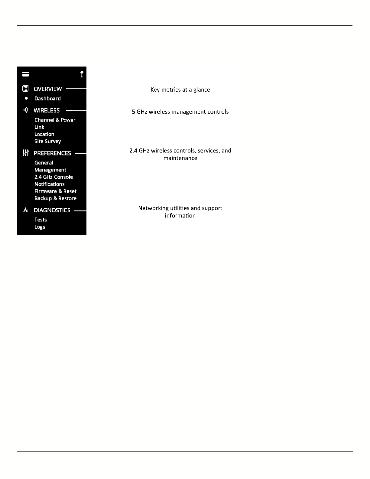
On the left navigation pane, there are four prominent sections: Overview, Wireless, Preferences, and Diagnostics.
Each of these sections contains one or more links to pages containing task-related data, controls, and tools used to
administer the radio…and you can return the Dashboard at any time by clicking on the Dashboard link in the
Overview section.
The pin in the top corner of the left navigation pane allows you to "pin" open the navigation menu for easier access.
Else, the menu contracts to provide more workspace within the GUI. Note that the 2.4 GHz Console menu item is not
B11 User Guide
Mimosa Networks Help Site Overview
Copyright © 2015 Mimosa Page 4
present on the B5-Lite.
B11 User Guide
Mimosa Networks Help Site Dashboard
Copyright © 2015 Mimosa Page 5
The Dashboard
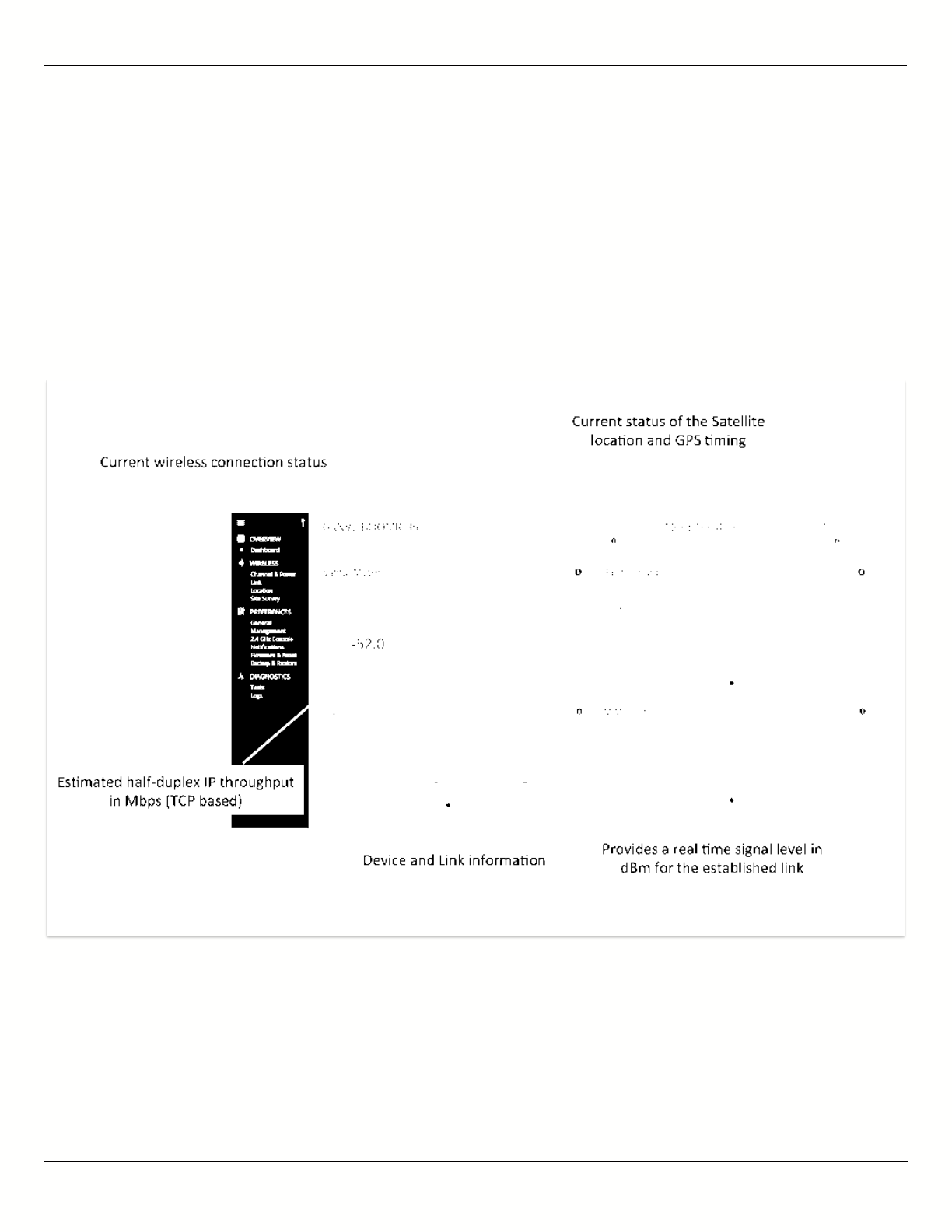
The Dashboard contains several panels used to group related items. The status panel at the top of the page shows
the link SSID, the link status, GPS signal quality*, Link Uptime since association, and Link Availability since the last
reboot. Two of the values on this panel contain an information icon that shows more information when you click or
hover over it with your mouse cursor. On other panels, detailed help text can be found by clicking on the
information icon in the upper right hand corner.
* Applies to B5/B5c and B11 only; does not apply to B5-Lite.

B11 User Guide
Mimosa Networks Help Site Dashboard
Copyright © 2015 Mimosa Page 6
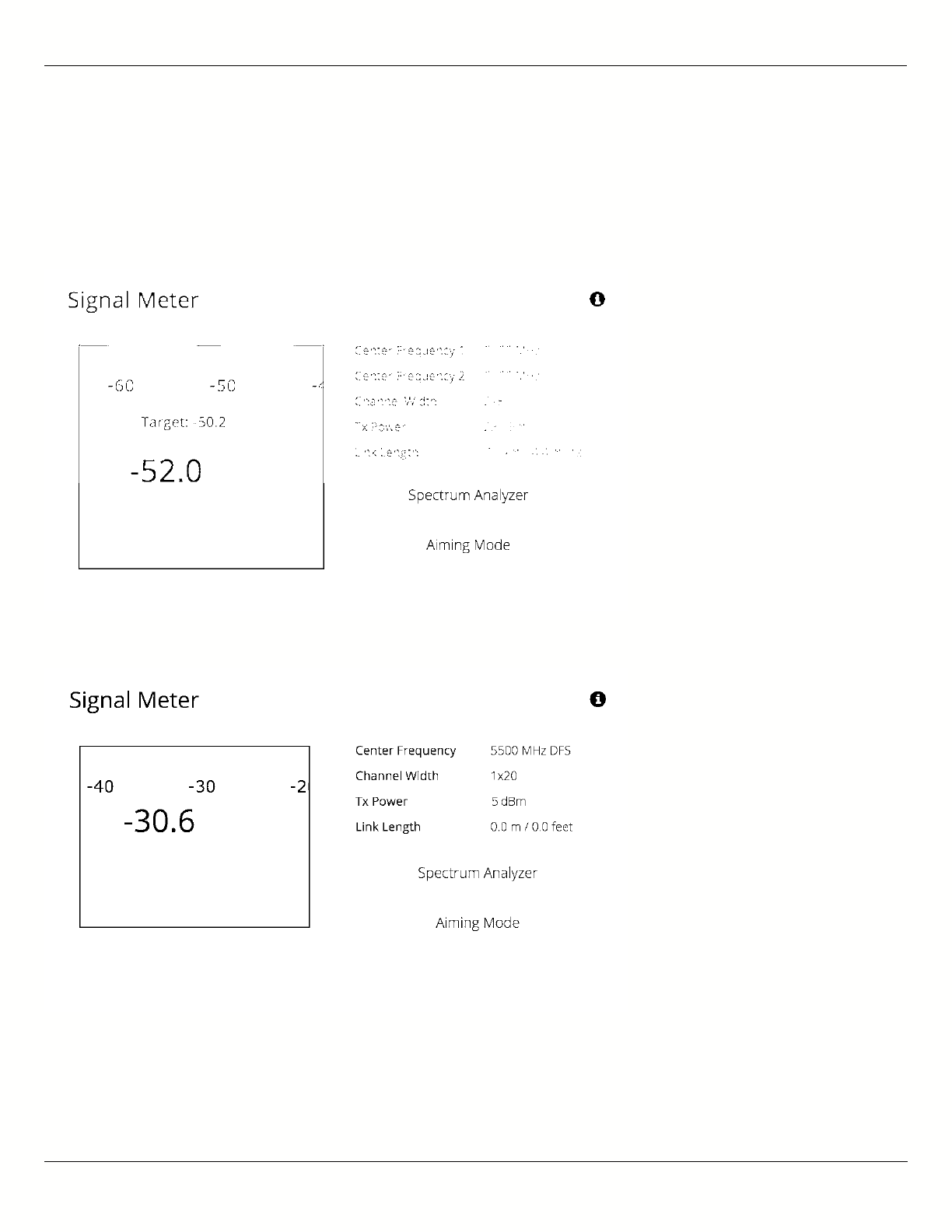
Reading the Signal Meter
Connected Link
Received signal strength is shown in large text in the center of the control, and as a green indicator in the top dial.
The blue shaded bar and text immediately below the dial represent target signal strength based on distance and
other information exchanged between radios. The objective is to align the green indicator with the blue bar as a
guideline during antenna aiming.
The resulting half-duplex PHY rates shown at the bottom of the Signal Meter control are correlated with the MCS,
and represent raw data across the link without protocol overhead. The Max Throughput values include TDMA
window size and MAC layer efficiency.
The following settings and values that affect link health are listed for reference:
B5/B5c
Channel 1 Center Frequency: True center of the first frequency range (no offset).
●
Channel 2 Center Frequency: True center of the second frequency range (no offset).
●
Channel Width: Number of channels used (1 or 2), and the width of each channel (20, 40 or 80 MHz).
●
Tx Power: Total transmit power level (dBm).
●
Link Length: Distance between local and remote radios (when connected).
●
B5-Lite
Center Frequency: True center of the frequency range (no offset).
●
Channel Width: The width of the channel (20, 40 or 80 MHz).
●
Tx Power: Total transmit power level (dBm).
●
Link Length: Distance between local and remote radios (when connected).
●
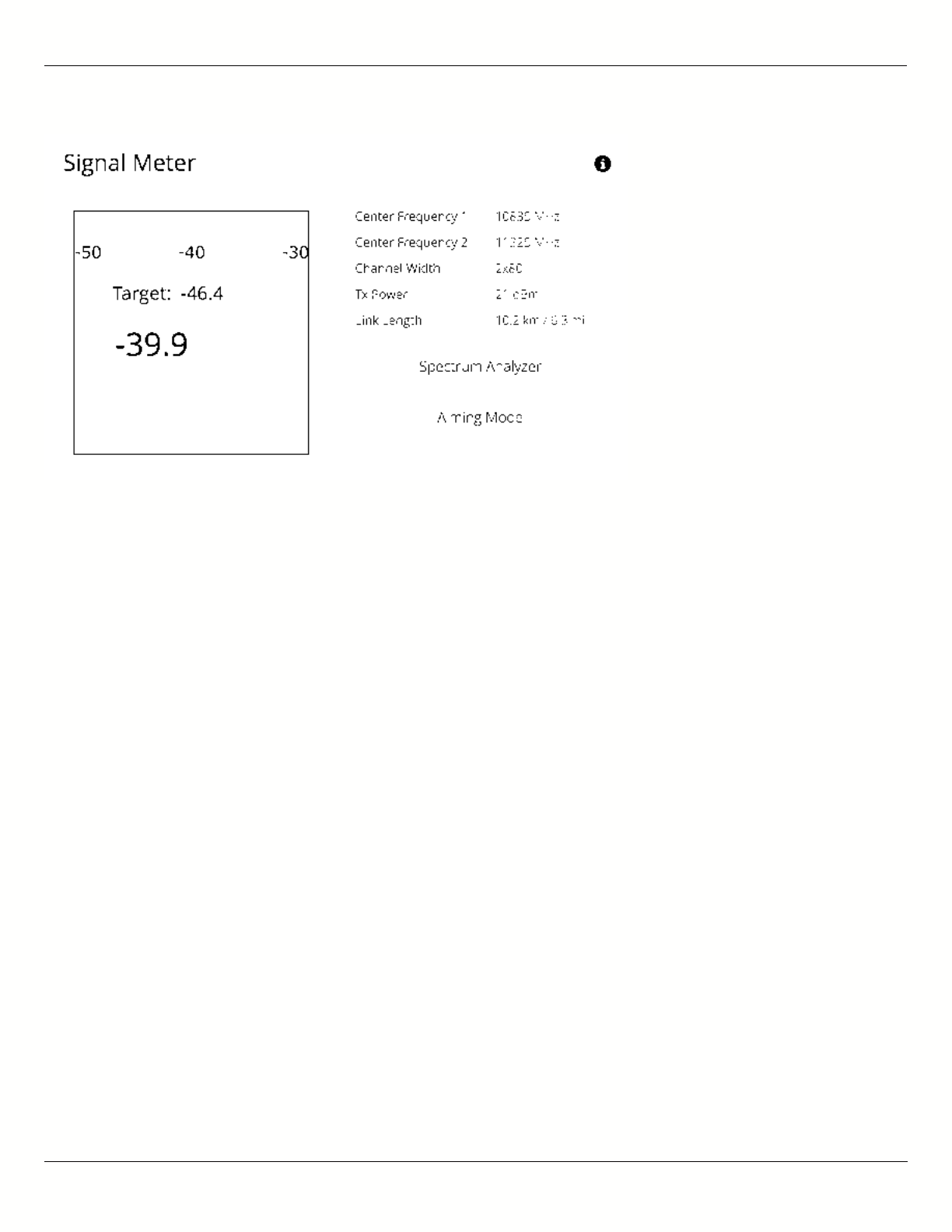
B11
Center Frequency 1: True center of the first frequency range (no offset).
●
Center Frequency 2: True center of the second frequency range (no offset).
●
Channel Width: Number of channels used (1 or 2), and the width of each channel (20, 40 or 80 MHz).
●
Tx Power: Total transmit power level (dBm).
●
Link Length: Distance between local and remote radios (when connected).
●
Click the Spectrum Analyzer button to access the Spectrum Analyzer, which can also be found on the Channel &
Power page. This will not disturb the link.
When a link is not associated, the signal strength and PHY rates are replaced by an indicator of "Disconnected".
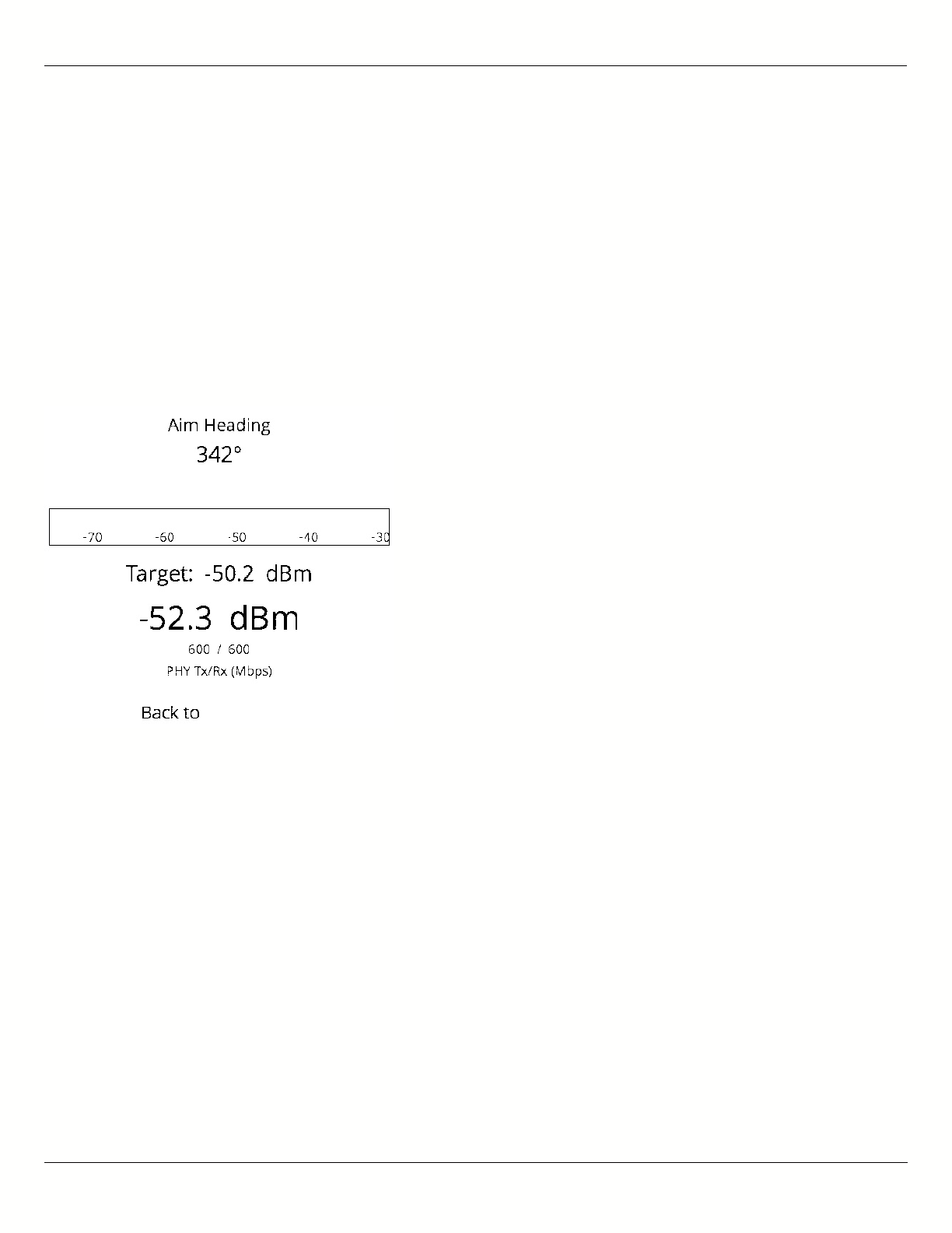
Once associated, click the Aiming Mode button on the Dashboard to open a new window that refreshes once per
second for a 5-minute period. The Aim Heading indicates the direction in which the front of the device should be
B11 User Guide
Mimosa Networks Help Site Dashboard
Copyright © 2015 Mimosa Page 7
pointed based exchange of coordinates. The green arrow and blue shaded region on the dial indicator represent
current and target signal levels, respectively. Note that the dial indicator does not represent azimuth. Azimuth may
need to be adjusted in either direction to meet the target.
B5/B5c Signal Meter
B5-Lite Signal Meter
B11 Signal Meter
B11 User Guide
Mimosa Networks Help Site Dashboard
Copyright © 2015 Mimosa Page 8
B11 User Guide
Mimosa Networks Help Site Dashboard
Copyright © 2015 Mimosa Page 9
Antenna Aiming Mode
Once associated, click the Aiming Mode button on the Dashboard to open a new window that refreshes once per
second for a 5-minute period. The Aim Heading indicates the direction in which the front of the device should be
pointed based exchange of coordinates. The green arrow and blue shaded region on the dial indicator represent
current and target signal levels, respectively. Note that the dial indicator does not represent azimuth. Azimuth may
need to be adjusted in either direction to meet the target.
Note that the target signal level will be incorrect if the antenna gain value is inaccurate (B5c).
Note that the target signal level will be incorrect if the antenna gain value is inaccurate (B5c).
Antenna Aiming Procedure
While viewing the Aiming Mode screen, move the local antenna on one axis at a time (first azimuth and then1.
elevation) in 6mm (1/4 inch) increments.
Wait 2-3 seconds for the signal to settle after each movement. Signal strength may increase or decrease after2.
each movement. Increases in signal strength will move the green arrow and blue shaded region closer
together. Decreases in signal strength will move them farther apart. The point of maximum signal strength
indicates optimal antenna alignment for each axis.
Repeat the steps 1 and 2 above on the remote antenna. The signal strength should match the outputs from3.
the Mimosa Design application. If not, please consult the Low Rx Power troubleshooting guide.

B11 User Guide
Mimosa Networks Help Site Dashboard
Copyright © 2015 Mimosa Page 10
Tip: Use a pen (or a piece of tape) to place an alignment mark on both the antenna mount and the
Tip: Use a pen (or a piece of tape) to place an alignment mark on both the antenna mount and the
mounting pole. The gap between the marks will serve as a visual aid to show how far the antenna has
mounting pole. The gap between the marks will serve as a visual aid to show how far the antenna has
turned in either direction.
turned in either direction.
B11 User Guide
Mimosa Networks Help Site Dashboard
Copyright © 2015 Mimosa Page 11
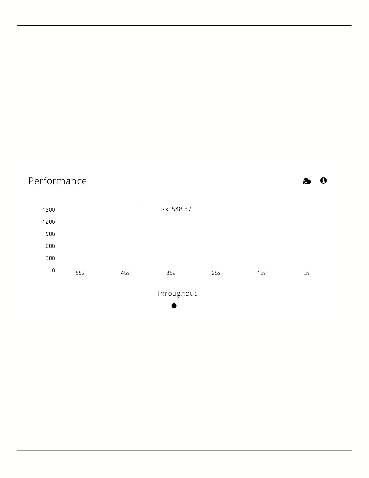
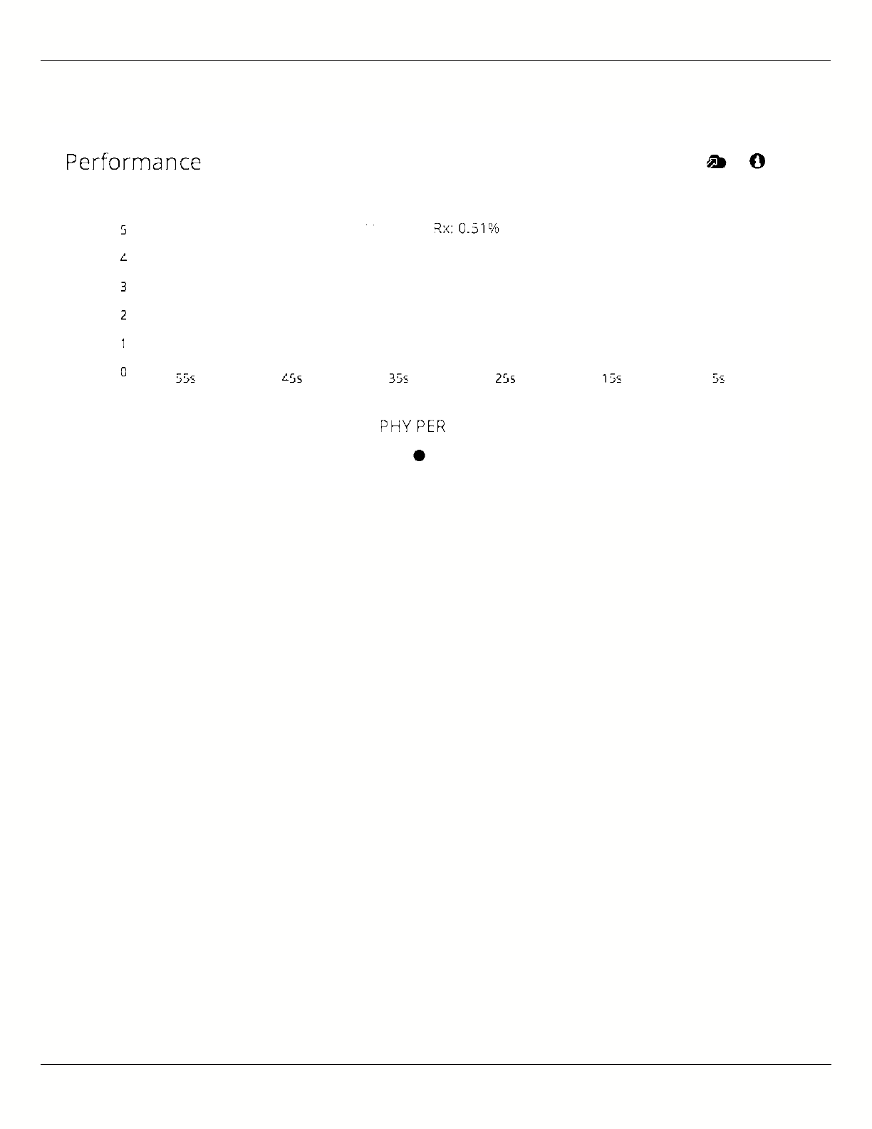
Reading the Performance Charts
IP Throughput and Packet Error Rate (PER) are charted over 60 seconds in 5-second intervals. The newest data
shows up on the right and scrolls to the left over time. You can toggle between the charts by clicking on the
navigation circles at the bottom of the panel. If enabled, click on the cloud icon to view historical data within the
Manage application.
The IP Throughput graph plots three lines representing transmit, receive, and aggregate (summed) throughputs at
the datagram (or packet) layer excluding any protocol or encapsulation overhead. The results here may differ from
those measured using speed test tools, due to protocol overhead and encapsulation. Note that internal Bandwidth
test results are excluded.
The Packet Error Rate (PER) is the number of packets with errors divided by the total number of packets sent within
a 5-second period. Ideally, this value should be below 2%, while higher values indicate the presence of interference.
Tx PER is an indication that the local radio did not receive an ACK from the remote radio, so is forced to retransmit
the same information again. Rx PER is a value sent from the remote radio to the local radio in management frames.
B11 User Guide
Mimosa Networks Help Site Dashboard
Copyright © 2015 Mimosa Page 12
Note: PER will be higher upon initial association, and will usually settle within 30-60 seconds. This is
Note: PER will be higher upon initial association, and will usually settle within 30-60 seconds. This is
because association requires that the radios “listen” more carefully for their link partner until they are
because association requires that the radios “listen” more carefully for their link partner until they are
linked, and this listening period is subject to more interference until Automatic Gain Control (AGC) and
linked, and this listening period is subject to more interference until Automatic Gain Control (AGC) and
Rate Adaptation (RA) adjust parameters to accommodate the conditions. PER values are exchanged
Rate Adaptation (RA) adjust parameters to accommodate the conditions. PER values are exchanged
between radios asynchronously, so the values may not match exactly when referencing both radios at the
between radios asynchronously, so the values may not match exactly when referencing both radios at the
same time.
same time.

B11 User Guide
Mimosa Networks Help Site Dashboard
Copyright © 2015 Mimosa Page 13
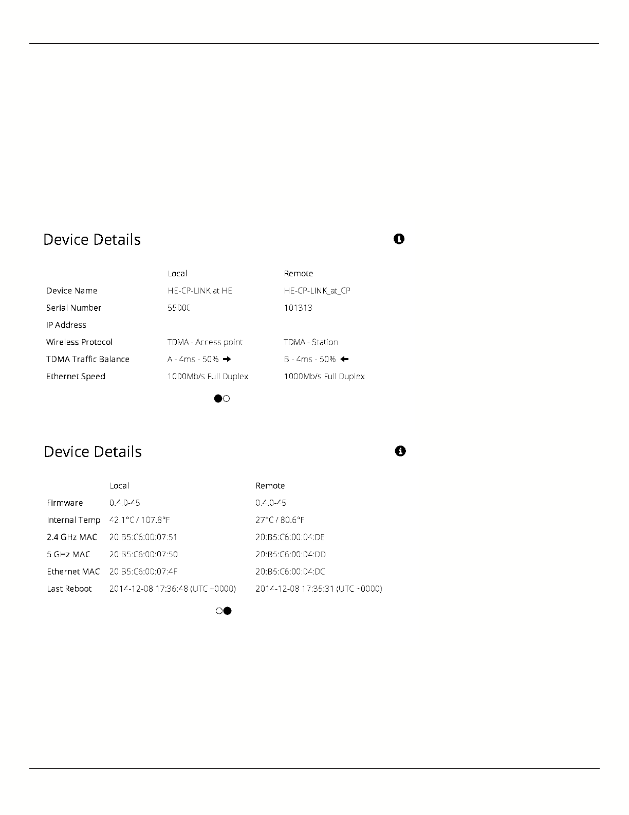
Reading Device Details
The Device Details panel shows two summary tables for the local and remote device configurations and their status.
Click on the navigation circles at the bottom of the panel to toggle between the two tables.
The table shows the following for both Local and Remote devices:
B5/B5c
Device Name: The friendly name given to each device. (Set in Preferences > General > Naming)
●
Serial Number: The unique identifier for the device assigned at the factory.
●
IP Address: The IP address of each device and how it was assigned. (Set in Preferences > Management)
●
Wireless Protocol: The MAC level protocol. (Set in Wireless > Link > MAC Configuration)
●
TDMA Traffic Balance: Identifies the "gender" of the radio, the duration for each TDMA time slot, and ratio of
●
bandwidth allocated for transmission. (Set in Wireless > Link > MAC Configuration)
Ethernet Speed: Data rate and duplex mode of the wired Ethernet interface.
●
Firmware: The latest firmware version applied to each device. (Set in Preferences > Update & Reboot)
●
Internal Temp: Temperature inside the device casing (operating range: -40 °C to +60 °C).
●
2.4 GHz MAC: The unique identifier for the 2.4 GHz radio.
●
5 GHz MAC: The unique identifier for the 5 GHz radio.
●
Ethernet MAC: The unique identifier for the physical Ethernet interface.
●
Last Reboot: The date and time at which each device last rebooted.
●
B5-Lite
Device Name: The friendly name given to each device. (Set in Preferences > General > Naming)
●
Serial Number: The unique identifier for the device assigned at the factory.
●
IP Address: The IP address of each device and how it was assigned. (Set in Preferences > Management)
●
Wireless Protocol: The MAC level protocol. (Set in Wireless > Link > MAC Configuration)
●
TDMA Traffic Balance: Identifies the "gender" of the radio, the duration for each TDMA time slot, and ratio of
●
bandwidth allocated for transmission. (Set in Wireless > Link > MAC Configuration)
Ethernet Speed: Data rate and duplex mode of the wired Ethernet interface.
●
Firmware: The latest firmware version applied to each device. (Set in Preferences > Update & Reboot)
●
CPU Temp: Temperature on the device CPU (operating range: -40 °C to +110 °C).
●
5 GHz MAC: The unique identifier for the 5 GHz radio.
●
Ethernet MAC: The unique identifier for the physical Ethernet interface.
●
Last Reboot: The date and time at which each device last rebooted.
●
B11
Device Name: The friendly name given to each device. (Set in Preferences > General > Naming)
●
Serial Number: The unique identifier for the device assigned at the factory.
●
IP Address: The IP address of each device and how it was assigned. (Set in Preferences > Management)
●
Wireless Protocol: The MAC level protocol. (Set in Wireless > Link > MAC Configuration)
●
TDMA Traffic Balance: Identifies the "gender" of the radio, the duration for each TDMA time slot, and ratio of
●
B11 User Guide
Mimosa Networks Help Site Dashboard
Copyright © 2015 Mimosa Page 14
bandwidth allocated for transmission. (Set in Wireless > Link > MAC Configuration)
Ethernet Speed: Data rate and duplex mode of the wired Ethernet interface.
●
Network Interface: Shows port status; "Ethernet", "Fiber" or "Down".
●
Firmware: The latest firmware version applied to each device (Set in Preferences > Update & Reboot).
●
Internal Temp: Temperature inside the device casing (operating range: -40 °C to +60 °C).
●
5 GHz MAC: The unique identifier for the 5 GHz radio.
●
Ethernet MAC: The unique identifier for the physical Ethernet interface.
●
Last Reboot: The date and time at which each device last rebooted.
●
B11 User Guide
Mimosa Networks Help Site Dashboard
Copyright © 2015 Mimosa Page 15
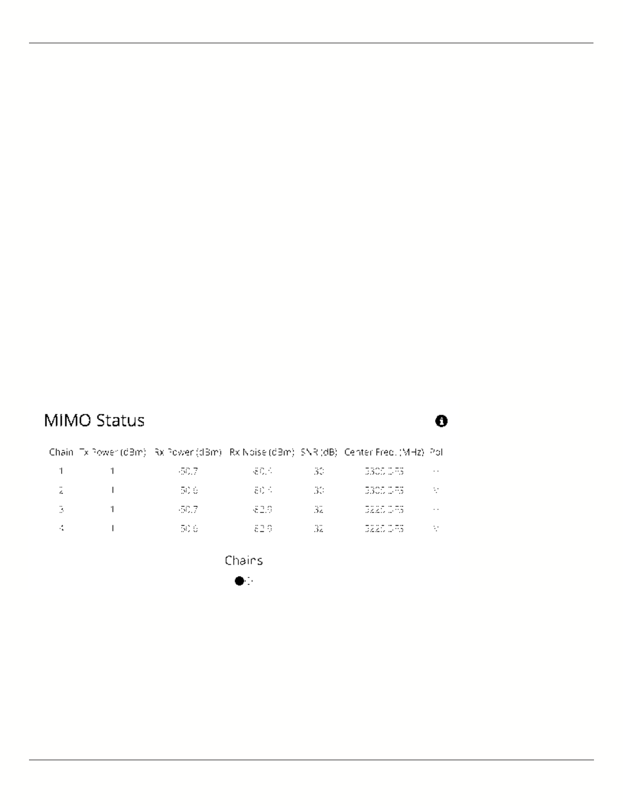
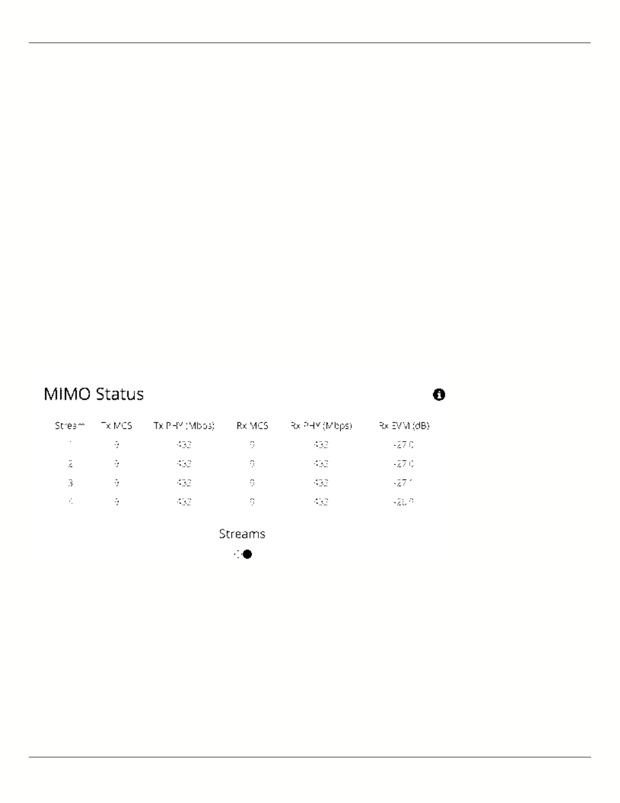
Reading MIMO Status Tables
The MIMO Status panel contains two tables: Chains and Streams. Chains represent the physical medium (RF Tx/Rx
values), while Streams represent data. Chains and Streams are not necessarily correlated one to one because the
Rate Adaptation algorithm may periodically increase or decrease the number of data streams sent over the physical
medium when reacting to interference.
The Chains table describes each chain's power, noise, SNR, frequency and polarization.
The Streams table describes each stream's MCS index, PHY rates and Rx Error Vector Magnitude (EVM).
Each table can be selected by clicking on the navigation circles at the bottom of the panel.
Chains
The Chains table contains 6 values: Tx Power, Rx Power, Rx Noise, SNR, Center Frequency and Polarization. Each
channel is assigned two chains (horizontal and vertical). If two channels are selected, Channel 1 uses Chains 1 & 2,
while Channel 2 uses Chains 3 & 4.
Tx Power is the amount of power applied to each of the MIMO chains.
Tx Power can be shared evenly (preferred), or unevenly (if necessary), between channels. The Tx power
Tx Power can be shared evenly (preferred), or unevenly (if necessary), between channels. The Tx power
per channel is divided evenly per chain. Example: 4 dBm Tx power on Channel 1 results in 1 dBm each on
per channel is divided evenly per chain. Example: 4 dBm Tx power on Channel 1 results in 1 dBm each on
Chains 1 & 2.
Chains 1 & 2.
Rx Power is the incoming signal level from the remote radio. Larger values are better (e.g. -50 dBm is better than -
60 dBm).
Rx Noise is a combination of the thermal noise floor plus interference detected by the local radio. Smaller values are
B11 User Guide
Mimosa Networks Help Site Dashboard
Copyright © 2015 Mimosa Page 16
better (e.g. -90 dBm is better than -80 dBm). Noise sources can be either in close proximity to the local radio, or
they can be remote transmitters pointed back at the local radio.
The signal-to-noise ratio (SNR) is the difference between the Rx Power and Rx Noise, and is a measure of how well
the local receiver can detect signals from the remote transmitter and clearly discern them from noise. Higher
values are better (e.g. 30 dB is better than 10 dB).
If two channels are selected, you may observe that SNR is much lower on one channel than the other. This could be
because the Tx Power is set lower on the remote transmitter, or because of higher interference levels on the
channel. To resolve this, increase Tx Power or change the channel that has lower SNR.
Chains 1 & 3 have horizontal polarization, and Chains 2 & 4 have vertical polarization. Chains with the same
polarization are combined internal to the radio before exiting to the antenna connectors.
Streams
The Streams table contains the Tx MCS index, Tx PHY rate, Rx MCS index, Rx PHY rate, and the Rx EVM for each
stream.
The Tx MCS is an indicator of how well the remote radio can receive data from the local transmitter. The Rx MCS
indicates how well the local radio is receiving data from the remote transmitter.
The Modulation Coding Scheme (MCS) represents how much data can be sent at a time, so directly affects
The Modulation Coding Scheme (MCS) represents how much data can be sent at a time, so directly affects
potential throughput represented by the PHY rate. The higher the MCS index (ranging from 0-9), the more
potential throughput represented by the PHY rate. The higher the MCS index (ranging from 0-9), the more
data that can be sent per transmission. A disadvantages of higher MCS indices is that they require higher
data that can be sent per transmission. A disadvantages of higher MCS indices is that they require higher
SNR since they are more vulnerable to noise.
SNR since they are more vulnerable to noise.
The Error Vector Magnitude (EVM) indicates the difference between the actual and expected amplitude and phase of
an incoming signal. Smaller values are better (e.g. -30 dB is better than -10 dB).
Rate Adaptation dynamically adjusts both the MCS and the number of streams depending on RF conditions. Poor RF

B11 User Guide
Mimosa Networks Help Site Dashboard
Copyright © 2015 Mimosa Page 17
conditions (i.e. interference) causes PER to increase. PER and MCS are inversely correlated meaning that as PER
increases, MCS decreases and vice versa.
Single channel mode usually uses 2 streams, but may drop to one stream if RF conditions are poor. Dual channel
mode uses up to 4 streams. You may also see the number of streams change periodically because of tests that
Rate Adaptation performs to optimize performance. This is expected and normal.
Related:
Backhaul FAQ: What SNR is required for each MCS?
Backhaul FAQ: What is the sensitivity for each MCS index?
Backhaul FAQ: What's a good EVM?
B11 User Guide
Mimosa Networks Help Site Channel & Power
Copyright © 2015 Mimosa Page 18
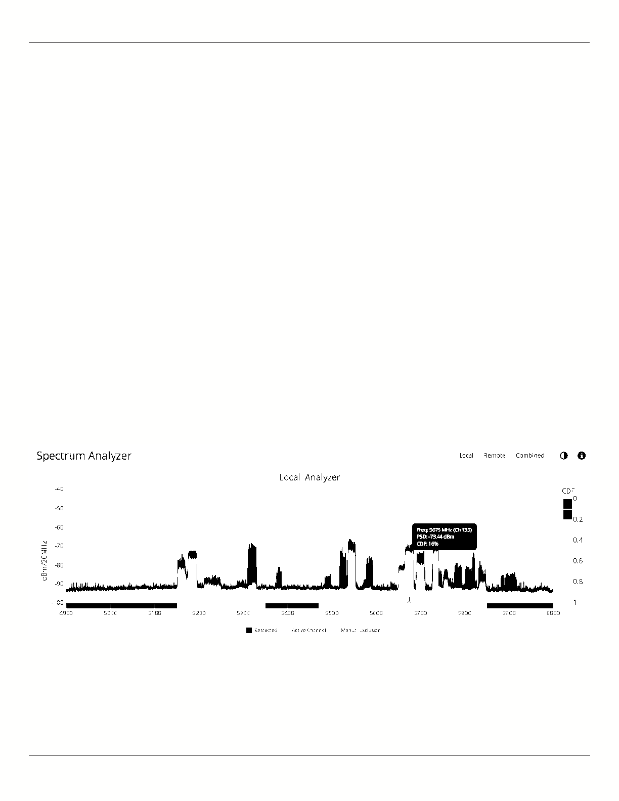
Reading the Spectrum Analyzer
The Spectrum Analyzer actively scans the 5 GHz band in the background to report on interference sources that may
impact link performance. Click the Local, Remote, or Combined buttons to each radio's spectrum individually or
simultaneously. Click on the half circle icon in the upper right to toggle the graph's background color between black
and white. Note that the remote side data may be as much as 5 minutes behind the local radio.
Channels in use have higher Power Spectral Density (PSD) on the vertical axis, and are shaded in different colors to
represent how often the signals are likely to be on the same frequency at the same amplitude.
The legend to the right of the graph explains the color code for the Cumulative Distribution Function (CDF). The
color red suggests the highest probability (1 = 100%), while purple represents the lowest probability (0 = 0%).
Cross hairs appear on the graph beneath the mouse pointer along with an information box containing the frequency
(channel), PSD, and CDF values.
There are three types of markings, or bars, immediately beneath the graph’s horizontal axis that indicate frequency
ranges that are restricted, manually excluded, or in active use by this link. Note that traffic from the Active Channel
is excluded from the display so that noise can be detected.
Note: Buttons on the upper right of the graph show the spectrum for the local radio, the remote radio or a
Note: Buttons on the upper right of the graph show the spectrum for the local radio, the remote radio or a
combined view.
combined view.

B11 User Guide
Mimosa Networks Help Site Channel & Power
Copyright © 2015 Mimosa Page 19
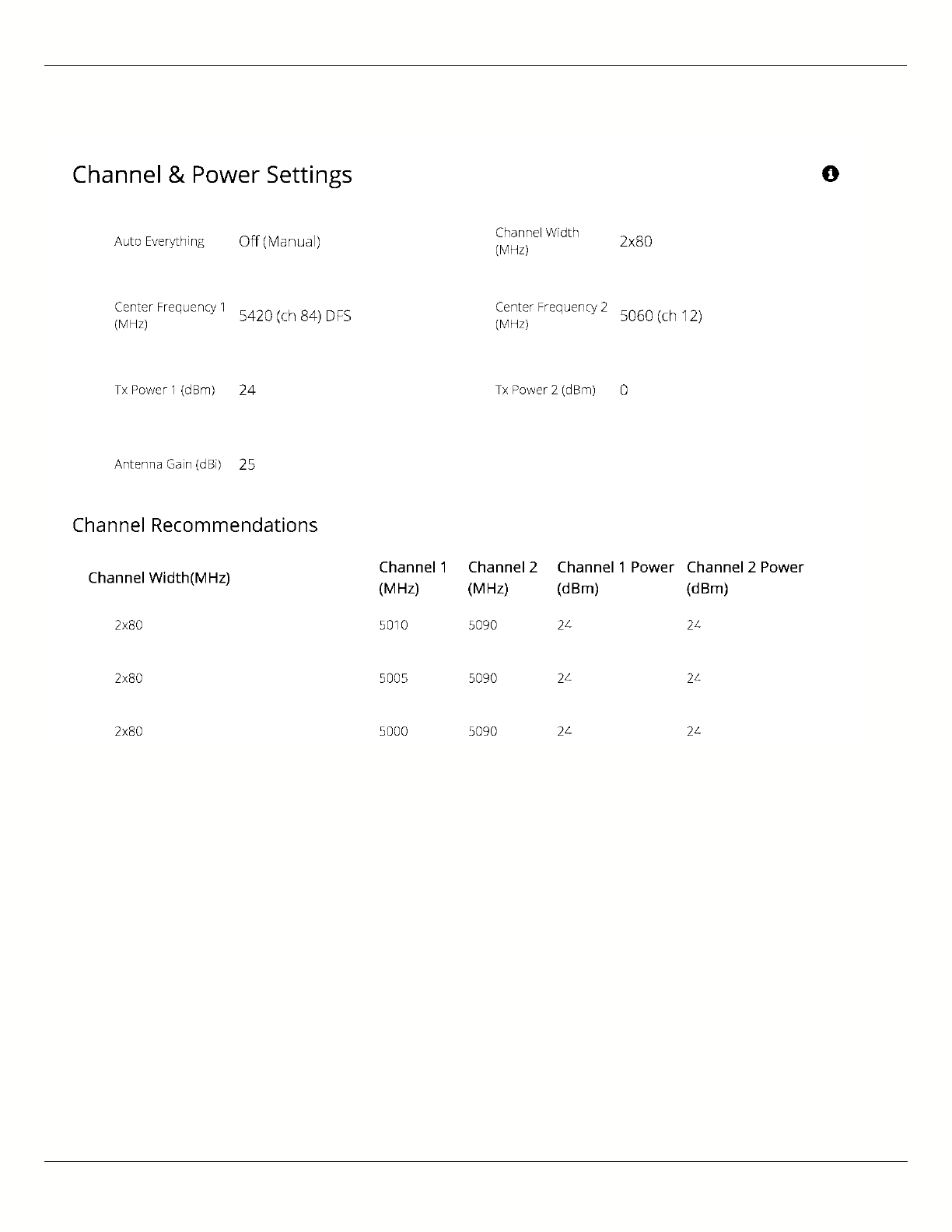
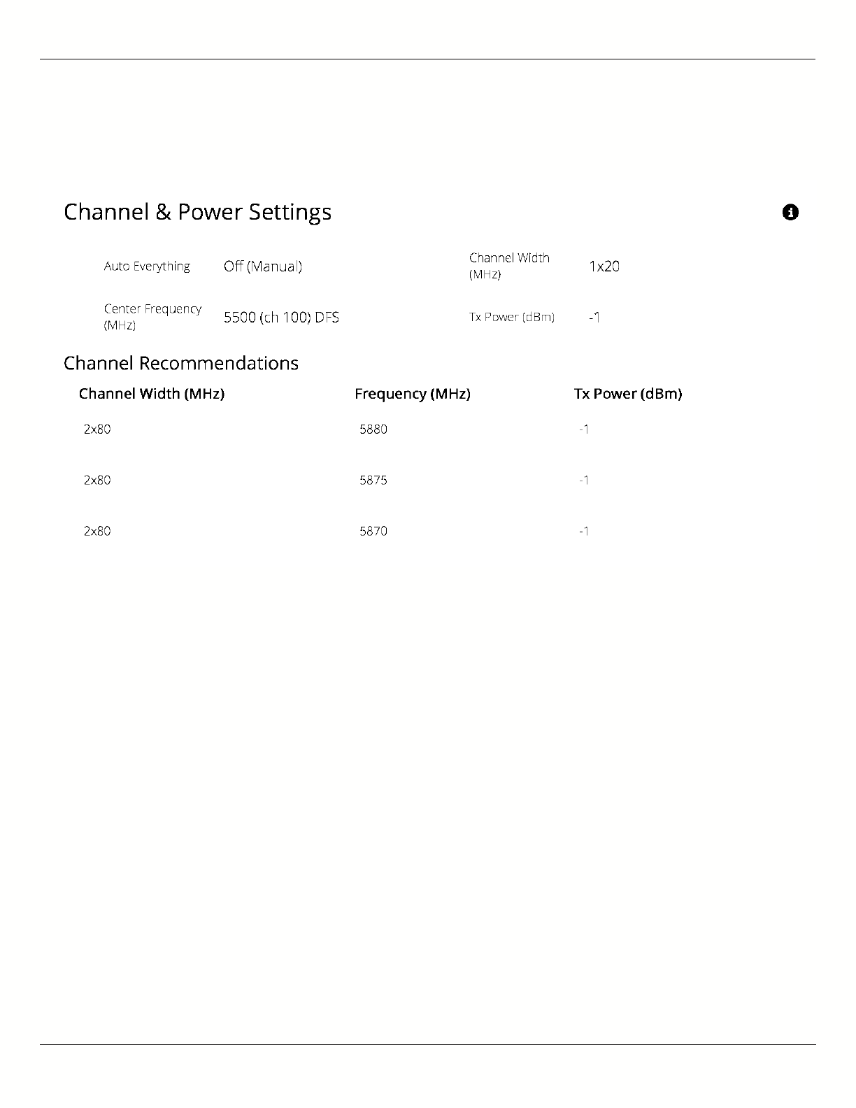
Managing Channel & Power Settings
The Chanel and Power Settings panel allows for either automatic or manual changes to frequency, channel width,
and power for either one or two channels.
B5/B5c
Auto Everything - Automatically configure channel, channel width and power to optimize performance based on
●
spectrum data.
Channel Width (MHz) - In Manual Mode, choose the number of link channels (single or dual) and the
●
channel width for each (Example: 2x80 MHz represents two channels with 80 MHz each, totaling 160 MHz).
Single channel options ending in "FD" allow for different transmit and receive frequencies on Channel 1 & 2,
respectively.
Maximum Channel Width (MHz) - Select the maximum channel width Auto Everything is allowed to use. The
●
decision for single or dual channel modes will be made automatically. For example, selecting 40 MHz as the
maximum channel width may result in 1x40 or 2x20 mode. Smaller channel widths may also be selected based
on RF conditions. Auto Everything is designed to maintain the highest link bandwidth while maintaining link
stability.
Center Frequency (1 & 2) - In Off (Manual) mode, select the center frequency of the channel used on the link. In
●
all modes, the center frequency represents the absolute center of the selected channel width without any
offset, and the center can be moved in 5 MHz increments. If Auto Everything is set to On, the Channel(s) will be
automatically set, and not editable.
Tx Power (1 & 2) - Set the desired transmit power level. The allowed options are determined by a combination
●
of country and chosen frequency. If Channel Width is set to 1xN MHz, Channel 2 will not be used. If Auto
Everything is set to On, Tx Power will be automatically set, and not editable. In "FD" mode, Power 1 and Power 2
represent transmit power on the local and remote sides, respectively.
Antenna Gain (dBi) - Set the gain according to antenna specifications and subtract out any cable/connector
●
loss.
Channel Recommendations - List of channel widths, center frequencies, and Tx powers that Auto Everything
●
would choose in order of preference (if enabled).
B11 User Guide
Mimosa Networks Help Site Channel & Power
Copyright © 2015 Mimosa Page 20
B5-Lite
Auto Everything - Automatically configure channel, channel width and power to optimize performance based on
●
spectrum data.
Channel Width (MHz) - In Manual Mode, choose the channel width (20, 40, or 80 MHz).
●
Maximum Channel Width (MHz) - Select the maximum channel width Auto Everything is allowed to use. The
●
decision for single or dual channel modes will be made automatically. Smaller channel widths may also be
selected based on RF conditions. Auto Everything is designed to maintain the highest link bandwidth while
maintaining link stability.
Center Frequency - In Off (Manual) mode, select the center frequency of the channel used on the link. In all
●
modes, the center frequency represents the absolute center of the selected channel width without any offset,
and the center can be moved in 5 MHz increments. If Auto Everything is set to On, the Channel will be
automatically set, and not editable.
Tx Power - Set the desired transmit power level. The allowed options are determined by a combination of
●
country and chosen frequency. If Auto Everything is set to On, the Channel & Tx Power will be automatically set,
and not editable.
B11 User Guide
Mimosa Networks Help Site Channel & Power
Copyright © 2015 Mimosa Page 21
Channel Recommendations - List of channels, center frequencies, and Tx powers that Auto Everything would
●
choose in order of preference (if enabled).
B11
Auto Everything - Automatically configure channel, channel width and power to optimize performance based on
●
spectrum data. Available only within the 10,000-10,700 MHz Operating Band.
Channel Width (MHz) - In Manual Mode, choose the channel width (20, 40, or 80 MHz).
●
Maximum Channel Width (MHz) - Select the maximum channel width Auto Everything is allowed to use. The
●
decision for single or dual channel modes will be made automatically. Smaller channel widths may also be
selected based on RF conditions. Auto Everything is designed to maintain the highest link bandwidth while
maintaining link stability.
Center Frequency (1 & 2) - In Off (Manual) mode, select the center frequency of the channel used on the link. In
●
all modes, the center frequency represents the absolute center of the selected channel width without any
offset, and the center can be moved in 5 MHz increments. If Auto Everything is set to On, the Channel will be
automatically set, and not editable.
Local and Remote Device Power - Set the desired transmit power levels on the AP. The allowed options are
●
determined by a combination of country and chosen frequency. If Auto Everything is set to On, the Channel &
Tx Power will be automatically set, and not editable.
Antenna Gain (dBi) - Set the gain according to antenna specifications and subtract out any cable/connector
●
loss.
Channel Recommendations - List of channel widths, center frequencies, and Tx powers that Auto Everything
●
would choose in order of preference (if enabled).
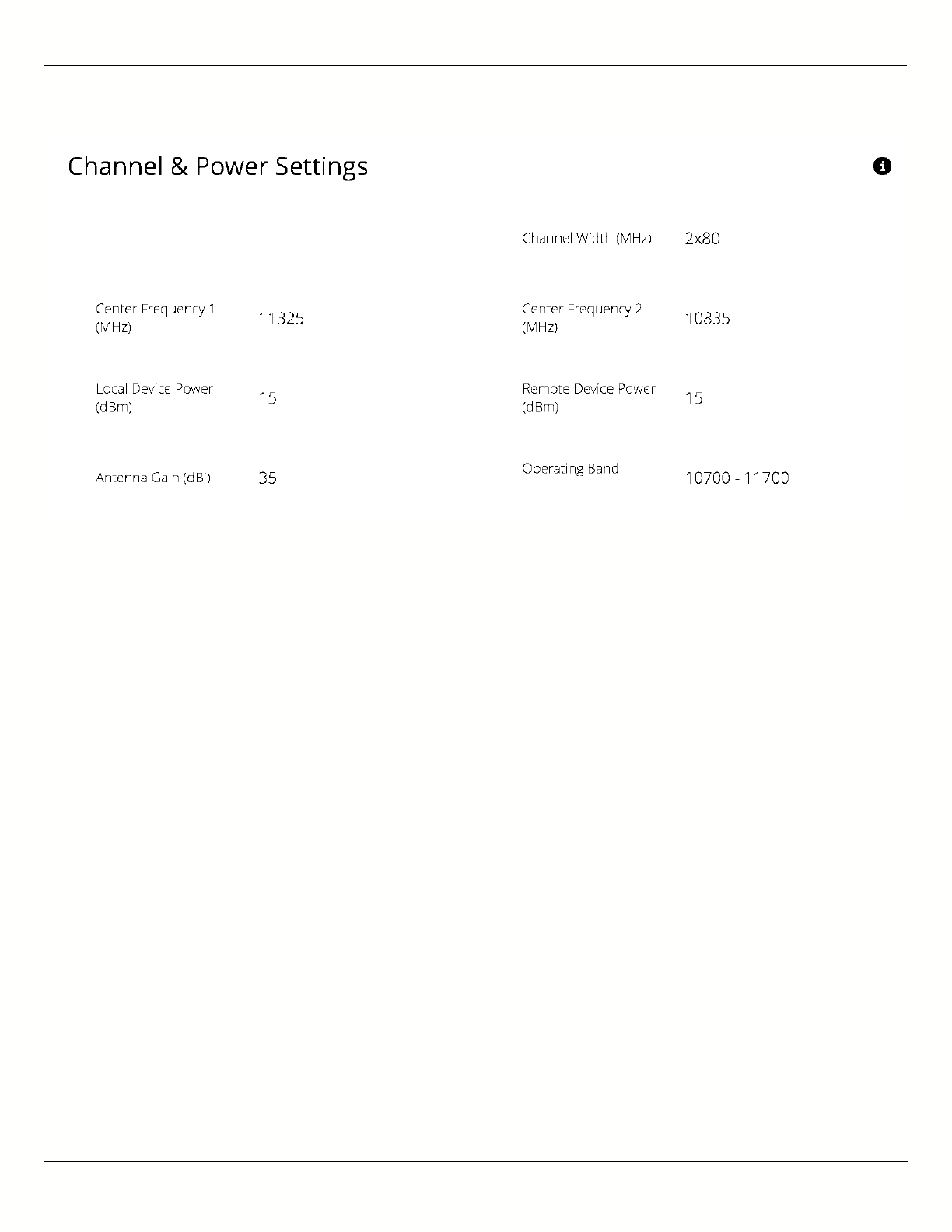
B11 User Guide
Mimosa Networks Help Site Channel & Power
Copyright © 2015 Mimosa Page 22
Note: Tx power selections may be limited based on your regulatory domain (refer to the Maximum Power chart for more details).
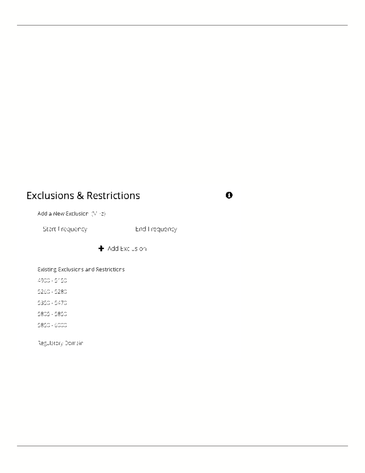
B11 User Guide
Mimosa Networks Help Site Channel & Power
Copyright © 2015 Mimosa Page 23
Managing Exclusions & Restrictions
Exclusions list the frequency ranges in which the device should not operate. The Auto Everything feature will avoid
these frequency bands. The excluded bands will be shown as shaded regions on the Spectrum Analyzer.
Start - Specify the lower limit for the exclusion range, not including this frequency.
●
End - Specify the upper limit for the exclusion range, not including this frequency.
●
Add Exclusions - The button to add the Start and End frequency range to the exclusion list.
●
Existing Exclusions and Restrictions - Exclusions can be removed from the list by clicking on the trash icon. The
●
restricted bands with the lock icon cannot be removed. They are protected because of regulatory requirements.
Regulatory Domain - The country in which the device has been configured to run.
●
In the United States, if either the AP or STA are within a 60 km radius of a Terminal Doppler Weather Radar (TDWR)
location, one or more 30 MHz restrictions are automatically created to avoid the TDWR operating frequencies.

B11 User Guide
Mimosa Networks Help Site Link
Copyright © 2015 Mimosa Page 24
TDMA Configuration Settings
The TDMA Configuration panel contains controls for configuring and fine tuning TDMA performance. One side of the
radio link must be set as an Access point, and the other set as a Station. The Station inherits the other settings from
the AP, so the other fields are grayed out and not accessible when Station is selected.
B5/B5c
Wireless Mode - Choose whether the device will act as an Access Point or a Station.
●
Gender - Traffic Split - The radio can be configured to allocate bandwidth symmetrically (50/50) or biased
●
towards downstream (75/25) in environments where traffic direction is expected to be heavier in one direction
than the other. With an asymmetrical split, the local radio is represented first in the slash notation,
(local/remote). For example, in the (75/25) split, the local radio gets 75, while the remote radio gets 25. If
"Auto" is selected the radio will automatically determine, based upon traffic flow, which ratio will be used. The
radio will continue to evaluate the flow and adjust accordingly.
TDMA Window - Determines the length of the transmit time slot in milliseconds.
●
Note: To enable spectrum reuse, both Gender-Traffic Split and TDMA Window must each be set to the same value for all collocated
radios. Further, "Auto" must not be selected as the TDMA Window when radios are collocated.
B5-Lite
Wireless Mode - Choose whether the device will act as an Access Point or a Station.
●
Traffic Split - The radio can be configured to allocate bandwidth symmetrically (50/50) or biased towards
●
downstream (75/25) in environments where traffic direction is expected to be heavier in one direction than the
other. With an asymmetrical split, the local radio is represented first in the slash notation, (local/remote). For
example, in the (75/25) split, the local radio gets 75, while the remote radio gets 25. If "Auto" is selected the
radio will automatically determine, based upon traffic flow, which ratio will be used. The radio will continue to
evaluate the flow and adjust accordingly.
TDMA Window - Determines the length of the transmit time slot in milliseconds.
●
B11
Wireless Mode - Choose whether the device will act as an Access Point or a Station.
●
Gender - Traffic Split - The radio can be configured to allocate bandwidth symmetrically (50/50) or biased
●
towards downstream (75/25) in environments where traffic direction is expected to be heavier in one direction
than the other. With an asymmetrical split, the local radio is represented first in the slash notation,
(local/remote). For example, in the (75/25) split, the local radio gets 75, while the remote radio gets 25. If
"Auto" is selected the radio will automatically determine, based upon traffic flow, which ratio will be used. The
radio will continue to evaluate the flow and adjust accordingly.
TDMA Window - Determines the length of the transmit time slot in milliseconds.
●
Note: To enable spectrum reuse, both Gender-Traffic Split and TDMA Window must each be set to the same value for all collocated
radios. Further, "Auto" must not be selected as the TDMA Window when radios are collocated.
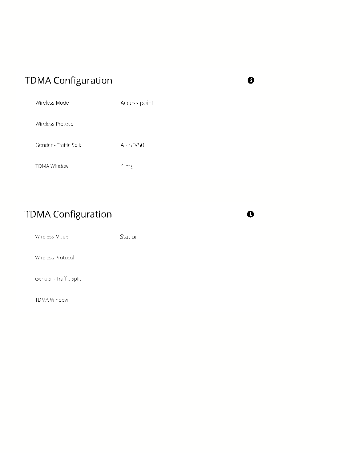
B11 User Guide
Mimosa Networks Help Site Link
Copyright © 2015 Mimosa Page 25
Example Access Point Settings
Example Station Settings
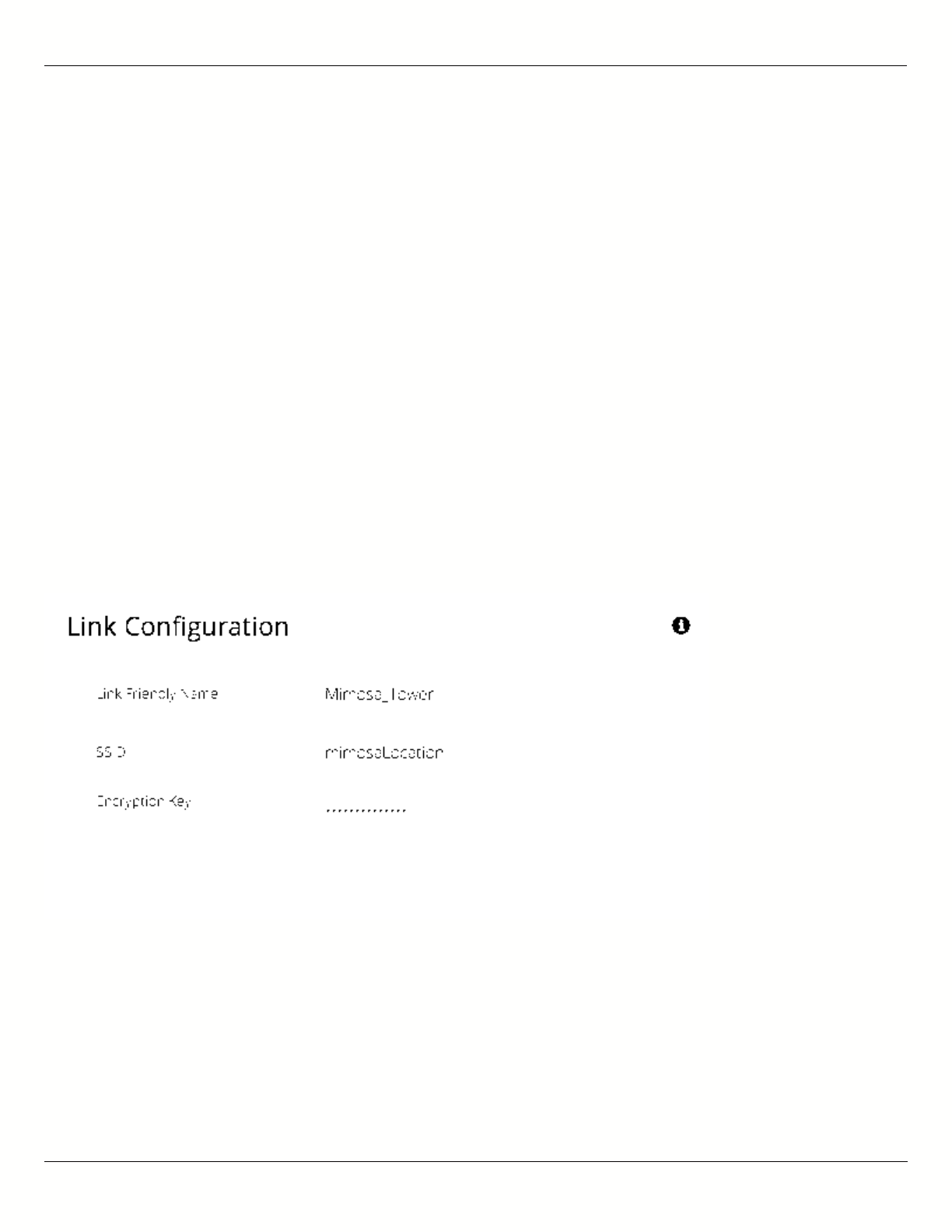
B11 User Guide
Mimosa Networks Help Site Link
Copyright © 2015 Mimosa Page 26
Link Configuration Settings
The Link Configuration panel includes controls to define the 5 GHz SSID and passphrase between radios:
Link Friendly Name - A friendly name to describe the link between the Access Point (AP) and Station. This name
●
is used to differentiate amongst other links.
SSID - The wireless link name used by both radios. Both AP and Station must use the same SSID to
●
communicate with each other.
Encryption Key - Enter the ASCII Passphrase to connect with the broadcasted SSID. Select "Show Key" to see
●
passphrase in plain text. Enter any combination of printable characters. The passphrase should be between 8 to
63 characters in length. The Encryption Key must be the same on both the Access Point and Station for them to
communicate with each other.
Scan for SSID - On a radio configured as a Station, click this button to display a list of Access Point SSIDs.
●
Status - Indicates whether the AP and Station are "Connected" (associated) or "Not Connected" (disassociated).
●
Please ensure that the SSID, Encryption Key, and firmware versions are the same. Additionally, ensure that the IP
addresses are different, and on the same subnet.
Example Access Point Link Configuration
Example Station Link Configuration
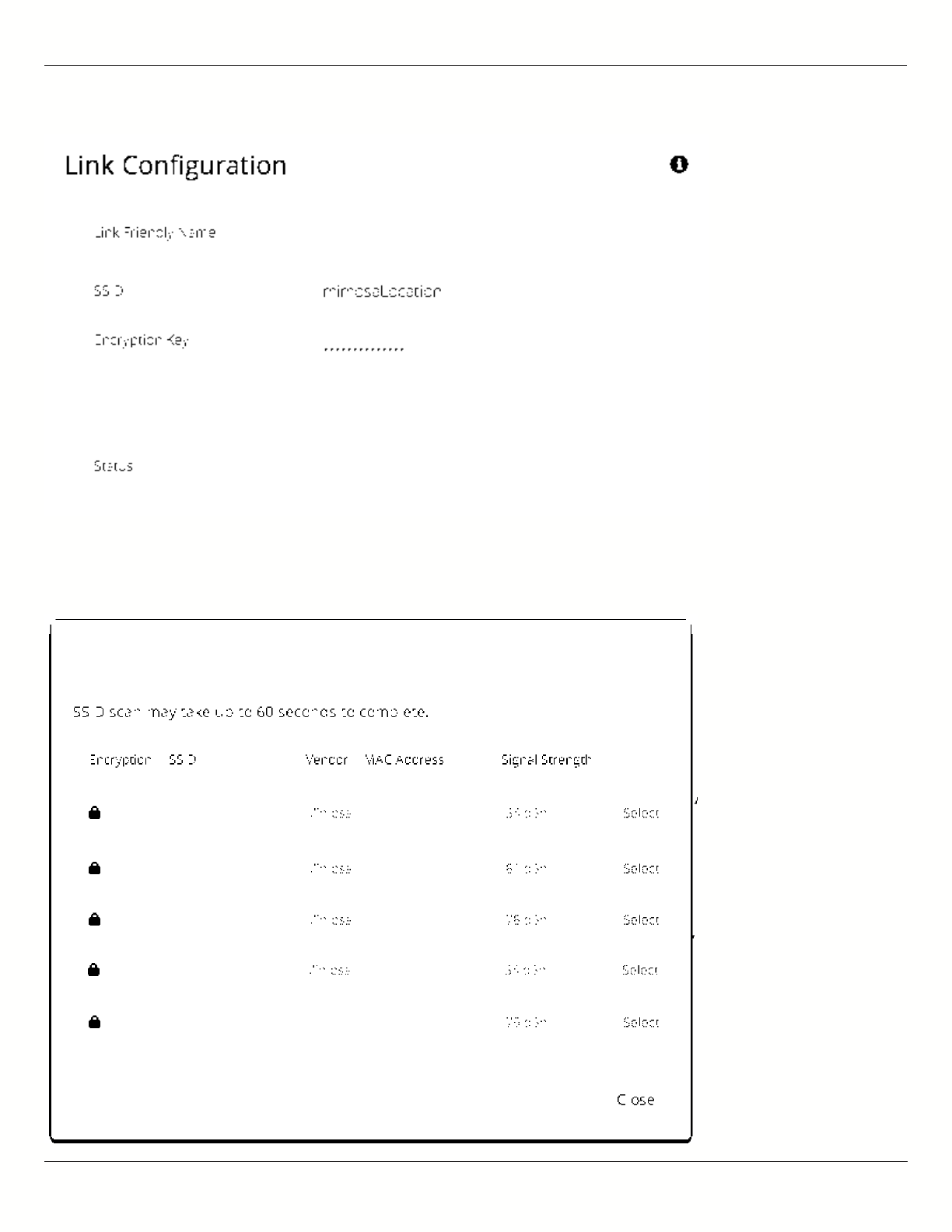
B11 User Guide
Mimosa Networks Help Site Link
Copyright © 2015 Mimosa Page 27
Example SSID Scan after pressing the "Scan SSID" button. To
connect to a particular SSID, click the "Select" button.
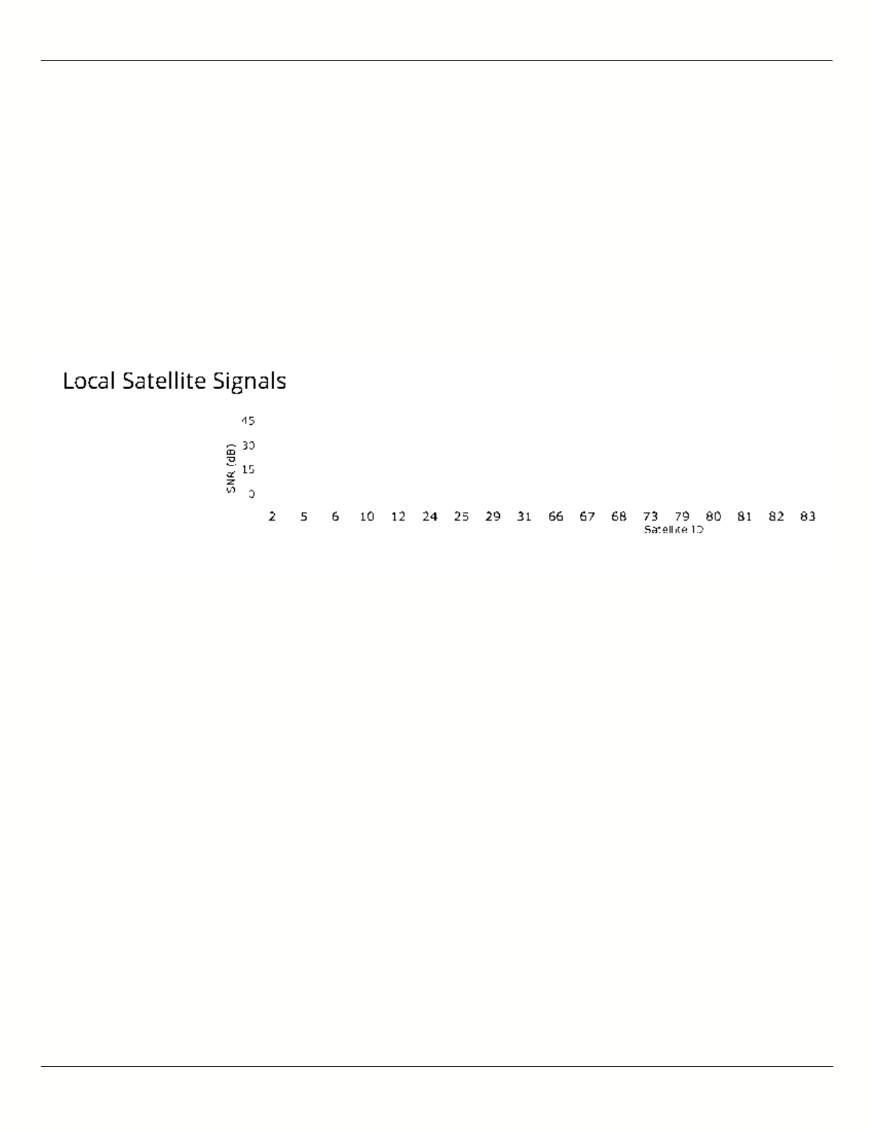
B11 User Guide
Mimosa Networks Help Site Location
Copyright © 2015 Mimosa Page 28
Interpreting Local Satellite Signals
Product Applicability: B5/B5c, B11
The Local Satellite Signals panel contains a chart showing both GPS and GLONASS satellites in blue and green,
respectively, from which the radio can obtain position and timing data used for synchronization. Each numbered
column represents a unique satellite with the columns’ amplitude representing the signal to noise ratio of the
satellite’s signal at the radio’s receiver. The number of satellites the radio detects and the SNR of each both
contribute to clock accuracy.
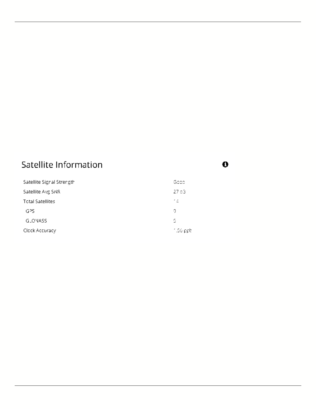
B11 User Guide
Mimosa Networks Help Site Location
Copyright © 2015 Mimosa Page 29
Reading Satellite Information
Product Applicability: B5/B5c, B11
The Satellite Information panel contains values that represent and contribute to clock accuracy. Good GPS signal
strength is required for maximum performance, as the GPS is used to synchronize timing between devices.
Satellite Signal Strength - Qualitative assessment based on all items below; also displayed on the Dashboard.
●
Satellite Avg SNR - Average signal to noise ratio amongst satellites.
●
Total Satellites - Sum of detected GPS and GLONASS satellites.
●
GPS - Number of GPS satellites detected.
●
GLONASS - Number of GLONASS satellites detected.
●
Clock Accuracy - Timing signal accuracy measured in parts per billion (ppb).
●
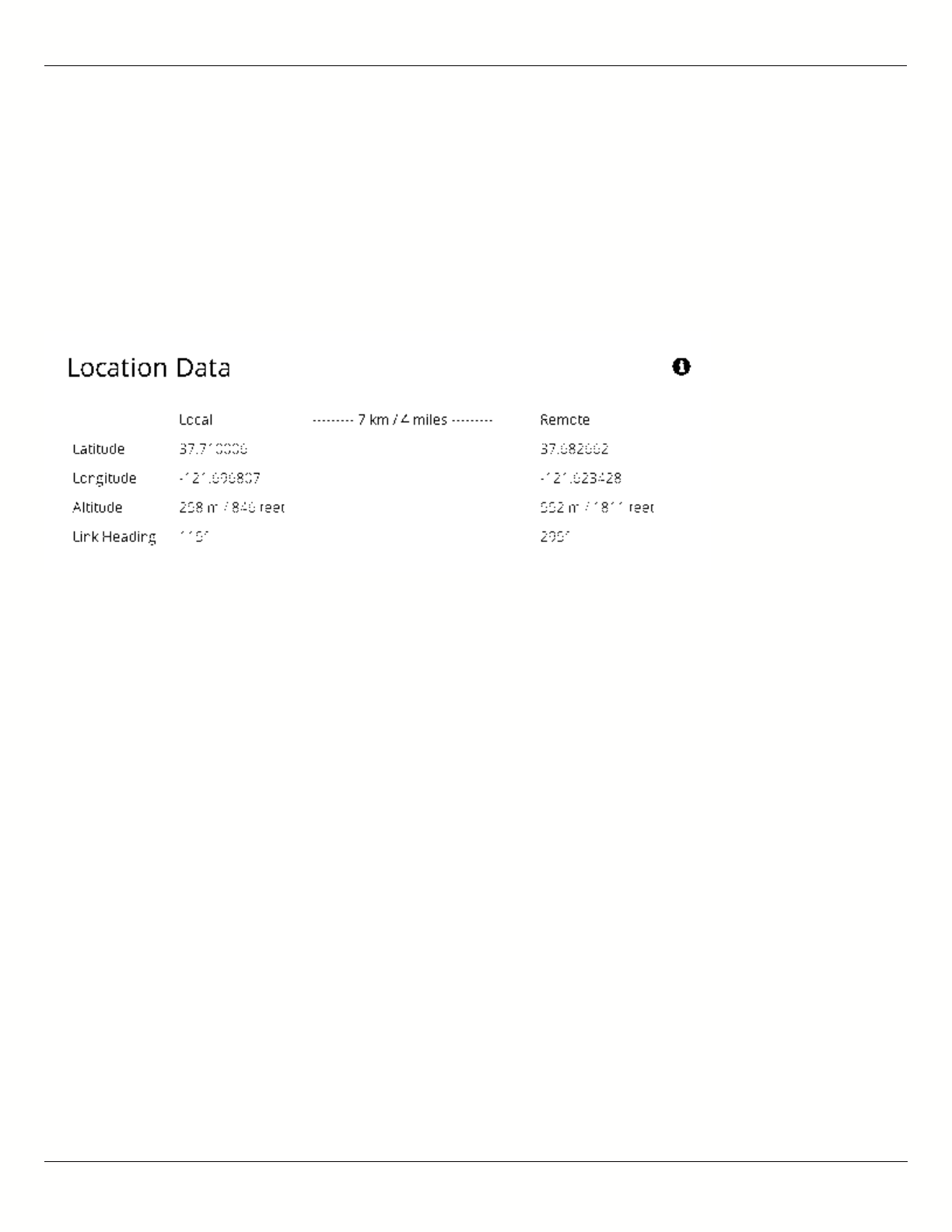
B11 User Guide
Mimosa Networks Help Site Location
Copyright © 2015 Mimosa Page 30
Viewing Location Data
Product Applicability: B5/B5c
Status table showing location, altitude, and heading for both the local and remote devices, as well as the link
distance between them. The link length in the middle of the table will show "Disconnected" if a connection has not
been established.

B11 User Guide
Mimosa Networks Help Site Location
Copyright © 2015 Mimosa Page 31
Local Coordinates
Product Applicability: B5-Lite
Enter the latitude and longitude of the local radio in signed decimal degrees with four digits after the decimal point
(e.g. ##.####). These values are used to calculate distance and propagation delay, to coordinate Auto Everything
within the same subnet, and to display the radios on a map within Mimosa cloud applications.

B11 User Guide
Mimosa Networks Help Site Location
Copyright © 2015 Mimosa Page 32
Remote Coordinates
Product Applicability: B5-Lite
Enter the latitude and longitude of the remote radio in signed decimal degrees with four digits after the decimal
point (e.g. ##.####). These values are used to calculate distance and propagation delay, to coordinate Auto
Everything within the same subnet, and to display the radios on a map within Mimosa cloud applications.

B11 User Guide
Mimosa Networks Help Site Location
Copyright © 2015 Mimosa Page 33
Distance
Product Applicability: B5-Lite
The calculated distance between radios based on the local and remote coordinates. This value is used to calculate
propagation delay.
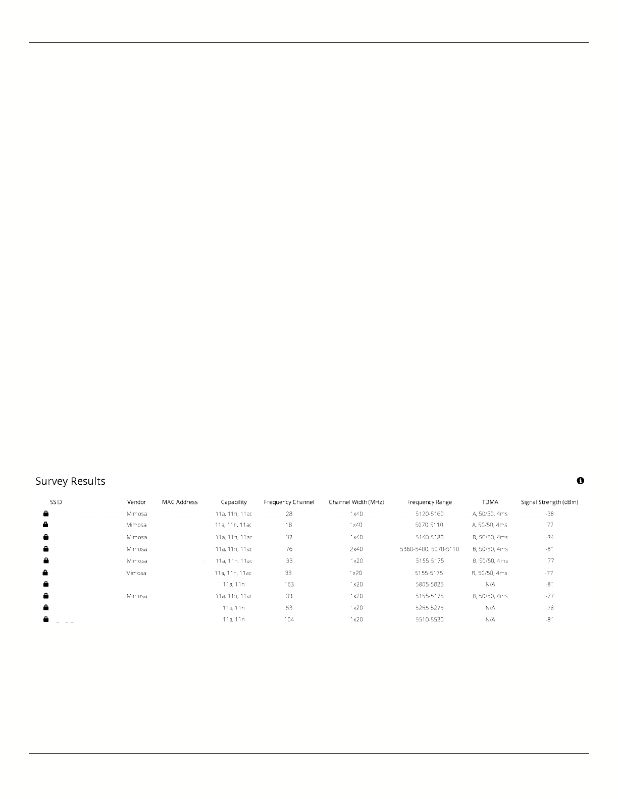
B11 User Guide
Mimosa Networks Help Site Site Survey
Copyright © 2015 Mimosa Page 34
Reading Site Survey Results
The Survey Results status table summarizes the results of a site survey, including the SSIDs broadcast by other
devices, their configuration and capabilities. Note that the Site Survey function is only available on radios configured
as a Station (versus AP).
The table provides the following data per device found:
SSID - The wireless link name advertised by each detected AP.
●
Capability - Indicates which 802.11 (Wi-Fi technology standard) is support by the device. Options include A, G,
●
N, AC.
MAC Address - The device's unique identifier.
●
Vendor - The name of the device manufacturer (if known).
●
Wi-Fi Channel - Lists the channel on which the device operates.
●
Channel Width - The size (in MHz) of the channel on which the device operates.
●
Frequency Range - The specific frequency range (in MHz) within the Wi-Fi channel that the device operates.
●
Signal Strength - The received power level (in dBm) from each detected AP.
●
Note: The Site Survey will temporarily interrupt your link. Once started, this process cannot be stopped until complete.
Use the Start Survey button to place the radio into the scan mode to search for 802.11-compatible access points.
The Last Updated field indicates (down to the second) when the last Site Survey was requested.
It is important to note that running a site survey will temporarily take down your link. Once activated, this process
cannot be stopped until complete. Please plan accordingly.
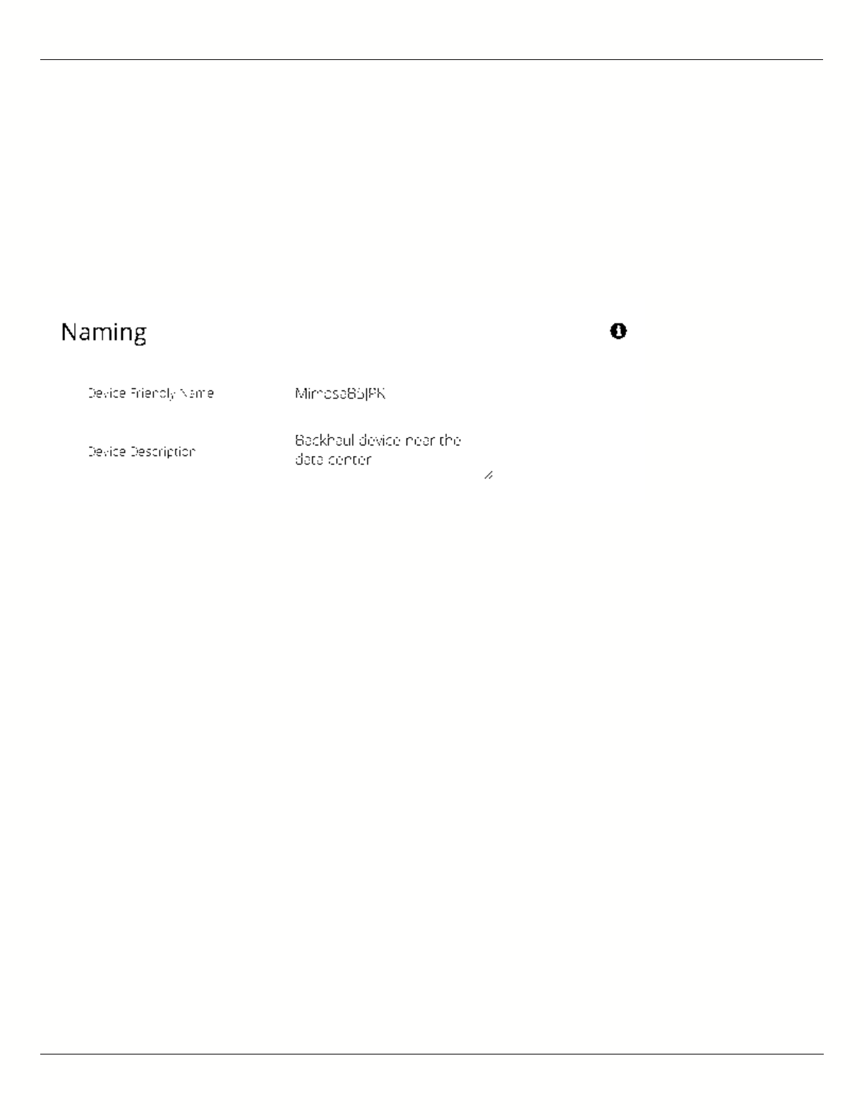
B11 User Guide
Mimosa Networks Help Site General
Copyright © 2015 Mimosa Page 35
Setting a Device Name and Description
The device name and description are local identifiers for administrative purposes, and are not used as part of the
wireless link.
Device Friendly Name - Name for the local device displayed on the Dashboard.
●
Device Description - A more detailed device description (up to 150 characters) for administrative purposes.
●
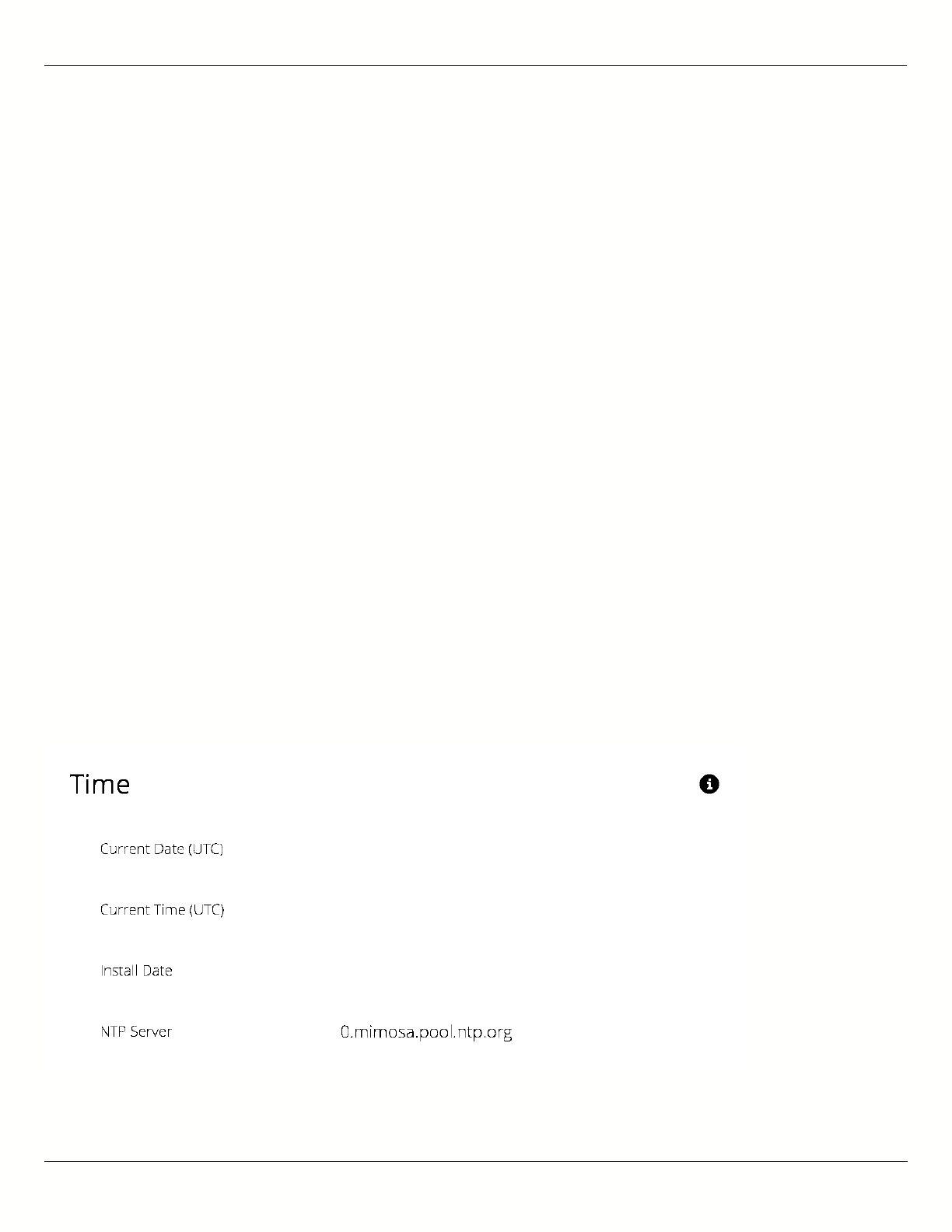
B11 User Guide
Mimosa Networks Help Site General
Copyright © 2015 Mimosa Page 36
Reading the Date/Time & Setting the Install
Date
The Time panel shows the current date and time in Coordinated Universal Time (UTC). The Install Date input box can
be used for administrative purposes, but it is optional and has no other affect.
B5/B5c
Current Date (UTC) - Current date as set by GPS.
●
Current Time (UTC) - Current time as set by GPS.
●
Install Date - Used to track the date that the device was installed.
●
B5-Lite
Current Date (UTC) - Current date as set by the NTP Server.
●
Current Time (UTC) - Current time as set by the NTP Server.
●
Install Date - Used to track the date that the device was installed.
●
NTP Server - Domain name or IP address of network time server.
●
B11
Current Date (UTC) - Current date as set by GPS.
●
Current Time (UTC) - Current time as set by GPS.
●
Install Date - Used to track the date that the device was installed.
●
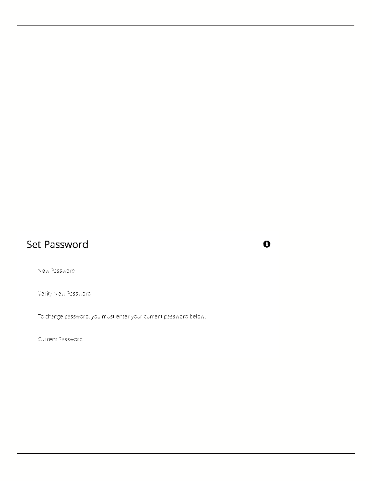
B11 User Guide
Mimosa Networks Help Site General
Copyright © 2015 Mimosa Page 37
Setting a Password
Enter the new password in both the New Password and Verify New Password input boxes to validate that they were
typed correctly. To finalize the change, enter the existing password and then save. The default password should be
changed during device configuration to protect your network.
New Password - Enter the new password.
●
Verify New Password - Re-enter the new password (to confirm).
●
Current Configure Password - Enter the existing password (as a security measure).
●
The Password rules are as follows for choosing a password:
It must be between 6 to 64 characters.
●
It can use capital (A-Z) or lower case (a-z) characters, excluding space.
●
Valid special characters for the password include ! " # $ % & ' ( ) * + , - . / : ; < = > ? [ ] ^ _ ` { | } ~
●
The password cannot be blank.
●
The password may not have a leading or trailing space.
●
There is no complexity required for the password.
●
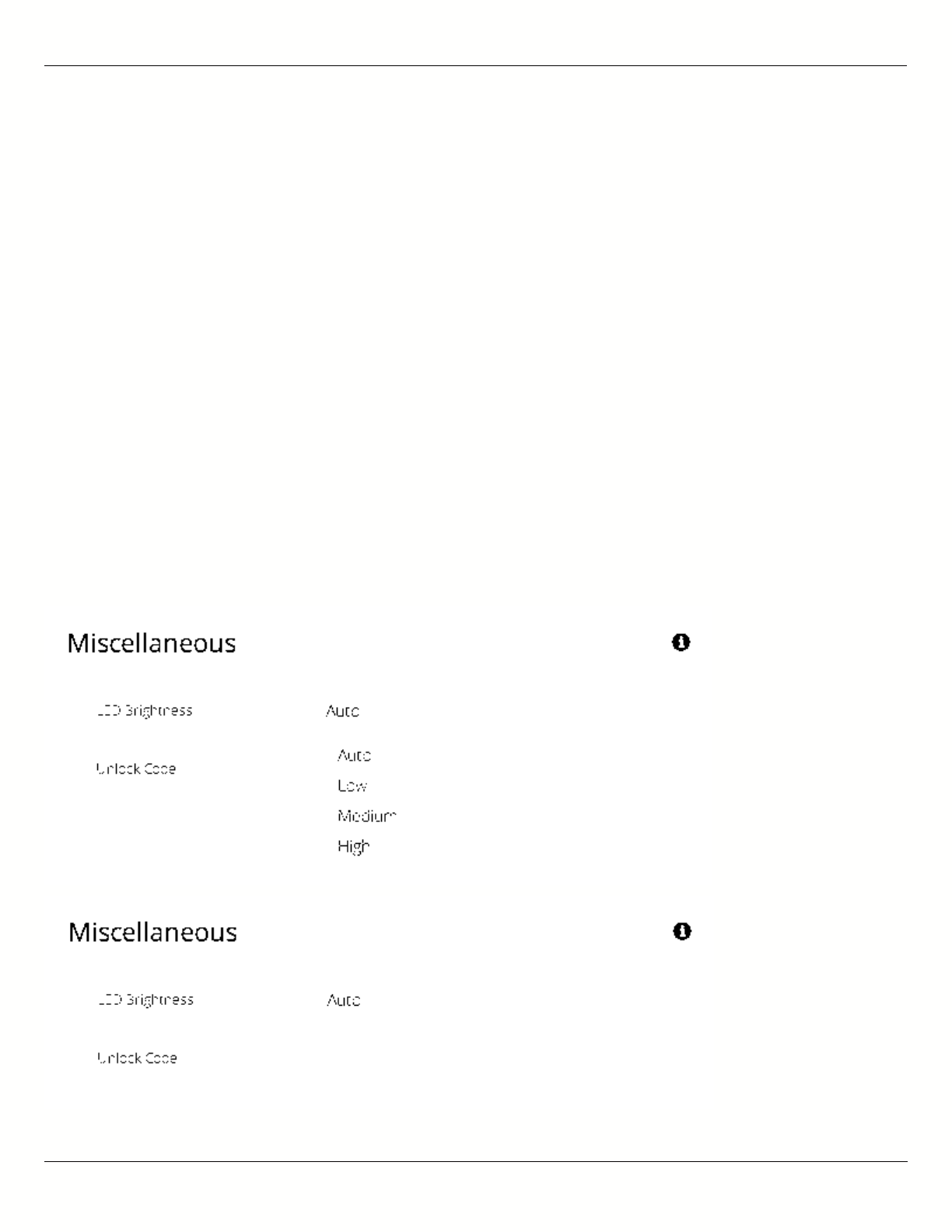
B11 User Guide
Mimosa Networks Help Site General
Copyright © 2015 Mimosa Page 38
General Miscellaneous Settings
The Miscellaneous panel contains general functionality not described elsewhere.
B5/B5c
LED Brightness - Changes the intensity of the status indicator lights on the device exterior. The Auto option
●
adjusts the amount of light based upon ambient conditions. Manual options include Low, Medium, and High.
Unlock Code - Displays the code used to unlock the device.
●
B5-Lite
Unlock Code - Displays the code used to unlock the device.
●
B11
LED Brightness - Changes the intensity of the status indicator lights on the device exterior. The Auto option
●
adjusts the amount of light based upon ambient conditions. Manual options include Low, Medium, and High.
Unlock Code - Displays the code used to unlock the device.
●

B11 User Guide
Mimosa Networks Help Site General
Copyright © 2015 Mimosa Page 39
Related:
Change Unlock Country - Replace an existing unlock code to enable another regulatory domain
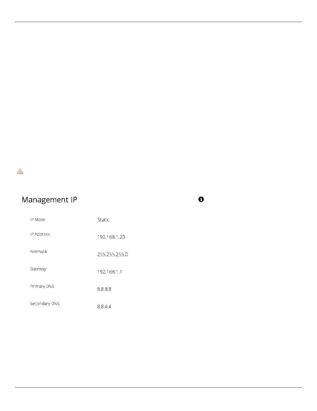
B11 User Guide
Mimosa Networks Help Site Management
Copyright © 2015 Mimosa Page 40
Setting the Management IP Address
The Management IP panel contains controls for setting the device's network address, subnet, gateway and DNS
servers.
IP Mode - Select the preferred mode of network addressing: Static or DHCP+Static Failover. If Static is chosen,
●
the device will always use the IP address that has been assigned. If DHCP+Static Failover is chosen, and a
DHCP server is available, then the addresses are automatically assigned by the DHCP server. If a DHCP server is
unavailable, the device will use the static IP address listed below.
IP Address - The network address used to manage the device.
●
Netmask - The subnet mask that defines the network subnet.
●
Gateway - The gateway address for the subnet.
●
Primary DNS - The first DNS server IP Address. Default is 8.8.8.8.
●
Secondary DNS - The backup DNS server IP Address. Default is 8.8.4.4.
●
Note that the wired Ethernet interface is configured by default to use DHCP with a static failover to the IP
Note that the wired Ethernet interface is configured by default to use DHCP with a static failover to the IP
address in the table below.
address in the table below.

B11 User Guide
Mimosa Networks Help Site Management
Copyright © 2015 Mimosa Page 41
Enabling Watchdog
The Watchdog panel contains controls to monitor a remote host and reboot the local device under configurable
failure conditions.
IP Ping Watchdog - Enables the IP Ping Watchdog feature, which resets the device if it cannot ping a certain IP
●
after a number of retry attempts.
Ping IP Address - Enter the IP address of the device to ping.
●
Interval - Set the number of seconds (1-3600) between ping attempts.
●
Delay After Startup - Set the delay in number of seconds (1-3600) between device start up and the first ping
●
attempt.
Failure Count Triggering Reboot - Set the number of failed ping attempts (1-100) before rebooting the device.
●
WARNING: rebooting will take the device offline.
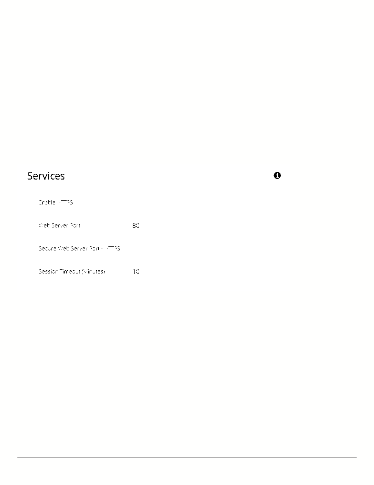
B11 User Guide
Mimosa Networks Help Site Management
Copyright © 2015 Mimosa Page 42
Management Services
The Services panel holds controls to secure management traffic by specifying how it should be served over the
network.
Enable HTTPS - Use SSL to access the web interface of this device.
●
Web Server Port - Indicate which TCP port will be used for the web server. This web server is for the web
●
interface.
Secure Web Server Port - Indicate which TCP port will be used for the secure web server.
●
Session Timeout - Set the number of minutes (0-60) of inactivity that will be allowed on the interface before
●
automatic log-out for sessions. If set to "0", the session will have no timeout.
Following an automatic session timeout, logging back into the device will take you to the Dashboard
Following an automatic session timeout, logging back into the device will take you to the Dashboard
screen.
screen.

B11 User Guide
Mimosa Networks Help Site Management
Copyright © 2015 Mimosa Page 43
Management Miscellaneous Settings
The Miscellaneous panel contains controls to enable Mimosa Cloud Management and to select the Ethernet Port data
rate, either automatically or manually.
B5/B5c
Mimosa Cloud Management - Enables the device to use Mimosa Cloud Management tools. Data will be collected
●
and stored the Mimosa Cloud.
Ethernet Port - Set the Ethernet port transfer rate or allow it to be automatically determined. Manually
●
selectable options are 10, 100, or 1000BaseT at either full or half duplex. Note that Auto or 1000BaseT/Full is
recommended so that the Ethernet port does not create a bottleneck.
Rapid Port Shutdown (RPS) - Enabling this option disables the logical link of the Ethernet port for 2 seconds
●
once every 5 minutes if the wireless link disassociates. This function becomes active only after initial
association, and repeats the off/on cycle until the link re-associates. This speeds convergence of routing and
switching protocols used in the network.
Flow Control - Enables PAUSE frames (part of 802.3x standard) to manage the transmission rate between
●
upstream senders and the Ethernet Interface.
B5-Lite
Mimosa Cloud Management - Enables the device to use Mimosa Cloud Management tools. Data will be collected
●
and stored the Mimosa Cloud.
Ethernet Port - Set the Ethernet port transfer rate or allow it to be automatically determined. Manually
●
selectable options are 10, 100, or 1000BaseT at either full or half duplex. Note that Auto or 1000BaseT/Full is
recommended so that the Ethernet port does not create a bottleneck.
Rapid Port Shutdown (RPS) - Enabling this option disables the logical link of the Ethernet port for 2 seconds
●
once every 5 minutes if the wireless link disassociates. This function becomes active only after initial
association, and repeats the off/on cycle until the link re-associates. This speeds convergence of routing and
switching protocols used in the network.
Flow Control - Enables PAUSE frames (part of 802.3x standard) to manage the transmission rate between
●
upstream senders and the Ethernet Interface.
B11
Mimosa Cloud Management - Enables the device to use Mimosa Cloud Management tools. Data will be collected
●
and stored the Mimosa Cloud.
Rapid Port Shutdown (RPS) - Enabling this option disables the logical link of the Ethernet port for 2 seconds
●
once every 5 minutes if the wireless link disassociates. This function becomes active only after initial
association, and repeats the off/on cycle until the link re-associates. This speeds convergence of routing and
switching protocols used in the network.
Flow Control - Enables PAUSE frames (part of 802.3x standard) to manage the transmission rate between
●
upstream senders and the Ethernet Interface.
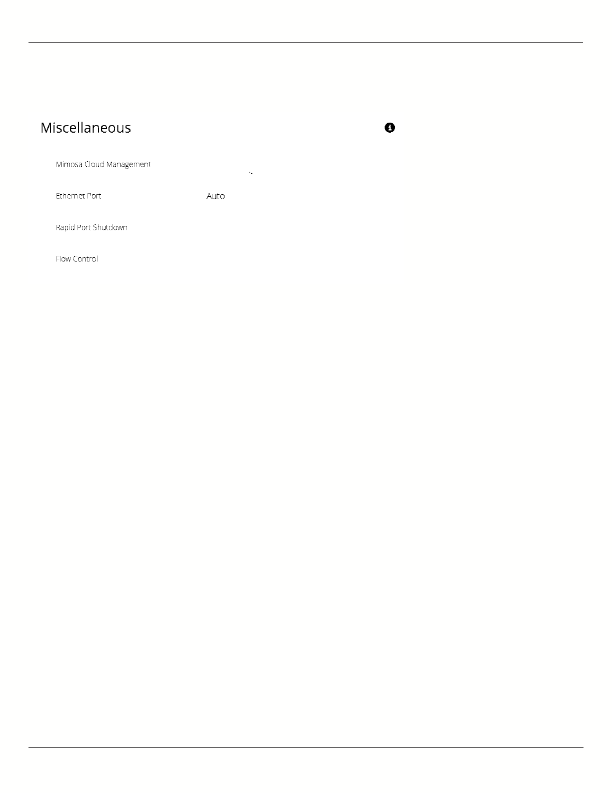
B11 User Guide
Mimosa Networks Help Site Management
Copyright © 2015 Mimosa Page 44
Note: Your firewall must be configured for outbound access to enable Mimosa Cloud Management.
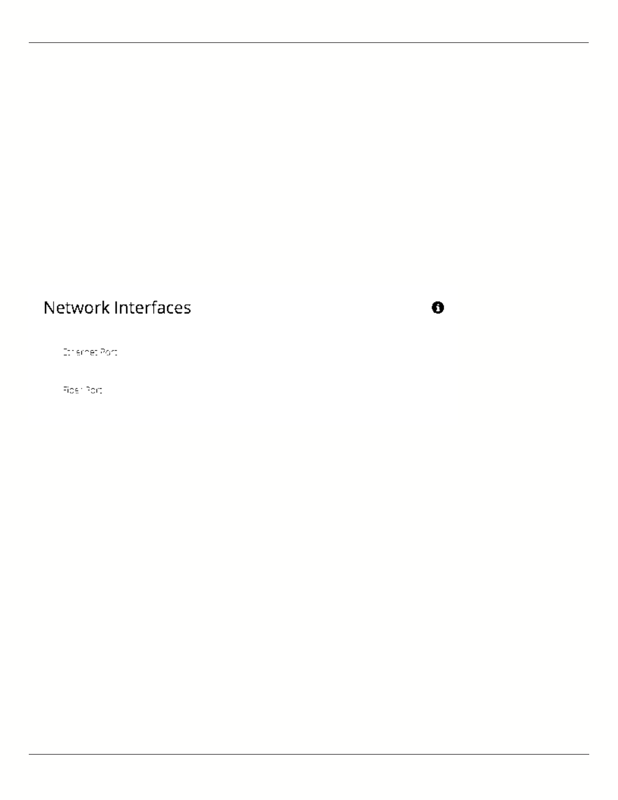
B11 User Guide
Mimosa Networks Help Site Management
Copyright © 2015 Mimosa Page 45
Network Interfaces
The Network Interfaces panel contains controls for changing data port status and speed.
B11
Ethernet Port - Set the Ethernet port transfer rate or allow it to be automatically determined. Manually
●
selectable options are 10, 100, or 1000BaseT at either full or half duplex. Note that Auto or 1000BaseT/Full is
recommended so that the Ethernet port does not create a bottleneck.
Fiber Port - Enable this option to route all data through this port with optical fiber and a small form-factor
●
pluggable (SFP) media adapter. Note that when using the Fiber Port, the Ethernet cable must remain connected
to the Ethernet Port to supply power.
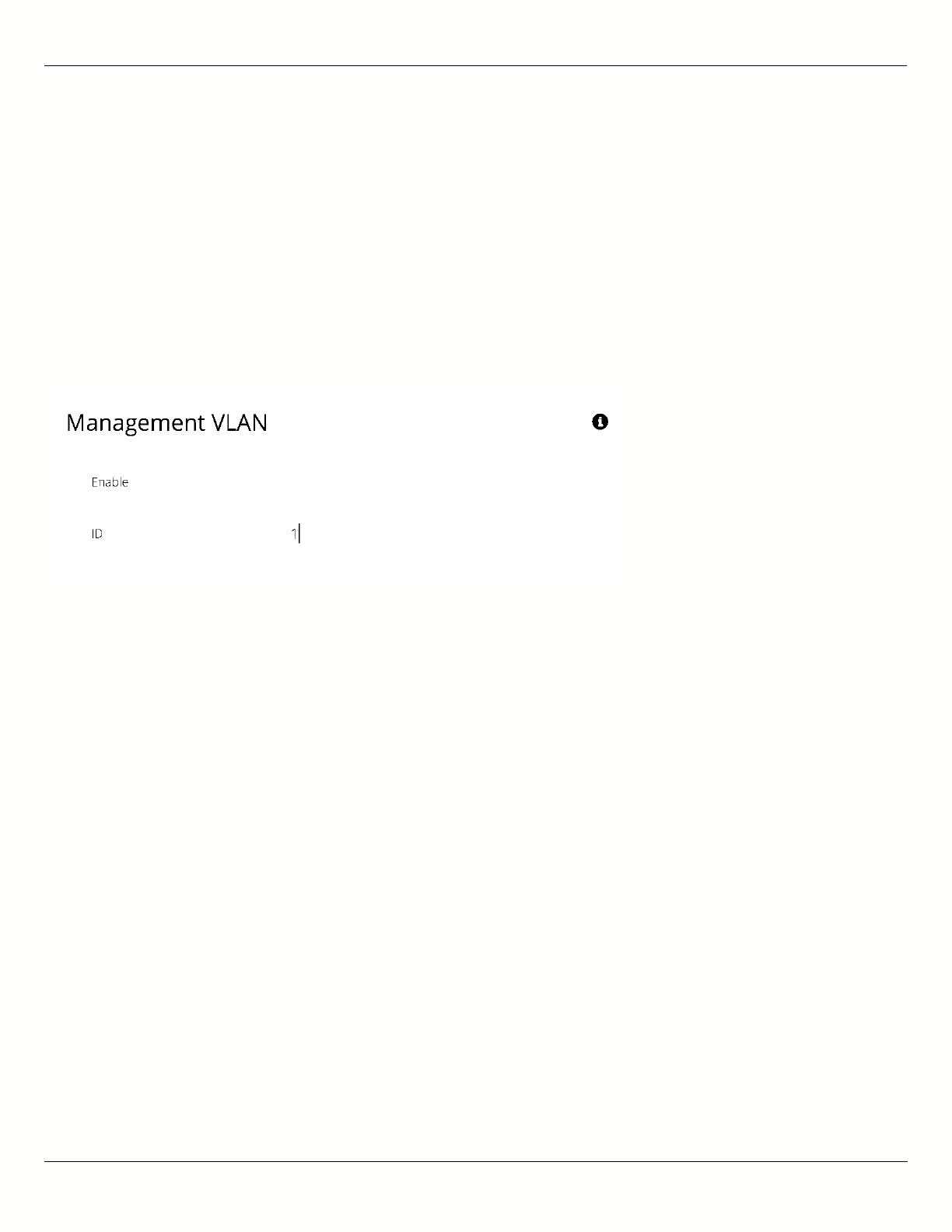
B11 User Guide
Mimosa Networks Help Site Management
Copyright © 2015 Mimosa Page 46
VLAN Management
The VLAN Management panel allows the administrator to enable a VLAN (Virtual Local Area Network) for
management traffic. When enabled, all Web Management traffic must originate from a device on that VLAN.
Enable - Use the slider control to turn VLAN Management on or off.
●
ID - The VLAN ID tag.
●
You can still connect locally via the 2.4 GHz management console on a B5 or B5c.
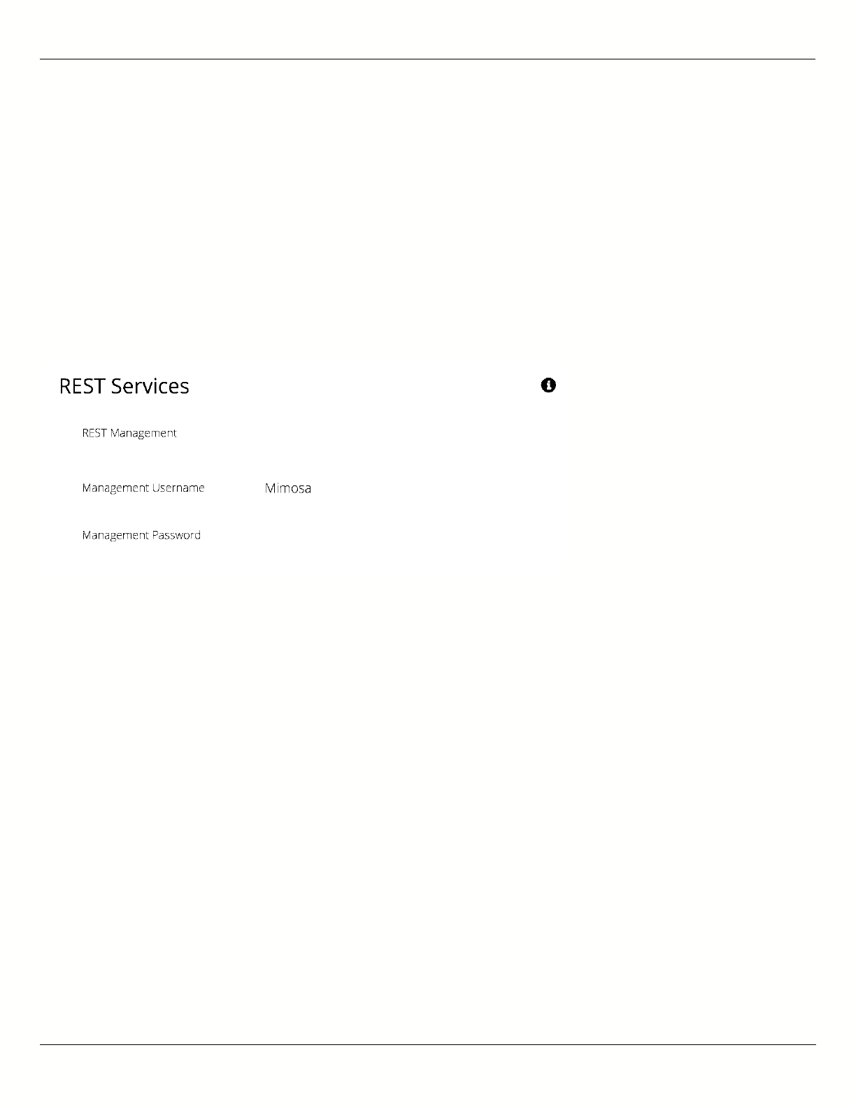
B11 User Guide
Mimosa Networks Help Site Management
Copyright © 2015 Mimosa Page 47
Configuring REST Services
The REST Services panel contains controls to enable remote access to the radio’s REST API, and then set a
username and password that will be used to log in. Note that this feature need only be activated when using a third-
party monitoring system that supports REST calls. REST services require that HTTPS is enabled.
REST Management - Use the slider control to turn REST on or off.
●
Management Username - The username that will be used to log into the local device through the REST
●
interface.
Management Password - The password that will be used to log into the local device through the REST interface.
●
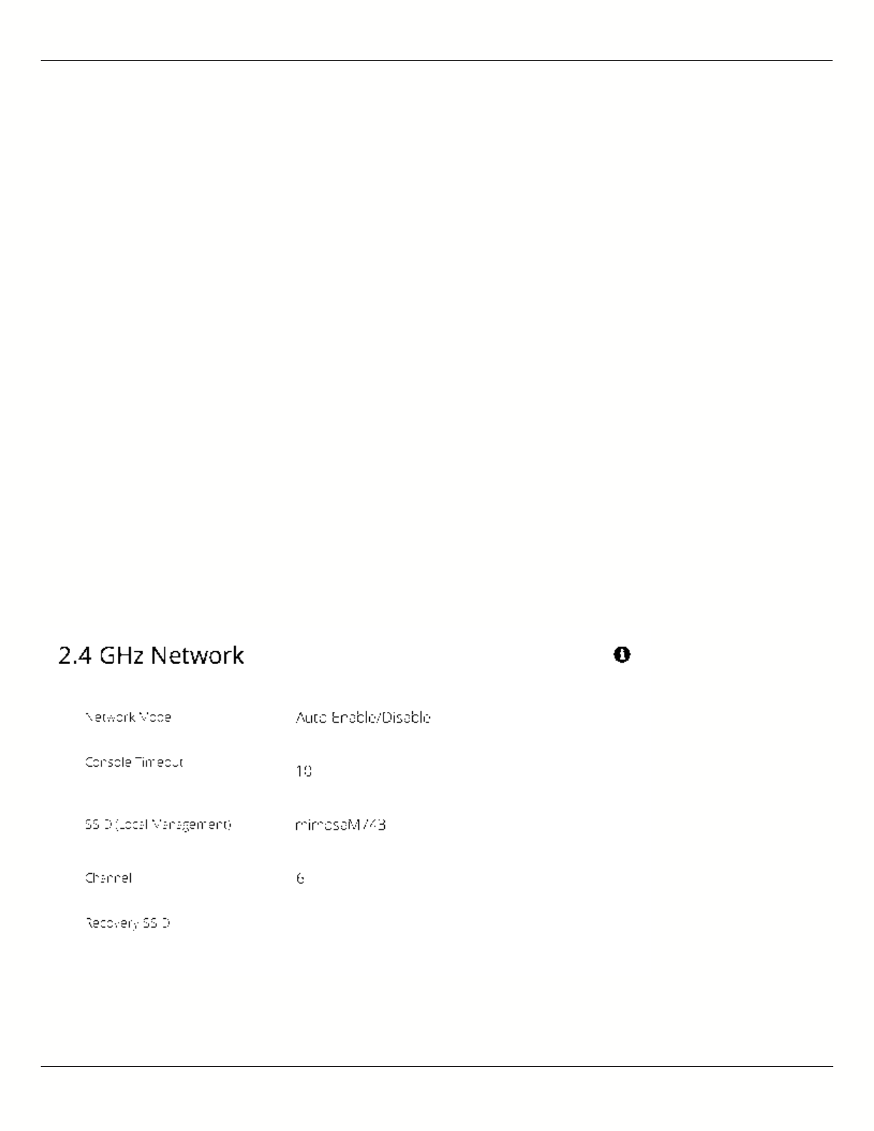
B11 User Guide
Mimosa Networks Help Site 2.4 GHz Console
Copyright © 2015 Mimosa Page 48
Enabling the 2.4 GHz Network
Product Applicability: B5/B5c, B11
The 2.4 GHz wireless interface allows local browser-based configuration with any Wi-Fi capable device. This is a low
power interface that performs best if accessed within 60 meters (~200 feet) of the radio. It is completely separate
from the link and has no performance impact on throughput if activated.
Network Mode - Choose to automatically or manually enable or disable the 2.4 GHz management network. The
●
automatic mode turns the 2.4 GHz management network on for a limited time (defined in Console Timeout)
after boot and then turns it off if there is no activity. If a user associates with the radio within the timeout
period, they will not be disconnected.
Console Timeout - Set the number of minutes (1-60) of inactivity that will be allowed on the 2.4 GHz interface
●
before the turning it off in Auto mode.
SSID (Local Management) - Set the SSID name for the 2.4 GHz local management interface.
●
Channel - Select the channel on which the 2.4 GHz wireless network will operate.
●
Recovery SSID - This is an non-editable recovery SSID that allows the device to be reset to factory defaults. This
●
is available for 5 minutes after device boot. Disabling the 2.4 GHz management network will not impact
availability of this option. The serial number of the device must be known in order to perform the factory reset.
Note: If you turn off the 2.4 GHz management radio, you can still access the device through the wired LAN interface,
or in-band through the 5 GHz wireless link. During the B5/B5c device reset process, the 2.4 GHz wireless interface is
briefly re-enabled, and then disabled after a timeout.
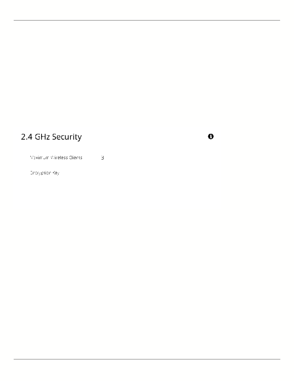
B11 User Guide
Mimosa Networks Help Site 2.4 GHz Console
Copyright © 2015 Mimosa Page 49
Setting 2.4 GHz Network Security
Product Applicability: B5/B5c, B11
The 2.4 GHz Security panel contains controls for managing access to the local wireless management network.
Maximum Wireless Clients - Limit the maximum number of wireless clients that can simultaneously access the
●
2.4 GHz management interface.
Encryption Key - Enter an ASCII Passphrase for gaining access to the 2.4 GHz management interface.
●
Show Key (checkbox) - Check to display the Encryption Key in clear text for verification before saving the
●
change.
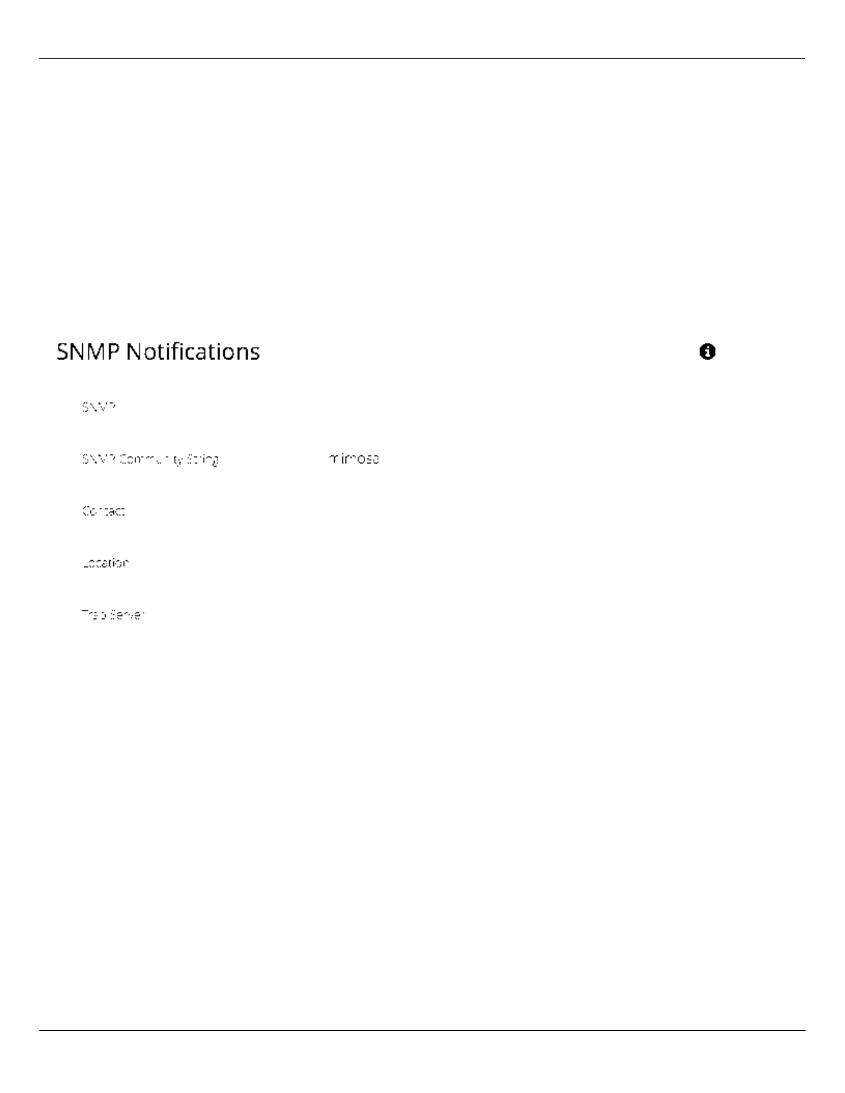
B11 User Guide
Mimosa Networks Help Site Notifications
Copyright © 2015 Mimosa Page 50
Enabling SNMP Notifications
Enable the SNMP service to allow SNMP requests and enable push notifications to a remote server.
SNMP - Enable or disable SNMP service on the local device.
●
SNMP Community String - Enter a string for use during client authentication.
●
Contact - Specify an (optional) administrative contact for the SNMP system.
●
Location - Specify the (optional) physical location for the SNMP system.
●
Trap Server - Define the server to receive the notifications.
●
Related:
SNMP Usage Examples: Get / Walk / Table - Sample commands for retrieving values
SNMP Object Names - Query values using SNMP Object Names defined within the Mimosa MIB file
SNMP Traps - Configure outgoing notifications for specific events
SNMP MIB Download - Available values in standard Management Information Base (MIB) format
SNMP OID Reference - Summarized list of available values and where to find them on the GUI
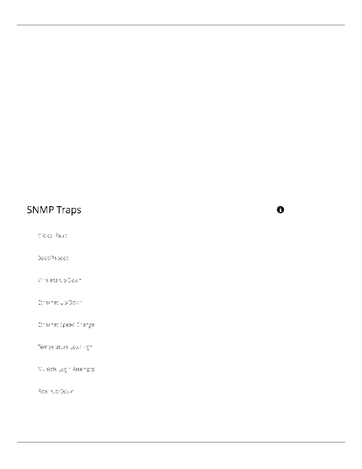
B11 User Guide
Mimosa Networks Help Site Notifications
Copyright © 2015 Mimosa Page 51
Configuring SNMP Traps
Define which traps (or notifications) are sent to the remote SNMP server.
Critical Fault - Notification created if the device is forced to reboot.
●
Boot/Reboot - Notification created if the system boots or reboots.
●
Wireless Up/Down - Notification created if the device connects to (Wireless Up) or disconnects from (Wireless
●
Down) another device.
Ethernet Up/Down - Notification created if the Ethernet Port is connected (Ethernet Up) or disconnected
●
(Ethernet Down).
Ethernet Speed Change - Notification created when the Ethernet port changes from one speed (10, 100, or
●
1000BaseT) to another.
Temperature Low/High - Notification created if the temperature falls outside of the safe range for the product.
●
Multiple Login Attempts - Notification created if multiple failed login attempts are made from the same IP
●
Address.
Fiber Up/Down (B11) - Notification created when the SFP port is connected (Fiber) or disconnected (Down).
●

B11 User Guide
Mimosa Networks Help Site Notifications
Copyright © 2015 Mimosa Page 52
Related:
SNMP Usage Examples: Get / Walk / Table - Sample commands for retrieving values
SNMP Object Names - Query values using SNMP Object Names defined within the Mimosa MIB file
SNMP Notifications - Enabling SNMP on Mimosa Backhaul products
SNMP MIB Download - Available values in standard Management Information Base (MIB) format
SNMP OID Reference - Summarized list of available values and where to find them on the GUI
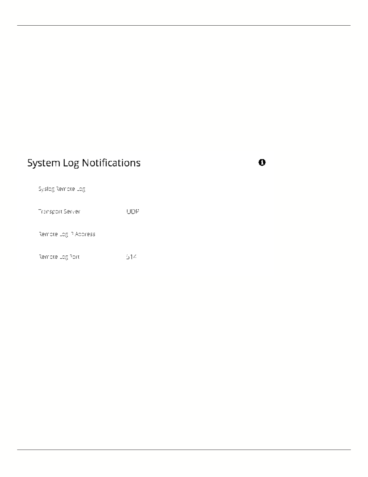
B11 User Guide
Mimosa Networks Help Site Notifications
Copyright © 2015 Mimosa Page 53
Enabling System Log Notifications
Enable Syslog service on the local device to send traps to a remote Syslog server.
Syslog Remote Log - Enable or disable Syslog service on the local device.
●
Transport Server - Choose the desired protocol for the Syslog connection. Note that most devices send UDP
●
messages by default. UDP is an unreliable transmission protocol, thus messages may get lost. Choose TCP for
higher reliability if any message loss is unacceptable.
Remote Log IP Address - List the IP Address of the remote Syslog server to which Notifications will be sent.
●
Remote Log Port - List the Port on the remote Syslog server to which Notifications will be sent.
●
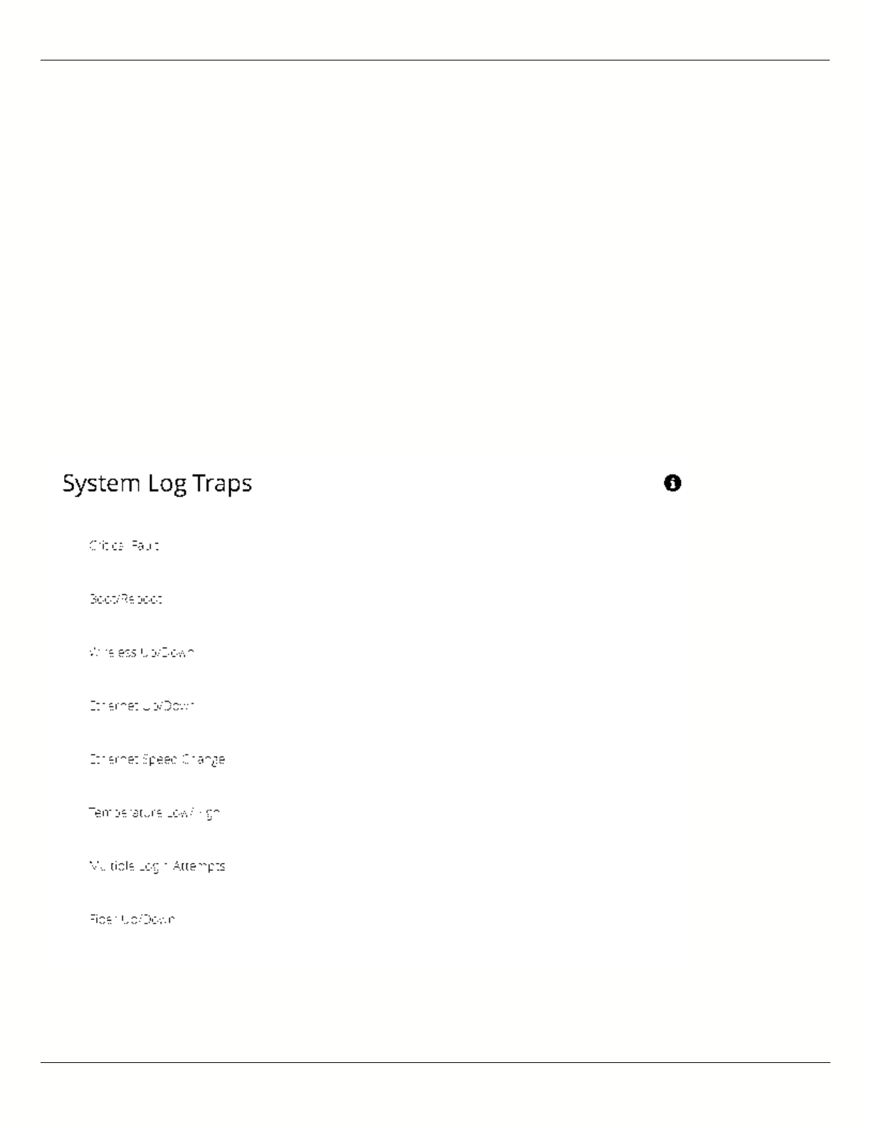
B11 User Guide
Mimosa Networks Help Site Notifications
Copyright © 2015 Mimosa Page 54
Configuring System Log Traps
Define which traps (or notifications) are sent to the remote server for the System Log.
Critical Fault - Notification created if the device is forced to reboot.
●
Boot/Reboot - Notification created if the system boots or reboots.
●
Wireless Up/Down - Notification created if the device connects to (Wireless Up) or disconnects from (Wireless
●
Down) another device.
Ethernet Up/Down - Notification created if the Ethernet Port is connected (Ethernet Up) or disconnected
●
(Ethernet Down).
Ethernet Speed Change - Notification created when the Ethernet port changes from one speed (10, 100, or
●
1000 BaseT) to another.
Temperature Low/High - Notification created if the temperature falls outside of the safe range for the product.
●
Multiple Login Attempts - Notification created if multiple login attempts are made from the same IP Address.
●
Fiber Up/Down (B11) - Notification created when the Fiber port is connected (Fiber) or disconnected (Down).
●
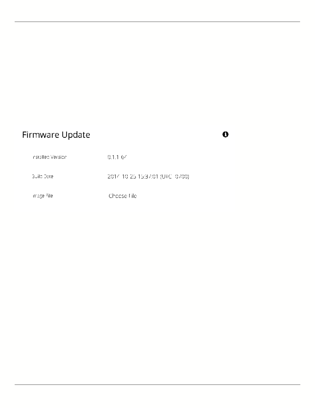
B11 User Guide
Mimosa Networks Help Site Firmware & Reset
Copyright © 2015 Mimosa Page 55
Performing a Firmware Update
The Firmware Update panel displays the current firmware version and date, and allows the user to upload a new
firmware image. The latest firmware image may be downloaded from help.mimosa.co. Alternately, firmware can be
pushed to the device automatically through the Manage application at manage.mimosa.co.
Installed Version - The currently installed firmware version.
●
Build Date - The date that the installed firmware was created.
●
Image File - Update to the latest firmware. Click the Choose File button to select a file for upload the file.
●
When performing a Firmware upgrade, it is advisable to reboot and then upgrade the remote side of the
When performing a Firmware upgrade, it is advisable to reboot and then upgrade the remote side of the
link before the local side. If there is a problem during the upgrade you will still have access to one of the
link before the local side. If there is a problem during the upgrade you will still have access to one of the
radios within the link and can manage the link details.
radios within the link and can manage the link details.
The firmware update process occurs in four phases:
Upload - Selecting a firmware image and uploading to the radio1.
Verification - Ensuring that the firmware image is complete and without errors2.
Upgrade - Writing the new firmware image to flash memory3.
Reboot - Restarting with the new firmware image (~90 seconds)4.
Once the remote radio enters the Upgrade phase, it is generally safe to begin the Upload phase to the local radio.
Alternately, the Mimosa Manage application offers a parallel upgrade feature which sends the firmware image to
both radios, and once both radios receive and verify the image, they upgrade at the same time and reboot in an
order that you specify.
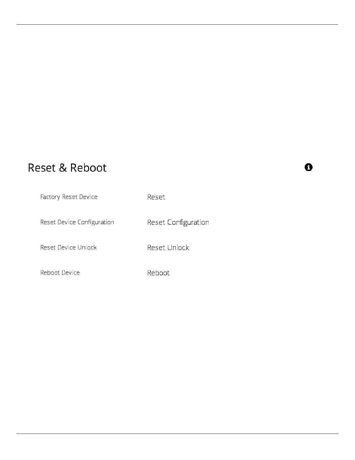
B11 User Guide
Mimosa Networks Help Site Firmware & Reset
Copyright © 2015 Mimosa Page 56
Reset & Reboot the Device
Reboot the device or reset it to its original factory settings.
Factory Reset Device - Clears all configuration settings and locks the device. WARNING: This will delete ALL
●
saved configuration settings and return the device to the locked factory state. You will be required to re-enter
your unlock key upon device reset. The current version of firmware will remain, however.
Reset Device Configuration - Clears all configuration settings. The device will remain unlocked.
●
Reset Device Unlock - Locks the device and resets the country code. WARNING: You will be required to re-enter
●
your unlock key upon reset.
Reboot Device - Restarts the device.
●
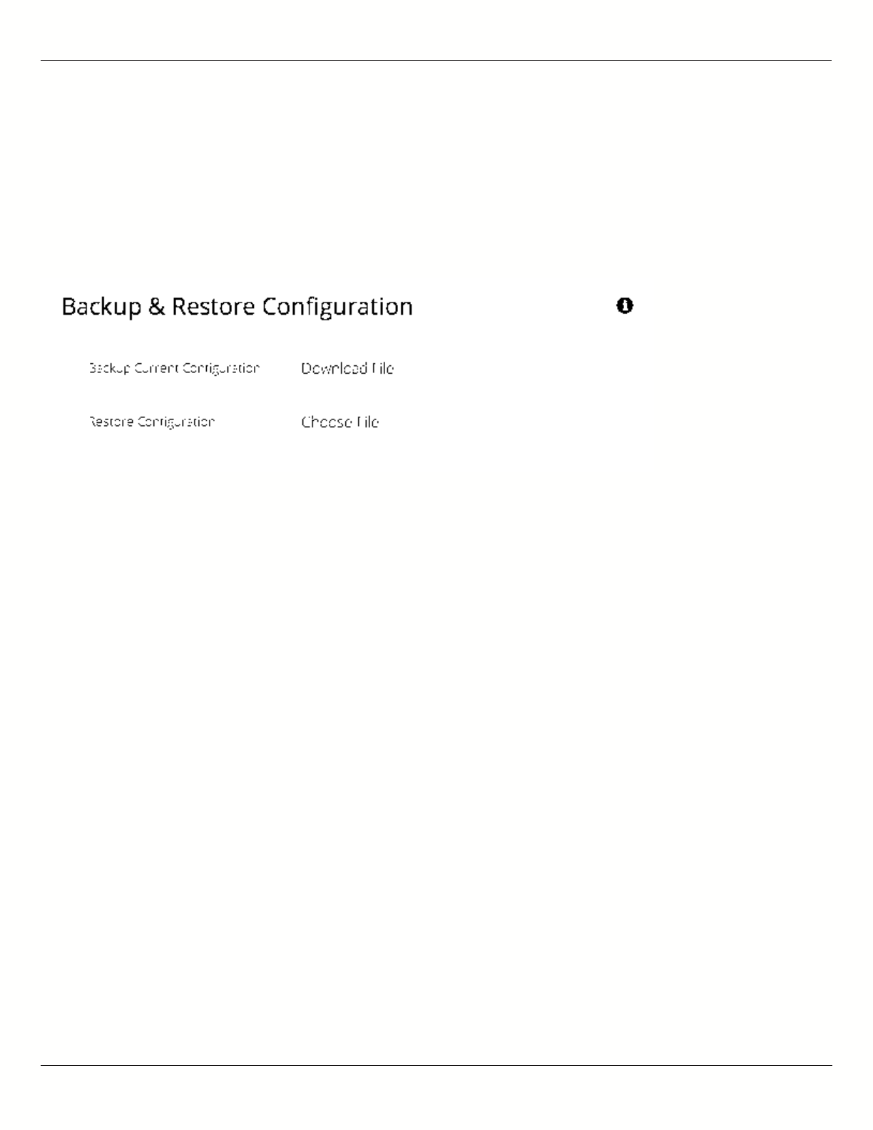
B11 User Guide
Mimosa Networks Help Site Backup & Restore
Copyright © 2015 Mimosa Page 57
Backup or Restore Configuration Settings
The Backup and Restore Configuration panel contains controls for managing configuration settings files.
Backup Current Configuration - Perform a configuration backup by downloading the mimosa.conf file.
●
Restore Configuration - Click the Choose File button to upload a previously saved mimosa.conf file.
●

B11 User Guide
Mimosa Networks Help Site Tests
Copyright © 2015 Mimosa Page 58
Diagnostic Tests
Three types of tests are available within the Diagnostics section: Ping, Bandwidth and Traceroute.
Ping Test
A low level ICMP test which indicates whether the target host is reachable from the local device.
Destination Host - The destination IP Address of the device to ping.
●
Packet Count - The number of packets to transmit during a ping.
●
Packet Size - The size of each packet to transmit during a ping.
●
Run Test - Click on the Run Test button to ping the destination IP address. Results are shown in the
●
corresponding table.
Bandwidth Test
A manual test to assess maximum throughput when minimal or no traffic is present. This test sends 1500-byte
packets using a proprietary UDP-like protocol. Results are shown in corresponding graph on this page. Note that
bandwidth test data is excluded from the Dashboard Performance graph. This is because the test is conducted by
transmitting packets at a low layer between the two radios. Navigating away from this page will stop the test. The
bandwidth test is only available when the devices are associated.
Test Duration - The length of the bandwidth test in seconds.
●
Test - Select one of the following options to assess the maximum throughput:
●
Local to Remote - Unidirectional test from the local device to the remote device
●
Remote to Local - Unidirectional test from the remote device to the local device
●
Transmit then Receive - Bidirectional tests conducted in series
●
Simultaneous - Bidirectional test conducted in parallel
●
Traceroute Test
A network utility used to display the path and transit delay between the local device and a given destination across
an IP network.
Destination Host - The destination IP address for traceroute to send packets.
●
Resolve IP Address - Indicate whether the system should resolve and print the host name of the destination.
●
Max Number of Hops - Choose the maximum number of intermediate devices (e.g. routers) through which
●
packets must pass between source and destination.
Run Test - Click on the Run Test button to begin the traceroute test. Results are shown in the corresponding
●
table.
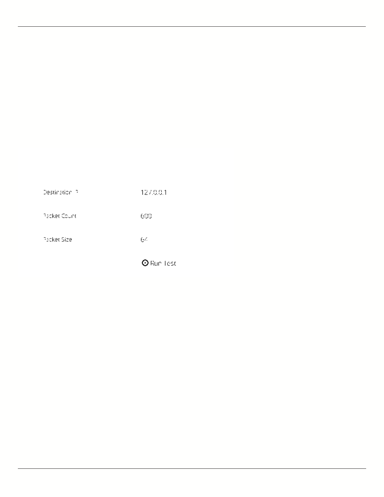
B11 User Guide
Mimosa Networks Help Site Tests
Copyright © 2015 Mimosa Page 59
Running a Ping Test
A low level ICMP test which indicates whether the target host is reachable from the local device.
Destination Host - The destination IP Address of the device to ping.
●
Packet Count - The number of packets to transmit during a ping.
●
Packet Size - The size of each packet to transmit during a ping.
●
Run Test - Click on the Run Test button to ping the destination IP address. Results are shown in corresponding
●
table.
B11 User Guide
Mimosa Networks Help Site Tests
Copyright © 2015 Mimosa Page 60
Running a Bandwidth Test
A manual test to assess maximum throughput when minimal or no traffic is present. This test sends 1500-byte
packets using a proprietary UDP-like protocol. Results are shown in corresponding graph on this page. Note that
bandwidth test data is excluded from the Dashboard Performance graph. This is because the test is conducted by
transmitting packets at a low layer between the two radios. Navigating away from this page will stop the test. The
bandwidth test is only available when devices are associated.
Test Duration - The length of the bandwidth test in seconds.
●
Test - Select one of the following options to assess the maximum throughput:
●
Local to Remote - Unidirectional test from the local device to the remote device
●
Remote to Local - Unidirectional test from the remote device to the local device
●
Transmit then Receive - Bidirectional tests conducted one after the other
●
Simultaneous - Bidirectional test conducted at the same time
●

B11 User Guide
Mimosa Networks Help Site Tests
Copyright © 2015 Mimosa Page 61
Running a Traceroute Test
A network utility used to display the path and transit delay between the local device and a given destination across
an IP network.
Destination Host - The destination IP address for traceroute to send packets.
●
Resolve IP Address - Indicate whether the system should resolve and print the host name of the destination.
●
Max Number of Hops - Choose the maximum number of intermediate devices (e.g. routers) through which
●
packets must pass between source and destination.