Minde Electronics Technology MS3590 Barcode Scanner User Manual
Shenzhen Minde Electronics Technology LTD. Barcode Scanner Users Manual
UserManual.wiki
>
Minde Electronics Technology
>
MS3590 User Manual
Users Manual
Navigation menu
Upload a User Manual
Namespaces
Wiki Guide
HTML
PDF
Info
Views
User Manual
Discussion / Help
Navigation

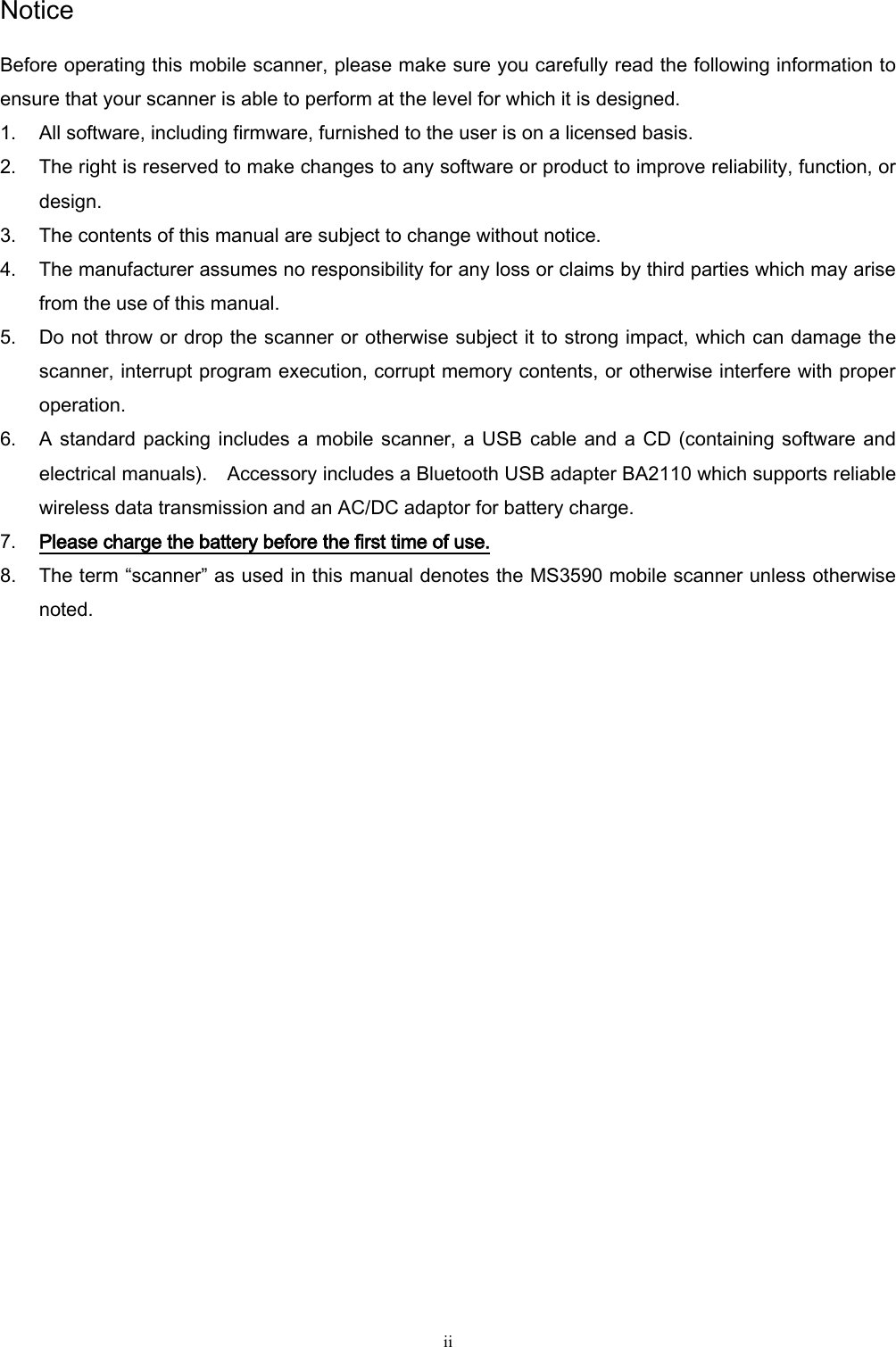
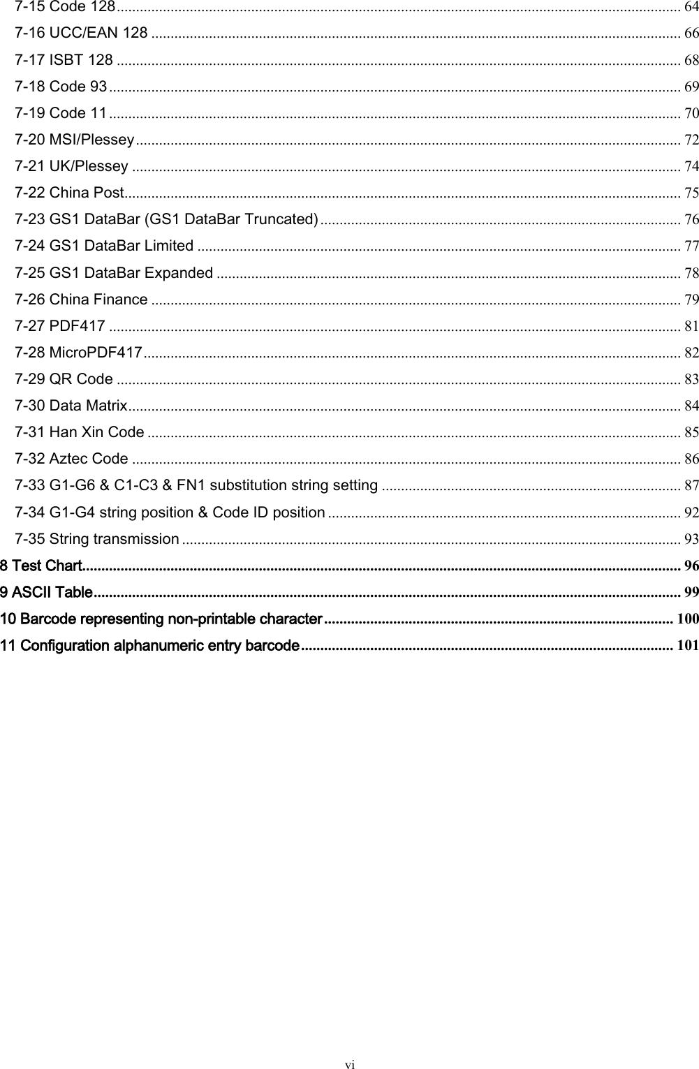
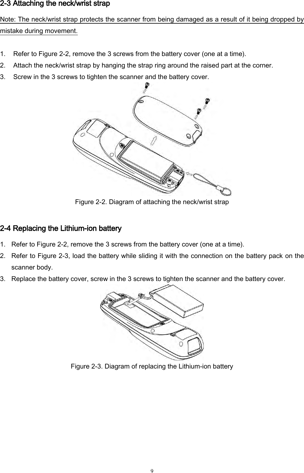
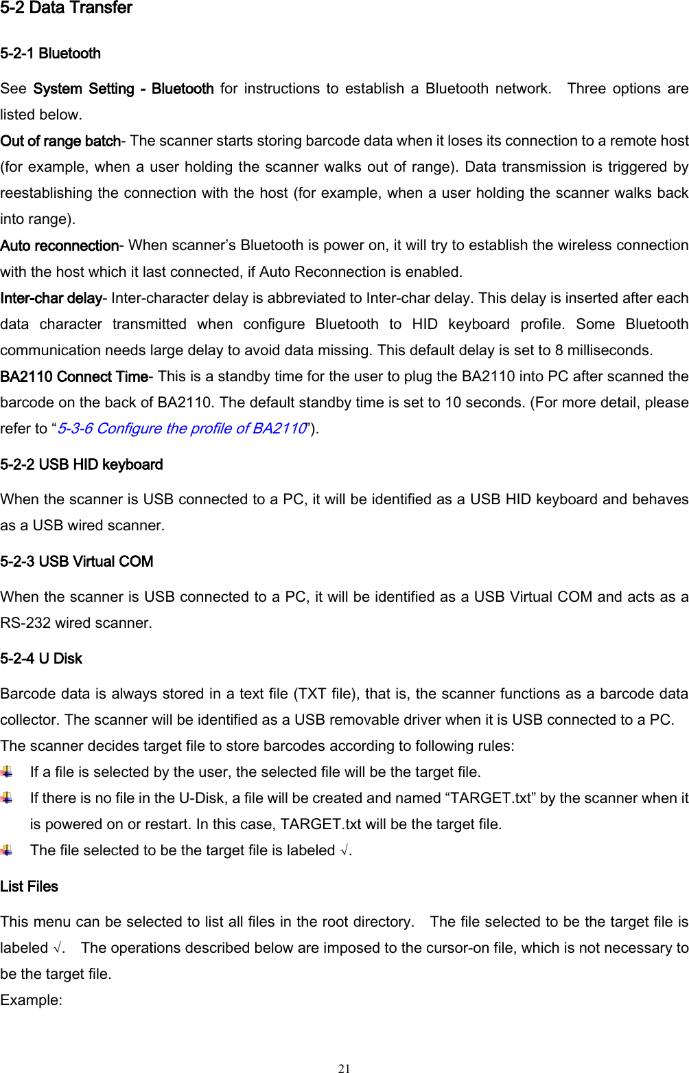
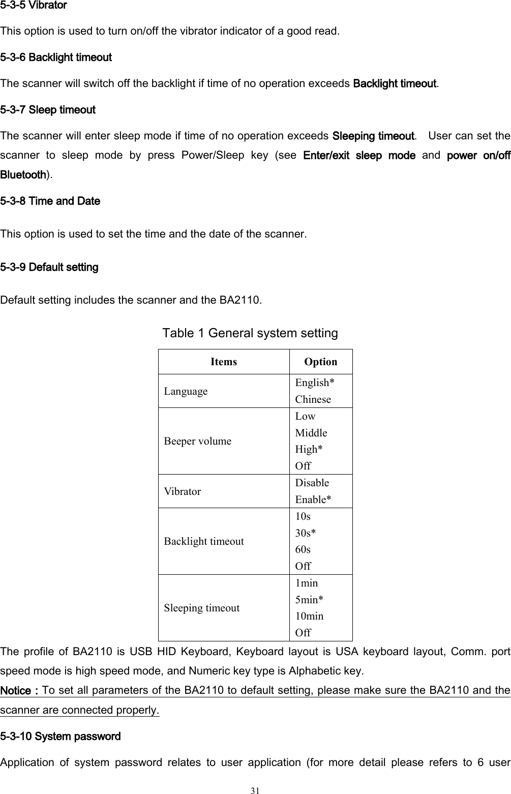
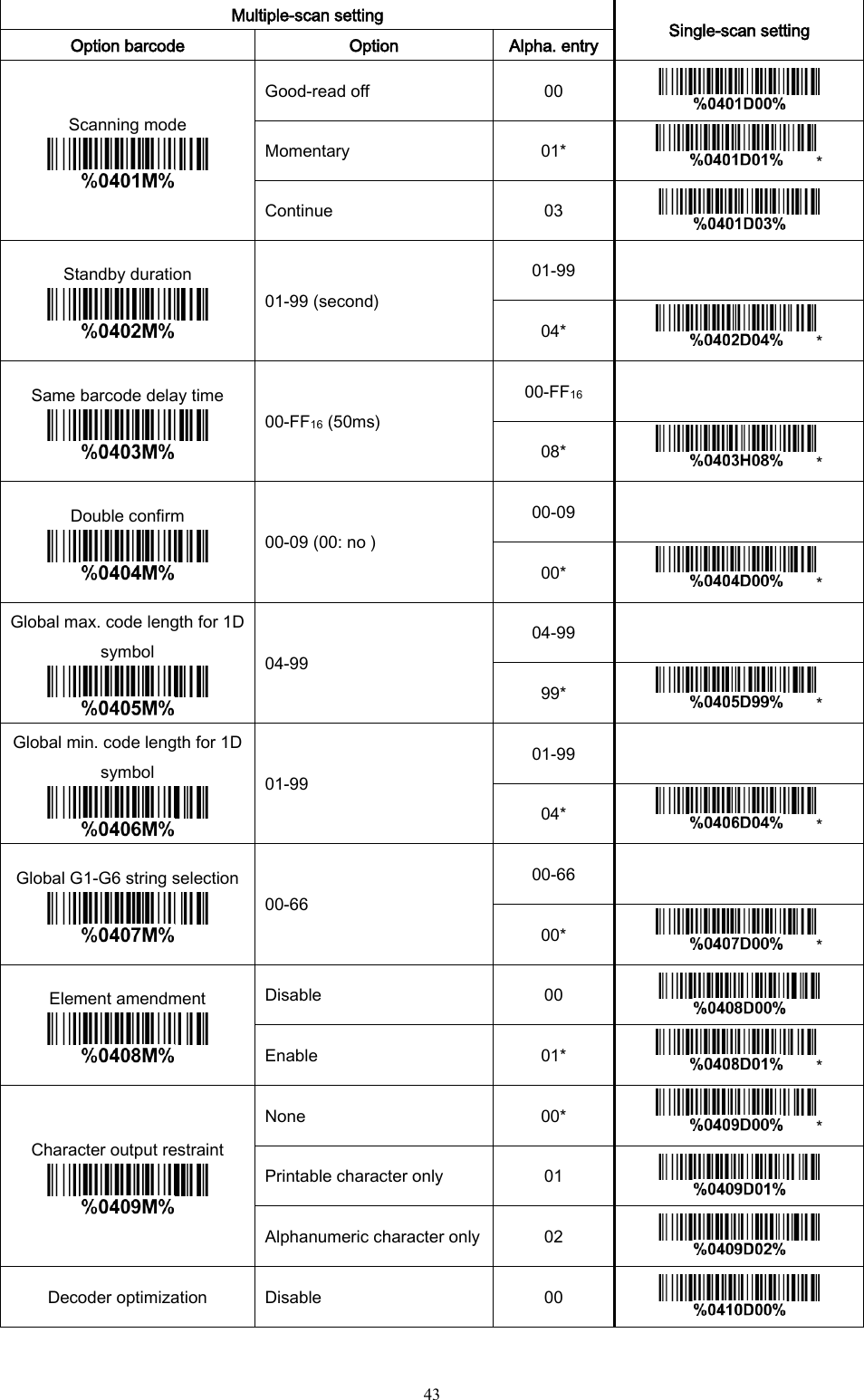
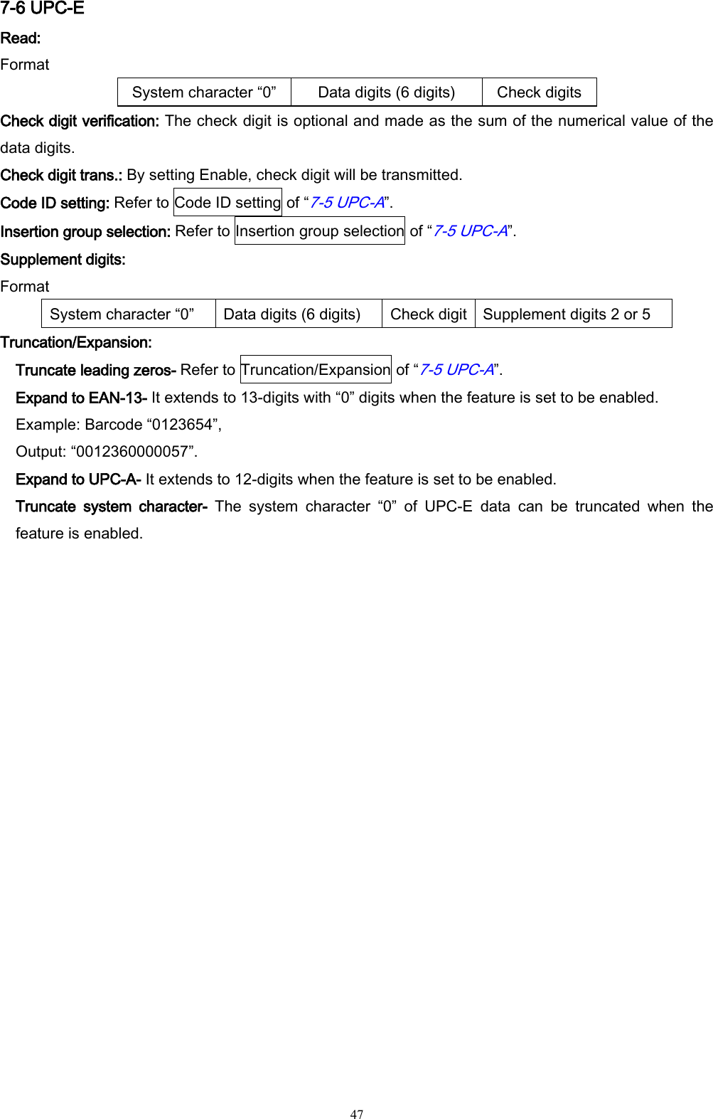
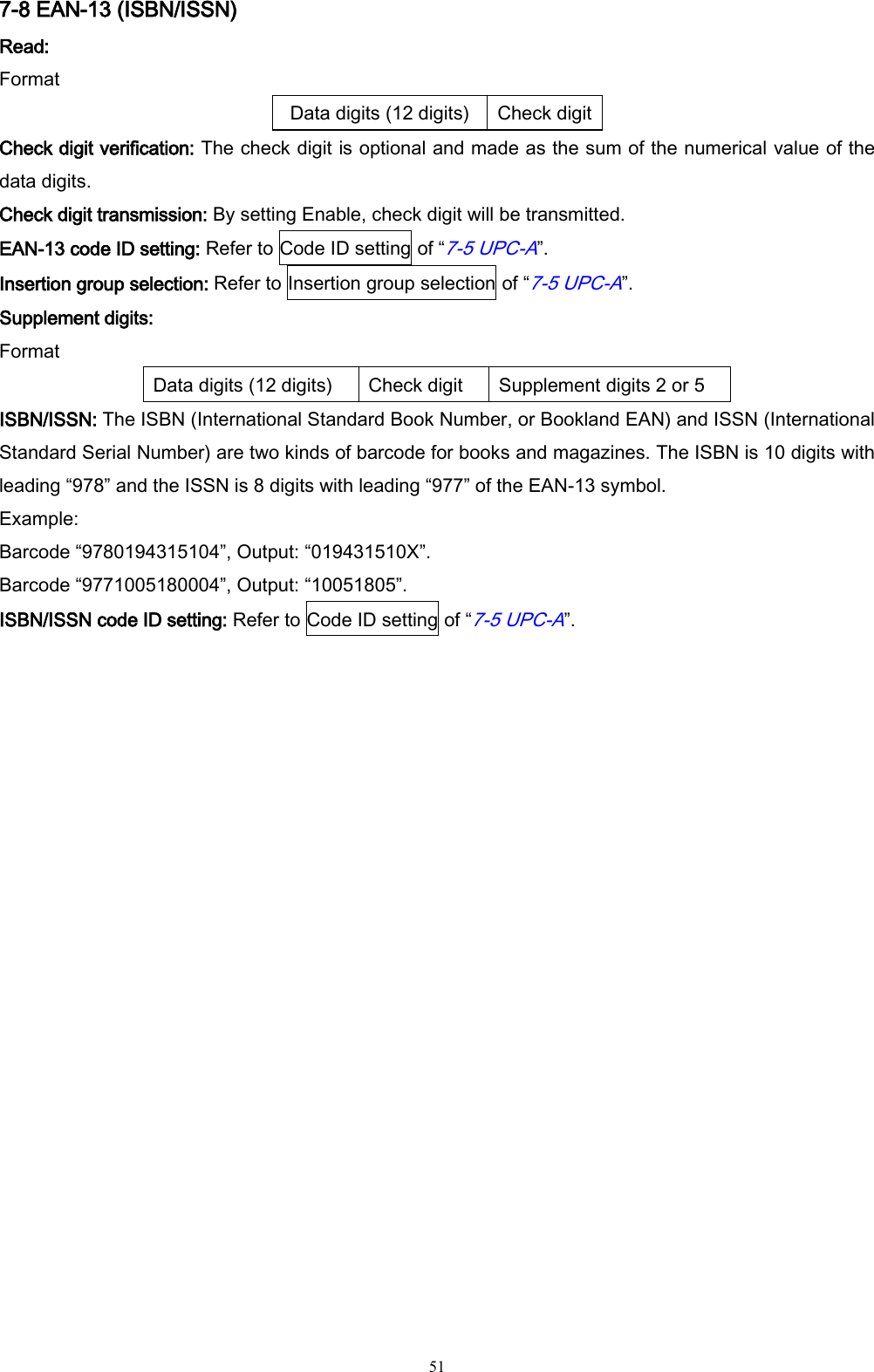
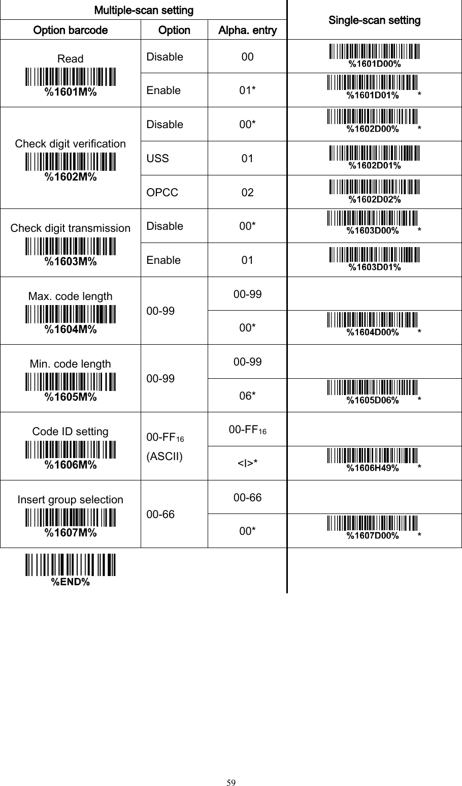
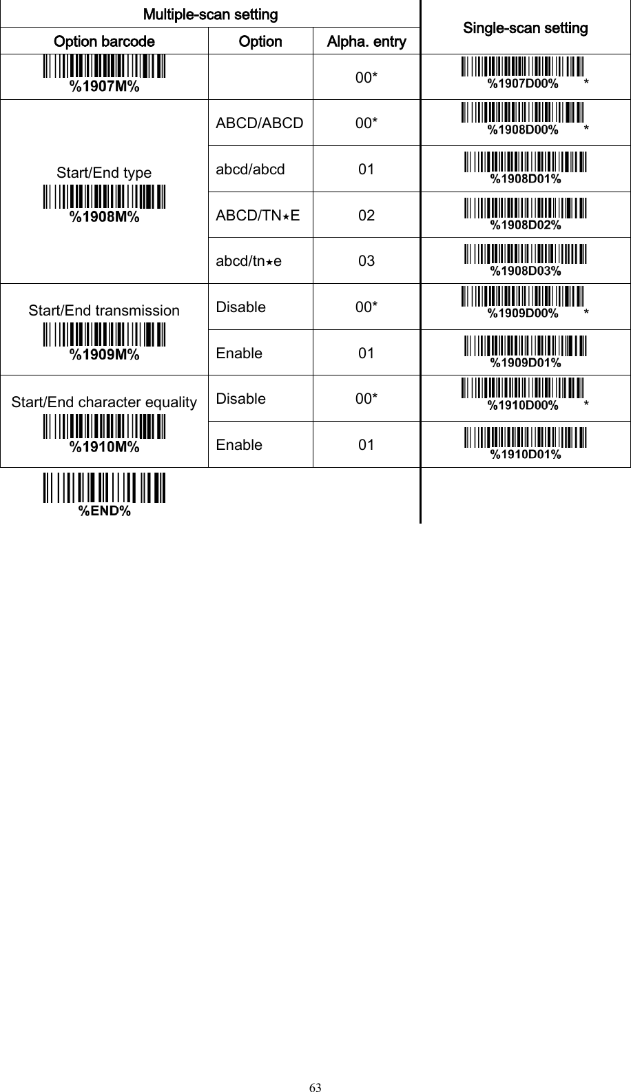
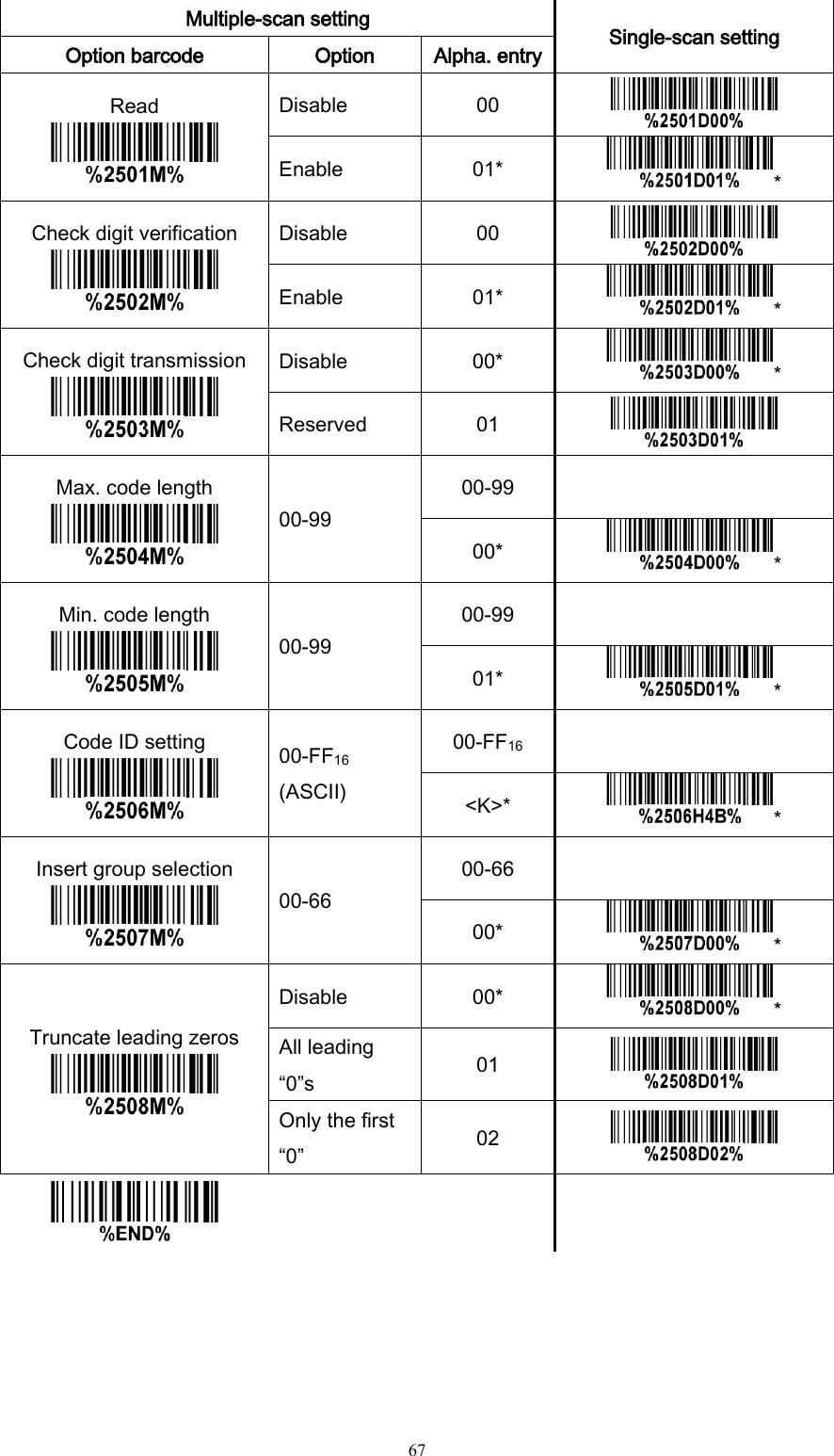
![3 1-2 Default settings for each barcode Table 1-3 Default setting for each barcode Code type Read enable Check digit verification Check digit transmission Min. code length Proprietary code ID AIM code ID UPC-A √ √ √ (12)2 A ]Em UPC-E √ √ √ (8)2 D ]Em UPC-E1 √ √ √ (8)2 D ]Em EAN-13 √ √ √ (13)2 A ]Em EAN-8 √ √ √ (8)2 C ]Em ISBN (Bookland EAN) / ISSN1 √ √ √ (13)2 B ]Em Code 39 √ - - 1 M ]Am Interleaved 2 of 5 √ - - 6 I ]Im Industrial 2 of 5 - - - 4 H ]Im Matrix 2 of 5 √ - - 6 X ]Im Codabar √ - - 4 N ]Fm Code 128 √ √ - 1 K ]Cm UCC/EAN 128 √ √ - 1 K ]Cm ISBT 128 √ √ - 1 K ]Cm Code 93 √ √ - 1 L ]Gm Code 11 - √ - 4 V - MSI/Plessey - - - 4 O ]Mm UK/Plessey - √ - 1 U ]Mm China Post √ - - (11)2 T ]Im China Finance √ - - (10)2 Y - GS1 DataBar √ - - (16)2 R ]em GS1 DataBar Truncated3 √ - - (16)2 R ]em GS1 DataBar Limited √ - - (16)2 R ]em GS1 DataBar Expanded √ - - 1 R ]em PDF417 √ - - - - -](https://usermanual.wiki/Minde-Electronics-Technology/MS3590/User-Guide-2349746-Page-10.png)
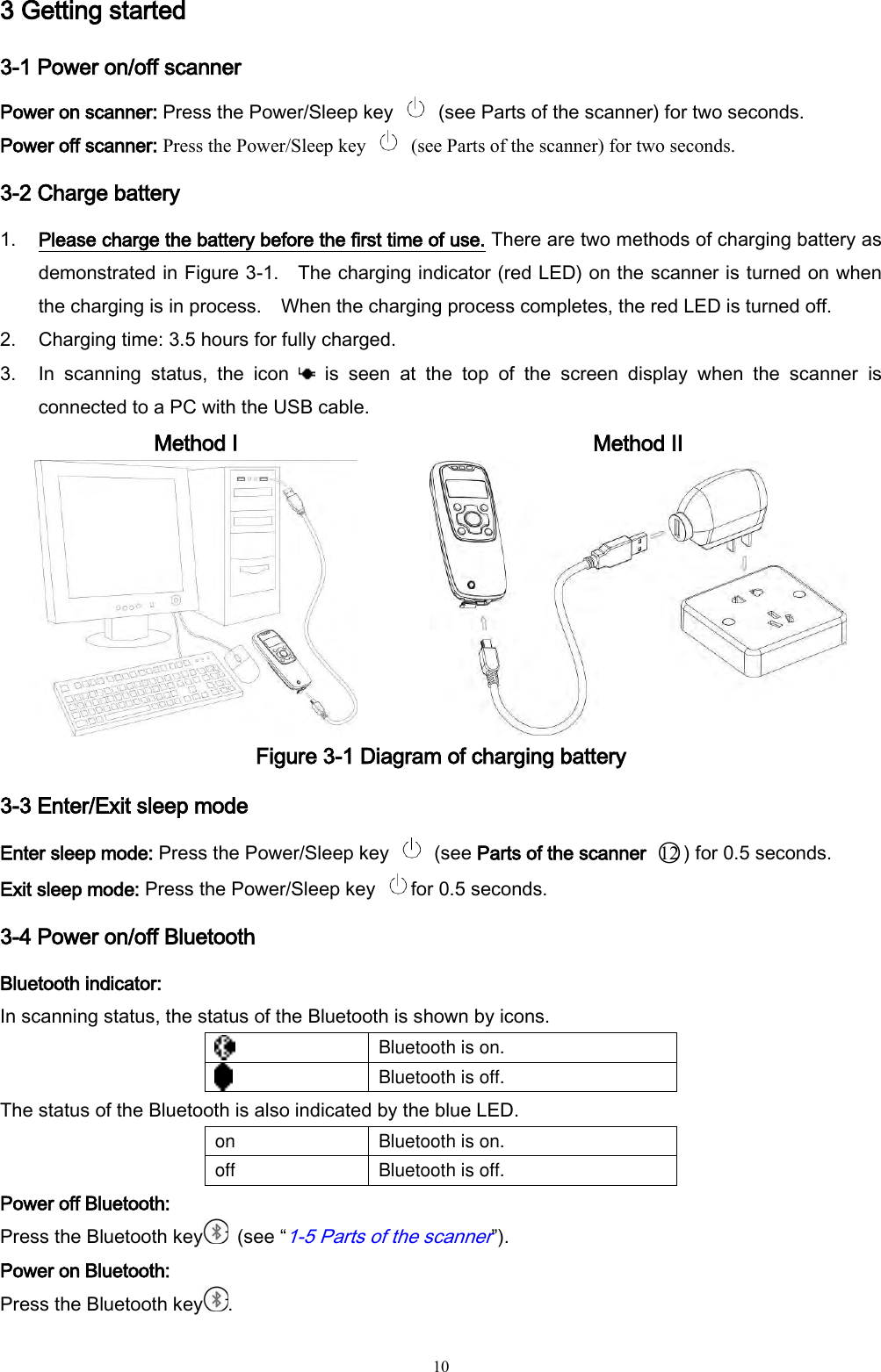
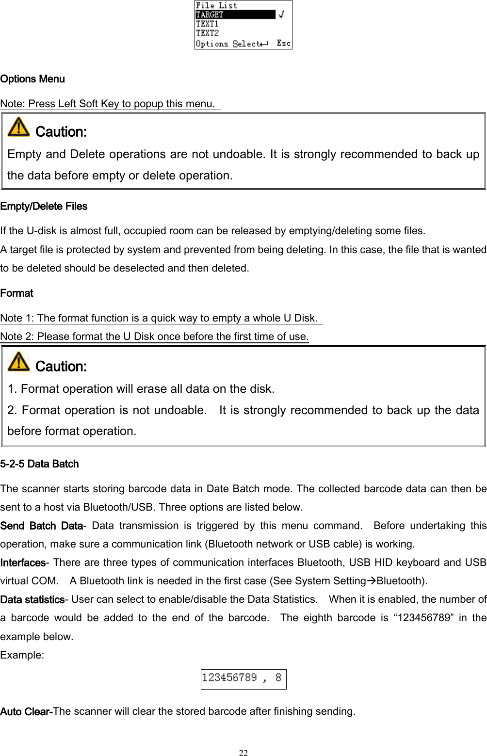
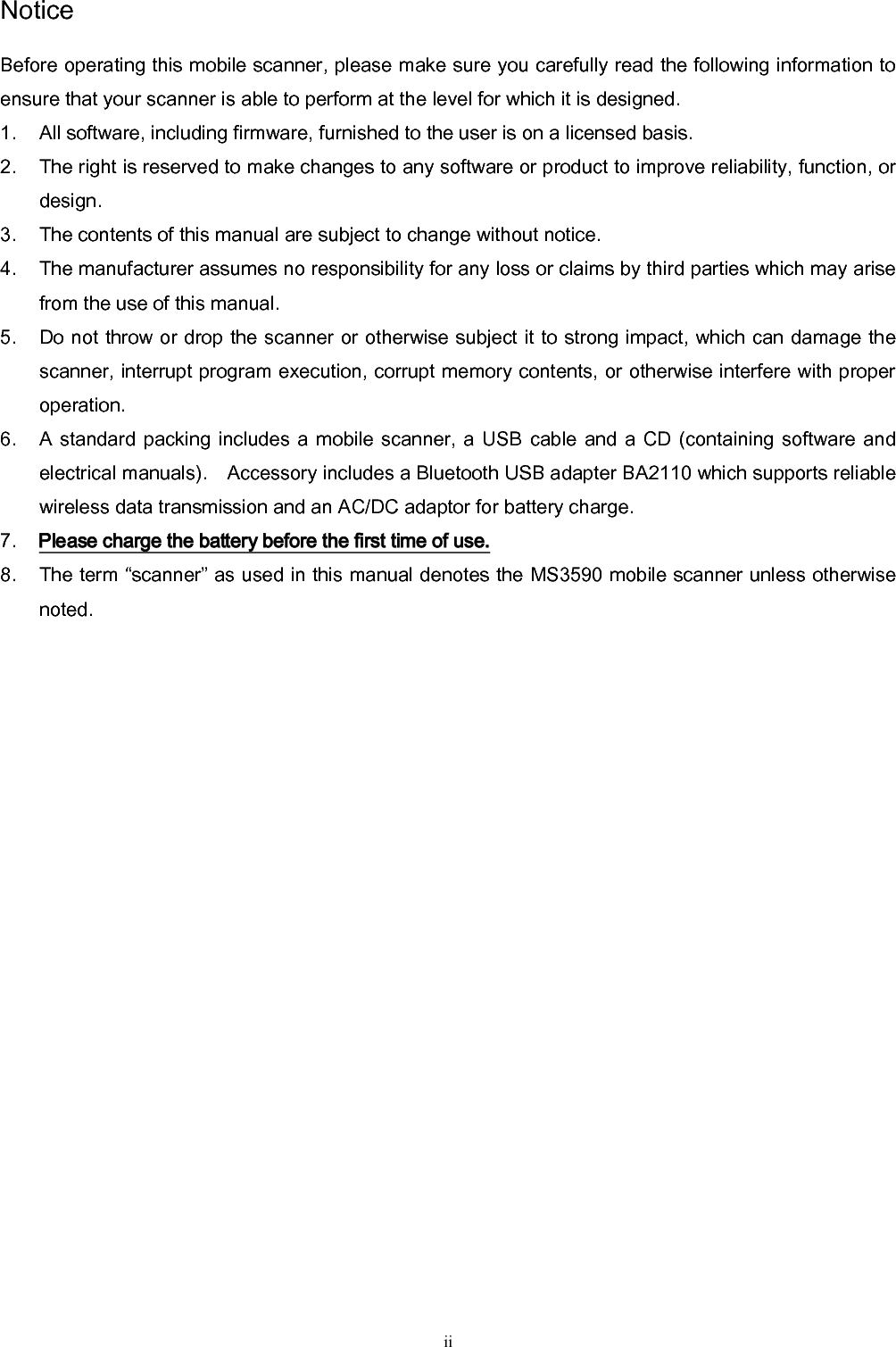
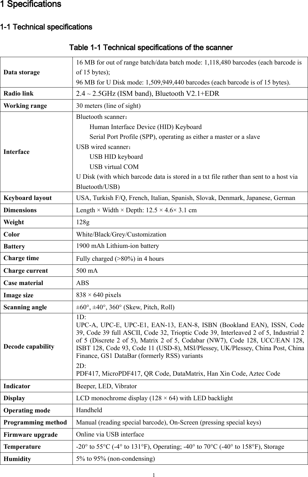
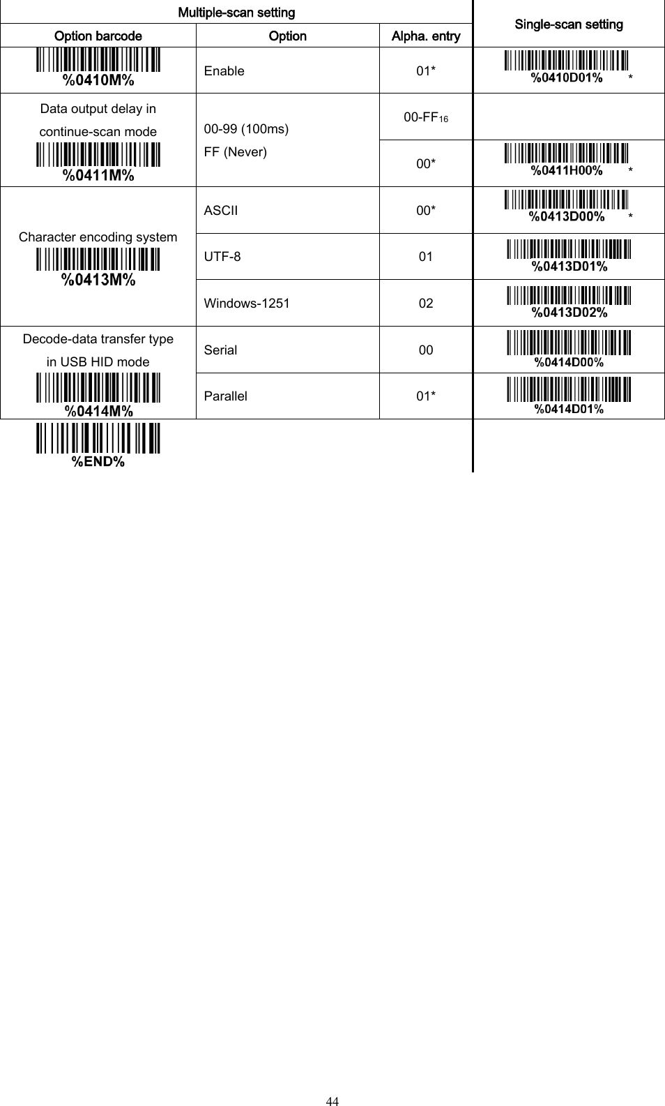
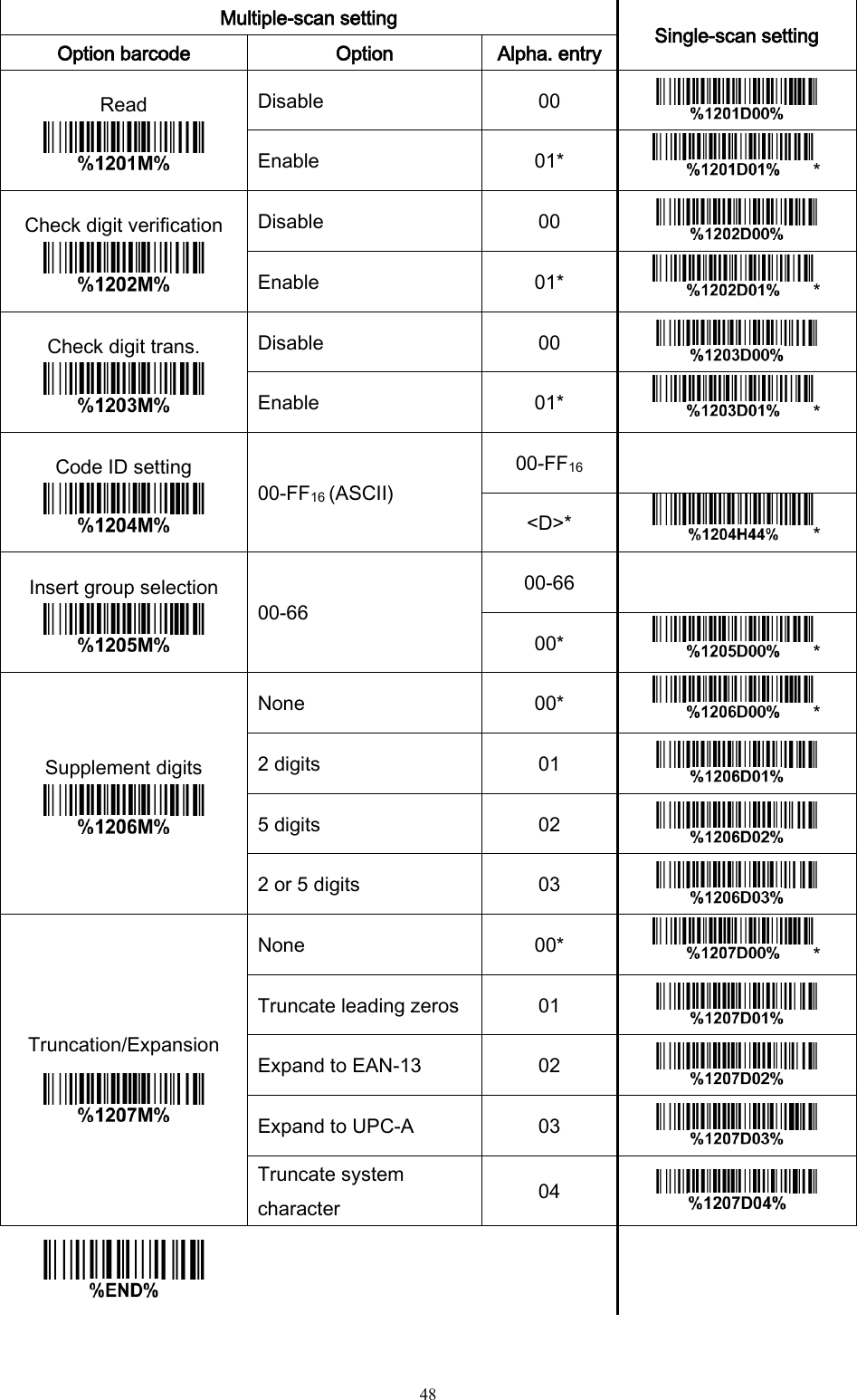
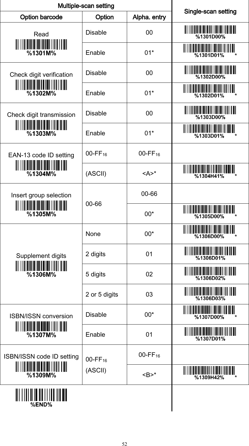
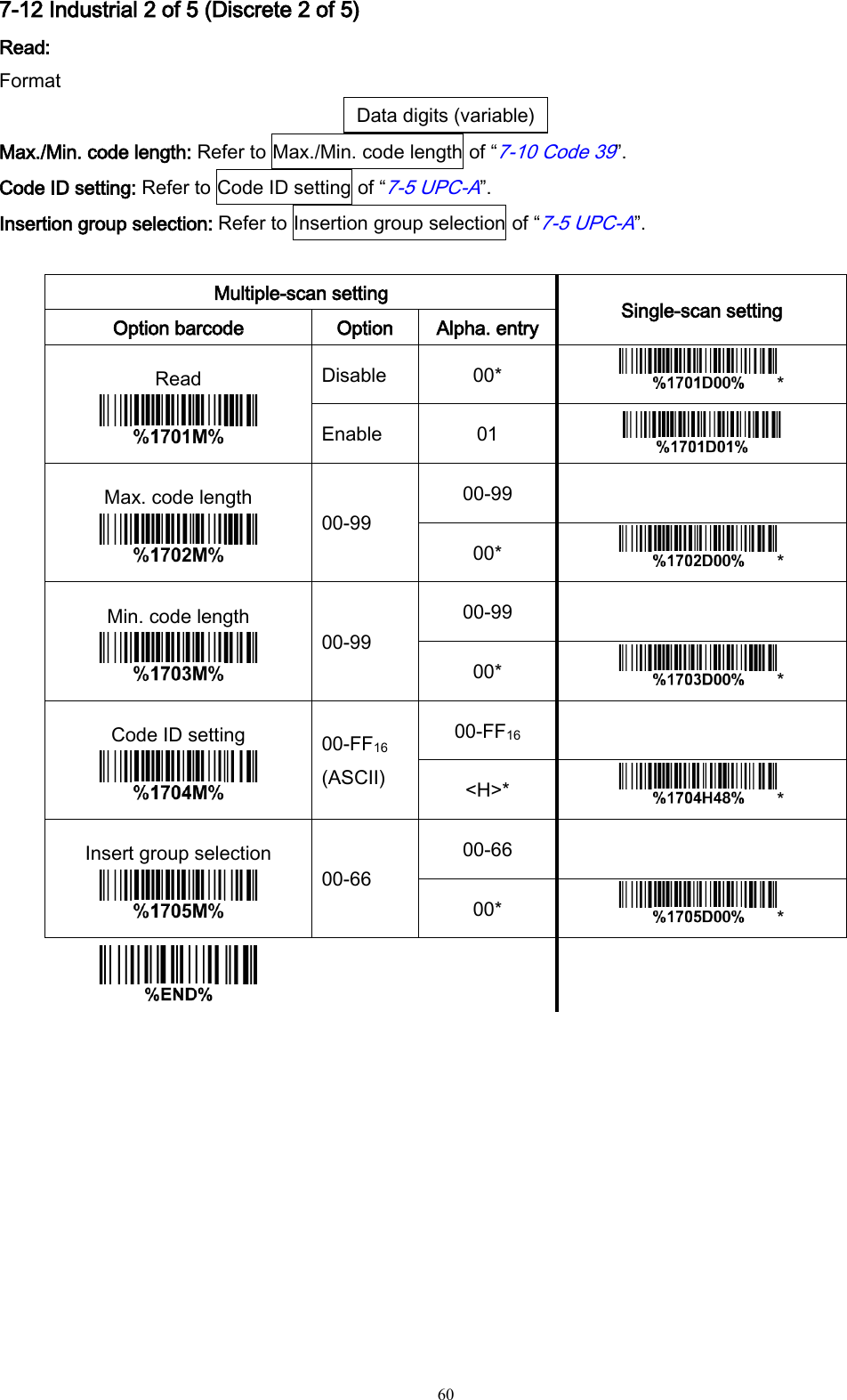
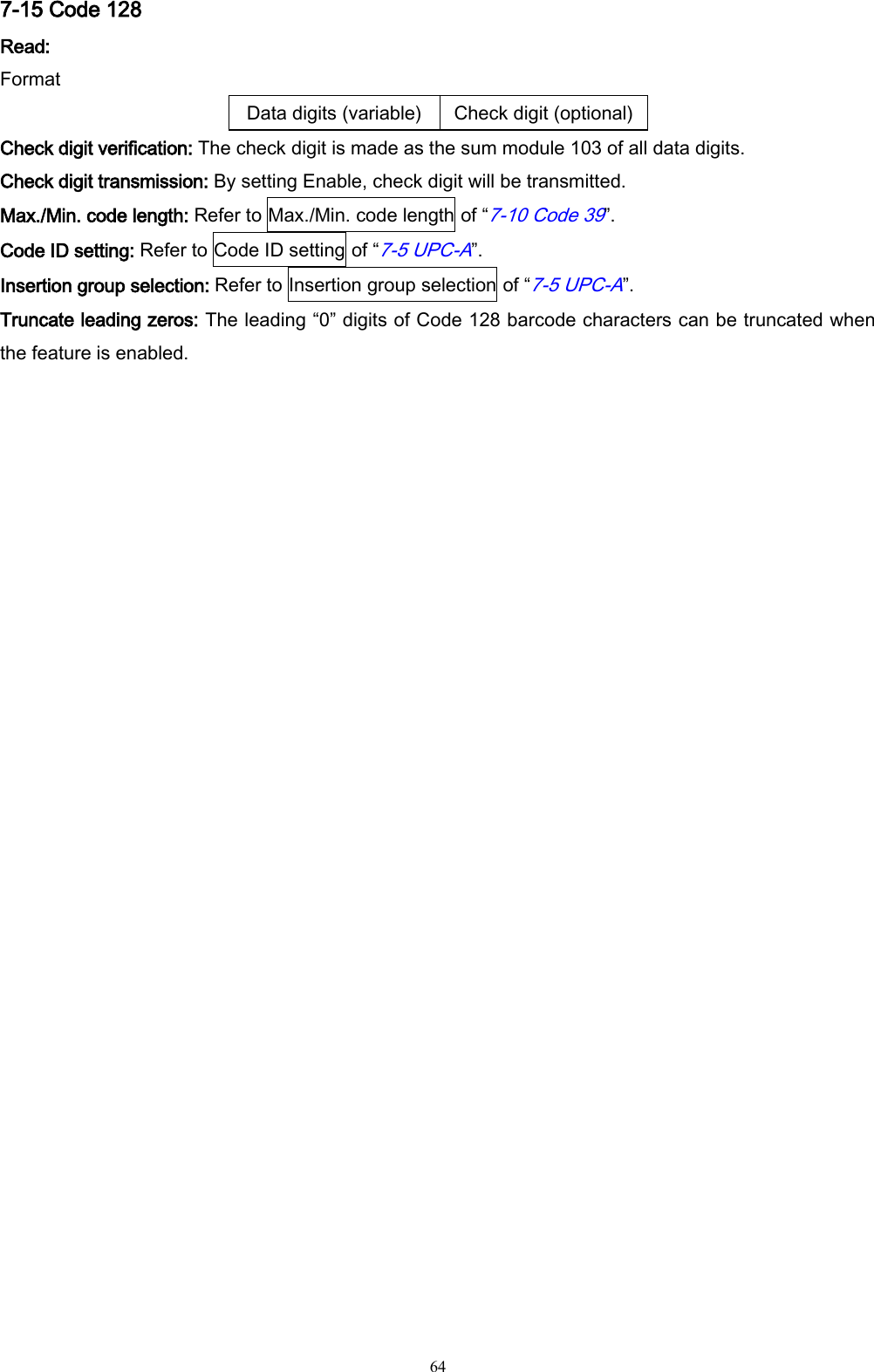
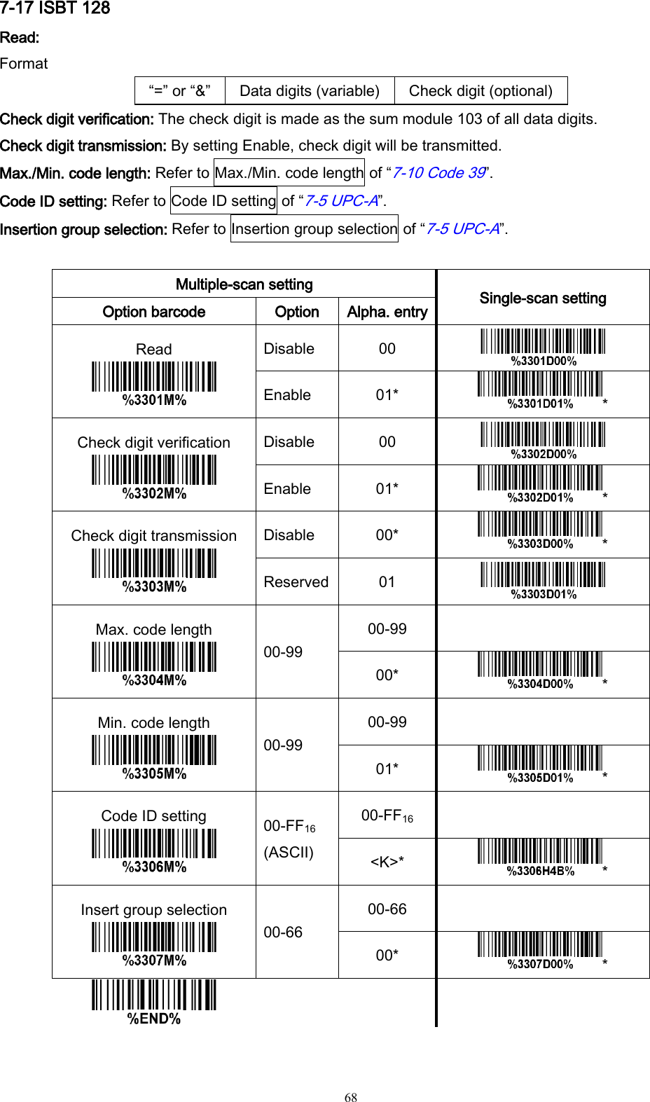
![24 Alternatively, you may go to Control Panel->Bluetooth Device. Step3. Click Add to search devices nearby. Step4. Click to select “My device is set up and ready to be found” and click Next. Step5. It takes a few seconds for the Wizard to search devices. The scanner will appear with its serial number as the device name. If the target scanner is seen on the list, click and select the target scanner. Click Next. If the target scanner does not appear on the list, click [Search Again] to refresh the list. Step6. Click and select “Let me choose my own passkey”. Enter a passkey for authentication and click Next.](https://usermanual.wiki/Minde-Electronics-Technology/MS3590/User-Guide-2349746-Page-31.png)
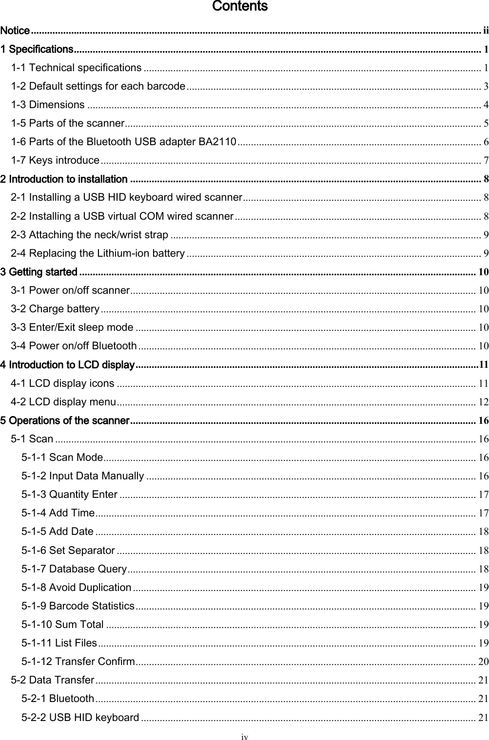
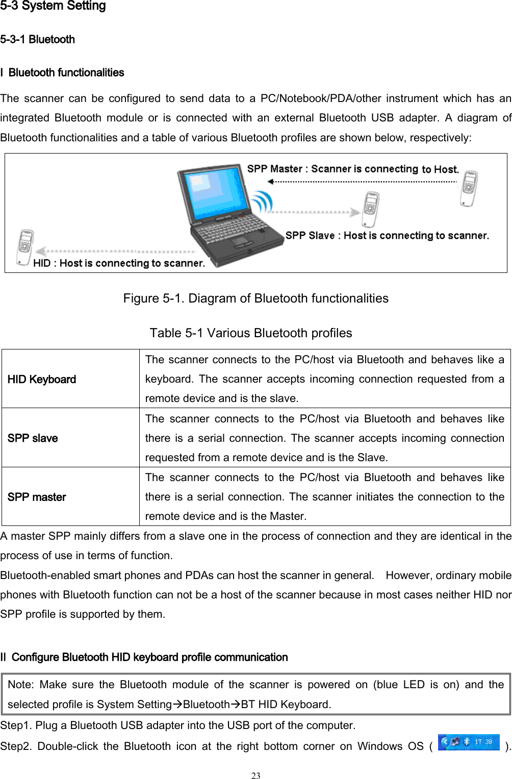
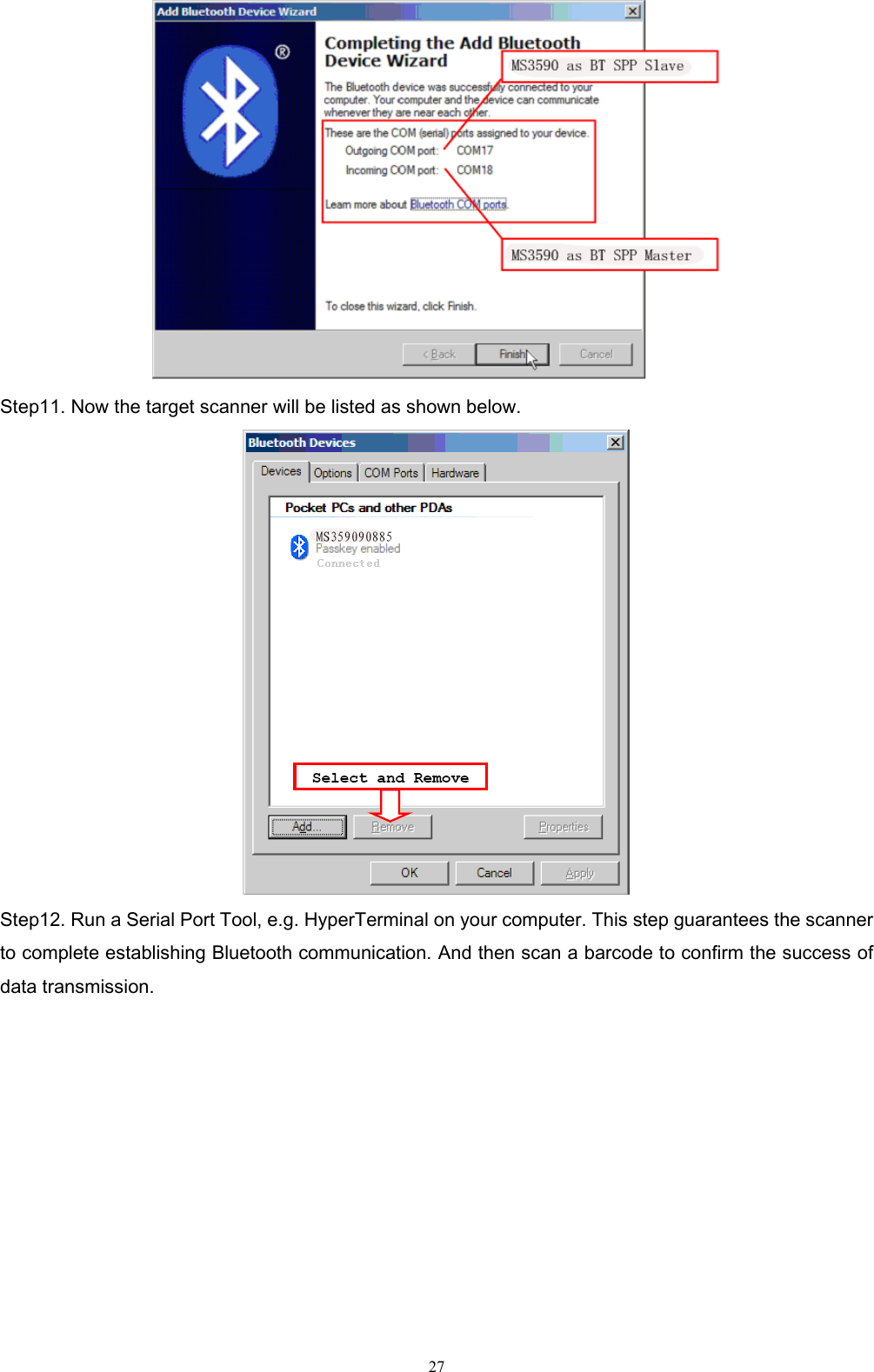
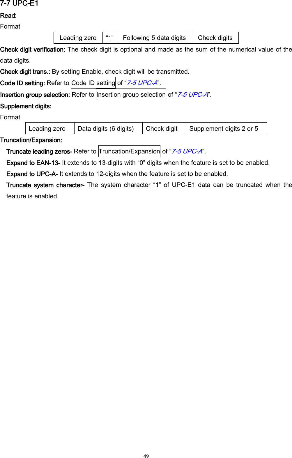
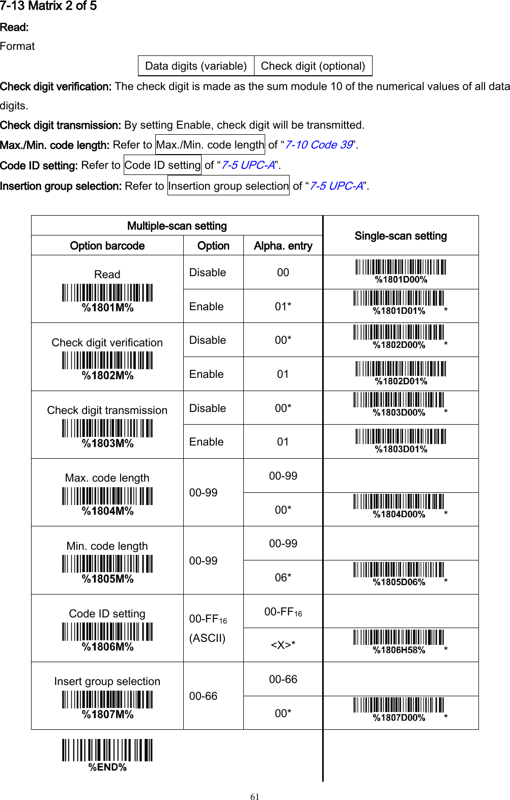
![26 Step12. Run the desired application, such as a Notepad and scan barcodes to check data transmission. Ⅲ Configure Bluetooth SPP slave profile communication Note: Make sure the Bluetooth module of the scanner is powered on (blue LED is on) and the selected profile is System SettingBluetoothBT SPP Slave. Step1-9: The same as Configure Bluetooth HID keyboard step 1~9. Step10. Click [Finish]](https://usermanual.wiki/Minde-Electronics-Technology/MS3590/User-Guide-2349746-Page-33.png)
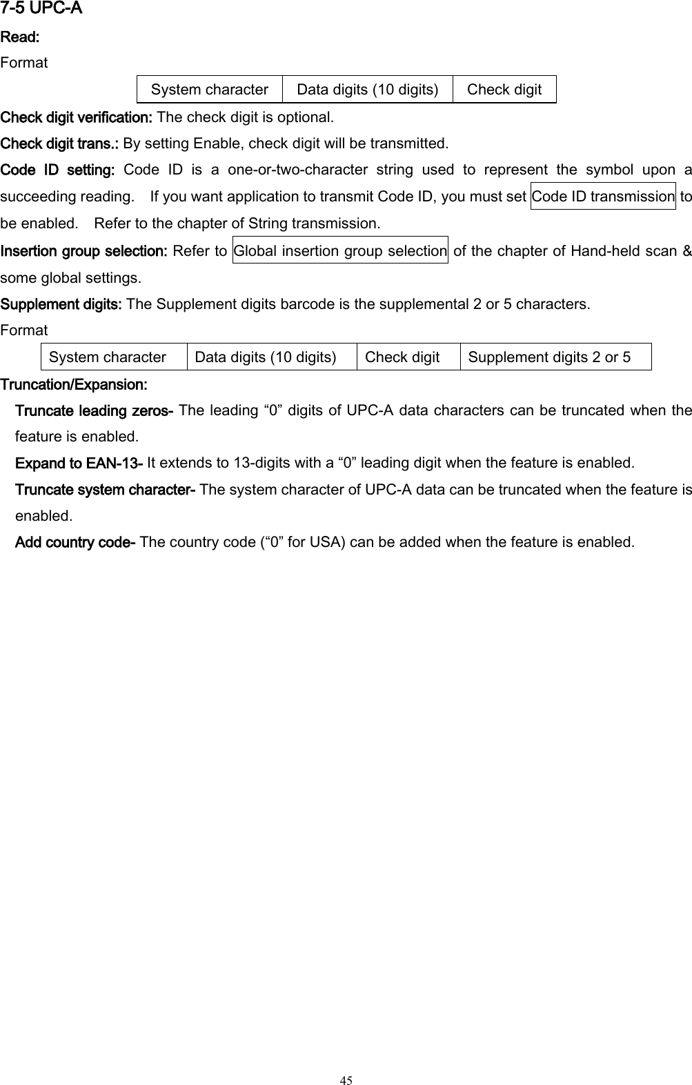
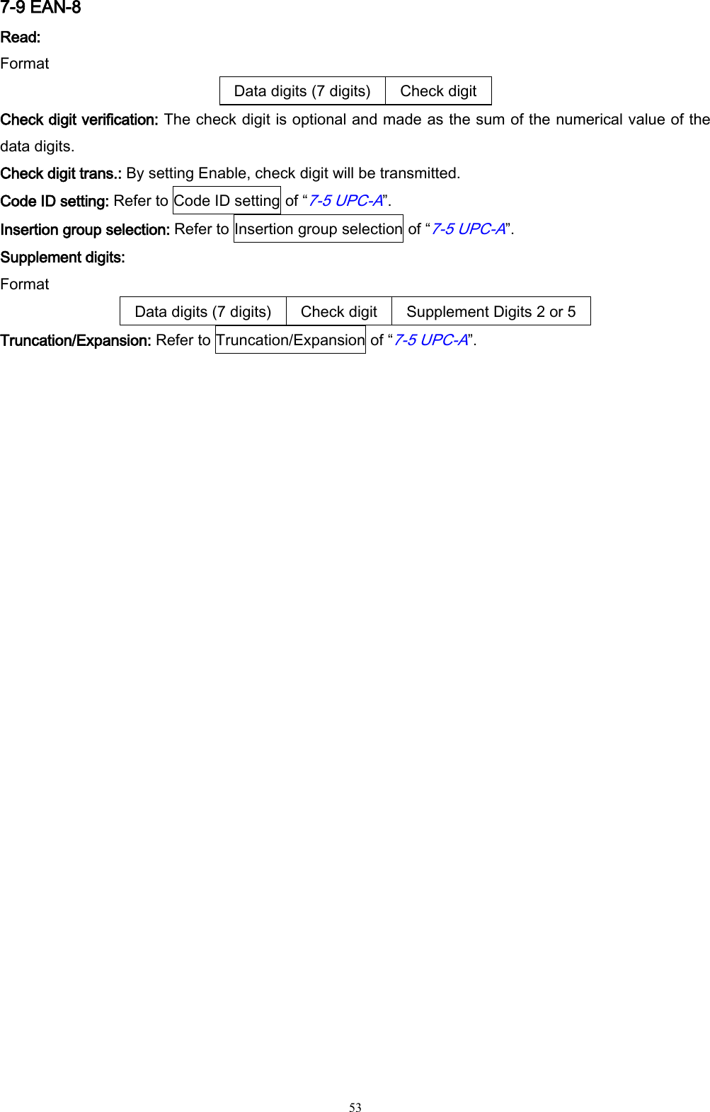
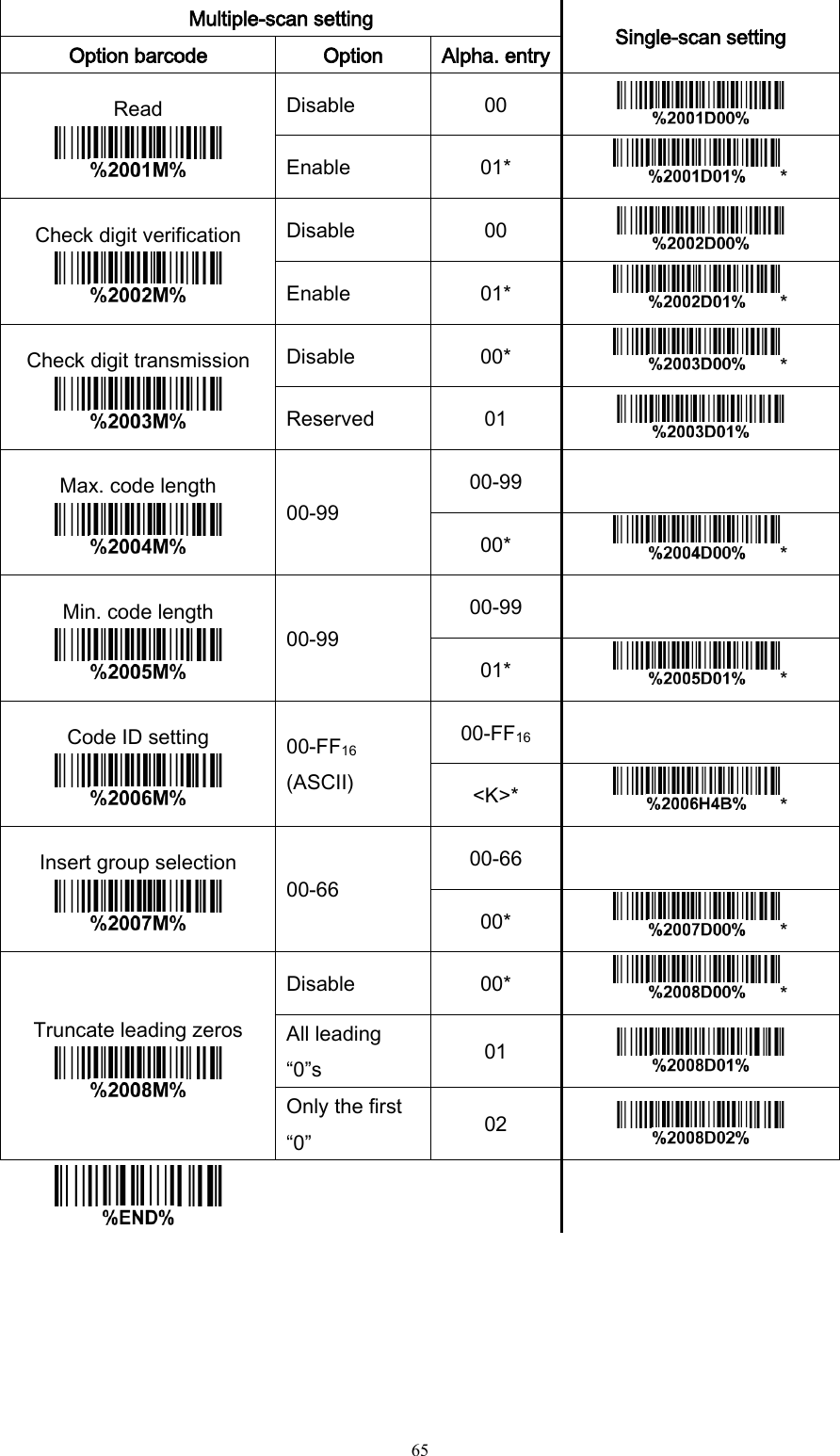
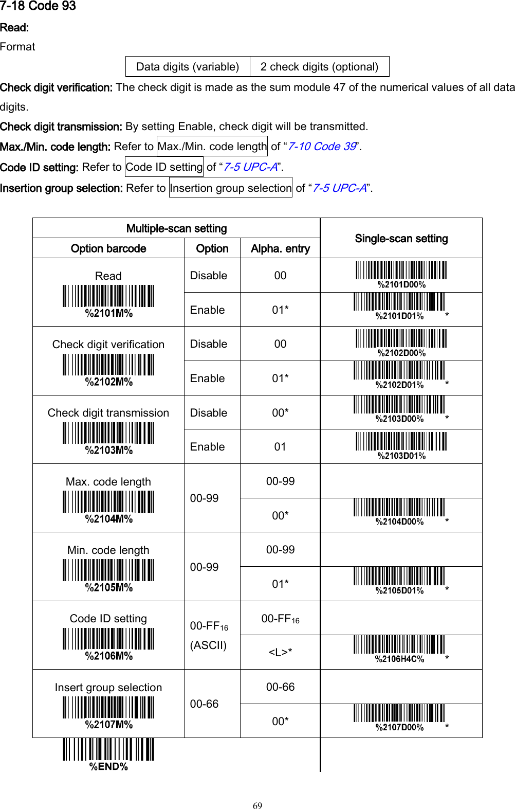
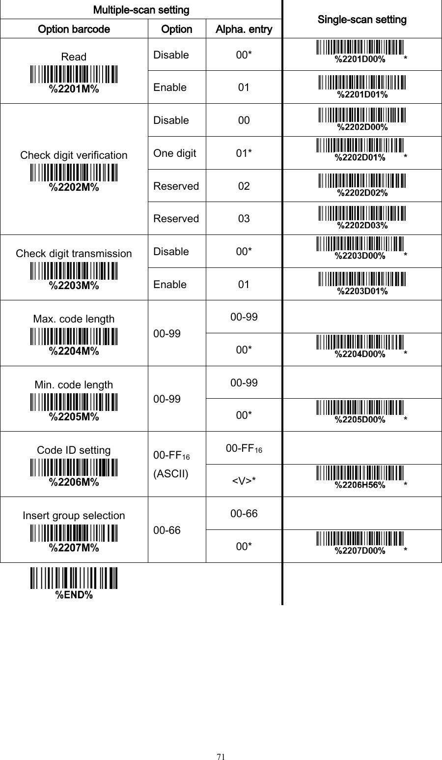
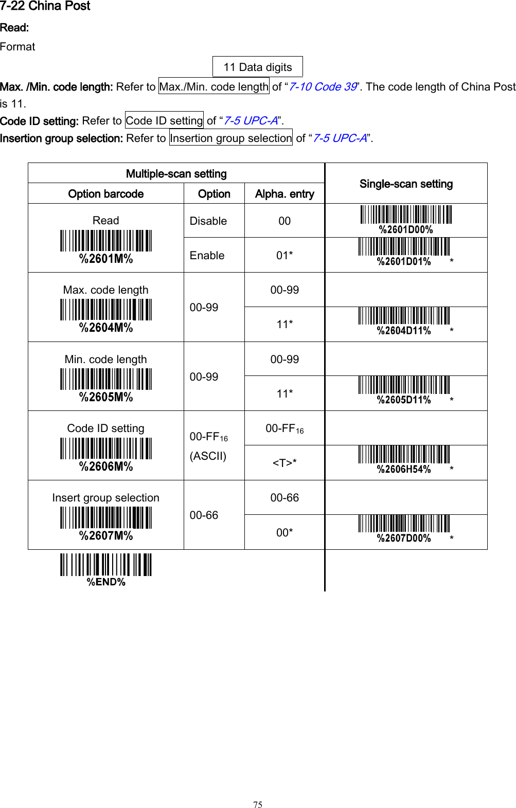
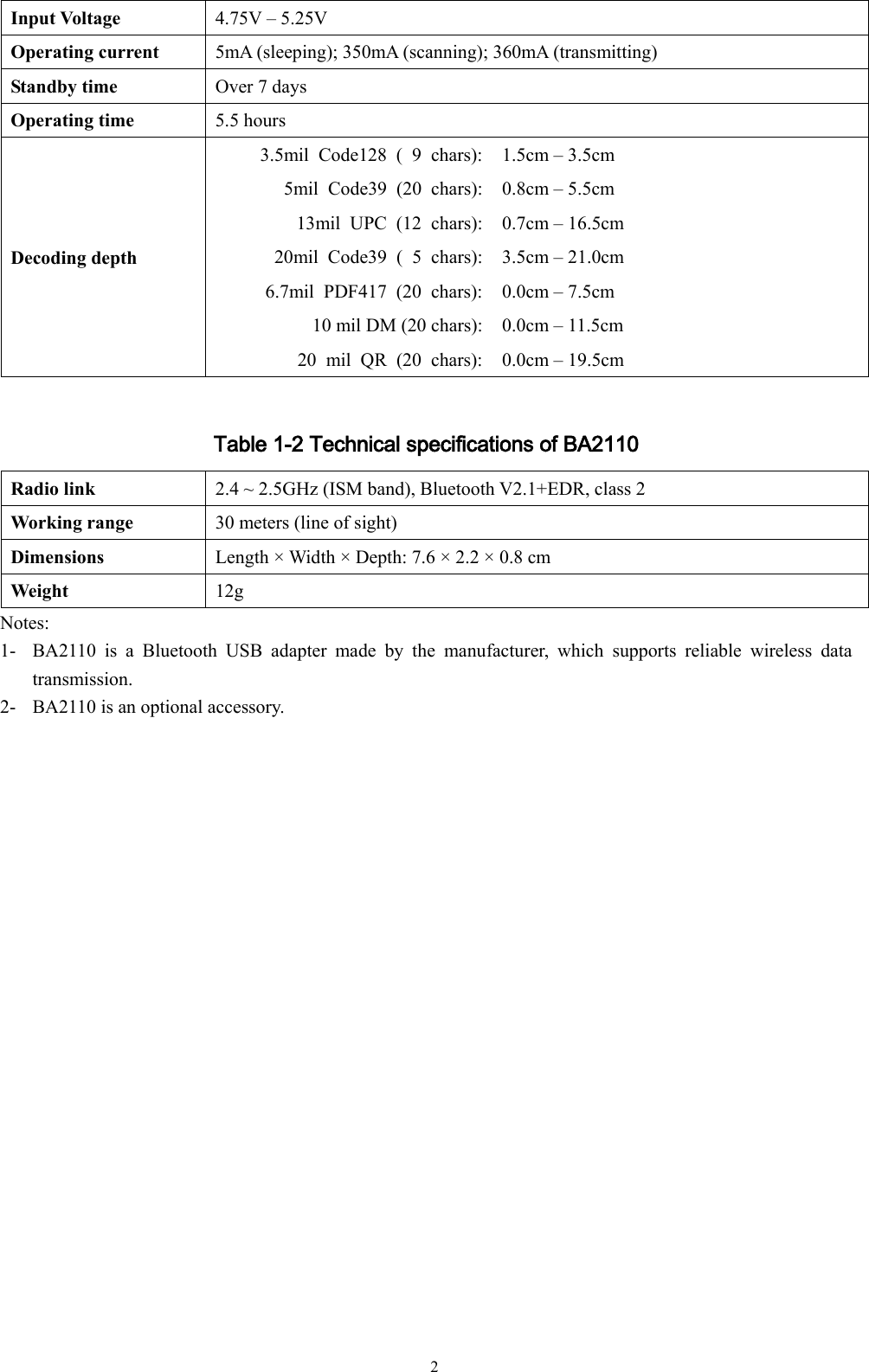
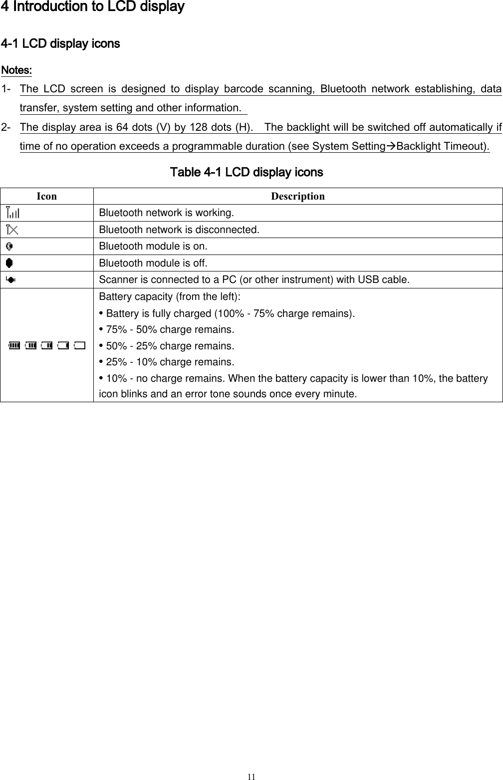
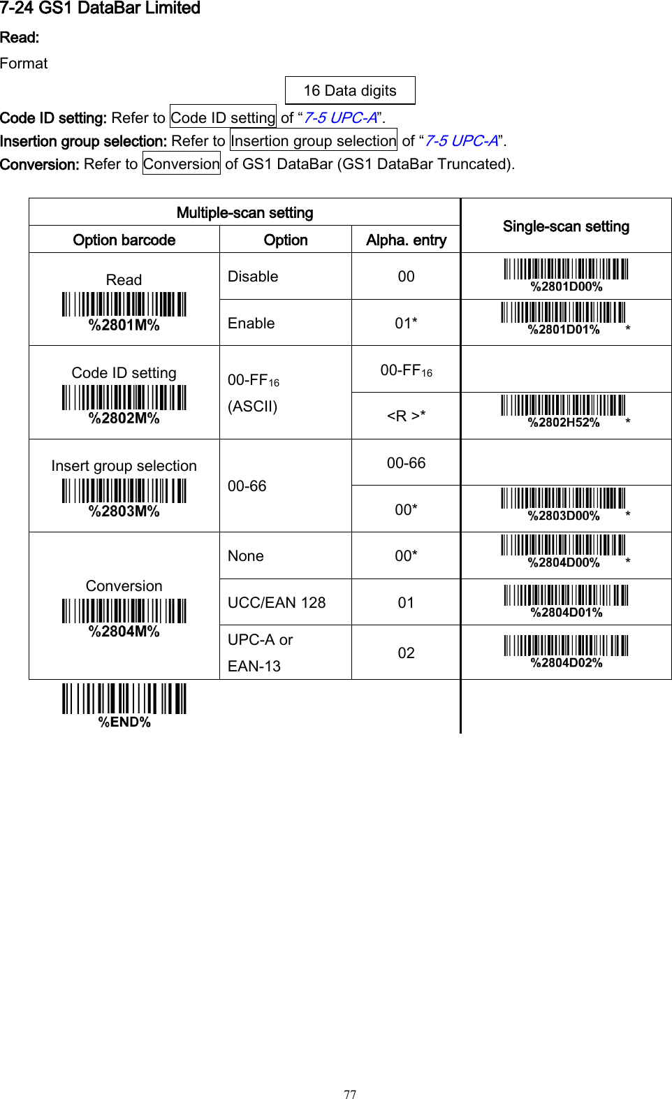
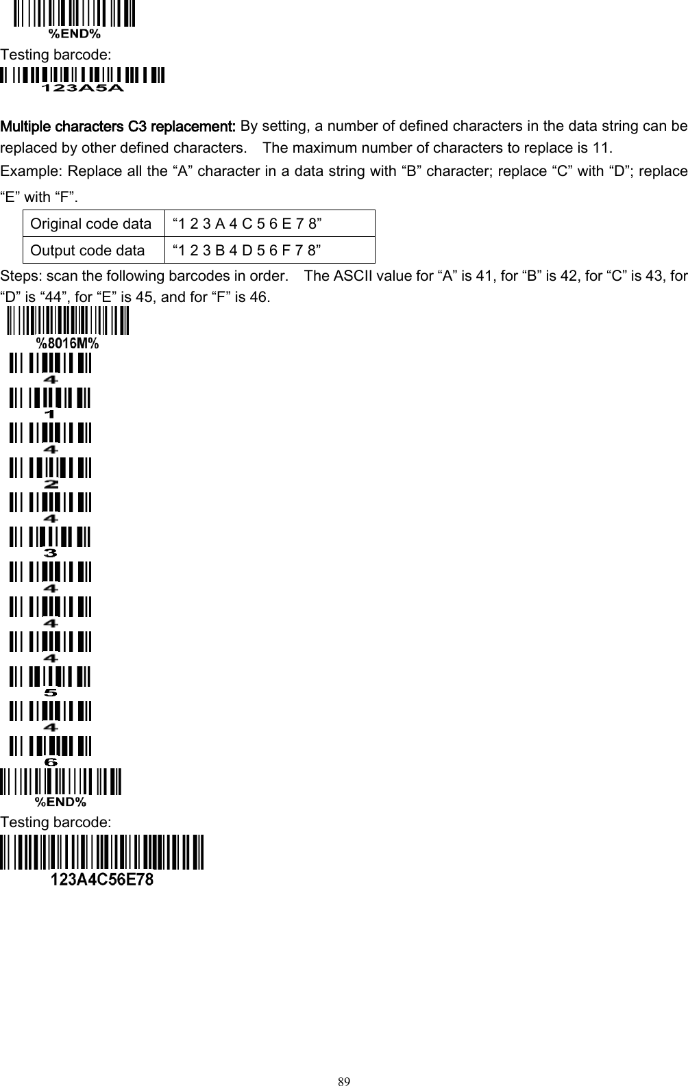
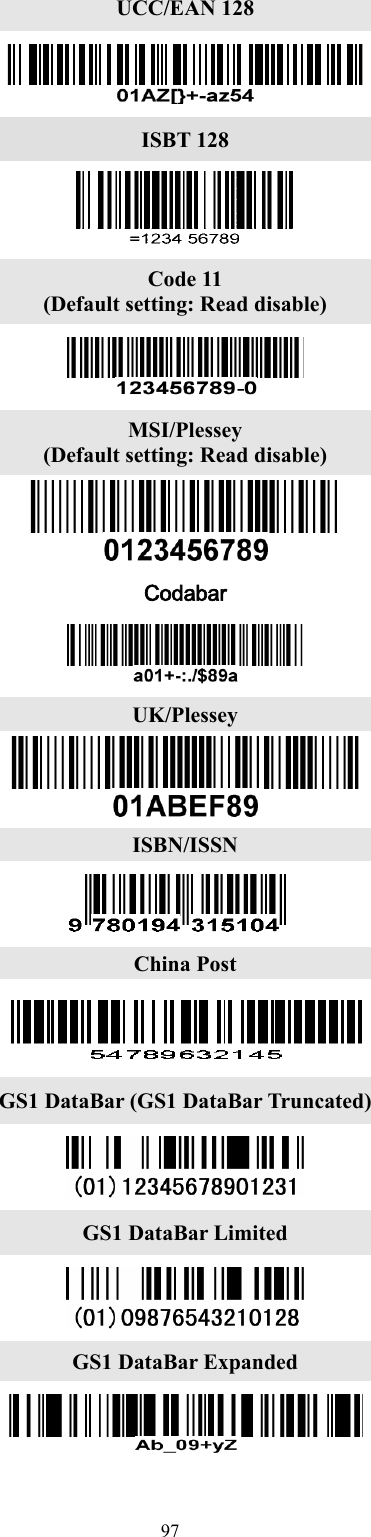
![76 7-23 GS1 DataBar (GS1 DataBar Truncated) GS1 DataBar Truncated is structured and encoded the same as the standard GS1 DataBar format, except its height is reduced to a 13 modules minimum; while GS1 DataBar should have a height greater than or equal to 33 modules. Read: Format 16 Data digits Code ID setting: Refer to Code ID setting of “7-5 UPC-A”. Insertion group selection: Refer to Insertion group selection of “7-5 UPC-A”. Conversion: UCC/EAN 128- Refer to Code ID transmission of String transmission, ]Cm will be identified as AIM ID. UPC-A or EAN-13- Barcode beginning with a single zero as the first digit has the leading “010” stripped and the barcode reported as EAN-13. Barcode beginning with two or more zeros but not six zeros has the leading “0100” stripped and the barcode reported as UPC-A. Multiple-scan setting Single-scan setting Option barcode Option Alpha. entry Read Disable 00 Enable 01* * Code ID setting 00-FF16 (ASCII) 00-FF16 <R >* * Insert group selection 00-66 00-66 00* * Conversion None 00* * UCC/EAN 128 01 UPC-A or EAN-13 02](https://usermanual.wiki/Minde-Electronics-Technology/MS3590/User-Guide-2349746-Page-83.png)
![78 7-25 GS1 DataBar Expanded Read: Format Data characters (variable) Code ID setting: Refer to Code ID setting of “7-5 UPC-A”. Insertion group selection: Refer to Insertion group selection of “7-5 UPC-A”. Conversion: UCC/EAN 128- Refer to Code ID transmission of String transmission, ]Cm will be identified as AIM ID. Multiple-scan setting Single-scan setting Option barcode Option Alpha. entry Read Disable 00 Enable 01* * Max. code length 00-99 00-99 00* * Min. code length 00-99 00-99 01* * Code ID setting 00-FF16 (ASCII) 00-FF16 <R >* * Insert group selection 00-66 00-66 00* * Conversion None 00* * UCC/EAN 128 01](https://usermanual.wiki/Minde-Electronics-Technology/MS3590/User-Guide-2349746-Page-85.png)


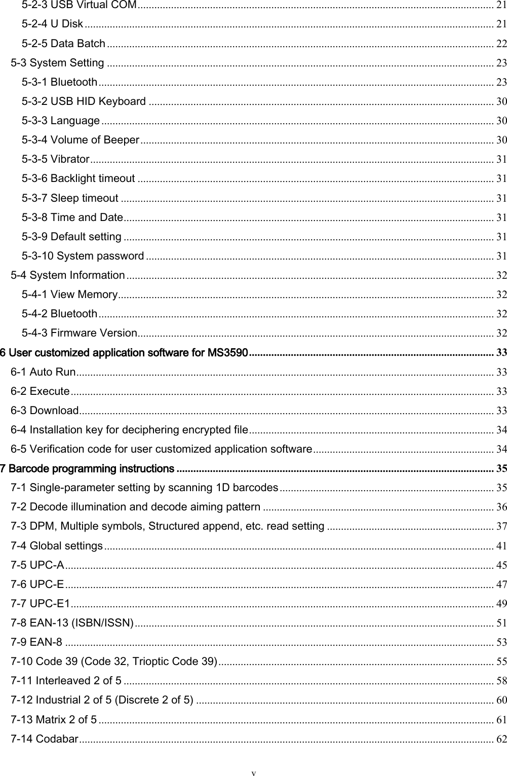
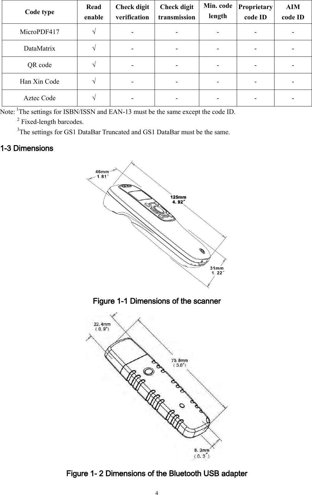
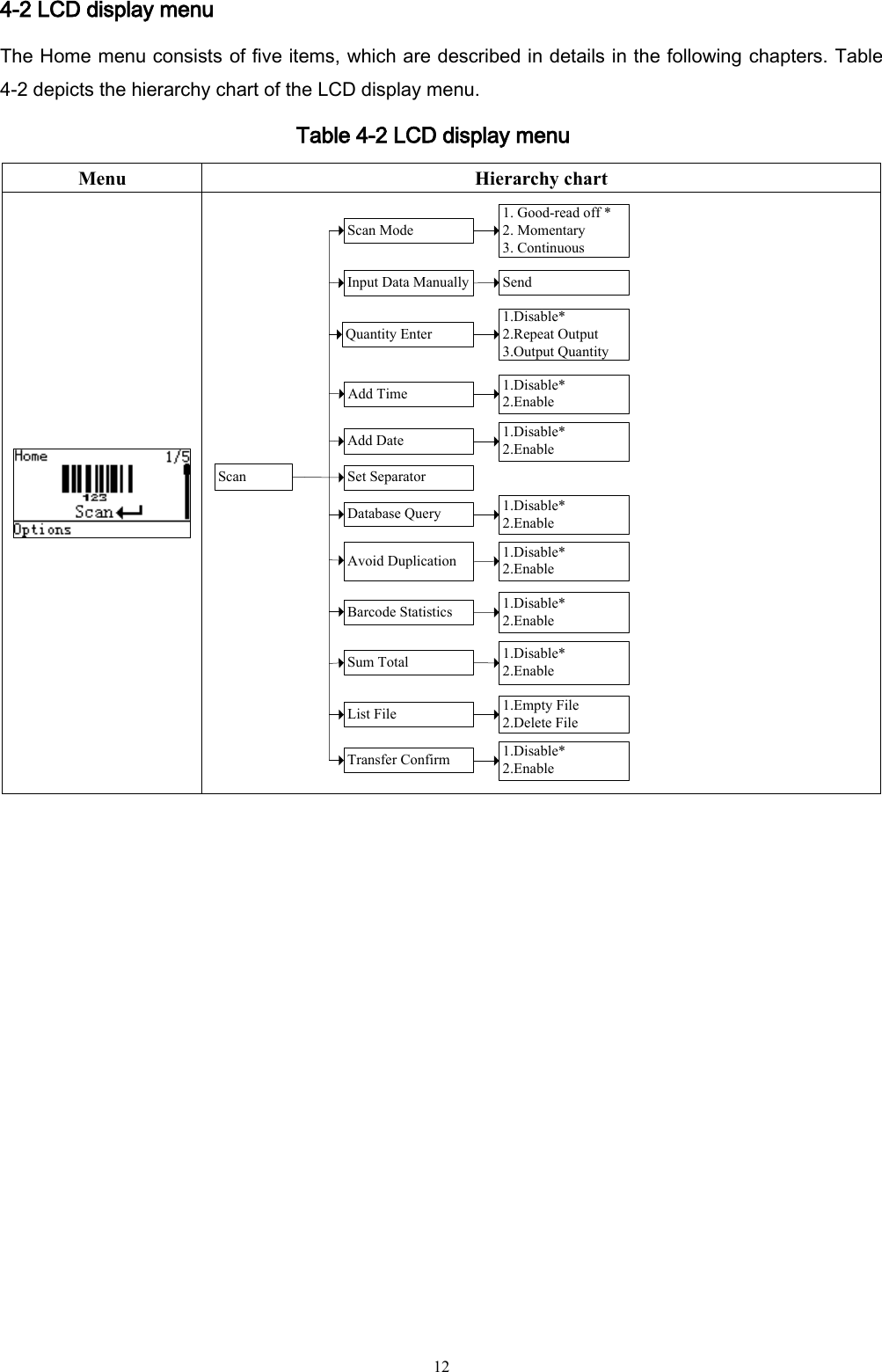
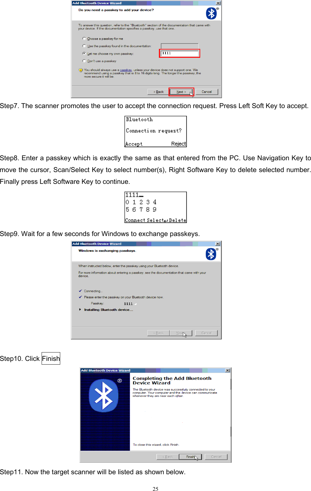
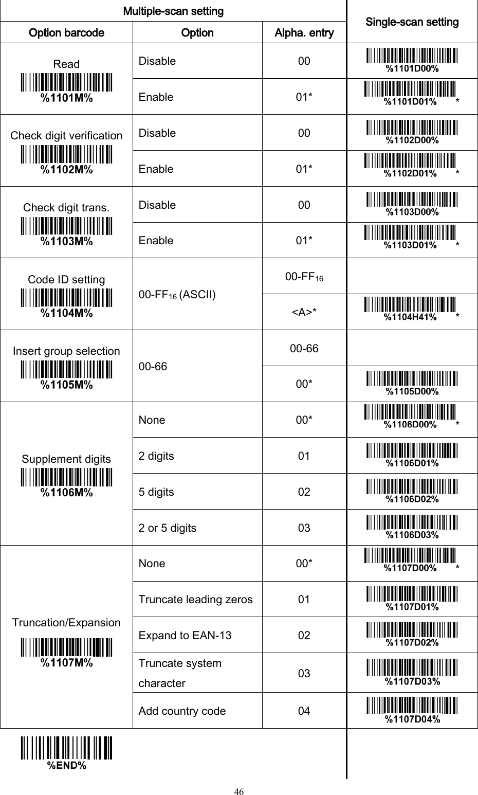
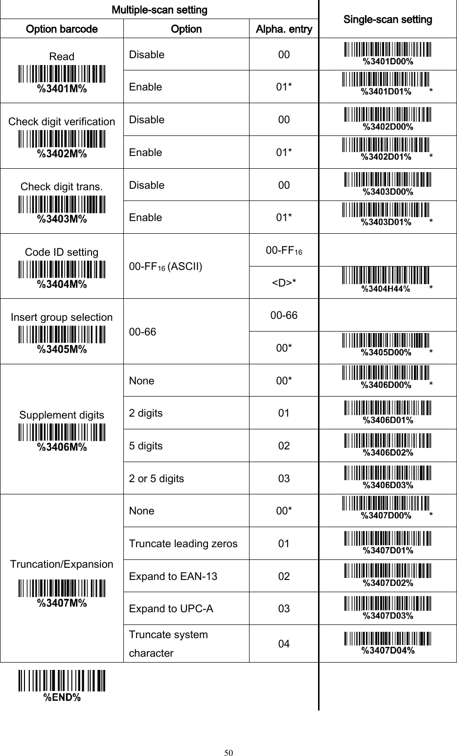
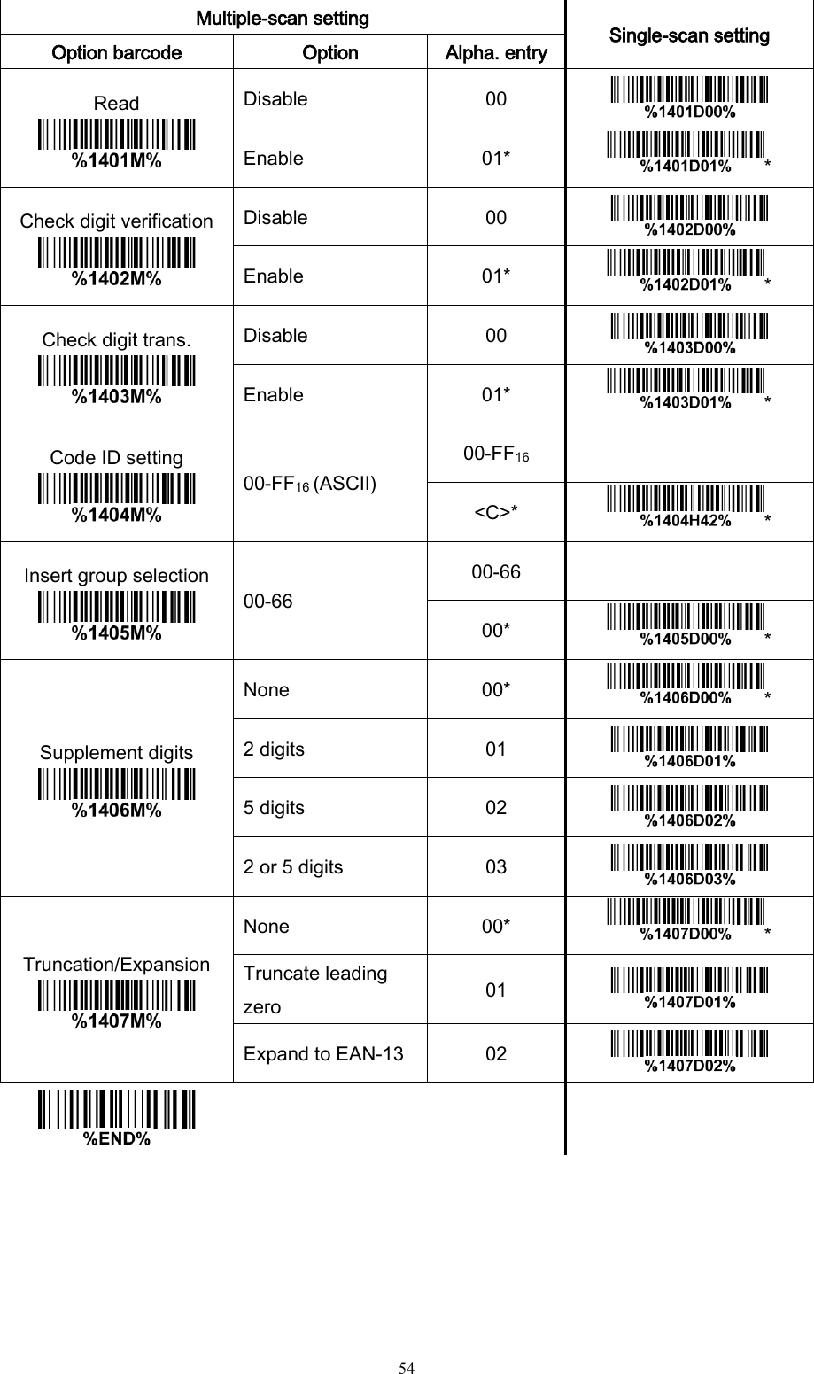
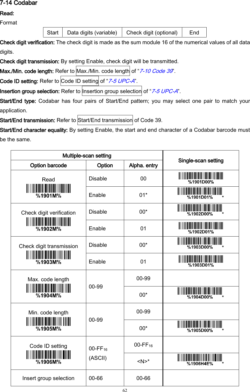
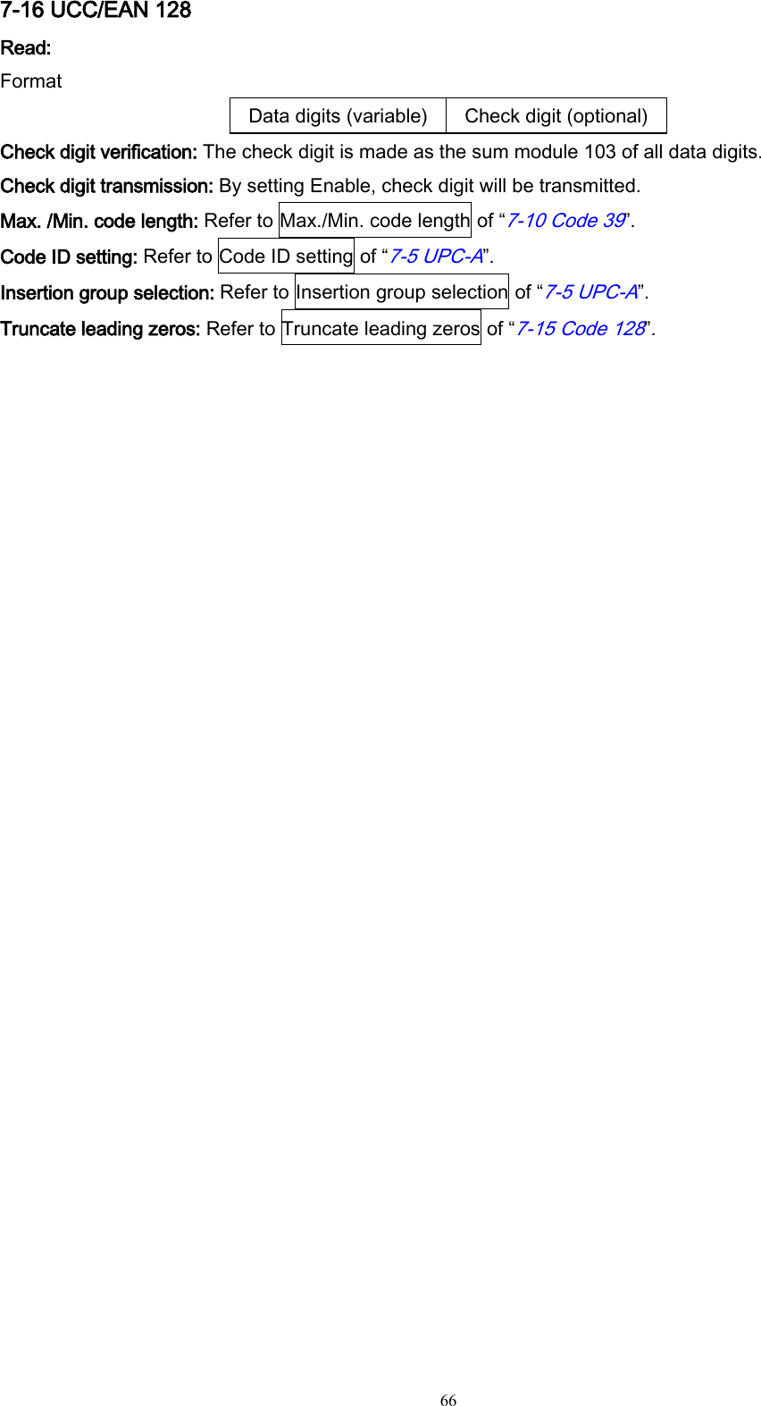
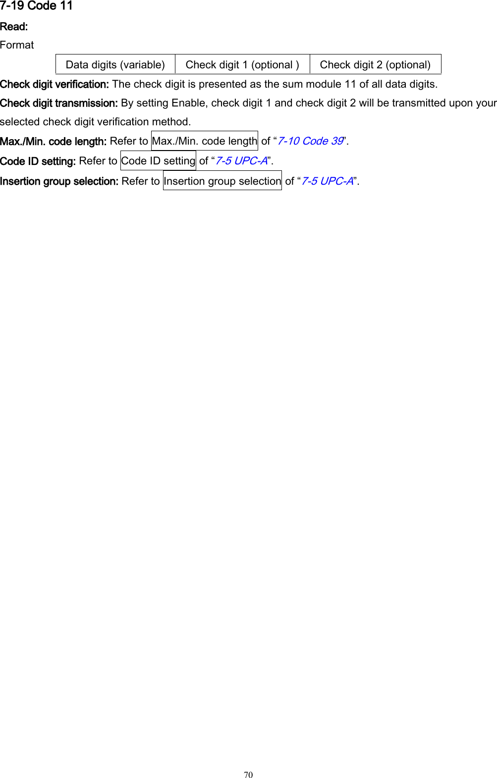
![99 9 ASCII Table for keyboard wedge for RS-232 H L 0 1 0 1 0 Null NUL DLE 1 Up F1 SOH DC1 2 Down F2 STX DC2 3 Left F3 ETX DC3 4 Right F4 EOT DC4 5 PgUp F5 ENQ NAK 6 PgDn F6 ACK SYN 7 F7 BEL ETB 8 Bs F8 BS CAN 9 Tab F9 HT EM A F10 LF SUB B Home Esc VT ESC C End F11 FF FS D Enter F12 CR GS E Insert Ctrl+ SO RS F Delete Alt+ SI US Notes: The 2nd and the 3rd columns above are used for keyboard wedge only. H L 2 3 4 5 6 7 0 SP 0 @ P ` p 1 ! 1 A Q a q 2 “ 2 B R b r 3 # 3 C S c s 4 $ 4 D T d t 5 % 5 E U e u 6 & 6 F V f v 7 ‘ 7 G W g w 8 ( 8 H X h x 9 ) 9 I Y i y A * : J Z j z B + ; K [ k { C , < L \ l | D - = M ] m } E . > N ^ n ~ F / ? O _ o DEL Example: ASCII “A” = “41”.](https://usermanual.wiki/Minde-Electronics-Technology/MS3590/User-Guide-2349746-Page-106.png)