Mindray BIO Medical electronics TMS6016 Telemetry Monitoring Transmitter User Manual h39887 21 operator s manual

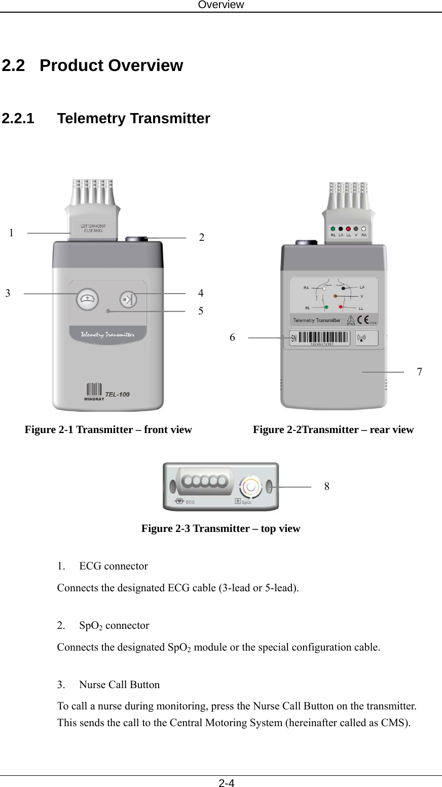
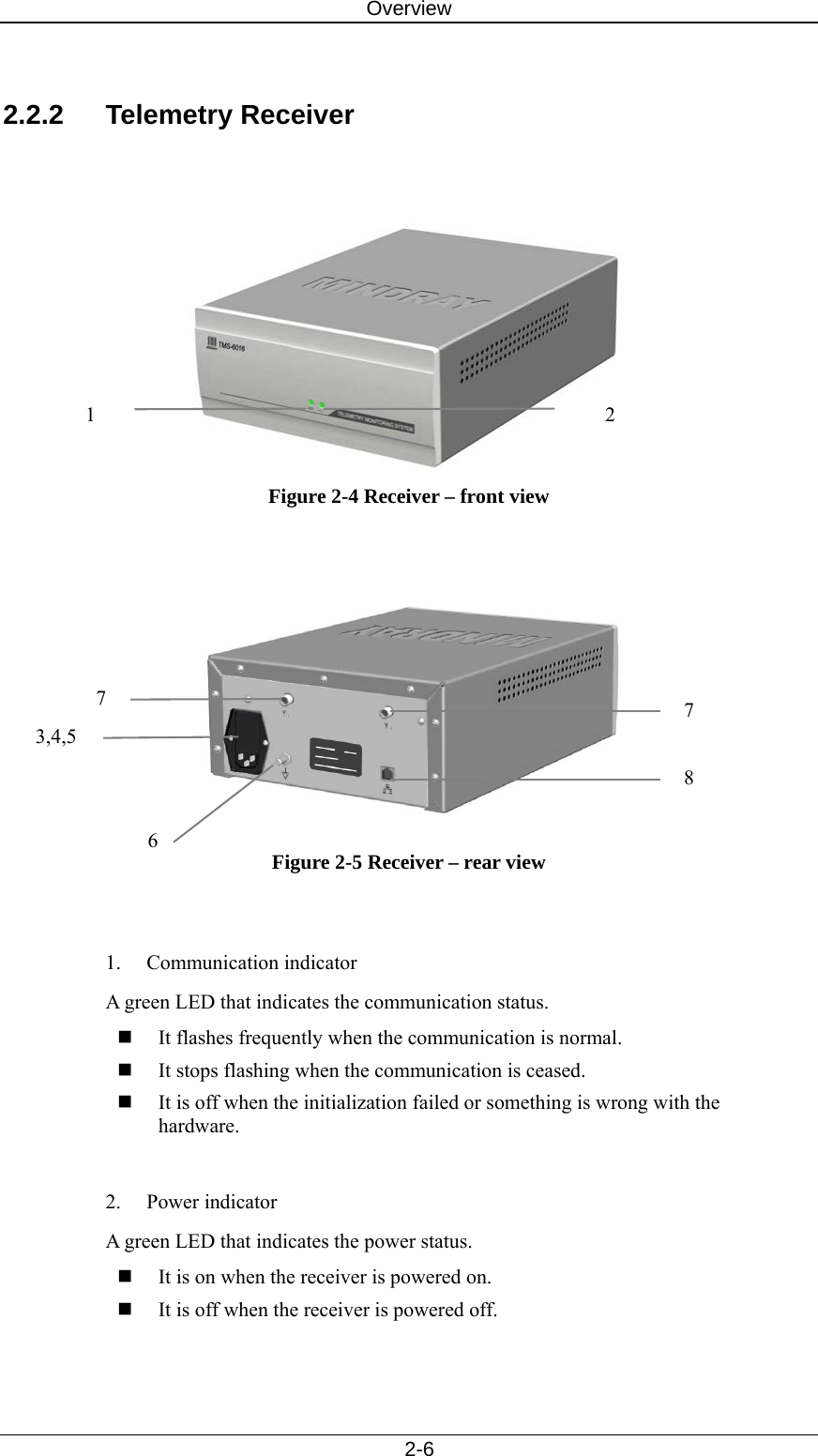
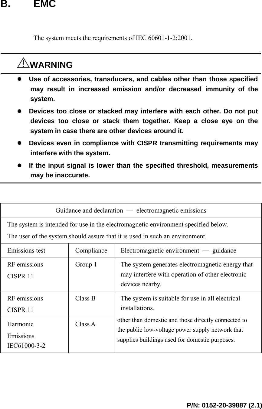
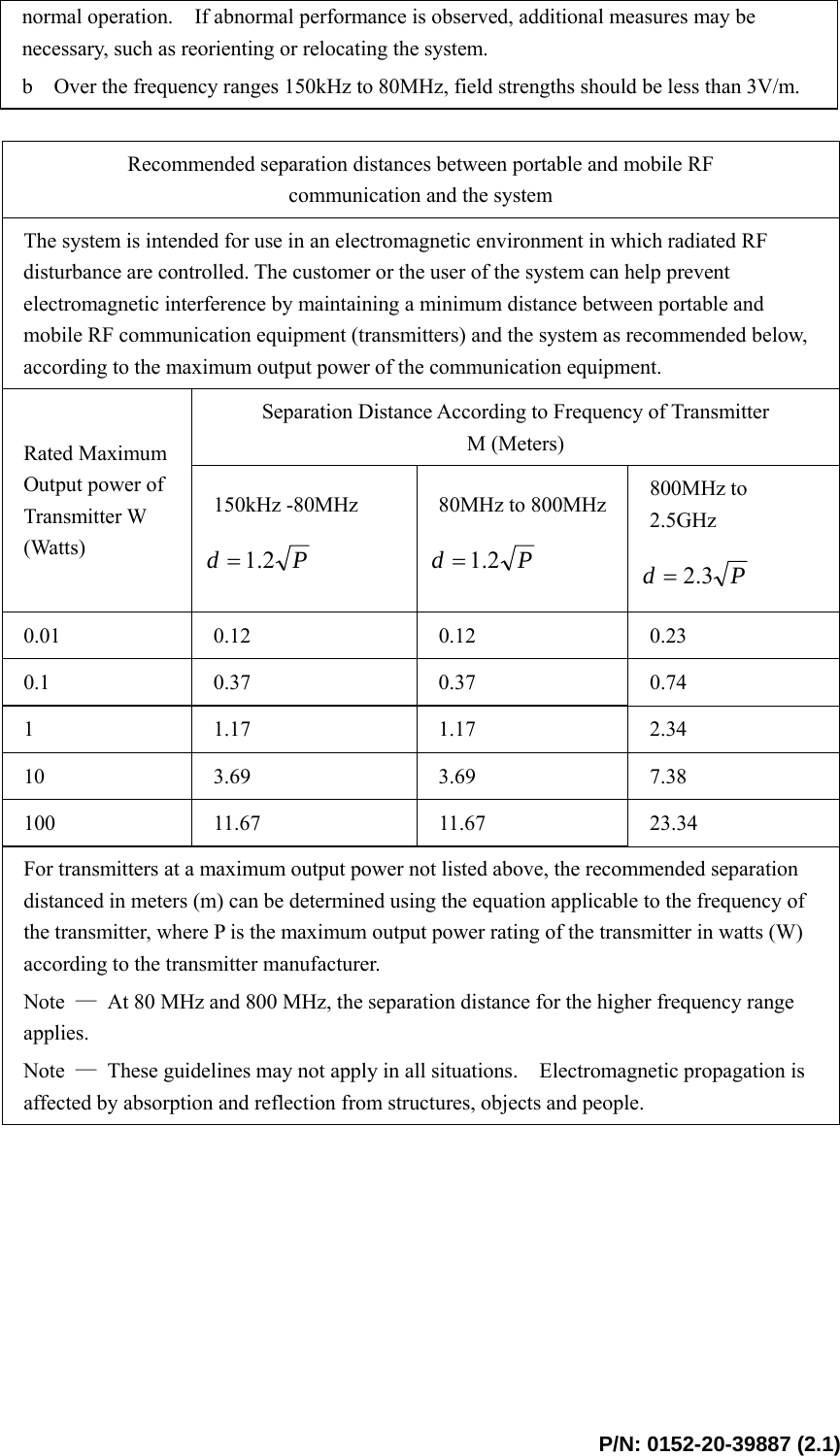
SHENZHEN MINDRAY BIO-MEDICAL ELECTRONICS CO., LTD. Telemetry Monitoring Transmitter h39887 21 operator s manual

user manual

       TMS-6016    Telemetry Monitoring System     Operation Manual
 I  CE Marking     The telemetry monitoring system bears CE mark indicating its conformity with the provisions of the Council Directive 93/42/EEC concerning medical devices and fulfils the essential requirements of Annex I of this directive.  The telemetry monitoring system is in radio-interference protection class B in accordance with EN55011.  The product complies with the requirement of standard EN60601-1-2 “Electromagnetic Compatibility – Medical Electrical Equipment”.   Revision History  This manual has a revision number. This revision number changes whenever the manual is updated due to software or technical specification change. Contents of this manual are subject to change without prior notice. Revision 1.0 is the initial release of the document.  Version number:  2.1  Release time:  November 2006 © 2005 - 2006 Shenzhen Mindray Bio-Medical Electronics Co., Ltd. All rights reserved.     WARNING z Federal Law (USA) restricts this device to sale by or on the order of a physician.
    II  Intellectual Property Statement   SHENZHEN MINDRAY BIO-MEDICAL ELECTRONICS CO., LTD. (hereinafter called Mindray) owns the intellectual property rights to this product and this manual. This manual may refer to information protected by copyrights or patents and does not convey any license under the patent rights of Mindray, nor the rights of others. Mindray does not assume any liability arising out of any infringements of patents or other rights of third parties.  Mindray intends to maintain the contents of this manual as confidential information. Disclosure of the information in this manual in any manner whatsoever without the written permission of Mindray is strictly forbidden. Release, amendment, reproduction, distribution, rent, adaption and translation of this manual in any manner whatsoever without the written permission of Mindray is strictly forbidden.   and    are the registered trademarks or trademarks owned by Mindray in China and other countries. All other trademarks that appear in this manual are used only for editorial purposes without the intention of improperly using them. They are the property of their respective owners.  Contents of this manual are subject to changes without prior notice.
    III  Manufacturer’s Responsibility   All information contained in this manual is believed to be correct. Mindray shall not be liable for errors contained herein nor for incidental or consequential damages in connection with the furnishing, performance, or use of this manual.  Mindray is responsible for safety, reliability and performance of this product only in the condition that:  All installation operations, expansions, changes, modifications and repairs of this product are conducted by Mindray authorized personnel; and  The electrical installation of the relevant room complies with the applicable national and local requirements; and  This product is operated under strict observance of this manual.   Warranty  This warranty is exclusive and is in lieu of all other warranties, expressed or implied, including warranties of merchantability or fitness for any particular purpose.   Exemptions  Mindray's obligation or liability under this warranty does not include any transportation or other charges or liability for direct, indirect or consequential damages or delay resulting from the improper use or application of the product or the use of parts or accessories not approved by Mindray or repairs by people other than Mindray authorized personnel.  This warranty shall not extend to  Any Mindray product which has been subjected to misuse, negligence or accident; or  Any Mindray product from which Mindray's original serial number tag or product identification markings have been altered or removed; or  Any product of any other manufacturer.
    IV  Return Policy   In the event that it becomes necessary to return a unit to Mindray, follow the instructions below.  1.  Obtain a return authorization. Contact the Mindray Service Department and obtain a Mindray Customer Service Authorization Number. The Mindray Customer Service Authorization Number must appear on the outside of the shipping container. Return shipments will not be accepted if the Mindray Customer Service Authorization Number is not clearly visible. Please provide the model number, serial number, and a brief description of the reason for return.  2. Freight policy The customer is responsible for freight charges when this product is shipped to Mindray for service (including any relevant customs fees or other freight related charges).  3. Return address Please send the part(s) or equipment to the address offered by Customer Service Department.  Contact Information   Manufacturer:  Shenzhen Mindray Bio-Medical Electronics Co., Ltd. Address:  Mindray Building, Keji 12th Road South, Hi-tech Industrial Park, Nanshan, Shenzhen 518057 P.R. China Tel:  +86 755 26582479     +86 755 26582888 Fax:  +86 755 26582934     +86 755 26582500 Website: www.mindray.com   EC-Representative: Shanghai International Holding Corp. GmbH (Europe) Address:  Eiffestraße 80, 20537 Hamburg Germany Tel: 0049-40-2513175 Fax: 0049-40-255726
    V  Preface   Manual Purpose  This manual contains the instructions necessary to operate the telemetry monitoring system safely and in accordance with its function and intended use. Observance of this manual is a prerequisite for proper product performance and correct operation and ensures patient and operator safety.    This manual is based on the maximum configuration and therefore some contents may not apply to your telemetry monitoring system. If you have any question, please contact us.  This manual is an integral part of the product. It should always be kept close to the equipment so that it can be obtained conveniently when needed.  Intended Audience  This manual is geared for clinical professionals who are expected to have a working knowledge of medical procedures, practices and terminology as required for monitoring of critically ill patients.  Illustrations  All illustrations in this manual serve as examples only. They may not necessarily reflect your monitoring setup or data displayed on your telemetry monitoring system.  Conventions   Italic text is used in this manual to quote the referenced chapters or sections.  The terms danger, warning, and caution are used throughout this manual to point out hazards and to designate a degree or level or seriousness.
    VI  FOR YOUR NOTES
 1  Contents     1 Safety.................................................................................................................... 1-1 1.1 Safety Information ...................................................................................... 1-2 1.1.1 Dangers ......................................................................................... 1-3 1.1.2 Warnings........................................................................................ 1-3 1.1.3 Cautions......................................................................................... 1-4 1.1.4 Notes ............................................................................................. 1-5 1.2 Equipment Symbols .................................................................................... 1-6 1.3 Reference Literature.................................................................................... 1-8 2 Overview .............................................................................................................. 2-1 2.1 General ........................................................................................................ 2-2 2.1.1 Intended Use.................................................................................. 2-2 2.1.2 Contraindications .......................................................................... 2-3 2.1.3 Components................................................................................... 2-3 2.1.4 Functions ....................................................................................... 2-3 2.2 Product Overview........................................................................................ 2-4 2.2.1 Telemetry Transmitter ................................................................... 2-4 2.2.2 Telemetry Receiver ....................................................................... 2-6 2.3 About the CMS ........................................................................................... 2-8 2.3.1 Main Screen .................................................................................. 2-8 2.3.2 Auxiliary Screen in Single-Screen Mode.....................................2-11 2.3.3 ViewBed Screen .......................................................................... 2-12 3 Installation and Maintenance............................................................................. 3-1 3.1 Installation................................................................................................... 3-2 3.1.1 Unpacking and Inspection ............................................................. 3-2 3.1.2 Environmental Requirements........................................................ 3-3 3.1.3 Power Requirements ..................................................................... 3-3 3.1.4 Computer Requirements................................................................ 3-4 3.1.5 Installation..................................................................................... 3-5 3.1.6 Starting the system ........................................................................ 3-6 3.1.7  Shutting down the system ............................................................. 3-7 3.2 Maintenance ................................................................................................ 3-8 3.2.1 Inspection ...................................................................................... 3-8 3.2.2 Cleaning ........................................................................................ 3-9 3.2.3 Disinfection and Sterilization.......................................................3-11
Contents   2 4 Using Transmitters.............................................................................................. 4-1 4.1  Installing and replacing batteries................................................................. 4-2 4.2  Switching on/off the transmitter.................................................................. 4-3 4.3 Wearing the transmitter ............................................................................... 4-3 5 Routine CMS Operation..................................................................................... 5-1 5.1 Nurse call .................................................................................................... 5-2 5.2 Event ........................................................................................................... 5-2 5.3 STANDBY mode ........................................................................................ 5-2 5.4 Patient Management.................................................................................... 5-3 5.4.1  Admitting a Patient........................................................................ 5-3 5.4.2 Editing patient information ........................................................... 5-4 5.4.3 Discharging a Patient..................................................................... 5-5 5.5 Alarm Setup ................................................................................................ 5-6 5.5.1 Alarm Setup .................................................................................. 5-6 5.5.2 Alarm Volume ............................................................................... 5-7 5.5.3 Pause alarm ................................................................................... 5-8 5.5.4 Alarm Latching ............................................................................. 5-8 5.5.5  Turning off alarm sound................................................................ 5-9 5.6 Review ...................................................................................................... 5-10 5.7 Record ....................................................................................................... 5-14 5.8 Print........................................................................................................... 5-15 6 ECG Monitoring.................................................................................................. 6-1 6.1 Preparation .................................................................................................. 6-2 6.2 Electrode Placement.................................................................................... 6-3 6.3 ECG Monitoring.......................................................................................... 6-8 6.3.1 ECG waveform.............................................................................. 6-8 6.3.2 ECG parameter.............................................................................. 6-9 6.3.3 ECG Setup................................................................................... 6-10 6.3.4 ECG lead type ..............................................................................6-11 6.3.5  ECG Primary and Secondary Leads............................................ 6-12 6.3.6  Waveform display settings .......................................................... 6-12 6.3.7 Filter mode .................................................................................. 6-12 6.3.8  Pace Pulse detection.................................................................... 6-13 6.3.9 HR alarm ..................................................................................... 6-13 6.4 ST Analysis ............................................................................................... 6-14 6.4.1 General ........................................................................................ 6-14 6.4.2 ST setup....................................................................................... 6-15 6.4.3 ST measurement points ............................................................... 6-16 6.5 Arrhythmia Analysis ................................................................................. 6-17 6.5.1 Overview ..................................................................................... 6-17 6.5.2  Arrhythmia analysis setup........................................................... 6-18 6.5.3  Arrhythmia alarm setup............................................................... 6-19
Contents   3 6.5.4  Arrhythmia alarm review ............................................................ 6-20 6.5.5 Arrhythmia relearn ...................................................................... 6-21 6.5.6 Arrhythmia troubleshooting ........................................................ 6-22 6.6 Maintenance and Cleaning ........................................................................ 6-22 7 SpO2 Monitoring ................................................................................................. 7-1 7.1 Principle of SpO2 Measurement.................................................................. 7-2 7.2 Monitoring Procedure ................................................................................. 7-2 7.3 SpO2 Measurement...................................................................................... 7-3 7.3.1 SpO2 parameter area...................................................................... 7-3 7.3.2 SpO2 Setup .................................................................................... 7-4 7.4 Measurement Limitations............................................................................ 7-5 7.5 Warnings ..................................................................................................... 7-6 8 Troubleshooting................................................................................................... 8-1 9 Accessories........................................................................................................... 9-1 10 Appendices......................................................................................................... 10-1 A. Product Specifications............................................................................... 10-2 A.1 Safety Specifications................................................................... 10-2 A.2 Environmental Specifications...................................................... 10-2 A.3 Power Specifications................................................................... 10-3 A.4 Hardware Specifications ............................................................. 10-4 A.5  Data Display, Recording and Saving........................................... 10-4 A.6  Alarms and Indicators ................................................................. 10-5 A.7 Wireless Transmission................................................................. 10-5 A.8 ECG Specifications ..................................................................... 10-6 A.9 SpO2 Specifications..................................................................... 10-8 B. EMC........................................................................................................ 10-10 C. Symbols and Abbreviations..................................................................... 10-15 C.1 Units .......................................................................................... 10-15 C.2 Symbols..................................................................................... 10-16 C.3 Abbreviations ............................................................................ 10-17
Contents   4  FOR YOUR NOTES
 1-1  1  Safety   1.1 Safety Information ...................................................................................... 1-2 1.1.1 Dangers ......................................................................................... 1-3 1.1.2 Warnings........................................................................................ 1-3 1.1.3 Cautions......................................................................................... 1-4 1.1.4 Notes ............................................................................................. 1-5 1.2 Equipment Symbols .................................................................................... 1-6 1.3 Reference Literature.................................................................................... 1-8
Safety   1-2  1.1 Safety Information   The safety statements presented in this chapter refer to the basic safety information that the operator of the Telemetry monitoring system shall pay attention to and abide by. There are additional safety statements in other chapters or sections, which may be the same as or similar to the followings, or specific to the operations.   DANGER z Indicates an imminent hazard situation that, if not avoided, will result in death, serious injury or property damage.   WARNING z Indicates a potential hazard situation or unsafe practice that, if not avoided, could result in death, serious injury or property damage.   CAUTION z Indicates a potential hazard or unsafe practice that, if not avoided, could result in minor personal injury or product/property damage.   NOTE z Provides application tips or other useful information to ensure that you get the most from your product.
Safety   1-3  1.1.1 Dangers There are no dangers that refer to the product in general. Specific “Danger” statements may be given in the respective sections of this operation manual.  1.1.2 Warnings  WARNING z The telemetry monitoring system is intended for use by trained clinical professionals in specific situations. Any operations of the system by unauthorized or untrained person are prohibited. z Check the system and accessories each time before use. Make sure they function properly and safely.   z Possible fire or explosion hazard if used in the presence of flammable anesthetics. z Be sure to set the alarm according to the patient’s conditions. Make sure the system sounds when an alarm is present.     z Opening the receiver housing may present a risk of electric shock. All servicing and future upgrades to this system must be performed by personnel trained and authorized by Mindray only. z Do not come into contact with patients during defibrillation. Otherwise serious injury or death could result. z When the system is used in conjunction with electro-surgery unit (ESU), patient safety must be ensured.   z Dispose of the packaging material, observing the applicable waste control regulations and keeping it out of children’s reach. z The telemetry receiver must be connected to a properly installed power outlet with protective earth contacts only. If the installation does not provide for a protective earth conductor, disconnect the receiver from the power line and operate it on battery power, if possible. z This system generates, uses and radiates radio-frequency energy, and if is not installed and used in accordance with this manual, may cause interference to radio communication. z Operation of this system in a residential area may cause interference, in which case, at their own expense, must take whatever measures may be required to correct the interference. z The telemetry transmitter is an IPX3 device. Never immerse the telemetry transmitter in water or other liquids such as cleaning solutions.
Safety   1-4  1.1.3 Cautions   CAUTION z To ensure patient safety, use only parts and accessories specified in this manual. z Remove the batteries if you do not intend to use the transmitter for a long period of time. z Disposable devices are intended for single use only. They should not be reused as performance could degrade or contamination could occur. z At the end or its service life, the product described in this manual, as well as its accessories, must be disposed of in compliance with the guidelines regulating the disposal of such products. If you have any questions concerning disposal of the product, please contact us.   z Magnetic and electrical fields are capable of interfering with the proper performance of the system. For this reason make sure that all external devices operated in the vicinity of the system comply with the relevant EMC requirements. Mobile phone, X-ray equipment or MRI devices are a possible source of interference as they may emit higher levels of electromagnetic radiation. z Before connecting the receiver to the power line, check that the voltage and frequency ratings of the power line are the same as those indicated on the unit’s label or in this manual.   z Install or carry the transmitter properly to avoid damage caused by drop, impact, strong vibration or other mechanical force. z Signal transmission can be disturbed when the patient passes concrete walls or elevator doors. z High quality alkali batteries are recommended. Remove the batteries when the transmitter is not in use. z Although the transmitter and receiver are chemically resistant to most common hospital cleaners and non-caustic cleaners, different cleaners are not recommended and may stain the transmitter and receiver. Many cleaners must be diluted before use.
Safety   1-5  1.1.4 Notes   NOTE z Keep this manual close to the Telemetry monitoring system so that it can be obtained conveniently when necessary. z For detailed introductions of the central monitoring system, refer to the accompanying operation manual of the central monitoring system. In case you find contradicting contents of the two operation manuals, this manual supercedes that of the central monitoring system.     z Choose a location that affords an unobstructed view of the system and easy access to the operating controls. z The instructions of this manual are based on the maximum configuration. Some of them may not apply to your system.
Safety   1-6  1.2 Equipment Symbols    Attention: Consult accompanying documents (this manual).  Power on  Power off  Alternating current (AC)  Type CF applied part. The unit displaying this symbol contains an F-type isolated (floating) patient part providing a high degree of protection against shock, and is suitable for use during defibrillation.  TYPE BF applied part  Equipotential terminal  Non-ionizing electromagnetic radiation   Network connector  Antenna interface  Communication status
Safety   1-7  Manufacture date  Serial number  European community representative  This mark means that this device is fully in conformance with the Council Directive Concerning Medical Devices 93/42/EEC. The number adjacent to the CE marking (0123) is the number of the EU-notified body that certified meeting the requirements of Annex II of the Directive.  The following definition of the WEEE label applies to EU member states only. This symbol indicates that this product should not be treated as household waste. By ensuring that this product is disposed of correctly, you will help prevent bringing potential negative consequences to the environment and human health. For more detailed information with regard to returning and recycling this product, please consult the distributor from whom you purchased it. * For system products, this label may be attached to the main unit only.
Safety   1-8  1.3 Reference Literature   1.  EN60601-1/IEC60601-1: Medical electrical equipment part 1: General requirements for safety 2.  IEC60601-1-2, Medical electrical equipment part 1-2: General requirements for safetyCollateral standard: Electromagnetic compatibility-Requirements and tests 3.  Medical Device Directive 93/42/EEC.
 2-1  2  Overview   2.1 General ........................................................................................................ 2-2 2.1.1 Intended Use.................................................................................. 2-2 2.1.2 Contraindications .......................................................................... 2-3 2.1.3 Components................................................................................... 2-3 2.1.4 Functions ....................................................................................... 2-3 2.2 Product Overview........................................................................................ 2-4 2.2.1 Telemetry Transmitter ................................................................... 2-4 2.2.2 Telemetry Receiver........................................................................ 2-6 2.3 About the CMS ........................................................................................... 2-8 2.3.1 Main Screen................................................................................... 2-8 2.3.2  Auxiliary Screen in Single-Screen Mode.....................................2-11 2.3.3 ViewBed Screen .......................................................................... 2-12
Overview   2-2  2.1 General   The telemetry monitoring system comprises several telemetry transmitters, a telemetry receiver, an antenna array, the central monitoring system software and certain accessories. It features:  Compact size and light weight.  Long battery life.    Reliable signal reception.  Easy expandability.    Powerful central monitoring system software.    2.1.1 Intended Use  The intend use of Telemetry Monitoring System is to monitor Electrocardiogram (ECG), Heart Rate (HR), PR (Pulse Rate), Saturation of Pulse Oxygen (SpO2) for adult and pediatric patients via radio frequency within a defined coverage area in health care facility setting. The information can be displayed, stored and printed.   WARNING z If the accuracy of any value displayed on the screen of the Telemetry monitoring system’s screen is questionable, first determine the patient’s vital signs by alternative means and then verify that the Telemetry monitoring system is working correctly.   z The physiological waves, parameters and alarms displayed on the system screen are for doctor’s reference only to make diagnoses. They can not be directly used as the basis for clinical treatment. z The system transmits data through wireless connection. Risk of data loss is possible. Keep a close eye on the critical patient.   z One transmitter is to be use on one patient only.
Overview   2-3  2.1.2 Contraindications  None.  2.1.3 Components  The system comprises several telemetry transmitters, a telemetry receiver, an antenna array, the central monitoring system software, ECG cable and SpO2 module.    2.1.4 Functions  The system provides information on the following parameters.     ECG  Heart rate (HR) 3-channel of ECG waveforms   Arrhythmia and ST segment analysis Pace analysis (PACE)  SpO2 Oxygen saturation (SpO2) Pulse rate (PR)  In addition, the system provides such functions as alarms, freeze, review and recording.
Overview   2-4  2.2 Product Overview  2.2.1 Telemetry Transmitter    Figure 2-1 Transmitter – front view   Figure 2-2Transmitter – rear view   Figure 2-3 Transmitter – top view  1. ECG connector Connects the designated ECG cable (3-lead or 5-lead).    2. SpO2 connector Connects the designated SpO2 module or the special configuration cable.    3.  Nurse Call Button To call a nurse during monitoring, press the Nurse Call Button on the transmitter. This sends the call to the Central Motoring System (hereinafter called as CMS).  7 6821 43 5
Overview   2-5 4. Event Button Press the Event Button on the transmitter if the patient feel uncomfortable. This sends the event to the CMS.  5. LED Indicator  The LED flashes green when the transmitter works correctly.  The green LED is on when instructions are in transmission.    The LED flashes red if one of the patient leads has fallen off the patient;  The LED flashes yellow when batteries in the transmitter are low.  The red LED is on when the transmitter is conducting a self-test.    6. SN label The last four digits of the serial number of the transmitter will be used as the transmitter ID to be displayed in the central monitoring system.    7. Battery door It covers the battery compartment.  8. Hanging hole  If you want to hang the transmitter, hang it by this hole.       WARNING z Do not use the patient cable or the power cord to move or lift the transmitter. It might cause the transmitter to fall, which might damage the transmitter or injure the patient.
Overview   2-6  2.2.2 Telemetry Receiver    Figure 2-4 Receiver – front view    Figure 2-5 Receiver – rear view   1. Communication indicator A green LED that indicates the communication status.    It flashes frequently when the communication is normal.  It stops flashing when the communication is ceased.  It is off when the initialization failed or something is wrong with the hardware.   2. Power indicator A green LED that indicates the power status.    It is on when the receiver is powered on.  It is off when the receiver is powered off.   7 7 2 1 3,4,5 6 8
Overview   2-7 3.  AC power input connector You can power on/off the receiver by pressing this button.  4. Power switch  Place the switch in “┃”to switch on the power , in “〇”to switch off the power.    5. Fuse holder Open the cover to replace the fuse. The fuse shall be 5TT/1.6A.    6. Equipotential Grounding connector When the telemetry receiver and other equipment are to be used together, their equipotential grounding terminals should be connected together, eliminating the potential difference between them.  7. Antenna connector The receiver has two antenna connectors, respectively marked 1 and 2.    8. Network connector For network connection through an RJ45 connector.   WARNING z Accessory equipment connected to this system must be certified according to the respective IEC standards (e.g. IEC 60950 for information technology equipment and IEC 60601-1 for medical electrical equipment). Furthermore all configurations shall comply with the valid version of the system standard IEC 60601-1-1. Any person who connects additional equipment to the signal input port or signal output port is responsible to ensure that the system complies with the requirements of the valid version of the system standard IEC 60601-1-1. If in doubt, contact our company or customer service.
Overview   2-8  2.3  About the CMS   By analyzing and calculating the ECG signals collected from the telemetry transmitter, the CMS is intended to display the ECG waveforms and the values of HR, SpO2 and PR. Besides, the CMS is intended to show status information for the transmitter and receiver as well as prompt information for the alarms coming from the transmitter and receiver.  2.3.1 Main Screen  The CMS supports two display modes: single-screen and dual-screen. For the dual-screen mode, a dual-head card is needed for connecting two displays to the host, respectively called primary display and secondary display. The figure below shows the main screen (default screen) under the single-screen mode.     Figure 2-6 Main Screen 1. System name 1 2 3 4 5 67
Overview   2-9 2.  System start time: displays the time when the system starts. 3.  System prompt area: Displays the prompts coming from the system itself. If more than one prompt occur, they will be displayed circularly.   4.  Current time: displays the current time. 5.  Patient window: displays the waveforms and parammeters coming from a transmitter. 6.  Main menu buttons: contains the functional buttons that enable you to perform various system setups. For details, see the figure below:     Figure 2-7 Main Menu Buttons No. Menu name  Description 1 Auto Arrange:  Allow you to re-assign patients to patient windows in a top-to-bottom, left-to-right format by order of importance (or by alarm level). 2  Admit Patient:  Allow you to enter the Admit Patient auxiliary screen. 3 System Setup:  Allow you to enter the System Setup auxiliary screen. For details, refer to the central monitoring system’s Operation Manual. 4 History Review:  Allow you to enter the History Review auxiliary screen. For details, refer to the central monitoring system’s Operation Manual. 5  Help:  Allows you to enter the Help auxiliary screen 6  Main Screen:  Allow you to return to the Main Screen.  7.  System icons: For details, see the figure below:     Figure 2-8 Icons  123451 2 3 4 5 6
Overview   2-10  No Icon name  Icon Description  Indicates that the system sound is turned on  Indicates that the alarm is silenced.   1 Sound  Indicats that the alarm sound is totally turned off.    Indicates that the printer is normal;  Indicates that no printer is connected; 2 Printer  Indicates a printer error;  Indicates the recorder is normal;  Indicates that the recorder is under self test; 3 Recorder  Indicates that no recorder is connected or there is a communication error;  It flashes when there is a new transmitter trying to connect the CMS.   4 Connecting   Not flash when no new telemetry transmitter is connected;  Indicates that the network is normal; 5 Network  Indicates that the network is interrupted.  Note z Auto Arrange may change the sequence of current beds.   z Chaning screen layout will trigger Auto Arrange and may change the sequence of current beds as a result.
Overview   2-11  2.3.2  Auxiliary Screen in Single-Screen Mode   Figure 2-9 Auxiliary Screen in Single-Screen Mode  In the single-screen mode, you can enter an auxiliary screen by clicking on the “Main menu” button, system icon or patient window. As shown in the figure above, the auxiliary screen will occupy the lower half part of the main screen and the system will automatically adjust the size and number of “patient windows”.     Note: z The waveform data on the monitoring system are not stored by default. If necessary, select the waveforms you want to store from the Waveform Saving dialog box of the Display Setup screen.
Overview   2-12  2.3.3 ViewBed Screen  In the single screen mode, you can view a single patient through the ViewBed screen by clicking in its “Patient window”. The ViewBed screen occupies the lower half part of the Main Screen and presents an enlarged view of the information displayed in the “Patient window” you have selected.       1. Patient information area  2. Physiological alarm area  3. Sound icons 4. Technical alarm area  5. Button area  6. Waveform area 7. Parameter area  8. Telemetry icons   Figure 2-10 Viewbed screen 1  25 67 843
Overview   2-13  Telemetry icons No.  Icon name  Icon  Function description 1 Nurse call   The icon flashes if the nurse call button on the transmitter has been pressed.   2 Event   The icon flashes if the event button on the transmitter has been pressed. 3  Battery energy   This icon indicates the battery status.   Green  -  The battery energy is normal.   Yellow  -  The battery energy is low.   Red  -  The battery energy is about to die and only can last for 2 to 6 hours (ECG only).     4  Signal strength    This icon indicates the signal strength.   Green  -  The received signal is normal.   Yellow  -  The received signal is weak.   Red  -  No signal received.   5  Transmitter ID TEL XXXX  It indicates the ID of the transmitter.     NOTE z If the battery icon appears red, install new batteries in time. Keeping using the old battery may lead to communication failure.
Overview   2-14   Button area      No.  Icon name  Icon Function description 1 Alarm pause  Pause the alarm for 2 minutes.   2 STANDBY  Entering or exiting the STANDBY mode.   3 Freeze  Used to freeze and unfreeze waveforms 4  Show alarm high/low limits Used to show/hide alarm high/low limits for all physiological parameters, with the alarm high limits above the alarm low limits to the right of the physiological parameters   5  Show Dynamic Short Trend Used to show/hide the dynamic short trend of each physiological parameter. 6  Set Module Order Used to open the Set Module Order window, in which, you can set the display order of modules. The default module order is: ECG, SpO2. 7 Record Used to open the Record dialog, in which you can select your desired waveforms, record time span, waveform speed and grid.   8  Show multi-lead ECG Enables the simultaneous monitoring of 7-lead ECG waveforms if you use a 5-lead set. 9 Show OxyCRG  Used to show/hide OxyCRG. 10  Show NIBP groups Used to show/hide NIBP groups (so far this function is not supported by the Telemetry monitoring system). 11 Alarm Setup Used to enter the Alarm Setup tab sheet, in which you can set parameter alarms and arrhythmia alarms.    1  2  3  4  5  6  7   8  9  10  11
 3-1  3  Installation and Maintenance   3.1 Installation................................................................................................... 3-2 3.1.1 Unpacking and Inspection ............................................................. 3-2 3.1.2 Environmental Requirements........................................................ 3-3 3.1.3 Power Requirements ..................................................................... 3-3 3.1.4 Computer Requirements................................................................ 3-4 3.1.5 Installation..................................................................................... 3-5 3.1.6 Starting the system ........................................................................ 3-6 3.1.7  Shutting down the system ............................................................. 3-7 3.2 Maintenance ................................................................................................ 3-8 3.2.1 Inspection ...................................................................................... 3-8 3.2.2 Cleaning ........................................................................................ 3-9 3.2.3 Disinfection and Sterilization.......................................................3-11
Installation and Maintenance   3-2  3.1 Installation   WARNING z The Telemetry monitoring system should be installed by Mindray designated personnel. The copyright of the CMS software is solely owned by Mindray. No organization or individual shall juggle, copy or exchange it in any form or by any means without due permission.    3.1.1  Unpacking and Inspection  Before removing the system components from their packaging, inspect the packaging for signs of damage. In case of any damage, contact the carrier or our company immediately.  If the packaging is intact, remove the system and accessories from the packaging carefully and check if every item on the Packing List has been received without mechanical damage. If you have any question, contact Mindray Customer Service Department immediately.   CAUTION z Please save the packaging materials for future transport or storage use.   WARNING z Dispose of the packaging material, observing the applicable waste control regulations and keeping it out of children’s reach.   z The system may be contaminated by microorganism during transport, storage and use. Verify the packaging, especially the packaging for the single use accessories, is intact. In case of any damage, contact the carrier or our company immediately.
Installation and Maintenance   3-3 3.1.2 Environmental Requirements  The operating environment of this system must meet the requirements specified in the section A.2 Environmental Specifications.  The environment where the CMS is installed should be reasonably free from noises, vibration, dust, and corrosive or flammable and explosive substances. Moreover, to maintain good ventilation, at least 2 inches clearance around the system should be left.  To ensure reliable communication, do not use radio equipment (e.g. walkie-talkies, radio controller) or large power electrical equipment (such as paper cutter) around the system. Keep the system away from the radio or television station. Contact us if you have any questions regarding the electromagnetic environment.   Before operation, make sure the receiver and transmitter are free from condensation. This can form when the system is moved from one place to another, and is exposed to moisture and differences in temperature.  NOTE z The system transmits data through wireless connection. External radio frequency interference may result in missing waveforms occasionally. Contact us for any questions regarding the electromagnetic environment.  3.1.3 Power Requirements  The power applied to the system must meet the requirements specified in the section A.3 Power Specifications.   WARNING z Make sure the system works in the specified environment and powered by the required power supply. Incompliance with the environmental and power requirements may compromise the system performance and even damage the system.
Installation and Maintenance   3-4  3.1.4 Computer Requirements  If you have only purchased the central monitoring system software from us, you need to prepare a computer system meeting the following requirements to install the software.   Computer requirements Component Requirements CPU/Memory/Hard disk  No less than 2.0G/512M/40G Display  17 inch LCD; 1280*1024. Operating system  Microsoft Windows 2000 or Microsoft Windows XP。 Printer Windows compatible.  Sound system    Sound card/speaker Built-in speakers (either in the LCD or the computer), whose volume will not be easily tampered with, are recommended.  Others  CD-ROM, display card(if you have chosen the two-display configuration, make sure your display card supports two displays), network card, at least 2 RS232 ports, at least 1 parallel port, at least two USB ports, keyboard and mouse.
Installation and Maintenance   3-5  3.1.5 Installation  To ensure reliable performance, the system is to be installed by authorized personnel only. To relocate the system, be sure to contact us first.     WARNING z If the system is connected to another electrical instrument and the instrument specifications cannot tell whether the instrument combination is hazardous (e.g. due to summation of leakage currents), you should consult our company or experts in the field to ensure the required safety of all instruments concerned. z Do not use the three wire-to-two wire adaptor.   z To avoid incidental power failure, do not use the outlet controlled by a wall switch. z The system can only be updated by the authorized personnel.   CAUTION z To avoid sudden power failure, UPS is recommended.     NOTE z The provided network cable is for connection with the PC only. For connection with the hub, please use the parallel network cable.
Installation and Maintenance   3-6  3.1.6  Starting the system  Follow the procedure below to start the system.   1.  Switch on the UPS, if any. 2.  Switch on the printer and speakers.   3.  Switch on the computer and display.   4.  Enter the password to log on the central monitoring system.   5.  The central monitoring system will run a self-test and beeps if the test result is normal. The central monitoring system will then enter the main screen.       6.  Press the power switch on the back of the receiver to switch it on. The receiver will beep and the status indicator and power indicator will be lit.   7.  Check the central monitoring system to make sure the receiver is on line.   8.  Install batteries into the transmitters and connect the accessories (ECG cable, SpO2 module). When data transmission begins, the status indicator on the receiver will flash.   9.  Check the central monitoring system to make sure the transmitters are on line.   10.  Now the system has been started and you can monitor the patients as instructed by this operation manual.     NOTE z If the computer beeps during the startup of the computer or the operating system, refer to the instructions for use of the computer for solutions.
Installation and Maintenance   3-7  3.1.7  Shutting down the system  Follow the procedure below to shut down the system.    1.  Make sure you do not want to monitor the patients any more 2.  Save or delete the patient data as prompted by the central monitoring system.   3.  Click on the “System Setup” button.   4.  Click on the “General Setup” tab and then click on the “Shutdown” button.   5.  The system will check if any patient is being monitored  If no patients are being monitored, it enters the next step  If there are still patients being monitored, it will pop up a message box to ask you to confirm the operation. You can either click on “Yes” enter the next step, or click on “No” to s save data and discharge the patients and then repeat the above procedures.   6.  The system will pop up a message box to confirm the operation. Click on “Yes” and then enter the password, if any, to shut down the system.   7.  Switch off the computer and the peripheral devices.   8.  Switch off the transmitters and reciver.   9.  Switch off the UPS, if any.     CAUTION z The hospital without a stable power supply should use a UPS to supply power to the CMS. The UPS must not be turned off by force. In case of a power failure, the system should be shut down by following the above shutdown procedure before the UPS is depleted. If the system has a sudden power interruption, system failure may occur, the system may be unable to work normally next time, or even serious result may result.
Installation and Maintenance   3-8  3.2 Maintenance  WARNING z Failure on the part of the responsible hospital or institution employing the use of the central monitoring system to implement a satisfactory maintenance schedule may cause undue system failure and possible health hazard.   3.2.1 Inspection  Regular maintenance To ensure reliable system performance, the system shall be inspected by qualified personnel when the system    Has not been used yet.  Has been running continuously for 6 to 12 months  Has been repaired or updated.      The inspection shall cover  Whether the envrionment and power meet the requirements.  Whether the power system is properly grounded.    Whether the insulation of the power cable isfine.  Whether the electromagnetic envrionment meets the requriements.    Whether the battery contacts of the transmitters are fine.    Whether there are phsical damages on the housing, buttons, connectors and accessories.   Whether only the specified accessories are being used.    Whether the system clock is accurate.    Whether the sound/visual alarms can function properly.    Whether the transmitter frequecy is accurate.    Whether the antenna array is well connected.    If you find any damage or problem, do not use the system. Contact engineers of your hospital or our service engineers immediately.
Installation and Maintenance   3-9  3.2.2 Cleaning   WARNING z Be sure to shut down the system and disconnect all power cords from the outlet before cleaning the system.  The system should be cleaned on a regular basis. If there is heavy pollution in your place or your place is very dusty and sandy, the system should be cleaned more frequently. Before cleaning the system, consult your hospital’s regulations for cleaning, disinfecting and sterilizing system.  The exterior surfaces of the system may be cleaned with a clean and soft cloth, sponge or cotton ball, dampened with a non-erosive cleaning solution. Drying off excess cleaning solution before cleaning the system is recommended. Following are examples of cleaning solutions:  Diluted soap water  Diluted ammonia water, diluted sodium hyoichlo (bleaching agent)  Hydrogen peroxide (3%)  Ethanol, Isopropanol.    NOTE z The above-recommended reagents are for general cleaning only. We make no guarantee of its effectiveness for use as a means to control contagious diseases.    To avoid damage to the system, follow these rules:  ALWAYS dilute the solutions according to the manufacturer’s suggestions;  ALWAYS wipe off all the cleaning solution with a dry cloth after cleaning;  NEVER SUBMERGE the system into water or any cleaning solution, or POUR or SPRAY water or any cleaning solution on the system;  NEVER permit fluid run into the casing, switches, connectors, or any ventilation openings in the system;  NEVER use abrasive materials (such as steel wool or silverpolish) and strong solutions such as acetone and acetone–based cleaners.
Installation and Maintenance   3-10  CAUTION z Failure to follow these rules may melt, distort, or dull the finish of the case, blur lettering on the labels, or cause system failures   NOTE z Consult relevant instructions before cleaning the accessories.
Installation and Maintenance   3-11  3.2.3  Disinfection and Sterilization   WARNING z Disinfection or sterilization may cause damage to the system; therefore, when preparing to disinfect or sterilize the system, consult your hospital’s infection controllers or professionals.   Sterilization or disinfection may cause damage to the transmitter and receiver. We recommend that you sterilize and disinfect them only when necessary as determined by your hospital’s policy. We also recommend that the products being sterilized and disinfected be cleaned first  Use these recommended disinfecting agents are alcohol based (ethanol 70%, isopropanol 70%) or aldehyde based materials.    CAUTION z ALWAYS dilute the solutions according to the manufacturer’s suggestions or use the lowest possible concentration. z NEVER pour liquid onto the system and its accessories during cleaning, or NEVER submerge any part of the system. z NEVER allow any disinfecting agent to remain on the surfaces of the system and its accessories—wipe it off immediately with a dry cloth.   z NEVER use EtO or formaldehyde disinfecting agents. z NEVER use the autoclave method or high-temperature disinfection of the system and its accessories.
Installation and Maintenance   3-12  FOR YOUR NOTES
 4-1   4  Using Transmitters   4.1  Installing and replacing batteries................................................................. 4-2 4.2  Switching on/off the transmitter.................................................................. 4-3 4.3 Wearing the transmitter ............................................................................... 4-3
Using Transmitters   4-2  4.1  Installing and replacing batteries     The transmitter is powered by two AA batteries. To install the batteries:   1.  Pull the battery door backwards until it clicks. Then lift the door to expose the battery compartment.   2.  Follow the marked polarities to install two AA batteries.   3.  Lower the battery door and push it forward until it clicks.   4.  The transmitter will beep a moment later and the LED will be lit (first green and then red).     WARNING z Do not use batteries with physical damages.   z Follow governmental requirements to dispose of batteries. Do not disassemble, burn or short circuit the batteries.     NOTE z When the CMS give alarms for low battery energy, install new batteries in time. Keeping using the old batteries may result in repeated re-start of the transmitter.
Using Transmitters   4-3  4.2  Switching on/off the transmitter     Controlled by the software, the transmitter can be switched on/off automatically. When the batteries are installed, the transmitter runs a self test and gives one beep. The LED is illuminated green and red alternatively and then extinguished. Now the transmitter is ready for use. If all ECG leads are off and the SpO2 module is not connected, the transmiiter will be automaticcly shut down after 10 minutes. In such state, the transmitter sends no data and the battery life can be as long as over 10 days. To return to normal operating state, you can do any of the following:  Connect any ECG lead  Insert the SpO2 module  Press any key  Reinstall the batteries Be sure to remove the batteries if the transmitter is not to be used for a long time.   4.3  Wearing the transmitter    You can wear the transmitter using either a rope or a non-fabric cloth bag.  To use the rope, make sure the rope can bear a continuous pulling force of 1 Kg.   To use the non-fabric cloth bag, be sure to tie the bag to your body. Movement of the bag may result in lost connection of the ECG cable.    Be sure to disinfect the bag timely and adequately. A bag shall not be repeatly used for too many times.
Using Transmitters   4-4  FOR YOUR NOTES
 5-1  5  Routine CMS Operation   5.1 Nurse call .................................................................................................... 5-2 5.2 Event ........................................................................................................... 5-2 5.3 STANDBY mode ........................................................................................ 5-2 5.4 Patient Management.................................................................................... 5-3 5.4.1  Admitting a Patient........................................................................ 5-3 5.4.2 Editing patient information ........................................................... 5-4 5.4.3 Discharging a Patient..................................................................... 5-5 5.5 Alarm Setup ................................................................................................ 5-6 5.5.1 Alarm Setup .................................................................................. 5-6 5.5.2 Alarm Volume ............................................................................... 5-7 5.5.3 Pause alarm ................................................................................... 5-8 5.5.4 Alarm Latching ............................................................................. 5-8 5.5.5  Turning off alarm sound................................................................ 5-9 5.6 Review ...................................................................................................... 5-10 5.7 Record ....................................................................................................... 5-14 5.8 Print........................................................................................................... 5-15
Routine CMS Operation   5-2  5.1 Nurse call   The CMS shows graphic nurse call acknowledge buttons for individual patients. The Nurse Call Acknowledge Button is: “ ”  Once the “Nurse Call” button has been pressed, the icon will flash and the system will ring for a certain period.    If you click on the icon, it will be cleared and the ring will be interrupted.    If the “Nurse Call” option at the “Alarm Setup” screen has been activated, the current call will be recorded by the recorder.    Besides, this call will be stored in the “Alarm Review”. For details about alarm review, refer to the central monitoring system’s Operation Manual.   5.2 Event  The CMS shows graphic Event Buttons for individual patients. The Event Button is “”  Once the “Event Button” has been pressed, the icon will flash and the system will sound a ring.      If you click on the icon, it will be cleared.      If the “Event” option at the “Alarm Setup” screen has been activated, the current call will be recorded by the recorder.    Besides, the event will be stored in the “Alarm Review”. For details about alarm review, refer to the central monitoring system’s Operation Manual.   5.3 STANDBY mode  In case you want to replace the electrode, replace the batteries, or stop monitoring a patient for a moment, you may switch the transmitter to the STANDBY mode to avoid false alarms.    The central monitoring system provides independent STANDBY mode for each monitor. In the STANDBY mode, all the received patient information will still be saved and once you have exited the STANDBY mode, you can continue monitoring the patient without re-admitting the patient.
Routine CMS Operation   5-3 In the STANDBY mode, no waveforms or data will be dsiplayed, analyzed, stored or recorded and all the audio/visual alarms will be paused. The screen will only display the nurse call icon, event icon, battery indicator and signal strength indicator. The waveform area will display “STANDBY”.    To enter the STANDBY mode, click on    below the patient window, or click on   at the viewbed screen. Repeat the step to exit the STANDBY mode.     5.4 Patient Management  5.4.1  Admitting a Patient  If a transmitter is powered on but its patient is not list in the connected patient list of the CMS, you can admit the patient by following these steps: 1.  Click on the “Admit Patient” button. The following “Connected patient”list will be displayed.。  Figure 5-1 Admitting patients 2.  Select the connection record corresponding to that transmitter; 3.  Input the office, bed number, medical ID and name of that patient into the “Patient Info” area at the right side. You can input more patient information by dragging the vertical scroll bar; 4.  Click on the “Admit Patient” button; 5.  After the patient has been admitted, the corresponding record will turn gray.
Routine CMS Operation   5-4  5.4.2  Editing patient information  1.  Enter the “Patient Management” tab sheet; To enter the “Patient Management” tab sheet, you can click in the patient window for a spot patient or on the block in the non-spot patient window for a non-spot patient, and then select the “Patient Management”  tab from the multiple tabs as shown below.  Figure 5-2 Editing patient information 2.  In this tab sheet, you can modify such information:  Office:    Office where the patient receives treatment;  Bed NO:    Patient bed number;  Medical ID:  Patient medical ID;  Name:   Patient name;  Gender:    Patient gender (available options: MALE and FEMALE);  Patient Type:  Patient type (available options: ADU, PED and NEO);  Birthday:    Date of birth (selected from the drop-down timetable);  Admit Date:  Date when the patient is hospitalized;  PACE:    Pace (available options: ON and OFF);  Address:   Patient address;  Postcode:    Patient address’s post code;  TEL:    Patient’s phone number;  Height:   Patient height;  Weight:   Patient weight;  Blood Type:  Patient blood type (available options: A, B, AB, O and NA.     NA represents unknown);   BSA:    Body surface area (automatically calculated by the system);  Doctor Name:  Name of the doctor. 3.  Click on the “Modify” button after modifying the patient information.
Routine CMS Operation   5-5  5.4.3  Discharging a Patient  Discharging a patient is to terminate monitoring a patient before admitting a new patient. You can discharge a patient from the CMS by following these steps: 1.  Enter the “Patient Management” tab sheet; To enter the Patient Management tab sheet, you can click in the patient window for a spot patient or on the block in the non-spot patient window for a non-spot patient, and then select the “Patient Management” tab from the multiple tabs as shown below.  Figure 5-3 Discharging patients 2.  Click on the “Discharge” button. The following dialog box will be displayed;  Figure 5-4 Discharge patients 3.  Select either Data Items and Data to be saved or Discharge Without Saving Data; 4.  Click on the “Continue Discharging” button. The system will automatically perform each step shown in the figure below:
Routine CMS Operation   5-6  Figure 5-5 Discharging patients   5.5 Alarm Setup  5.5.1 Alarm Setup  Clicking on the     button in the ViewBed screen will enter the “Alarm Setup” tab sheet, in which you can set the parameter alarms and arrhythmia alarms.  Figure 5-6 Alarm Setup screen Take the HR as an example, you can use the keyboard to modify its alarm high/low limits after clicking on ALM HI or ALM LO, as well as use the mouse to make a selection after clicking on Alarm Level, Alarm On or Record On-Off.  Besides, you can view Alarm High Limit Max/Min as well as Alarm Low Limit Max/Min by dragging the horizontal scroll bar. These values are factory-defaulted values and cannot be modified by the users. Take the HR as an example, its alarm high limit set by the users must be within the minimum and maximum alarm high limits.
Routine CMS Operation   5-7  5.5.2 Alarm Volume  By clicking on “System Setup” then “General Setup”, you can enter the following tab sheet. The CMS provides 10 volumes. You can drag the Volume Control key to your desired volume. While dragging the Volume Control key, the volume corresponding to the key location will be displayed below.   Figure 5-7 Alarm volume In the figure above, you can enable or disable silencing alarms by ticking the “Silence check” box.      Indicates that silencing alarms is disabled;    Indicates that silencing alarms is enabled;  NOTE z In the silenced status, the system will give the “Alarms Silenced” message, and the   icon will appear on the main screen. If a new alarm occurs, the alarms silenced status will be automatically released.  Volume control key
Routine CMS Operation   5-8  5.5.3 Pause alarm  To pause alarms, click on    below the patient widow and then select “Pause Alarm”, or click on    at the viewbed screen to pause all alarms for 2 minutes.    When the alarms are paused:    The sound icon will appear  .   All audio alarms will be silenced. No alarm will be responded or saved.      The remaining alarm pause time will be displayed in the physiological alarm area.  When the pause times out, all alarms will be reactivated. You can also click on the “Pause Alarm” icon to reactivate the alarms.   5.5.4 Alarm Latching You can select the alarm latching function when it is necessary to make the alarm information of a specific patinent remain on the screen. Click the patient window or the ECG parameter area in the viewbed window to enter the “Parameter Setup” screen. Then you can enable or disable the alarm latching function through the checkbox before “Alarm Latching”. Enable alarm latching. The system provides the alarm latching function. Disable alarm latching. The system fails to provide the alarm latching function.  When the alarm latching function is enabled, if an alarm occurs, the alarm area displays the alarm event and the time when the alarm occurs simultaneously. In the case of multiple alarm events, the alarm information will be displayed circularly. You can also put the mouse inside the alarm area to display all alarm in a list.  Note z When “Alarm Pause” is selected, the information of larm latching will be disabled automatically. z When alarm latching is enabled, up to 64 alarm events can be displayed in time order. If there are over 64 alarm events, only the latest 64 alarm events are displayed. You can view all alarm events on the alarm review screen.
Routine CMS Operation   5-9  5.5.5  Turning off alarm sound  You can totally turn off the alarm sound as needed. At the “General Setup” screen, click on “User Setup”. Enter the password as prompted by the message box that pops up on the screen and then click on “OK” to enter the “User Setup” screen.     Figure 5-8 User setup - Alarm Click on the “Alarm” tab and then tick the “Audio alm off” check box to turn off the alarm sound.     : Alarm sound turned on;   : Alarm sound turned off.   In the Audio alarm off status, the sound icon  . will appear The CMS will turn off all the alarm sounds only without affecting other alarm manifestations or other sounds. To resume the alarm sound, you can also click on the    icon to enter the volume setup screen and then resume the alarm sound from there.
Routine CMS Operation   5-10  NOTE z Pay attention to the    icon. When it appears, it means the alarm sound has been totally turned off. Be careful with this function.   z All the alarm sounds will be resumed after re-boot of the CMS.     5.6 Review  You can review the dynamic short trends, waveforms, trends and alarms of a currently monitored patient from the CMS.  Dynamic Short Trend Clicking on the    button in the ViewBed screen will show graphic short trends for each parameter module. The figure below shows the short trends of HR and SpO2, whose colors and order are subject to their respective parameter modules.  Figure 5-9 Dynamic Short Trend
Routine CMS Operation   5-11  Waveform Review Clicking on the “Wave Review” tab will enter the following tab sheet, through which you can view up to 72 hours of full-disclosure waveforms. Before reviewing waveforms, you have to select the waveforms to be saved in the “Display Setup” screen. Click “Waveform Saving” to enter the waveform saving screen. Select the desired waveform and then exit. For details, refer to the central monitoring system’s Operation Manual.    1. Waveform area   2. Parameter area   3. Current time  4. Caliper  5. Time bar Figure 5-10 Wave Review Tab Sheet Note z Select the waveform to be saved on the “Display Setup” screen before performing waveform review. Otherwise, waveform review is disabled.  1 2  5 3  4
Routine CMS Operation   5-12  Trend Review Clicking on the “Trend Review” tab will enter the following tab sheet, through which you can store and review up to 240 hours of trend data. Change of trends can be observed through the trend graph and trend table. You can switch between the trend table and trend graph by simply clicking on their buttons.    Figure 5-11 Trend Graph   Figure 5-12 Trend Table Parameter
Routine CMS Operation   5-13  Alarm Review Clicking on the “Alarm Review” tab will enter the following tab sheet, through which you can view all alarm parameters and waveforms of a patient.    1 Alarm list     2 Alarm parameter area     3 Alarm waveform area Figure 5-13 Alarm Review Tab Sheet 1.  Alarm list: displays alarm status (locked or not), time, message, level, and description; 2.  Alarm parameter area: displays all parameter values for each alarm time; 3.  Alarm waveform area: displays relevant parameters’ waveforms within ±8 seconds around the alarm time; Select an alarm from the Alarm list, and you will view its corresponding parameter values and waveforms in the Alarm parameter area and Alarm waveform area.    1  2  3
Routine CMS Operation   5-14  5.7 Record  The CMS can be equipped with a thermal recorder which, with a separate power supply, is connected with the host of the CMS via the general interface.    The CMS can print out the following information through the recorder:  Recording Patient Information 1.  Enter the “Patient Mgt” tab sheet; 2.  Make sure that the patient information is correct; 3.  Click on the “Record” button. The patient information will be printed out through the recorder. Recording Waveforms 1.  Enter the “Wave Review” tab sheet; 2.  Click on the “Record” button; 3.  Select a maximum of 2 waveforms, waveform speed and grid from the pop-up dialog box; 4.  Select “OK”. The selected waveforms will be printed out through the recorder. Recording Alarms 1.  Enter the “Alarm Review” tab sheet; 2.  Select an alarm from the alarm list; 3.  Click on the “Record” button. From the pop-up dialog box, you can select a maximum of 2 waveforms and grid; 4.  Select “OK”. The selected waveforms will be printed out through the recorder.   Recording Real-time Waveforms 1.  Enter the “ViewBed” tab sheet; 2.  Click on the Record icon at the upper right corner; 3.  Select a maximum of 2 waveforms, record time, waveform speed and grid from the pop-up dialog box; 4.  Click on “OK”. The selected waveforms will be printed out through the recorder.  Recording Real-time Alarms If a parameter generates an alarm when its alarm switch is set to “ON”, the central monitoring system will automatically initiate a real-time alarm recording.
Routine CMS Operation   5-15  5.8 Print   For printing reports, the CMS can be equipped with a laser printer, which with a separate power supply, is connected to the CMS via the general interface. For instructions about the printer, refer to the accompanying documents provided with the printer.    Printing Patient Information 1.  Enter the “Patient Mgt” tab sheet; 2.  Make sure if the patient information is correct. If not, click on the “Modify” button to correct them; 3. Click the    icon on the “Print” button and select “Print Setup” to complete print setups as prompted; 4. Click the    icon on the “Print” button and select “Print Preview” to preview the printout; 5.  Click on the “Print” button.  Printing Trend Graph or Trend Table 1.  Enter the “Trend Review” tab sheet; 2.  Set the resolution and start time; 3. Click the    icon on the “Print” button and select “Print Setup” to complete print setups as prompted; 4. Click the    icon on the “Print” button and select “Print Preview” to preview the printout; 5.  Click on the “Print” button.    Printing Waveforms 1.  Enter the “Wave Review” tab sheet; 2.  Select the current review time; 3. Click the    icon on the “Print” button and select “Print Setup” to complete print setups as prompted; 4. Click the    icon on the “Print” button and select “Print Preview” to preview the printout; 5.  Click on the “Print” button.
Routine CMS Operation   5-16  Printing Alarms 1.  Enter the “Alarm Review” tab sheet; 2.  Select an alarm from the alarm list; 3. Click the    icon on the “Print” button and select “Print Setup” to complete print setups as prompted; 4. Click the    icon on the “Print” button and select “Print Preview” to preview the printout; 5.  Click on the “Print” button.
 6-1  6  ECG Monitoring   6.1 Preparation .................................................................................................. 6-2 6.2 Electrode Placement.................................................................................... 6-3 6.3 ECG Monitoring.......................................................................................... 6-8 6.3.1 ECG waveform.............................................................................. 6-8 6.3.2 ECG parameter.............................................................................. 6-9 6.3.3 ECG Setup................................................................................... 6-10 6.3.4  ECG lead type ..............................................................................6-11 6.3.5  ECG Primary and Secondary Leads............................................ 6-12 6.3.6  Waveform display settings .......................................................... 6-12 6.3.7 Filter mode .................................................................................. 6-12 6.3.8 Pace Pulse detection .................................................................... 6-13 6.3.9 HR alarm ..................................................................................... 6-13 6.4 ST Analysis ............................................................................................... 6-14 6.4.1 General ........................................................................................ 6-14 6.4.2 ST setup....................................................................................... 6-15 6.4.3 ST measurement points ............................................................... 6-16 6.5 Arrhythmia Analysis ................................................................................. 6-17 6.5.1 Overview..................................................................................... 6-17 6.5.2  Arrhythmia analysis setup........................................................... 6-18 6.5.3  Arrhythmia alarm setup............................................................... 6-19 6.5.4  Arrhythmia alarm review ............................................................ 6-20 6.5.5 Arrhythmia relearn ...................................................................... 6-21 6.5.6 Arrhythmia troubleshooting ........................................................ 6-22 6.6 Maintenance and Cleaning........................................................................ 6-22
ECG Monitoring   6-2  6.1 Preparation   1. Skin preparation The quality of ECG information displayed on the monitor is a direct result of the quality of the electrical signal received at the electrode. Proper skin preparation is necessary for good signal quality at the electrode. A good signal at the electrode provides the monitor with valid information for processing the ECG data. Choose flat, non-muscular areas to place electrodes. Following is a suggested guideline for skin preparation:  Shave hair from sites, if necessary.  Gently rub skin surfaces at sites to remove dead skin cells  Wash sites with soap and water (never use ether or pure alcohol, because this increases skin resistance).  Dry the skin completely before applying the electrodes. 2.  Attach the ECG lead to the electrodes prior to placement; 3.  Place the electrodes on the patient. Use electrode gel prior to placement only if pre-gelled electrodes are not used 4.  Make sure the monitor is turned on and is ready for monitoring.
ECG Monitoring   6-3  6.2 Electrode Placement  WARNING z Use only the specified ECG cable for monitoring. z When applying electrodes or connecting cables, make sure they are not connected to any conductive part or the ground. Verify that all ECG electrodes, including neutral electrodes, are securely attached to the patient. z Skin irritation may result from the continuous application of the ECG electrodes. These should be checked each day. If there is an indication of excess skin irritation, replace the electrodes or change the location of the electrodes every 24 hours. z Do not touch the patient, bed or instrument during defibrillation.  WARNING z Interference from a non-grounded instrument near the patient and ESU interference can cause inaccuracy of the ECG waveform.   z Always dispose of, or recycle electrodes properly to prevent from environment contamination. z Verify the lead fault detection prior to the start of monitoring. Unplug the ECG cable from the ECG connector and the screen should display the error message “ECG LEAD OFF” and an audible alarm should be activated.   5-Leadwire Electrode Placement  Following is the configuration per the American standard (AHA) when using five leadwires:  RA (right arm) electrode  —  directly below the clavicle and near the right shoulder;  LA (left arm) electrode  —  directly below the clavicle and near the left shoulder;  RL (right leg) electrode  —  on the right lower abdomen;  LL (left leg) electrode  —  on the left lower abdomen;  V (precordial) electrode  — on the chest.
ECG Monitoring   6-4  Figure 6-1 5-lead electrode placement  For a 5-lead configuration, place the V electrode at one of the locations shown in Figure 6-2.   V1: On the 4th intercostal space at the right sternal border;  V2: On the 4th intercostal space at the left sternal border;  V3: Midway between V2 and V4 electrodes;  V4: On the 5th intercostal space at the mid-clavicular line;  V5:On the left anterior axillary line, horizontal with V4;  V6: On the left mid-axillary line, horizontal with V4;  V3R-V6R: On the right side of the chest in positions corresponding to those on the left;  VE: Over the xiphoid process;
ECG Monitoring   6-5  For posterior V electrode placement, place the V electrode at one of the following locations  V7: On posterior chest at the left posterior axillary line in the fifth intercostal space;   V7R: On posterior chest at the right posterior axillary line in the fifth intercostal space.  Figure 6-2 V Electrode placement  The chart below shows the label used to identify each leadwire. Included also is its associated color code per American (AHA) and European (IEC) standards.   American Standard  European Standard Label Color  Label Color RA White R  Red LA Black L  Yellow LL Red F  Green RL Green N  Black V Brown C White
ECG Monitoring   6-6  Electrode Placement with a 3-Lead Set  Following is the configuration per the European standard when using three leadwires:  R (right arm) electrode  —  directly below the clavicle and near the right shoulder;  L (left arm) electrode  —  directly below the clavicle and near the left shoulder;  F (left leg) electrode  —  on the left lower abdomen.   Figure 6-3 Electrode placement  The chart below shows the label used to identify each leadwire. Included also is its associated color code per American (AHA) and European (IEC) standards.
ECG Monitoring   6-7  Characteristics of a Good Signal  As shown in Figure 6-4, the normal QRS complex should exhibit the following characteristics.  Tall and narrow with no notches.  R-wave should be tall, completely above or below the baseline.    Pacer pulses should be smaller than the R-wave height.    T-wave should be less that 1/3 of the R-wave height.  P-wave should be much smaller than the T-wave.  Figure 6-4 Standard ECG waveform To display a 1-millivolt calibration pulse on the ECG wave, re-install the transmitter batteries and then the transmitter will automatically generate the square waveforms for calibration.     NOTE z To obtain accurate calibrate waveform, set the filter mode to EXTEND. See 6.3.7 Filter mode for more information regarding the filter mode.   z When calibrating the system, do not count the overshoot on the waveform edge.
ECG Monitoring   6-8  6.3 ECG Monitoring   6.3.1 ECG waveform 1      2    3                                                    4    Figure 6-5 ECG waveform area  1. Channel lead 2. Channel 1 gain 3.  Channel 1 operation mode 4. Channel 1 ruler 5.  Channel 1 display area 6.  Channel 2 display area 7.  Channel 3 display area.   5 6 7
ECG Monitoring   6-9  6.3.2 ECG parameter         Figure 6-6 ECG parameter area  1.  Heart rate (HR) 2.  Upper limit of HR 3.  Lower limit of HR 4. PACE indicator 5. STII indicator 6. STI indicator 7. PVC indicator 8.  ST alarm indicator 9.  PVC alarm indicator  1 2345 6 7 89
ECG Monitoring   6-10  6.3.3 ECG Setup  Click on the “ECG” tab of the viewbed window to enter the “Para Setup” screen.      Figure 6-7 ECG Setup screen  Click on the “Other Setup…” button to enter the “Other Setup” screen.    Figure 6-8 Other Setup screen
ECG Monitoring   6-11  6.3.4  ECG lead type  The system can automatically recognize the connected ECG cable and the central monitoring system can display the type accordingly.    When a 3 leadwire cable is connected, the central monitoring system will display the waveform of lead II. When a 5 leadwire cable is connected, the central monitoring system will display the waveforms of leads II, I and V by default. To view the waveform of    leads III, aVR, aVL and aVF, click on    to switch to the 7 lead display mode, as the figure below shows.   Figure 6-9 7-lead display mode To exit the 7 lead display mode, click on   again.    The leads are displayed in a fixed manner, which cannot be adjusted by the user. See the table below for details.   ECG cable  ECG channel  ST analysis  Collecting lead  Calculating lead 3 leadwire  ECG Channel 1  STII  II  - ECG Channel 1  STII  II ECG Channel2  STI  I 5 leadwire ECG Channel3  - V III, aVR, aVL, aVF
ECG Monitoring   6-12  6.3.5  ECG Primary and Secondary Leads  The system uses ECG primary and secondary leads to calculate heart rate and to analyze & detect arrhythmia. Secondary lead is set only when the transmitter is configured with 5-lead measurement. Setting a secondary lead decides which additional lead is used for arrhythmia analysis. Choose the primary and secondary leads featuring the following:  The QRS complex is completely above or below the baseline instead of biphase.   The QRS complex is tall and narrow.  Both P wave and T wave are less than 0.2 mV. To select a lead for primpary or secondary one, enter the ECG parameter setup screen and choose the appropriate lead in the “Primary Lad” and “Secondary Lead” options. If you are using 3-lead system, the primary lead is II and the secondary lead null by default. You can not make changes to them. If you are using 5-lead system, the primary lead is II and the secondary lead I by default. You can make changes to them when necessary.  6.3.6  Waveform display settings  At the “Other Setup”screen, you can set the sweep speed and gain of the displayed waveforms.   The system provides two sweep speeds 12.5mm/s and 25mm/s. In the 7 lead display mode, the sweep speed is fixed to 25mm/s.    The system provides 4 gains for the ECG waveforms, ×0.25 (2.5mm/mV), ×0.5 (5mm/mV), ×1 (10mm/sV), ×2 (20mm/mV). If you want to view the details of the displayed waveforms, select a large gain; if you find incomplete waveform, select a small gain.    6.3.7 Filter mode  The system provides 3 filter modes EXTEND, MONITOR (default) and SURGERY. You can select the desired filter mode at the “Others” window of the “Parameter Setup” screen. The selected filter mode applies to all channels.    You should select the filter mode according to your own needs.   Patient movement will disturb the waveform signals. To obtain a stable and clear
ECG Monitoring   6-13 waveform, you can select the MONITOR or SURGERY mode. However, certain significant diagnostic information may be lost during the filtering process.    For ST analysis, you should select the EXTEND to obtain a better low-frequency response and more accurate ST analysis results.     6.3.8  Pace Pulse detection  You should activate the PACE detection function when monitoring a patient wearing a pace-maker.   The pace pulse detection function is deactivated by default. Click on the “Patient Mgt” tab to enter the “Patient Mgt” screen, select “ON” or “OFF” and then click on “Modify” to activate or deactivate pace detection.  A pace pulse, when detected, is indicated by “︱” above the ECG waveform.  WARNING z Certain pace pulses are hard to reject and those pulses may be counted as QRS complex, hence leading to wrong HR readings or failure to diagnose certain arrhythmia symptoms. Be sure to keep a close eye on the patient wearing a pace-maker.    NOTE z When PACE is set to ON, the system does not detect PVC-related arrhythmia (including PVCs) resulting from pacemaker but still analyzes the normal QRS complex. z When the patient is not wearing a pacemaker, set PACE to OFF. z When PACE is set to ON, missed beat (MIS) alarm is reported as pacer not captured (PNC) or pacer not paced (PNP).   6.3.9 HR alarm  In the HR area of the “ECG Para Setup”screen, you can set alarm switch, alarm level, alarm limits, etc.
ECG Monitoring   6-14  6.4 ST Analysis   6.4.1 General   ST analysis is deactivated by default.    When ST analysis is activated, the system will automatically select the EXTEND filter mode.    You can set the monitor to MONITOR or SURGERY mode. However, the ST numerics might be severely distorted in these modes.  ST analysis can be conducted by measuring the rising or falling part of the ST segment. The ST numerics are displayed in STII and STI parameter areas.    ST-II indicates the result of ST analysis of lead II and ST-I that of lead I.  You can view the trend graph and data of the ST analysis through the review function.   ST measurement unit: mV (milivolt).  ST numeric: positive numeric means rising and negative numeric means falling.   ST measurement range: -2.0 mV to +2.0 mV.   NOTE z When ST segment monitoring is activated, the filter mode is set to EXTEND automatically to obtain effective low-frequency response, so as to ensure the accuracy of ST segment measurement.
ECG Monitoring   6-15  6.4.2 ST setup  In the ST Analysis area of the “Para Setup”screen, you can adjust settings related to ST analysis. Be sure to select “ON” for the “ST Analysis” option.    Figure 6-10 ST setup screen
ECG Monitoring   6-16  6.4.3  ST measurement points  Selecting “Define ST Point >>” opens the following window.  Figure 6-11 Defining ST points  As shown above, the “Define ST Point” window shows the QRS complex template. Two vertical lines indicate the positions of the ISO and ST points.  ISO: It is the base point, used to indicate the baseline point of the ST analysis.    ST: It is the ST measurement point.    The two measurement points, ISO and ST, should be adjusted if the patient’s HR or ECG morphology changes significantly. You can select the ISO or the ST option in the window and then rotate the control knob to adjust its position.    Figure 6-12 ST measurement point  As shown above, the peak of the R wave is the reference point for ST measurement. R wave Pwave  T waveISO  ST measurement pointST value
ECG Monitoring   6-17 The ST measurement value for a beat complex is equal to the vertical difference between the two measurement points.   NOTE z Abnormal QRS complex is not considered in ST analysis.   6.5 Arrhythmia Analysis   6.5.1 Overview  In clinical application, arrhythmia analysis is used to:  Detect the change of heart rate and premature ventricular beat.  Store the arrhythmia events and the alarm information generated. The medical professionals can use the arrhythmia analysis to evaluate patients’ condition (such as heart rate, PVCs frequency, rhythm and ectopic beat) and give proper treatment.  The arrhythmia analysis of the system has the following characteristics:  Up to 14 types of arrhythmia analysis.  Applicable to the monitoring of either a patient with a pacemaker or without.    Activated by default.    Capability of raising the doctor’s attention to the patient’s heart rate, by measuring and classifying the arrhythmia and the abnormal heartbeat and triggering the alarm.
ECG Monitoring   6-18  6.5.2  Arrhythmia analysis setup  On the parameter setup screen, you can set arrhythmia analysis and PVC alarm. For arrhythmia analysis, you must first set “ARR Analysis” to “ON”. Dual lead analysis mode is used for arrhythmia analysis. You can set the channel for arrhythmia anlysis on the parameter setup screen. For details, refer to 6.3.5 ECG Primary and Secondary Leads.     Figure 6-135 ARR analysis setting
ECG Monitoring   6-19  6.5.3  Arrhythmia alarm setup  On the “Alarm Setup” screen, select “ARR Alarm Setup” to enter the screen as shown below:   Figure 6-146 ARR alarm setup  NOTE z In default status, the ASYSTOLE, VFIB/VTAC and Ventricular RUN alarms are ON, while other ARR alarms are OFF.  On the ARR alarm setup screen, you can change alarm level, alarm on-off, record on-off. When it is necessary to change the alarm threshold, you can make the relevant settings on the ARR alarm threshold setup screen. Click the ARR alarm limit setting scrren to pop up the following screen:   Figure 6-1 ARR alarm limit setup
ECG Monitoring   6-20  You can adjust the alarm thresholds and click QUIT after making changes. If the input threshold exceeds the alarm range, the prompt “XX exceeds the alarm range. Please input again” displays.  6.5.4  Arrhythmia alarm review You can view the arrhythmia alarm information on the alarm review screen. On the auxiliary screen, click the alarm revirew tab sheet to open an alarm review window. Then you can review all alarm parameters and waveforms of the patient. By selecting arrhythmia for alarm type and all levels for alarm level, you can view the arrhythmia alarm information of the patient.
ECG Monitoring   6-21  6.5.5 Arrhythmia relearn   The arrhythmia algorithm generates arrhythmia template through relearning.   To view the arrhythmia waveform template, click the arrhythmia relearn button on the ECG parameter setup screen to enter the following window:  Figure 6-2 ARR relearn To start arrhythmia relearn manually, click the arrhythmia relearn button on the parameter setup screen. During the relarning process, the ECG parameter area displays “ARR learning”, which disappears automatically when the learning finishes. The arrhythmia waveform template screen is refreshed. Arrhythmia relearn is activated automatically if:  ECG monitoring is switched on.  The HR calculation channel is changed manually.  Patient category is changed  Lead off ends.  NOTE z Arrhythmia relearn can be activated only when the primary lead is normal and the ECG waveform is of good quality. z Arrhythmia relearn can be activated automatically under certain circumstances. .
ECG Monitoring   6-22  6.5.6 Arrhythmia troubleshooting  In the case of false heart rate, cardiac arrest, and ventricular fibrillation, do the following to troubleshoot the problems:  Check the site where the electrode is placed.  Check whether the patient skin is well prepared.  Check the amplitude of the ECG signal. If the signal amplitude is too low, replace the electrode or adjust the position to place the electrode.  View the arrhythmia relearn template and start an arrhythmia relearn process if necessary.    6.6  Maintenance and Cleaning   WARNING z Before cleaning the ECG cable, be sure to disconnect the monitor from the ECG cable, or shut down the system and disconnect all power cords from the outlet. z If the ECG cable is damaged or aged, replace with a new one.        Cleaning The exterior surfaces of the ECG cable may be cleaned with a soft cloth, dampened with the alcohol, and then be air-dried or dried with a clean dry cloth.   Disinfection Disinfection may cause damage to the system. We recommend the disinfection be contained in the hospital’s servicing schedule only when necessary. The system should be cleaned prior to disinfection.
 7-1  7  SpO2 Monitoring   7.1 Principle of SpO2 Measurement.................................................................. 7-2 7.2 Monitoring Procedure ................................................................................. 7-2 7.3 SpO2 Measurement...................................................................................... 7-3 7.3.1 SpO2 parameter area...................................................................... 7-3 7.3.2 SpO2 Setup .................................................................................... 7-4 7.4 Measurement Limitations............................................................................ 7-5 7.5 Warnings ..................................................................................................... 7-6
SpO2 Monitoring     7-2  7.1  Principle of SpO2 Measurement   SpO2 monitoring is a non-invasive technique used to measure the amount of oxygenated haemoglobin and pulse rate by measuring the absorption of selected wavelengths of light. The light generated in the probe passes through the tissue and is converted into electrical signals by the photodetector in the probe. The SpO2 module processes the electrical signal and displays on the screen digital values for SpO2 and pulse rate.   7.2 Monitoring Procedure  Follow the procedure as below: 1.  Power on the telemetry monitoring system. 2.  Attach the sensor to the proper site on the patient. 3.  Plug the connector of the sensor extension cable into the SpO2 connector on the telemetry transmitter. The SpO2 sensor selection and placement depend on the patient type. When choosing a site for a sensor, refer to the directions for that sensor.
SpO2 Monitoring     7-3  7.3 SpO2 Measurement   7.3.1 SpO2 parameter area When the sensor and cable are correctly connected, the SpO2 numeric will be displayed to the right of the ECG waveform, as the figure below shows.            Figure 7-1 SpO2 parameter area  1. SpO2 value 2.  Upper limit of the SpO2 value 3.  Lower limit of the SpO2 value 4. Pulse rate 5.  Upper limit of the pulse rate 6.  Lower limit of the pulse rate  If the HR source is set to “SpO2” or “All”,SpO2 numeric will be displayed in the HR area.   1  4 2356
SpO2 Monitoring     7-4  CAUTION z The following factor may interfere with SpO2 measurement: z Excessive light (suggestion: cover the sensor with something non-transparent.) z EM interference. z Excessive patient movement.   z Presence of such substance as Hb-CO, Met-Hb or dye dilution chemicals.  7.3.2 SpO2 Setup  Click on the parameter area of the viewbed screen to enter the parameter setup screen. Click on “SpO2” to enter the SpO2 setup screen.      Figure 7-2 SpO2 setup screen  To obtain more alarm settings, click on “Alarm setup” at the lower left corner of the screen.
SpO2 Monitoring     7-5  7.4 Measurement Limitations   If the SpO2 reading seems incorrect, check the patient with another method, and then check the system and SpO2 module. The following factors may interfere with the SpO2 measurement:     Use of inappropriate SpO2 sensor.    High-frequency interference, or interference from ESU connected to the system;  Oximeters and oximetry sensors used during magnetic resonance imaging (MRI) scanning. Induced current could potentially cause burns;    Intravascular dye injections;  Excessive patient movement;.  Excessive ambient light;  Improper sensor installation or incorrect sensor placement on the patient  Sensor temperature (optimal temperature is between 28°C and 42°C);  The sensor is placed on a limb that is attached to a blood pressure cuff, arterial catheter, or intravascular line;  Concentration of dysfunctional hemoglobin such as carboxyhemoglobin and methemoglobin;  SpO2 too low;  Poor circular perfusion of the applied part;  Shock, anemia, low temperature and application of vasomotor all reduce the arterial blood flow and may affect the pulse oximetry measurement  The absorption of oxyhemoglobin (HbO2) and deoxyhemoglobin to the light of special wavelength may also affect SpO2 measurement. If there exist other substances (like carbon hemoglobin, methemoglobin, methylene blue and indigo carmine) absorbing the light of the same wavelength, they may result in false or low SpO2 readings.
SpO2 Monitoring     7-6  7.5 Warnings   WARNING z The SpO2 value might be overestimated in the presence of Hb-CO, Met-Hb or dye dilution chemicals. z Do not use the SpO2 sensor if it’s packaging or the sensor is damaged. Return them to the distributor or manufacturer. z Verify sensor cable fault detection before beginning monitoring. Unplug the SpO2 sensor cable from the connector. The screen displays the prompt information “SpO2 SENSOR OFF” and the audible alarm is activated. z Do not tangle the sensor cable around the ESU cable.   z Do not place the sensor on the limb where an arterial catheter or intravascular line is already placed.     WARNING z Do not perform SpO2 and NIBP measurements on the same limb simultaneously. Obstruction of blood flow during NIBP measurements may adversely affect the reading of the SpO2 value. z Prolonged and continuous monitoring may increase the risk of burns at the site of the sensor. It is especially important to check the sensor placement, and ensure proper attachment on neonates and patients of poor perfusion or skin sensitive to light. Check the sensor location every 2 to 3 hours and move to another location if the skin deteriorates. More frequent examinations may be required for different patients.
 8-1  8  Troubleshooting
Troubleshooting   8-2  Common Technical Alarms   Alarm meesages  Description  Recommended action BAT. VOLTAGE LOW The transmitter batteries are about to die.   Replace the batteries.   RF No Signal  The receiver has not received valid signal in the past 5 seconds.   Check the transmitter batteries.   Check whether the transmitter is in the power-saving mode.   Check if the patient is out of the range. Check if the antenna array is well connected.  Check if the ECG cable is connected.   RF Interference  The receiver has received 3 consecutive wrong frames.  Check if the patient is at the edge of the transmitting range; check if the patient is in an elevator or behind a reinforced concrete wall; check if there is strong RF interference.   Wrong ID  The received data coming from a transmitter not belonging to the system.   Check if there are other telemetry monitoring system working in the area. If so, contact the service engineer to reconfigure the frequency.     Offline  The receiver cannot be connected to the central monitoring system.   Check if the receiver is on.   Check if the network cable is well connected.  ECG NOISE  Noise found on the ECG waveform.  Check if the ECG cable tangles with the cables of other devices.   ECG SIGNAL SATURATION The receiver found the ECG signal too large.   Check the electrodes of the ECG cable. Check if the elctrodes are in good contact with the skin.   Wrong transmitter button pressed. The receiver found a button has been pressed for 10 seconds. Check if the button is pressed by a foreign object or jammed.   Transmitter restarting repeatedly.  The receiver batteries are about to die.   Replace the batteries.
 9-1  9  Accessories     WARNING z Use the accessories specified in this chapter. Use of accessories other than the specified may lower system performance or damage the system.
Accessories   9-2  Accessories PN 3-lead AHA leadwire, snap-on  0010-20-12441 3-lead IEC leadwire, snap-on  0010-20-12442 5-lead AHA leadwire, snap-on  0010-20-12443 5-lead ICE leadwire, snap-on  0010-20-12444 Monitoring electrode (10 electrodes per pack)  0010-10-12304 Mindray SpO2 module and extension cable. 0152-30-39939 512D SpO2 Sensor (Finger Clip Sensor)  512D-30-90200 ES-3212-9/envitec (Ear Clip Sensor)  0010-10-12392 Disposable SpO2 Sensor for Adults (>30kg)  0010-10-12202 Disposable SpO2 Sensor for Pediatrics (10 - 30kg)  0010-10-12203 Disposable SpO2 Sensor for Infants (3 - 20kg)  0010-10-12204 Disposable SpO2 Sensor for Adults  0010-10-12333 Power cord (American standard)  DA8K-10-14452 Power cord (English standard)  DA8K-10-14453 Power cord (Indian standard)  0000-10-10903 Three-wire power cord  509B-10-05996 Transmitter bag  0152-10-39878 Network cable  0000-10-11009 Silica gel plug  0152-20-39707
   10 Appendices   A. Product Specifications............................................................................... 10-2 A.1 Safety Specifications ................................................................... 10-2 A.2 Environmental Specifications...................................................... 10-2 A.3 Power Specifications ................................................................... 10-3 A.4 Hardware Specifications ............................................................. 10-4 A.5  Data Display, Recording and Saving........................................... 10-4 A.6  Alarms and Indicators ................................................................. 10-5 A.7 Wireless Transmission................................................................. 10-5 A.8 ECG Specifications ..................................................................... 10-6 A.9 SpO2 Specifications..................................................................... 10-8 B. EMC........................................................................................................ 10-10 C. Symbols and Abbreviations..................................................................... 10-15 C.1 Units .......................................................................................... 10-15 C.2 Symbols..................................................................................... 10-16 C.3 Abbreviations ............................................................................ 10-17
 P/N: 0152-20-39887 (2.1)  A. Product Specifications   A.1 Safety Specifications  Type of protection against electric shock Transmitter: I   Receiver: Internal power source   Receiver: I Degree of protection against electric shock ECG: CF (defibrillation proof) SpO2: BF Receiver: B Mode of operation  Continuous Degree of protection against hazards of ignition of flammable anesthetic mixtures Not suitable Degree of protection against harmful ingress of water Transmitter: IPX3 (IEC 529) Receiver: ordinary   A.2 Environmental Specifications  Operating temperature  0 to 40℃ Operating humidity  15 to 95%, noncondensing Operating altitude  70.0 to 106.0kP Storage temperature  -20 to 60℃ Storage humidity  10 to 95%, noncondensing Storage altitude  22.0 to 107.4kPa
 P/N: 0152-20-39887 (2.1)  A.3 Power Specifications  Transmitter  Battery voltage range  2 to 3.4VDC Power type  Two AA size, 1.5V alkaline batteries Switch control modePower ON/OFF The transmitter is switched on when the batteries are installed. If all ECG leads are off and the SpO2 module is not connected for 10 minutes, the transmiiter will be automaticcly shut down. To return to normal operating state, you can do any of the following:  Connect any ECG lead  Insert the SpO2 module  Press any key  Reinstall the batteries Continuous battery operating time (typical) ECG: 96h ECG+SpO2 (Mindray): 36h ECG+SpO2 (NONIN): 48h Power-saving: 240h  Receiver  Input voltage  100 to 240 VAC (±10%) Frequency Range  50/60 Hz (± 3 Hz) Power Consumption    <60VA
 P/N: 0152-20-39887 (2.1)  A.4 HardwarePhysical Specifications  Transmitter  Size  62×96×26 mm (width×height×depth) Weight  <140g (excluding the batteries, ECG leads and SpO2 module) Battery compartmentButtons Battery door installed; polarity protected. Nurse call, Event mark Battery compartment  Attached Battery door, polarity protected  Receiver Size 278×116×300mm (width×height×depth) Weight <7 kg Cooling  Natural cooling by convection Antenna connector Quantity: 2 Impedance: 50 ohm Connector type: TNC, female   NetworkEthernet interface  Protocol: IEEE 802.3 Speed: 10M/100M (self-adaptive) Connector type: RJ45  A.5  Data Display, Recording and SavingStorage    Patient windowsMaximal mornitoring beds Single screen: maximum 16 windows.   Double screens: maximum 32 windows. beds   Recorder/printer Thermal recorder  WINDOWS compatible printer   Recording type    Real-time recording Timed recording Alarm-triggered recording Remotely triggered recording (transmitter buttons) Waveform savingstorage/review 72 hours for each patient (3 lead)
 P/N: 0152-20-39887 (2.1) Trend savingstorage/review 240 hours for each patient Event savingstorage/review 720 events for each patient.    A.6  Alarms and Indicators  Alarms  ECG, ST, ARR, SpO2, signal quality, battery energycapacity, system failure. Alarm type  High priority, intermediatemedium priority, low priority, error message; in compliance with EN475.   Alarm pause  2 minutes; independent for each patient.   Alarm recording  Automatic Battery indicator  Graphic indicator; independent for each patient.   RF Signal strength indicator Independent for each patient. Transmitter status indicator Operating/power-saving mode, lead-off, low-battery, button response, transmitter failure.     A.7 Wireless Transmission Transmitter  Operation frequency range  189 to 196MHz or 420 to 470MHz; selectable by software. 608 to 614MHz (WMTS band) , Programmable Effective radiation powerRF Output Power Typical 1mW (0dBm); configurable by software. 4 mW ERP, typical  Frequency error  +/-3 PPM Occupied Bandwidth  <16 kHz Transmitting antenna  ECG cable  Receiver  ReceptionReceiver sensitivity -110 dbm Covering rangeAntenna  100 m(visual distance to the antenna)Two antennae array
 P/N: 0152-20-39887 (2.1) diversity  space diversity, automatic selection per signal strength Antennae  Two antennae; automatic selection per signal strength    Antenna System   RF Frequency Range          A.8 ECG Specifications  ECG Lead type  3-lead (1 channel): II   5-lead (3 channels): I, II, III, aVR, aVF, aVL, V, 7-lead display Lead recognition  Automatic 3/5 lead recognition.   Dynamic rangeMaximum Input ±5mV Polarization voltage    ±300mV Input impedance  >20Mohm(10Hz) Sweep speed  12.5mm/s, 25mm/s, 50mm/s ECG gain  2.5mm/mV, 5mm/mV, 10mm/mV, 20mm/mV Frequency response  EXTEND: 0.105 to 40Hz MONITOR: 0.5 to 40Hz SURGERY: 1 to 20Hz CMRR >105dB Input Impedance  >20M (10Hz) QRS Detection  200uV SensitivityNoise  200uV< 30 uV p-p Defibrillation proofGain Accuracy 5000V/360J 5 %  Baseline recovery time  Auto discharge; fast recovery. <5 s (after defibrillation) Defibrillation proof  Meets IEC 60601-2-27, AAMI EC-13
 P/N: 0152-20-39887 (2.1) HR measurement/alarm range 15 to 300 bpm HR resolution  1 bpm HR accuracy  ±1 bpm or ±1%, whichever is greater.   ST analysisPacer Detection  Analyzing leads: 2 leads simultaneously.   Monitoring range: -2.0 to +2.0mVAmplitude: ±10 to ±700mV Duration: 0.1 to 2ms Rise time: 10 to 100µs ANSI/AAMI EC13:2002 标准符合性 Tall T-Wave Rejection  When tested in accordance with the ANSI/AAMI EC13-2002 Section 4.1.2.1 c), the heart rate meter will reject all T-waves with amplitudes less than 1.2 mV, 100 ms QRS, a T wave duration of 180ms and a Q-T interval of 350 ms. Heart Rate Averaging  The average Heart Rate is computed in line with the ANSI/AAMI EC13-2002 Section 4.1.2.1 d) as follows: The average heart rate is calculated on the basis of the mean RR-interval of the last 16 beats, unless the heart rate calculated using the last 4 beats is less than or equal to 48, then this rate is used. The displayed Heart Rate is updated once per second. Heart Rate Meter Accuracy and Response to Irregular Rhythm  When tested in accordance with the ANSI/AAMI EC13-2002 Section 4.1.2.1 e), the indicated heart rate after a 20 second stabilization period is: Figure 3a (Ventricular Bigeminy) – 80±1 bpm Figure 3b (Slow Alternating Ventricular Bigeminy) – 60±1 bpm Figure 3c (Rapid Alternating Ventricular Bigeminy) –120±1 bpm Figure 3d (Bi-directional Systoles) – 90±1 bpm Response time to heart rate changes  Meets the requirement of ANSI/AAMI EC13-2002: Section Less than 11 sec for a step increase from 80 to 120 BPM Less than 11 sec for a step decrease from 80 to 40 BPM  Response time of tachycardia alarm  18-13 When tested in accordance with ANSI/AAMI EC13-2002 Section 4.1.2.1 g, the response time is as follows. Figure 4ah – range: 4ad – range: Figure 4bh – range: 4bd – range: 4.30 to 5.34 s, average: 4.75 s 3.94 to 5.92 s, average: 4.69 s 4.28 to 5.18 s, average: 4.78 s 3.57 to 8.22 s, average: 4.83 s
 P/N: 0152-20-39887 (2.1) 3.09 to 4.11 s, average: 3.64 s 3.20 to 4.52 s, average: 4.09 s Measurement range – 2.0 to +2.0 mV – 0.8 to +0.8mV: Beyond this range:             A.9 SpO2 Specifications SpO2 range  0 to100% SpO2 resolution  1% SpO2 accuracy    ± 2 70 to 100% (Adult/Pediatric) ± 3 70 to 100% (Nenoate) 0~69% not defined SpO2 alarm limit  high limit:(low limit +1) to 100 low limit:50 to (high limit -1) Pulse rate range  18 to 300 bpm Pulse accuracy  ±3% Wavelength  Red light to 660 nm Ultra-red light to 905 nm Numeric updata rate    Every 1seconds for continuius Spo2 reading PR alarm limit  high limit    (low limit +2) to 300 low limit:20 to (high limit-2) The maximum optical output power of SpO2 sensors Less than 18 mw.   Mindray SpO2 Specificat A.10  Arrhythmia and ST Analysis Specifications  Arrhythmia Arrhythmia analysis ASYSTOLE; VFIB/VTAC; PVC; COUPLET; VT>2; BIGEMINY; TRIGEMINY; TACHY; R ON T; BRAD;
 P/N: 0152-20-39887 (2.1) MISSED BEATS, VRT, PNC; PNP. 心律失常报警 室速/室颤/室性节律固定为高级报警 其他全部心律失常种类均支持: 声光报警 用户可设置报警级别以及控制报警开关 报警事件回顾 可回顾指定的心律失常报警事件,包括波形以及所有其他所有的参数数据。心律失常回顾波形长度 32 秒。 心律失常学习方式 自学习,手动触发学习。系统应提示学习状态。 ST Pulse rate rangeST analysis  2Analyzing leads: 2 leads simultaneously.    ST  测量范围 Monitoring range: -2.0 to 300 bpm+2.0mV ST  测量误差 测量误差:在-0.8mV~+0.8mV 范围内测量误差应为±0.02mV 或±10%取大者,其他范围内不予定义。 Measurement Points  Adjustable ST, PR, and J Points Update period  Updated every 16 valid beats Wavelength  Red light to 660 nm Ultra-red light to 910 nm SpO2 accuracy (±1 SD)  70 to 100% ± 2 bpm (finger sensor, adult) 70 to 100% ± 4 bpm (ear sensor) <70% not defined (all sensors) Pulse accuracy  ±3% ±1 bpm
 P/N: 0152-20-39887 (2.1)     B. EMC   The system meets the requirements of IEC 60601-1-2:2001.  WARNING z Use of accessories, transducers, and cables other than those specified may result in increased emission and/or decreased immunity of the system. z Devices too close or stacked may interfere with each other. Do not put devices too close or stack them together. Keep a close eye on the system in case there are other devices around it. z Devices even in compliance with CISPR transmitting requirements may interfere with the system. z If the input signal is lower than the specified threshold, measurements may be inaccurate.   Guidance and declaration  — electromagnetic emissions The system is intended for use in the electromagnetic environment specified below. The user of the system should assure that it is used in such an environment.   Emissions test  Compliance  Electromagnetic environment  — guidance RF emissions CISPR 11 Group 1  The system generates electromagnetic energy that may interfere with operation of other electronic devices nearby.   RF emissions CISPR 11 Class B Harmonic Emissions IEC61000-3-2 Class A The system is suitable for use in all electrical installations. other than domestic and those directly connected to the public low-voltage power supply network that supplies buildings used for domestic purposes.
 P/N: 0152-20-39887 (2.1) Voltage Fluctuations/Flicker Emissions IEC 61000-3-3 Compliance Pst ,Tdt (ms) Dmax(%) Dc (%)
 P/N: 0152-20-39887 (2.1)  Guidance and declaration  — electromagnetic immunity The system is intended for use in the electromagnetic environment specified below. The user of the system should assure that it is used in such an environment. sImmunity test  IEC 60601 Test level Compliance level Electromagnetic environment  — guidance Electrostatic Discharge (ESD) IEC 61000-4-2 ±6 kV contact ±8 kV air Floors should be wood, concrete or ceramic tile. If floors are covered with synthetic material, the relative humidity should be at least 30%.   Electrical fast Transient/burst IEC 61000-4-4 ±2 kV for power cord ±1 kV for I/O cables Surge IEC 61000-4-5 ±1 kV different mode ±2 kV common mode Mains power quality should be that of a typical commercial or hospital environment.  Voltage dips, Short interruptions and voltage variation on power supply input lines IEC 61000-4-11 <5% UT   (>95% dip in UT) for 0.5 cycle 40% UT   (60% dip in UT) for 5 cycle 70% UT   (30% dip in UT) for 25 cycle <5% UT   (>95% dip in UT) for 5 sec Mains power quality should be that of a typical commercial or hospital environment.    If the user of our product requires continued operation during power mains interruptions, it is recommended that our product be powered from an uninterruptible power supply or a battery.   Power frequency (50/60 HZ) magnetic field IEC 61000-4-8 3 A/m  Power frequency magnetic fields should be at levels characteristic of a typical location in a typical commercial or hospital environment. Note: UT is the A.C. mains voltage prior to application of the test level.
 P/N: 0152-20-39887 (2.1)  Guidance and declaration  — electromagnetic immunity The system is intended for use in the electromagnetic environment specified below. The customer or the user of the system should assure that it is used in such an environment Immunity test IEC 60601 Test level Compliance level  Electromagnetic environment  — guidance Conduced RF IEC 61000-4-6 3 Vrms 150kHz to 80MHz 3 Vrms Radiated RF IEC 61000-4-3 3 V/m 80MHz to 2.5GHz 3V/m Portable and mobile RF communications equipment should be used no closer to any part of the system, including cables, than the recommended separation distance calculated from the equation applicable to the frequency of the transmitter. Recommended separation distance Pd 2.1= Pd 2.1=  80 MHz to 800 MHz Pd 3.2=  800 MHz to 2.5GHz where P is the maximum output power rating of the transmitter in watts (W) according to the transmitter manufacturer and d is the recommended separation distance in meters (m).   Field strengths from fixed RF transmitters, as determined by an electromagnetic site survey, a should be less than the compliance level in each frequency range b Interference may occur in the vicinity of equipment marked with the following symbol:   Note  —  At 80 MHz and 800 MHz, the higher frequency range applies. Note  —  These guidelines may not apply in all situations.    Electromagnetic propagation is affected by absorption and reflection from structures, objects and people. a    Field strengths from fixed transmitters, such as base stations for radio (cellular/cordless) telephones and land mobile radios, amateur radio, AM and FM radio broadcast and TV broadcast cannot be predicted theoretically with accuracy.    To assess the electromagnetic environment due to fixed RF transmitters, an electromagnetic site survey should be considered.    If the measured field strength in the location in which the system is used exceeds the applicable RF compliance level above, the system should be observed to verify
 P/N: 0152-20-39887 (2.1) normal operation.    If abnormal performance is observed, additional measures may be necessary, such as reorienting or relocating the system. b    Over the frequency ranges 150kHz to 80MHz, field strengths should be less than 3V/m.    Recommended separation distances between portable and mobile RF communication and the system The system is intended for use in an electromagnetic environment in which radiated RF disturbance are controlled. The customer or the user of the system can help prevent electromagnetic interference by maintaining a minimum distance between portable and mobile RF communication equipment (transmitters) and the system as recommended below, according to the maximum output power of the communication equipment. Separation Distance According to Frequency of Transmitter M (Meters) Rated Maximum Output power of Transmitter W (Watts) 150kHz -80MHz Pd 2.1= 80MHz to 800MHz Pd 2.1= 800MHz to 2.5GHz Pd 3.2= 0.01 0.12  0.12  0.23 0.1 0.37  0.37  0.74 1 1.17  1.17 2.34 10 3.69  3.69  7.38 100 11.67  11.67  23.34 For transmitters at a maximum output power not listed above, the recommended separation distanced in meters (m) can be determined using the equation applicable to the frequency of the transmitter, where P is the maximum output power rating of the transmitter in watts (W) according to the transmitter manufacturer. Note  —  At 80 MHz and 800 MHz, the separation distance for the higher frequency range applies. Note  —  These guidelines may not apply in all situations.    Electromagnetic propagation is affected by absorption and reflection from structures, objects and people.
 P/N: 0152-20-39887 (2.1)  C. Symbols and Abbreviations   C.1 Units  A  ampere Ah  ampere hour bpm  beats per minute ℃ centigrade cc  cubic centimeter cm  centimeter dB  decibel DS  dyne. second ℉ fahrenheit g  gram hr  hour hPa  hundred pascal Hz  hertz inch  inch k  kilo kg  kilogram kPa  kilopascal l  litre lb  pound m  meter mg  milligrams min  minute ml  milliliter mm  millimeters ms  millisecond mV  millivolt
 P/N: 0152-20-39887 (2.1) mW  milliwatt nm  nanometer ppm  part per million s  second V  volt VA   volt ampere Ω ohm µA  microampere µm  micron µV  microvolt W  watt    C.2 Symbols  -  minus %  percent /  per; divide; or ^  power +  plus =  equal to <  less than >  greater than ≤ less than or equal to ≥ greater than or equal to ±  plus or minus ×  multiply ©  copyright
 P/N: 0152-20-39887 (2.1)  C.3 Abbreviations  AAMI  Association for Advancement of Medical Instrumentation AC  alternating current ADT  adult AHA  American Heart Association ANSI  American National Standard Institute ARR  arrhythmia ART  arterial AUX  Auxiliary output aVF  left foot augmented lead aVL  left arm augmented lead aVR  right arm augmented lead CH  channel CISPR  International Special Committee on Radio Interference CMS  central monitoring system cmos  Complementary Metal Oxide Semiconductor CPU  central processing unit CVP  central venous pressure DC  direct current D, DIA  diastolic ECG  electrocardiograph EEC  European Economic Community   EMC  electromagnetic compatibility err  error ES  electrosurgical ESU  electrosurgical unit EURO  European fpga  Field Programmable Gate Array Hb-CO  Carbonmono-xide hemoglobin HR  heart rate
 P/N: 0152-20-39887 (2.1) HT  height IEC  International Electrotechnical Commission   ID IM IS —— ISO  International organization for standardization LA(L)  left arm LAP  left atria pressure LED  light emitting diode LL(F)  left leg Loop  loop read-write test fail M, MEAN  mean pressure MDD  Medical Device Directive MetHb  methemoglobin MII  initialize MII registers fail MRI  magnetic resonance imaging N/A  not applied O2 oxygen P  power PA  pulmonary artery PD  photodetector PM  Patient Monitor PR  pulse rate PVCs  —— QRS  interval of ventricular depolarization (QRS complex) RA(R)  right arm RAM  random access memory Reg  test NE2000 registers fail RL(N)  right leg ROM  read-only memory
 P/N: 0152-20-39887 (2.1) SpO2 arterial oxygen saturation from pulse oximetry S, SYS  systolic pressure TD  temperature difference TEMP  temperature TFT  Thin-Film Technology   V(C)  precordial lead(Chest) VGA  Video Graphics Array

Navigation menu