Mine Safety Appliances 10105756 MSA GX2 Electronic Cylinder Holder User Manual Galaxy GX2
Mine Safety Appliances Company MSA GX2 Electronic Cylinder Holder Galaxy GX2
manual

Operating Manual
GALAXY GX2
Automated Test System
Order No.: 10127150/00

WARNING
Read this manual carefully before using the instrument. The instrument will perform as designed
only if it is used and maintained in accordance with the manufacturer's instruction. Otherwise, it
could fail to perform as designed and persons who rely on this instrument for their safety could
sustain serious personal injury or death.
© MINE SAFETY APPLIANCES COMPANY 2012 - All Rights Reserved
This manual is available on the Internet at: www.msasafety.com
Manufactured by
MSA NORTH AMERICA
1000 Cranberry Woods Drive, Cranberry Township, PA 16066

MSA AUER
MSA
Contents
GALAXY GX2 3
US
Contents
1 Safety Regulations ................................................................................................................... 5
1.1 Correct Use ....................................................................................................................... 5
1.2 Product Warranty ............................................................................................................... 6
2 Introduction ................................................................................................................................ 8
2.1 Power Supply .................................................................................................................. 10
2.2 The Test Stand ................................................................................................................ 10
SD or SDHC Memory Card Slot ...................................................................................... 11
Test Stand Networked to a PC ........................................................................................ 11
Test Stand is Stand-Alone ............................................................................................... 12
USB Drives ...................................................................................................................... 12
2.3 Ethernet Interface ............................................................................................................ 13
2.4 Software Options ............................................................................................................. 13
2.5 Cylinder Holder (electronic) ............................................................................................. 14
2.6 Optional Printer ............................................................................................................... 15
2.7 Optional Multi-Unit Charger ............................................................................................. 15
2.8 Special Conditions for Use with Reactive Gases ............................................................ 16
3 Installation ................................................................................................................................ 17
3.1 Connect Units in a Bank .................................................................................................. 18
3.2 Connect a Test Gas Source Without a Cylinder Holder .................................................. 19
3.3 Network Test Stands ....................................................................................................... 19
3.4 Removing Gas Seal for Certain ALTAIR and ALTAIR Pro Instruments .......................... 20
3.5 Desktop Mounting ........................................................................................................... 21
3.6 Wall Mounting .................................................................................................................. 23
3.7 SD or SDHC Memory Card Option .................................................................................. 24
4 Setting Up the GALAXY GX2 .................................................................................................. 25
4.1 Initial Setup ...................................................................................................................... 25
4.2 Security Setup ................................................................................................................. 27
4.3 Home Screen .................................................................................................................. 27
4.4 General Setup ................................................................................................................. 29
4.5 GX2 Configuration ...........................................................................................................29
Backlight/Volume Setup .................................................................................................. 30
Test Setup ....................................................................................................................... 31
GX2 Setup ....................................................................................................................... 33
GX2 Gas Setup ............................................................................................................... 34
Network Setup (Optional) ................................................................................................ 38

GALAXY GX2
4
Contents MSA
US
4.6 Instrument Configuration ................................................................................................. 39
Instrument Setup ............................................................................................................. 40
Sensor Setup ...................................................................................................................42
Save Settings ..................................................................................................................44
Load/Delete Settings ...................................................................................................... 45
Update Settings ............................................................................................................... 45
4.7 Cylinder Configuration ..................................................................................................... 46
Cylinder Setup .................................................................................................................47
Expiration Setup .............................................................................................................. 48
5 Using the GALAXY GX2 .........................................................................................................49
5.1 Turning on the System ..................................................................................................... 49
5.2 Inserting the Instrument ................................................................................................... 49
5.3 Running a Test ................................................................................................................ 50
5.4 Classic Mode ................................................................................................................... 54
5.5 GALAXY GX2 Always Ready Feature ............................................................................. 55
5.6 E-mail Notification ............................................................................................................ 56
5.7 Overdue Calibration and Bump Notification ..................................................................... 56
6 Troubleshooting ....................................................................................................................... 57
6.1 Instrument Will Not Initiate a Bump or Calibration ........................................................... 57
6.2 Instrument Fails Zero Calibration or Bump ...................................................................... 58
6.3 Instrument Fails Span Calibration or Bump ..................................................................... 58
6.4 Instrument Records Do Not Display ................................................................................ 58
6.5 Cylinder Data Does Not Display ...................................................................................... 59
6.6 Test Stand Yellow LED Blinking ...................................................................................... 59
6.7 System Error Messages .................................................................................................. 61
7 Maintenance (Cleaning and Part Replacement) .................................................................... 62
7.1 Corrective Maintenance ................................................................................................... 62
7.2 Replacement Parts and Accessories ............................................................................... 62
7.3 Fresh Air Filter Replacement ........................................................................................... 66
7.4 O-Ring Seal Replacement (Cylinder Holder) ................................................................... 67
7.5 Inlet Seal Replacement (ALTAIR 5/5X Gas Detector) ..................................................... 67
7.6 Rubber Insert Replacement (ALTAIR Gas Detector) ....................................................... 69
8 Technical Specifications ......................................................................................................... 70
9 Galaxy GX2 Default Parameters ............................................................................................. 71
MSA AUER
MSA
Safety Regulations
GALAXY GX2 5
US
1 Safety Regulations
1.1 Correct Use
WARNING
Read this manual carefully before using the instrument. The instrument will perform as designed
only if it is used and maintained in accordance with the manufacturer's instruction. Otherwise, it
could fail to perform as designed and persons who rely on this instrument for their safety could
sustain serious personal injury or death.
WARNING
(1) Do not use silicone-type lubricants in assembling the GALAXY® GX2 Automated
Test System and do not allow silicone vapors to be drawn into the flow system while in
operation. Silicone can desensitize the combustible gas sensor, thereby giving erroneously
low readings.
(2) Use the GALAXY GX2 System only in non-hazardous environments free of combustible
concentrations of gases and vapors.
(3) Use only genuine MSA replacement parts when performing any maintenance procedures
on the GALAXY GX2 System. Substitution of components can seriously impair
performance.
Failure to follow the above can result in serious personal injury or loss of life.
This device complies with Part 15 of the FCC Rules. Operation is subject to the
following two conditions:
(1) this device may not cause harmful interference, and
(2) this device must accept any interference received, including interference that may
cause undesired operation.
Le présent appareil est conforme aux CNR d'Industrie Canada applicables aux appareils
radio exempts de licence. L'exploitation est autorisée aux deux conditions suivantes :
(1) l'appareil ne doit pas produire de brouillage, et
(2) l'utilisateur de l'appareil doit accepter tout brouillage radioélectrique subi, même si
le brouillage est susceptible d'en compromettre le fonctionnement.
This equipment has been tested and found to comply with the limits for a Class A digital
device, pursuant to Part 15 of the FCC Rules. These limits are designed to provide rea-
sonable protection against harmful interference when the equipment is operated in a
commercial environment. This equipment generates, uses, and can radiate radio fre-
quency energy and, if not installed and used in accordance with the instruction manual,
may cause harmful interference to radio communications. Operation of this equipment
in a residential area is likely to cause harmful interference in which case the user will be
required to correct the interference at his own expense.
NOTICE
This is a class A product in accordance with CISPR 22. In a domestic environment, this product
may cause radio interference, in which case the user may be required to take adequate measures.

GALAXY GX2
6
Safety Regulations MSA
US
FCC Warning Statements
Changes or modifications not expressly approved by the manufacturer could void the user's
authority to operate the equipment.
Industry Canada (IC) Warning Statements
The installer of this radio equipment must ensure that the antenna is located or pointed such that
it does not emit RF field in excess of Health Canada limits for the general population; consult
Safety Code 6, obtainable from Health Canada's website www.hc-sc.gc.ca/rpb.
L'installateur du présent matériel radio doit veiller à ce que le produit soit placé ou orienté de
manière à n'émettre aucun champ radioélectrique supérieur aux limites fixées pour le grand public
par le ministère fédéral Santé Canada ; consultez le Code de sécurité 6 sur le site Web de Santé
Canada à l'adresse : www.hc-sc.gc.ca/rpb.
1.2 Product Warranty
The warranties made by Mine Safety Appliances Company with respect to the product are voided
if the product is not used and serviced in accordance with the instructions in this manual. Protect
yourself and others by following them. We encourage our customers to contact MSA regarding
this equipment prior to use or for any additional information relative to use or repairs.
This warranty does not cover filters, fuses, etc. Certain other accessories not specifically listed
here may have different warranty periods. This warranty is valid only if the product is maintained
and used in accordance with Seller's instructions and/or recommendations. The Seller shall be re-
leased from all obligations under this warranty in the event repairs or modifications are made by
persons other than its own or authorized service personnel or if the warranty claim results from
physical abuse or misuse of the product. No agent, employee or representative of the Seller has
any authority to bind the Seller to any affirmation, representation or warranty concerning this prod-
uct. Seller makes no warranty concerning components or accessories not manufactured by the
Seller, but will pass on to the Purchaser all warranties of manufacturers of such components.
THIS WARRANTY IS IN LIEU OF ALL OTHER WARRANTIES, EXPRESSED, IMPLIED OR
STATUTORY, AND IS STRICTLY LIMITED TO THE TERMS HEREOF. SELLER
SPECIFICALLY DISCLAIMS ANY WARRANTY OF MERCHANTABILITY OR OF FITNESS
FOR A PARTICULAR PURPOSE.
Exclusive Remedy
It is expressly agreed that Purchaser's sole and exclusive remedy for breach of the above warran-
ty, for any tortious conduct of Seller, or for any other cause of action, shall be the replacement at
Seller's option, of any equipment or parts thereof, which after examination by Seller is proven to
be defective. Replacement equipment and/or parts will be provided at no cost to Purchaser,
F.O.B. Seller's Plant. Failure of Seller to successfully replace any nonconforming equipment or
parts shall not cause the remedy established hereby to fail of its essential purpose.
ITEM WARRANTY PERIOD
GALAXY GX2 Test Stand,
Cylinder Holder and Multi Unit Charger
2 years from ship date
Optional Receipt/ Sticker Printer 1 year from ship date

MSA AUER
MSA
Safety Regulations
GALAXY GX2 7
US
Exclusion of Consequential Damage
Purchaser specifically understands and agrees that under no circumstances will seller be liable to
purchaser for economic, special, incidental or consequential damages or losses of any kind what-
soever, including but not limited to, loss of anticipated profits and any other loss caused by reason
of nonoperation of the goods. This exclusion is applicable to claims for breach of warranty, tortious
conduct or any other cause of action against seller.

GALAXY GX2
8
Introduction MSA
US
2 Introduction
Congratulations on purchasing the GALAXY GX2 Automated Test System, the next generation
Test Stand and instrument management system from MSA. This system is used exclusively with
the ALTAIR® family of gas detectors. This manual uses the terms instrument and gas detector
to represent that entire line of ALTAIR gas detection instruments.
In this manual the user will learn to install and configure the GALAXY GX2 Test Stand and optional
attachments, and test gas detectors. Maintenance, Troubleshooting, and Technical Specifications
sections are also provided.
The Test Stand uses a sophisticated internal processor and simple to use touch screen display
for the configuration of calibration parameters and gas detector settings, and for gathering instru-
ment data.
Each Test Stand and optional attachments can be wall or desk mounted to serve the needs of the
user. Constructed of durable composite polymers, this equipment is designed for normal indoor
applications and operates within a broad temperature range of 0º to 40ºC in non-condensing hu-
midity atmospheres.
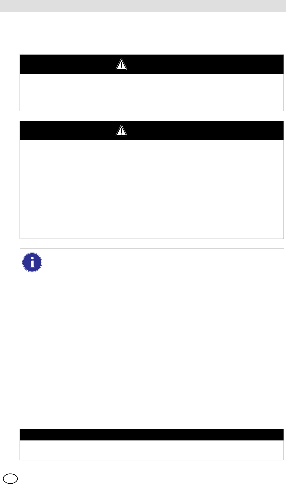
The principal components of the GALAXY GX2 include the Test Stand and optional electronic or
non-electronic Cylinder Holder, Multi-Unit Charger, and Receipt/ Sticker Printer. These compo-
nents [ Fig. 1] are designed to be attached (excluding the printer), to avoid accidental separation
during operation.
Fig. 1 The GALAXY GX2 Automated Test System
MSA AUER
MSA
Introduction
GALAXY GX2 9
US
The Test Stand is a standalone unit that can accommodate one gas detector of the ALTAIR family.
However, each Test Stand contains the plumbing and electronic ports to simultaneously connect
a total of 10 Test Stands and four Cylinder Holders (electronic or non-electronic).
For applications where multiple Cylinder Holders are connected, the Test Stand Expanded Sole-
noid option must be ordered. This option allows the Test Stand to open and close up to four Cyl-
inder Holder valves for gas detectors that may require multiple cylinders for test purposes. For
example, an ALTAIR 5/5X with the standard 4 sensors plus a toxic sensor likely requires two gas
cylinders.
The electronic Cylinder Holder is designed to read a Radio Frequency Identification (RFID) tag
embedded in a plastic ring on MSA test gas cylinders. The RFID tag contains cylinder parameters
that are necessary for successful calibration operations, providing the customer with an excep-
tionally easy setup experience. Gas cylinder information is automatically populated without user
intervention when using the RFID-tagged gas cylinders.
If MSA test gas cylinders are not used, the non-electronic version of the Cylinder Holder is avail-
able. This configuration [ Fig. 2] requires the user to manually enter cylinder parameters.
Fig. 2 Non-electronic Cylinder Holder and Test Stand.
A USB port is provided on the Test Stand that may be used with the Digital Secure USB key to
change instrument settings via the touch screen. This function allows for convenient fleet
management capabilities. The port may also be used for an optional Receipt/ Sticker Printer, to
print calibration/bump stickers or paper receipts after an instrument test.
The primary functions of the Test Stand are to calibrate and bump the ALTAIR family of gas de-
tectors. For a detailed definition of these processes, please refer to:
http://www.safetyequipment.org/userfiles/File/calibration_statement-2010-Mar4.pdf
In the following sections of this manual the user will learn how to install the GALAXY GX2
Automated Test System, set up its functionality, and perform instrument tests. The hardware, soft-

GALAXY GX2
10
Introduction MSA
US
ware, and configuration options anticipate the user's needs and provide superb efficiency in this
next generation Automated Test System.
GALAXY GX2 System Features and Options
The GALAXY GX2 automatically identifies the type of gas detector inserted into the Test Stand.
Based on user-defined settings, the Test Stand then performs bump tests and/or calibrates the
instrument. The data collected from each test event is stored to a memory card [ chapter 2.2]
and/or optional MSA Link™ Pro software application for data analysis (refer to the MSA Link Pro
end-user manual).
2.1 Power Supply
The Test Stand supplies power to the attached electronic Cylinder Holders. The Test Stand and
Multi-Unit charger are powered individually by one of the following methods:
-Power Module: Input power requirements: 100 - 240 VAC, 47 - 63 Hz
(Several different prong types are available for world-wide AC sockets).
-Optional Vehicle Module 12/24 VDC (For use in a cigarette lighter socket).
2.2 The Test Stand
The Test Stand performs the following functions:
-Bump or calibration testing per user setup.
-Records test results to the optional memory card and to an optional networked PC interface.
-Sends gas detector Instrument Periodic and/or Session datalogs to a networked PC interface.
-Provides optional instrument charging capability.
-USB key allows gas detector settings to be changed securely, with the touch of the Test Stand
screen.
-Permits printing of test results to an instrument sticker or receipt, with the optional Receipt/
Sticker Printer.
-Sends e-mail notification of system alerts per user setup.
An LED indicator shows the status of the Test Stand:
-Green light indicates that the Test Stand hardware and software are fully functional.
-Blinking green light indicates that the Test Stand is performing the user specified test or data-
log download.
-Blinking yellow light indicates that the Test Stand is in error and cannot be used for gas detec-
tor testing. Diagnostic information is available as described on the "GX2 Status" screen on the
Test Stand and in the Troubleshooting section of this manual [ chapter 6].
-Red light indicates that the last calibration or bump test failed.
NOTICE
Use of a power supply not specified by MSA will void the instrument warranty and could cause
damage to the GALAXY GX2.
MSA AUER
MSA
Introduction
GALAXY GX2 11
US
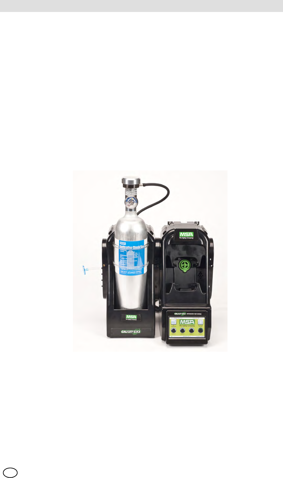
Fig. 3 Test Stand Physical Features
SD or SDHC Memory Card Slot
A memory card port is provided on the Test Stand for calibration and bump record storage. An
SD or SDHC memory card can be purchased from MSA (preferred) or from the following manu-
facturers:
-Kingston
-PNY
-SanDisk
-Lexar
-Wintec
The data on an SD or SDHC memory card is encrypted for use with MSA Link™ or the
MSA Link Pro application. The type and amount of data recorded to the memory card is contin-
gent on whether the Test Stand is networked.
Test Stand Networked to a PC
When the Test Stand is networked to a PC through the Ethernet port, test records, datalogs, and
settings will be transmitted from the GALAXY GX2 to the PC interface.
If the network connection is lost only calibration and bump records are saved to the memory card.
If the Ethernet connection is restored, the Test Stand will transmit the stored calibration and bump
records from the memory card to the PC interface.
1 Touch Screen Display 4 SD Card Port
2 Status LED 5 USB Port
3 Test Stand to Test Stand connector 6 Gas plugs
1
2
3
4
5
6
The use of MSA Link Pro via a network connection is required to download datalogs
from the instrument. Due to potentially large file sizes datalogs are not saved to the
memory card in the Test Stand.
GALAXY GX2
12
Introduction MSA
US
Test Stand is Stand-Alone
If the GALAXY GX2 is not networked to a PC interface the memory card will save each calibration
and bump test record. Incomplete records will not be saved. If networked and e-mail alerts are
configured, the Test Stand will generate an email alert once the memory card reaches 90% and
again at 99% capacity.
Once a memory card reaches full capacity, the Test Stand will be in fault and prohibit any unit from
performing tests in that bank, until corrected. The Test Stand can be configured to erase the
memory card, or the user can insert a replacement.
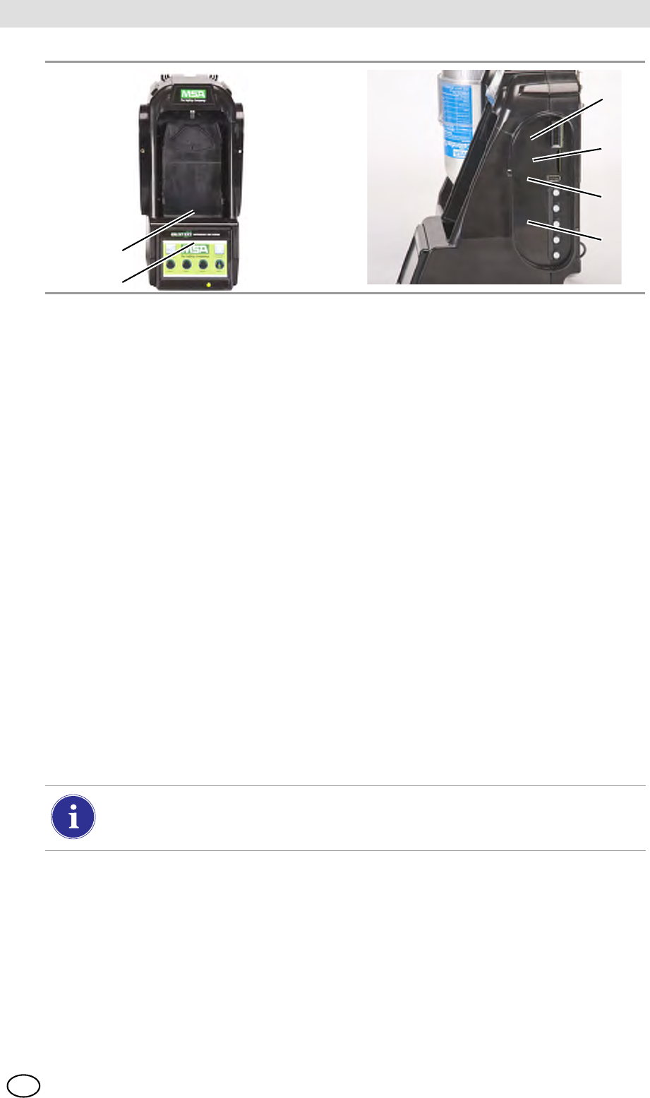
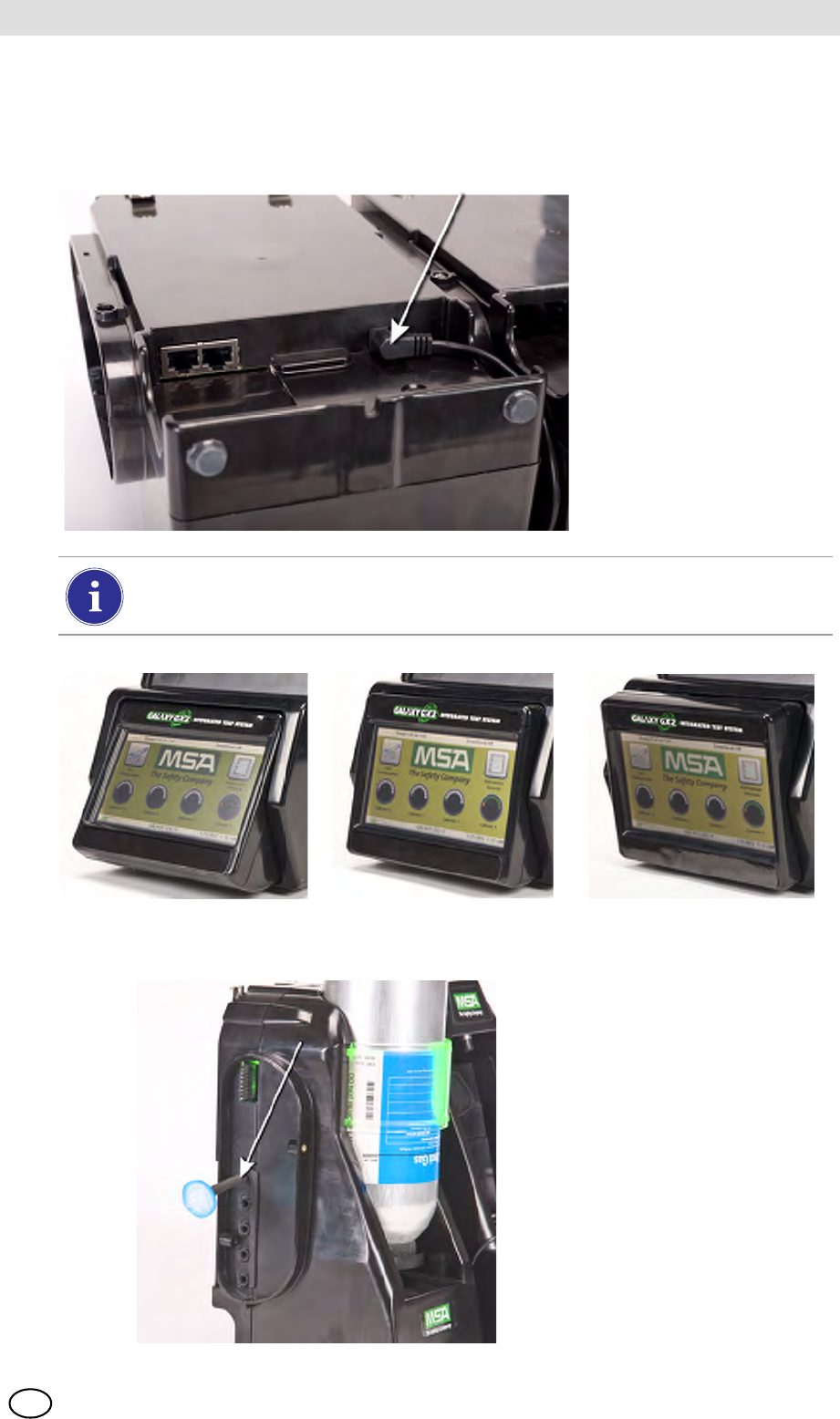
An optional end cap [ Fig. 4] can be placed over the port to protect the memory card and all
external connections.
Fig. 4 Optional End Cap
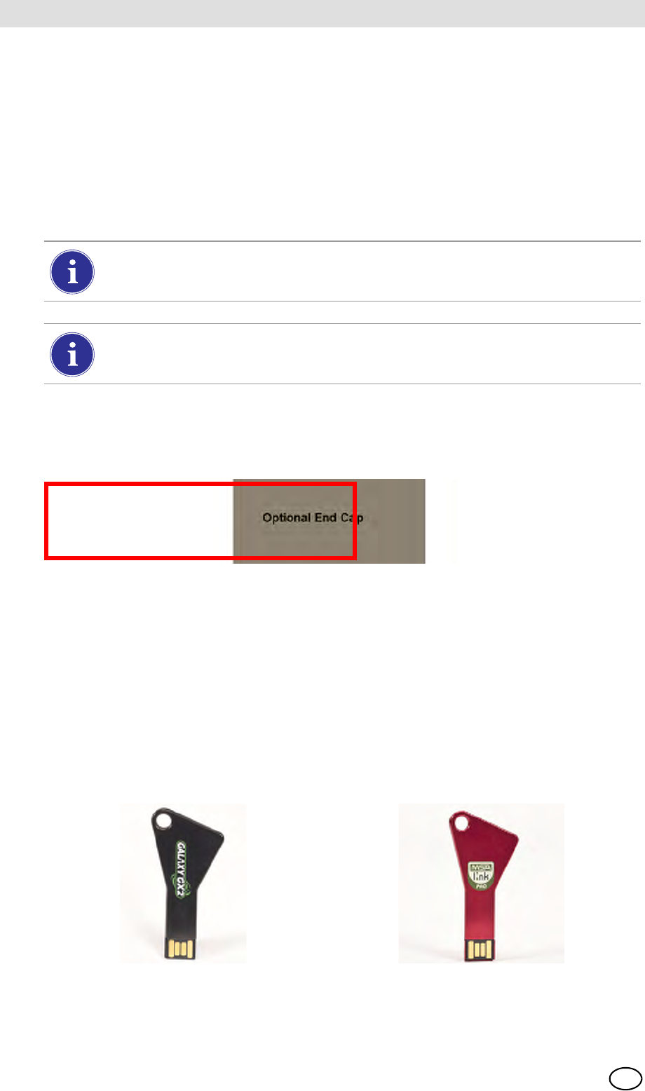
USB Drives
Two optional USB Keys [ Fig. 5] are available for purchase with the GALAXY GX2
Automated Test System:
-Digital Secure USB Key: This black key is inserted in the USB port on the Test Stand in order
to change gas detector settings. The key ensures only authorized users can change settings
on ALTAIR gas detectors; a security step in addition to the four-digit password.
-MSA Link Pro Key: This red key is used to enable the MSA Link Pro application on a single
PC. More information about this key can be found in the software product end-user manual.
Fig. 5 Digital Secure Key and MSA Link Pro Key
The memory card should only be removed when no test activity is occurring. Events that
occur while no memory card is installed will not be stored in the Test Stand.
If no memory card is used, only the most recent bump or calibration record is stored to
the Test Stand internal memory.
DUMMY!
Awaiting final plastic
- mid March
MSA AUER
MSA
Introduction
GALAXY GX2 13
US
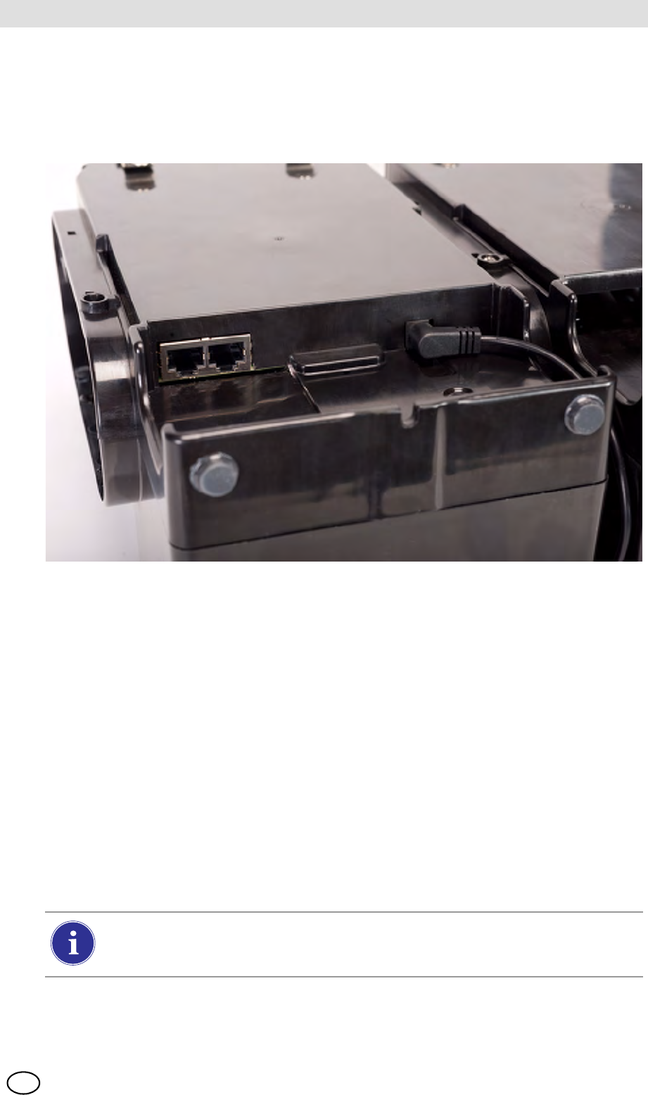
2.3 Ethernet Interface
Two Ethernet Interfaces are provided on the rear of the GALAXY GX2 [ Fig. 6]. The ports allow
for the connection and communication distribution between multiple Test Stands. If networking to
a computer, one USB port on the Master Test Stand is used to communicate with the
MSA Link Pro software application.
Fig. 6 Test Stand Ethernet jacks
2.4 Software Options
The GALAXY GX2 functions as a standalone system, but the optional MSA Link Pro software
application can be used to network the Test Stand to a PC through an Ethernet cable. This appli-
cation provides a best-in-class user interface and data analysis toolset to quickly identify issues
or concerns that require user action.
MSA Link Pro provides the user:
-Database storage of instrument Periodic and Session datalogs.
-Automatic or customized reports from the collected data.
-Single glance notification of instruments that are overdue for calibration or bump test.
-Email notifications of GALAXY GX2 and instrument warnings and error messages.
-Single setting configuration of all GALAXY GX2 units in a bank.
No need to individually configure each Test Stand.
To learn more about installing and using MSA Link Pro, refer to the software product end-user
manual.
Users may use the free MSA Link software application and an IR dongle
[ chapter 7.2] to communicate directly with their gas detector. MSA Link allows a user
to upload and download instrument settings, and download datalogs.
GALAXY GX2
14
Introduction MSA
US
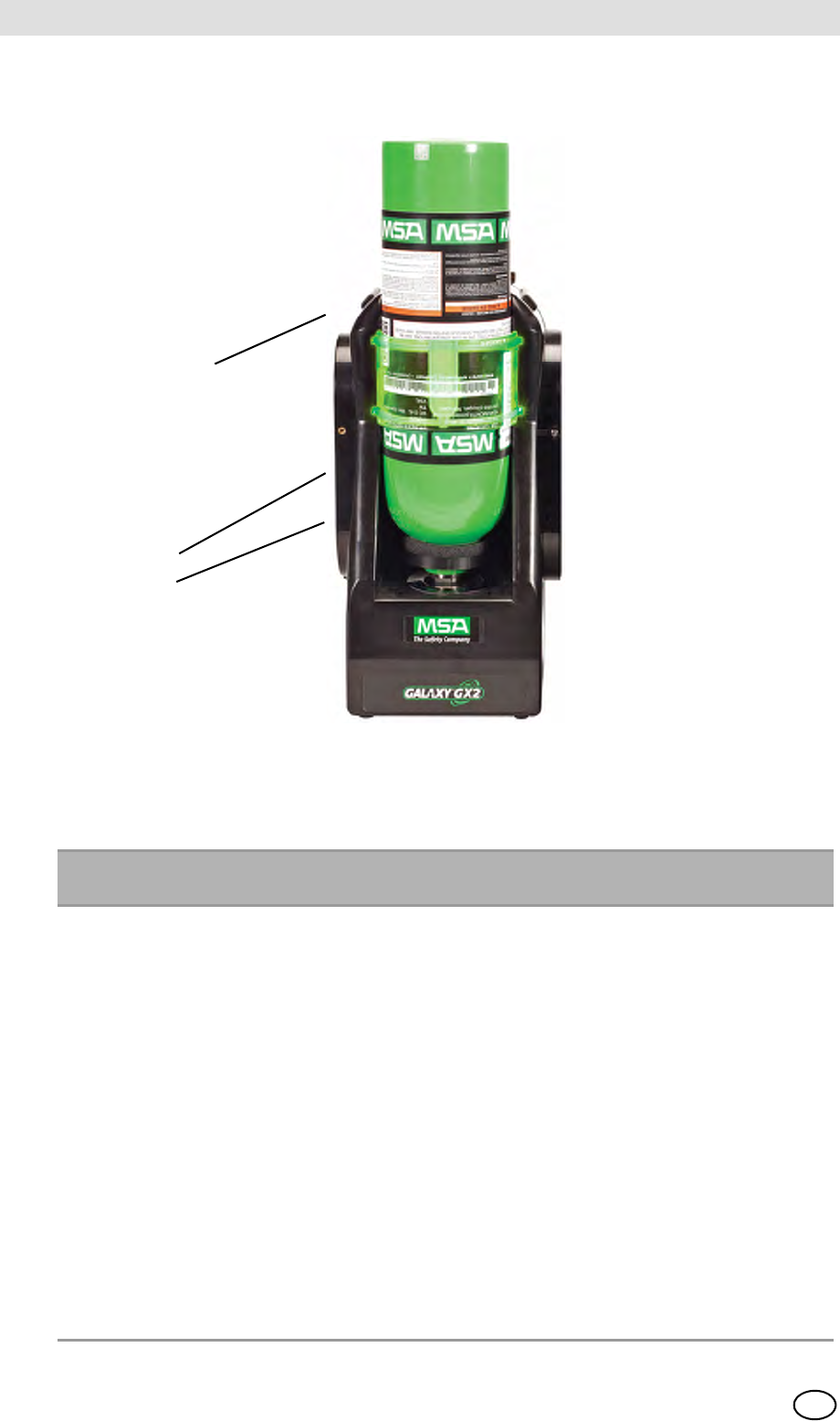
2.5 Cylinder Holder (electronic)
The electronic Cylinder Holder can accommodate one test gas cylinder and includes:
Fig. 7 Cylinder Holder Physical Features
1 Light Band 2 RFID Tag 3 Internal Pressure Regulator
& Sensor
Multi-Color Light Band RFID Tag Gas
Identification Pressure Regulator & Sensor
Indicates gas bottle functionality.
-Green indicates a bottle is
completely functional, and gas
parameters are within pressure
and expiration date limits.
-Yellow indicates low calibration
gas, or gas is nearing its expira-
tion date.
-A blinking yellow light band indi-
cates a hardware problem with
the cylinder holder.
-Red indicates an empty calibra-
tion gas bottle, or that gas has
expired.
Reads the RFID tag of
the MSA test gas cylin-
der and transmits:
-the gas type
-gas concentration
-expiration date
-lot number
-cylinder part number
to the Test Stand. The
RFID tag is only availa-
ble on MSA-branded test
gas cylinders shown in
the Maintenance section
[ chapter 7].
Reads the pressure of the gas
cylinder and transmits that
information to the Test Stand.
-When gas pressure drops to
approximately 99 psi
(6.89 bar) a warning will
display and the display
numbers appear yellow.
-Once pressure drops to ap-
proximately 49 psi (3.45 bar)
the display numbers appear
red.
-Once pressure drops to less
than 5 psi (0.34 bar) the
Test Stand will prohibit test-
ing with that cylinder.
1
2
3
MSA AUER
MSA
Introduction
GALAXY GX2 15
US
2.6 Optional Printer
The Printer can print calibration and bump result receipts and calibrations stickers for gas detec-
tors [ Fig. 7]. The Receipt/ Sticker Printer uses a USB cable to connect to the port of the farthest
right Test Stand [ Fig. 3].
Labels are available in two formats [ chapter 7.2]:
-Format #1: Calibration Sticker only (2 cm x 2 cm square label).
-Format #2; Receipt and Sticker combined.
Fig. 8 Optional Printer
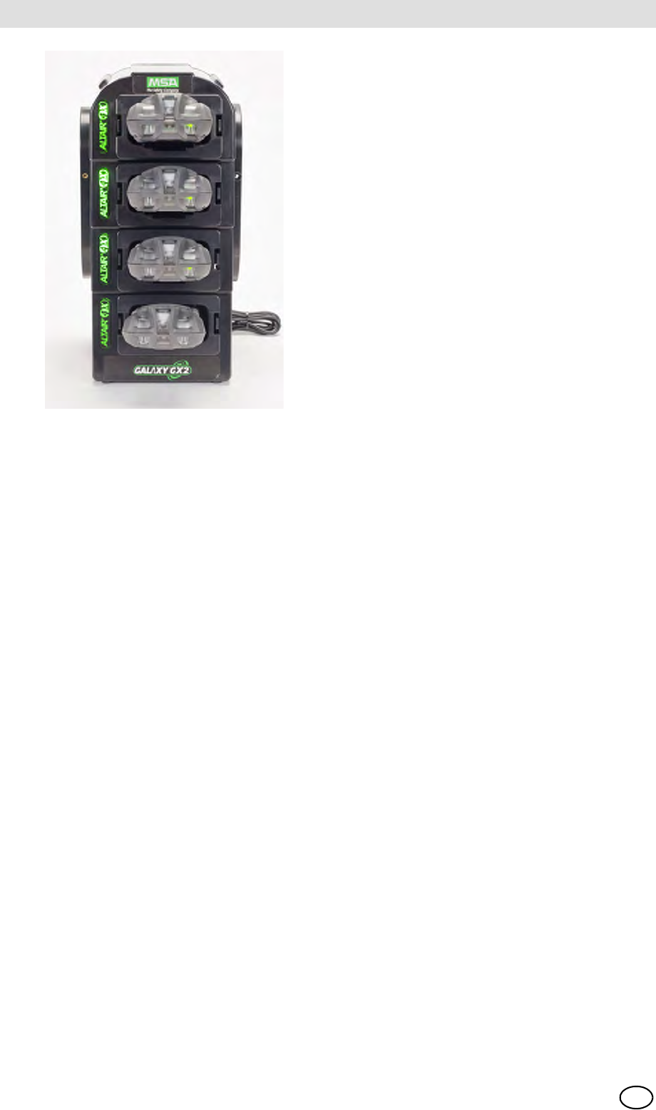
2.7 Optional Multi-Unit Charger
There are two configurations of the optional Multi-Unit Charger (MUC). The ALTAIR 4/4X MUC
can simultaneously charge up to four ALTAIR 4/4X gas detectors. Similarly the ALTAIR 5/5X MUC
can charge four 5/5X gas detectors. Each Multi-Unit Charger contains its own power supply and
does not connect electrically to the Test Stand. The housing is designed to physically connect to
each other, whether bench-top or wall-mounted (if desired).
The light indicators on the Multi-Unit Charger are defined as follows:
-Red indicates that the unit is charging
-Green indicates that the unit is fully charged or no unit is inserted.
There can be as much as a 10 minute window between when the instrument battery indicator
shows charged and the Multi-Unit charger status indicator changes. The instrument indicator is
the most accurate and will indicate the true charge state of the battery.
DU
MM
Verify the Multi-Unit Charger indicator lights red when an instrument is inserted. A fully
charged instrument will momentarily flash red and the indicator will light green. If the red
light does not engage the instrument may not be seated properly on the charging prong.
Instruments whose battery is completely discharged will be need to trickle-charge
prior to normal charging operations. Such instruments will show a green LED during the
trickle-charge period until normal charging is initiated, at which time the red LED will be
active.
GALAXY GX2
16
Introduction MSA
US
Fig. 9 Multi-Unit Charger (Altair 4/4X and 5/5X only)
2.8 Special Conditions for Use with Reactive Gases
If using a Test Stand and Cylinder Holder for calibrating or bump testing a gas Detector config-
ured with a chlorine or ammonia sensor:
-Place the chlorine or ammonia gas cylinder in the Cylinder Holder closest to the Test Stand.
-Only one reactive gas Test Stand is allowed in a bank.
-If connecting other Test Stands to the right of the reactive stand, plug the reactive gas outlet
port with a white gas plug before mating the next Test Stand. Otherwise, inaccurate calibration
could result on the reactive sensor.
-Before the first use with reactive toxic gas, condition the regulator and Test Stand with the gas,
by running the calibration twice in sequence. If using chlorine, perform this procedure daily be-
fore use.
If not using GALAXY GX2 Cylinder Holders:
-Use a dedicated pressure regulator on the reactive toxic gas cylinder (for chlorine or ammonia,
use P/N 10034391). Label the pressure regulator "FOR CHLORINE USE ONLY" or
"FOR AMMONIA USE ONLY", as applicable (label stickers are provided with regulator).
-Use the shortest possible tubing running from the reactive toxic gas pressure regulator to the
Test Stand's "CYLINDER 1" port.
-Before the first use with reactive toxic gas, condition the regulator and Test Stand with the
gas by running the calibration twice sequentially; for chlorine, perform this procedure daily be-
fore use.
-Many gases have a cross-sensitivity to other gases. Ensure that test cylinder gases do not
contain other interfering gases.
Do not use the GALAXY GX2 to calibrate or bump a gas detector with a chlorine dioxide (ClO2)
sensor.
MSA AUER
MSA
Installation
GALAXY GX2 17
US
3 Installation
The GALAXY GX2 is a simple to install system that can be desktop or wall mounted. Setup re-
quires simple tools and just a few minutes of time.
Carton Contents
The GALAXY GX2 system will be shipped with the following:
-Test Stand (including gas plugs, barbs and fresh air filter)
-Power Supply (if ordered)
-Spare Parts Kit (gas tubing barbs and plugs)
-Ethernet Cable (short cable for connection between Test Stands)
-Product CD
-Quick Start Guide
-Screen Protector (installed on the display screen)
Tools Needed
-Phillips head (cross-head) screwdriver.
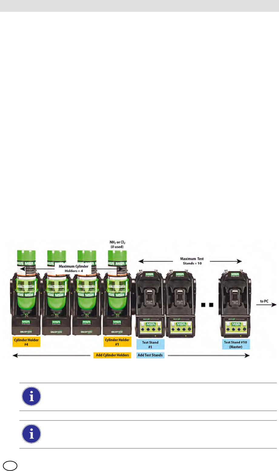
As stated in the Introduction, the GALAXY GX2 is designed for the connection of up to 10 Test
Stands and four Cylinder Holders [ Fig. 10]. Test Stands must be assembled sequentially on the
right-hand side of the first. Cylinder Holder(s) must be installed on the left-hand side of the first
Test Stand for best gas flow into all Test Stands.
Fig. 10 Test Stands and Cylinder Holders properly installed in a bank
Test gas cylinders containing Chlorine or Ammonia must be installed according to the
directions in the Special Conditions for Use with Reactive Gases section
[ chapter 2.8].
When installing the GALAXY GX2, please consider the environmental needs of your
facility. If the customer desires, the GALAXY GX2 can be used in a ventilated area to
assist in disbursing the test gas exhaust.
GALAXY GX2
18
Installation MSA
US
This manual provides steps for desktop and wall mounting. The following sections describe the
proper installation for various GALAXY GX2 configurations:
-Connect Units in a Bank (Test Stands and Cylinder Holders) [ chapter 3.1]
-Connect a Test Gas Source Without a Cylinder Holder (optional) [ chapter 3.2]
-Network Test Stands (optional) [ chapter 3.3]
-Removing Gas Seal for Certain ALTAIR and ALTAIR Pro Instruments [ chapter 3.4]
-Desktop Mounting [ chapter 3.5]
-Wall Mounting [ chapter 3.6]
-SD or SDHC Memory Card Option [ chapter 3.7]
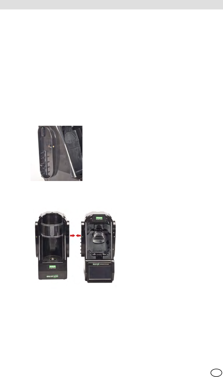
3.1 Connect Units in a Bank
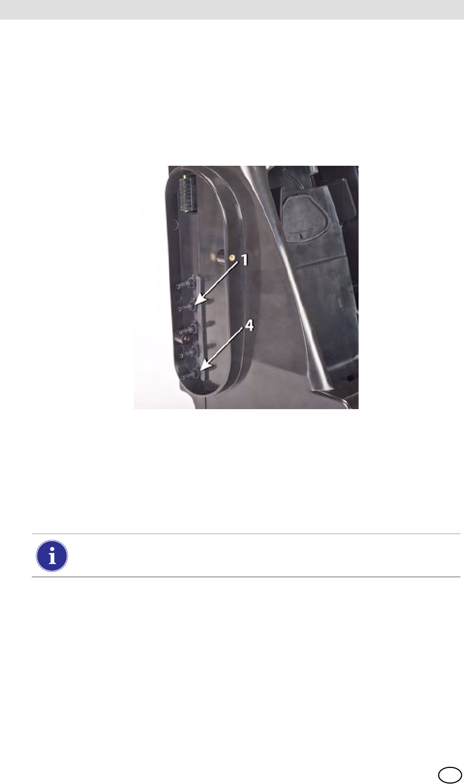
(1) On the left-hand side of the Test Stand, ensure all five barb fittings are in place and straight-
ened before connecting a Cylinder Holder or another Test Stand.
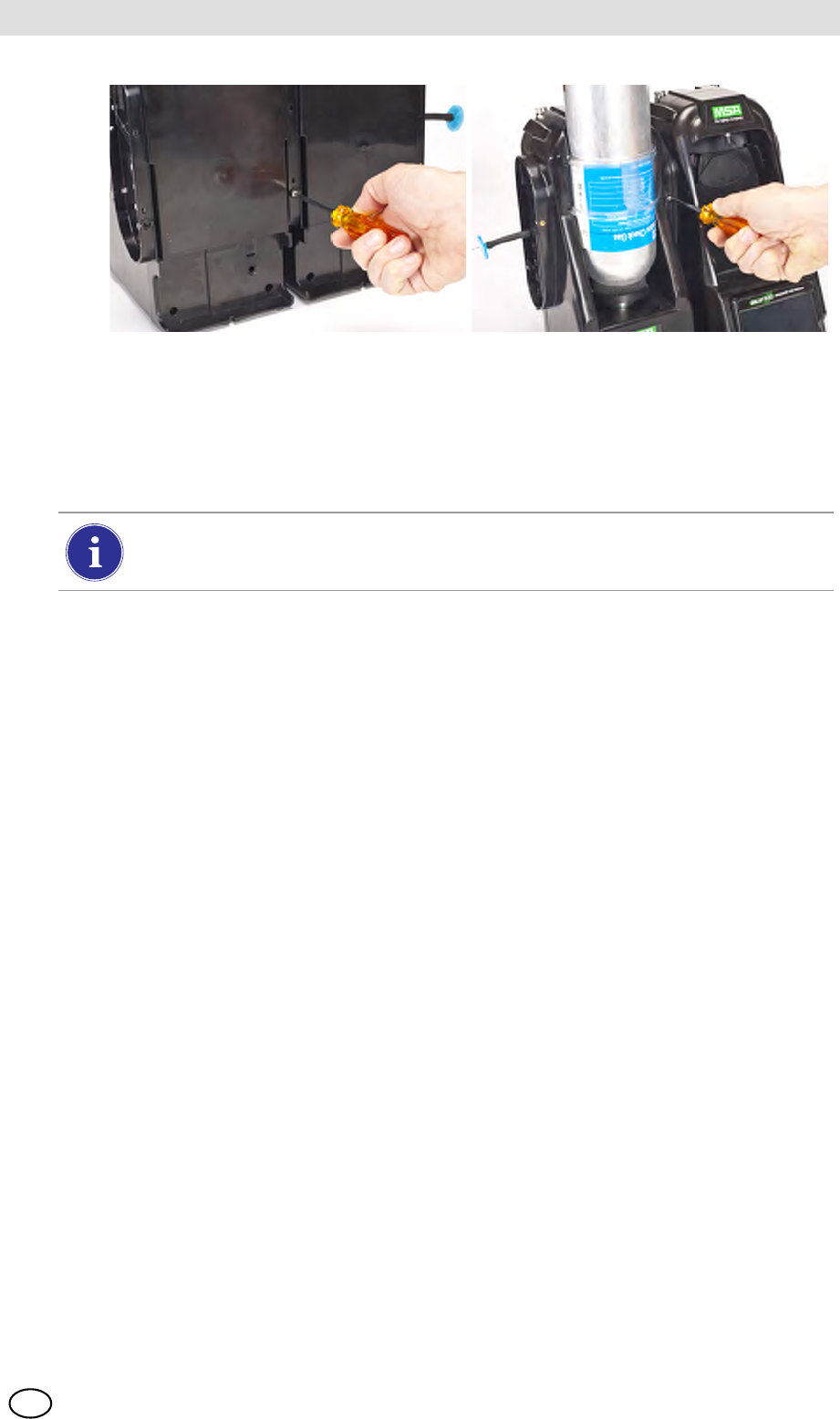
(2) Press the two units together until the barb fittings are fully inserted and the screw holes in
the flange align.
(3) Insert one of the supplied screws into the front and two screws into the back of the flange.
MSA AUER
MSA
Installation
GALAXY GX2 19
US
(4) If connecting multiple Test Stands, remove the white gas plugs [ Fig. 3] from all units ex-
cept the farthest right Test Stand. If using ammonia or chlorine test gas, read the restriction
found under chapter 2.8 “Special Conditions for Use with Reactive Gases” regarding the
white plugs.
(5) Continue adding Test Stands to the right and Cylinder Holders to the left [ Fig. 10].
3.2 Connect a Test Gas Source Without a Cylinder Holder
If high-pressure, high-capacity test gas cylinders are preferred, an optional demand regulator
(p\n 710289) is available for cylinders with pressure less than (<) 3000 psi. Testing from an inde-
pendent gas source will require additional setup effort, as described in the Cylinder Configuration
section [ chapter 4.7].
(1) On the left-hand side of the Test Stand, ensure all five barb fittings are in place and straight-
ened.
(2) Place the user-supplied regulator onto the gas cylinder and secure a length of tubing onto its
outlet.
(3) Securely fit the end of the tubing over the appropriate barb fitting on the GALAXY GX2.
3.3 Network Test Stands
Test Stands that are banked together should be connected through the provided Ethernet cable.
The Master Test Stand is the one located on the furthest right of the bank.
(1) Insert the short Ethernet cable into the left side jack of each Test Stand (1) and connect it to
the right side jack of the neighboring unit (2) [ Fig. 11].
ZOne interconnect Ethernet cable is included with each Test Stand.
When connecting two or more Test Stands ensure the white plugs are secured on the
right side of the farthest right unit to prevent gas leakage.
GALAXY GX2
20
Installation MSA
US
Fig. 11 Test Stand Ethernet connections
(2) If connecting the bank to a computer with the MSA Link Pro software, use a customer-
supplied ethernet cable and connect via the Master Test Stand ethernet port #1 shown
above.
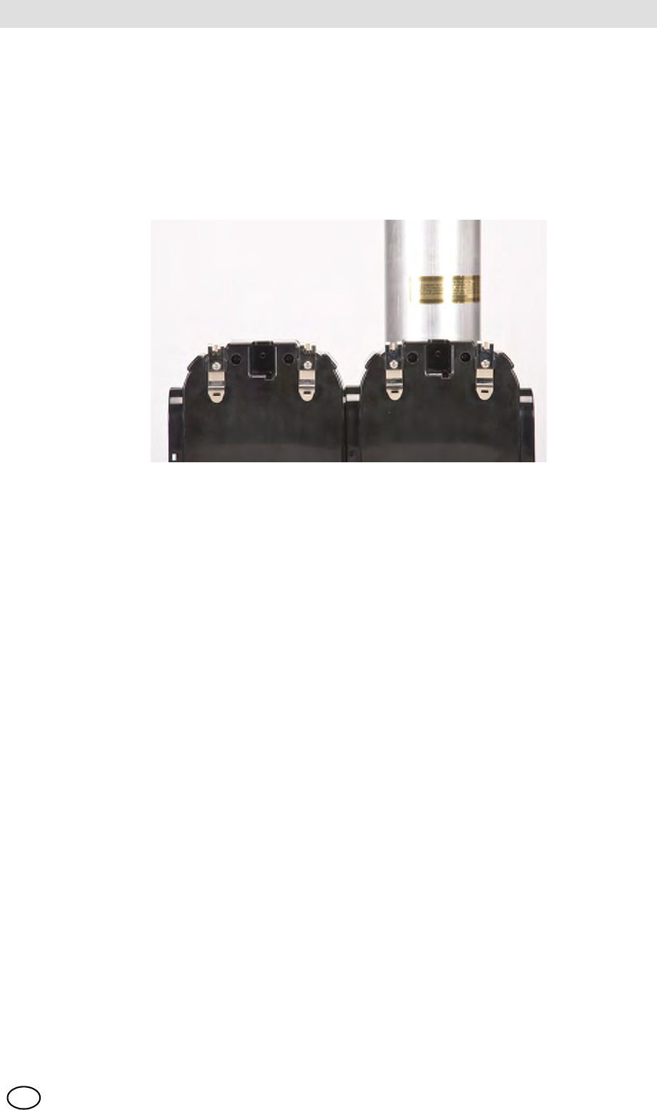
3.4 Removing Gas Seal for Certain ALTAIR and ALTAIR Pro Instruments
All ALTAIR/ALTAIR Pro Test Stands will be shipped with a black rubber base seal and a green
rubber gas seal. The green seal is used only for ALTAIR H2S and ALTAIR CO instruments.
The seal should be removed and stored for ALTAIR O2 and all ALTAIR Pro instruments.
Fig. 12 Altair and Altair Pro Inlet Seals
1 MSA Link Pro port 2 Test Stand to Test Stand port
2
1
DUMMY!
Will be replacing this
photo - mid March
MSA AUER
MSA
Installation
GALAXY GX2 21
US
3.5 Desktop Mounting
(1) Place the GALAXY GX2 on a flat, stable surface.
(2) Insert the power supply into the GX2 power jack [see chapter 4.1 for first-time power up ini-
tialization].
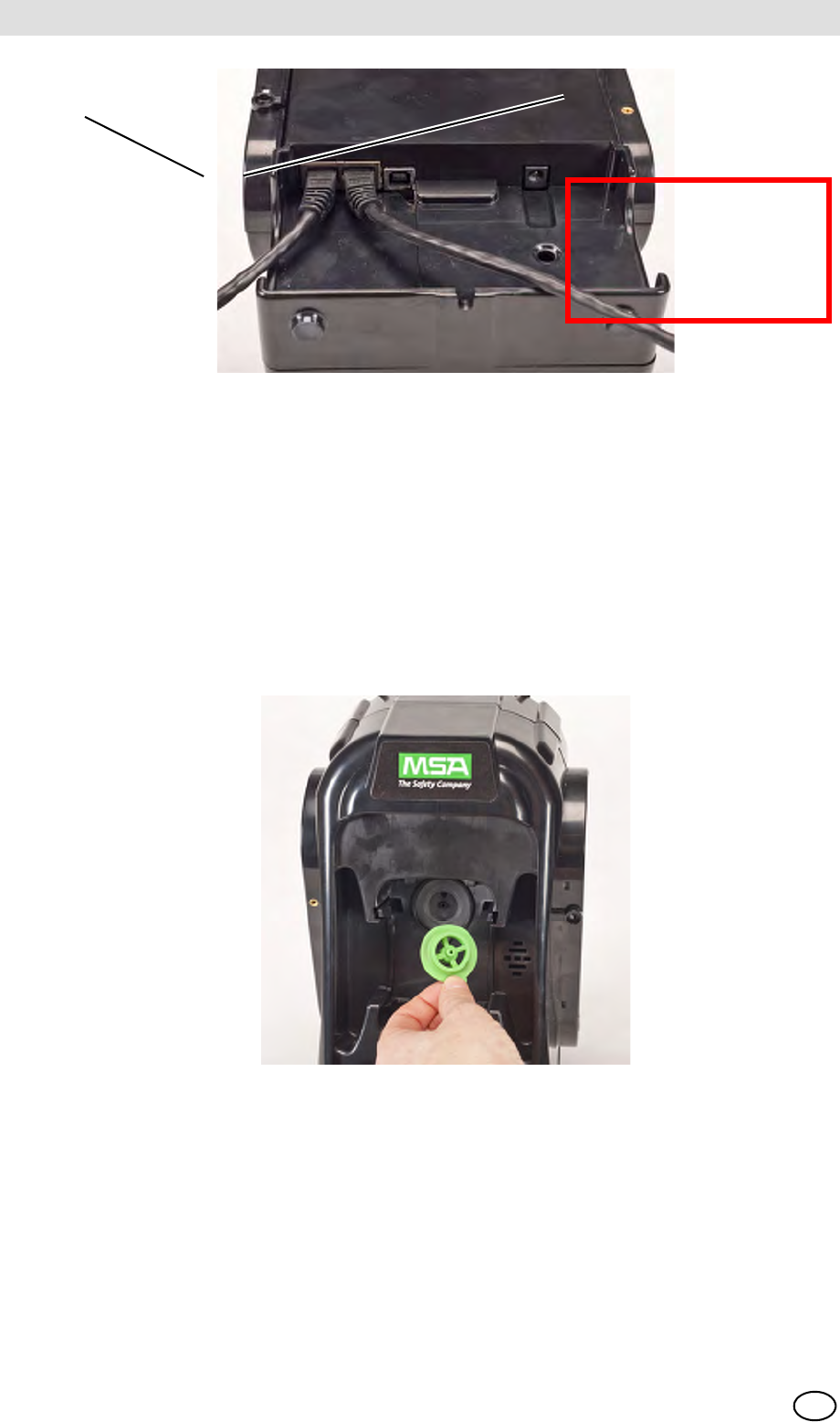
(3) If using MSA Cylinder Holders, the left most Cylinder Holder should have a fresh air filter
attached to the top port.
The Test Stand display pivots for ease of viewing.
GALAXY GX2
22
Installation MSA
US
(4) If not using MSA Cylinder Holders, the left most Test Stand should have a fresh air filter
attached to the top port.
(5) Ensure the white plugs are inserted into the five gas connection fittings on the right side of
the farthest right test stand.
MSA AUER
MSA
Installation
GALAXY GX2 23
US
3.6 Wall Mounting
When wall mounting the Test Stand (and applicable Cylinder Holder), MSA recommends steps
1-5 from the Desktop Mounting section [ chapter 3.5] above be completed prior to installing on
the Din Rail. For a large configuration of Test Stands and Cylinder Holders, MSA recommends
several people be used for installing or uninstalling from the DIN rail.
(1) Complete steps 1-5.
(2) Secure the optional DIN rail Clips to the rear of the GALAXY GX2, using the included screws.
(3) Mount the DIN rail (Type Omega) to the wall by securing it with wall anchors or other suitable
fasteners.
(4) Align the DIN rail clips over the wall-mounted DIN rail and snap into place.
(5) To remove from the DIN rail, grasp the back of the units and pull outward.
GALAXY GX2
24
Installation MSA
US
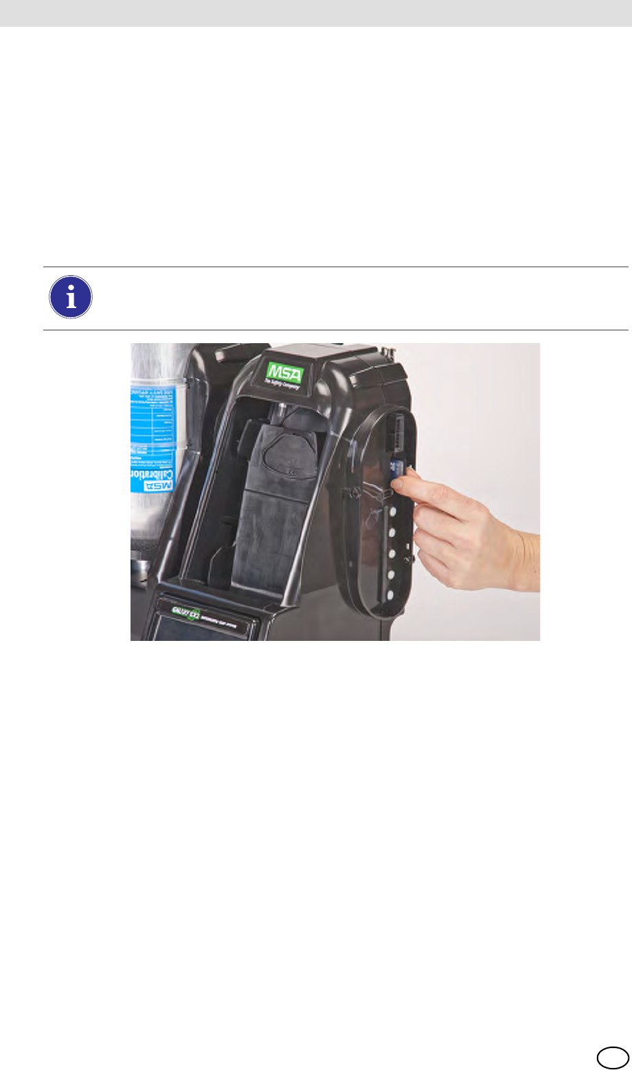
3.7 SD or SDHC Memory Card Option
The Test Stand can accommodate an SD or SDHC memory card, inserted in the port on the right
hand side of the farthest right Test Stand. Only one memory card can be used in a bank.
To install the memory card:
(1) Ensure that memory card is not write-protected or locked.
(2) Insert the memory card into the port, located on the right side of the Test Stand [ Fig. 13].
(3) Place the optional end cap over the port to protect the memory card.
(4) To remove the memory card push the card to eject it from the port.
Fig. 13 SD or SDHC Memory Card Installation
The memory card should not be removed when testing or datalog downloads are in
process. The Test Stand will not store events that occur while a memory card is re-
moved.
MSA AUER
MSA
Setting Up the GALAXY GX2
GALAXY GX2 25
US
4 Setting Up the GALAXY GX2
The GALAXY GX2 Automated Test System is shipped with the most common default options and
therefore requires minimal set up. A table of all default settings is provided in the Galaxy GX2 De-
fault Parameters section [ chapter 9] at the end of this manual. Configuration settings are de-
scribed in this chapter and can be changed to meet your individual needs via the touch screen
display.
The touch screen is intended for interaction with the user's bare finger. Gloves may interfere with
screen operation. The attached touch screen protector inhibits damage and should not be re-
moved. Replacement screen protectors can be purchased from MSA.
4.1 Initial Setup
The first time the Test Stand is powered on an initial set of screens will appear for system config-
uration. The GALAXY GX2 logo momentarily displays and then the unit's version number. This is
followed by the first of three required screens.
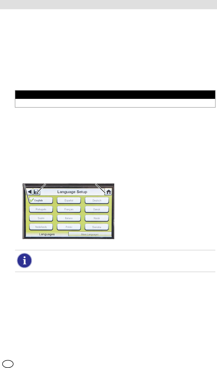
Language Setup
The Language Setup screen automatically displays.
NOTICE
Use of sharp objects on the touch screen could cause damage.
(1) Select your language from the list.
ZThe language zone selection de-
termines the date format, either
MM/DD/YYYY or DD/MM/YYYY.
(2) Select Save.
(3) Select Home.
123
Changes must be saved on all screens by selecting the Save icon (shown above). If the
user selects the Back Arrow (W) without saving, a prompt will display. Select Yes to
save or No to discard changes.

GALAXY GX2
26
Setting Up the GALAXY GX2 MSA
US
Set Time and Date
There are 3 tabs at the bottom of the screen - Date, Time Zone and Time. The user will need to
configure each tab. The Date Setup screen automatically displays.
(1) Enter the current month, day and
year.
The time setting is used on all calibration and bump test records.
Test Stand time and date must be maintained for accurate record keeping.
If the Test Stand is networked to a PC via the MSA Link Pro software application,
the time is automatically synchronized to the PC. The gas detector is automatically syn-
chronized to the Test Stand each time it is inserted.
(2) Select the Time Zone tab and then
select your time zone.
ZThe time zone application is de-
fined by the standard Microsoft®
operating system.
Select Daylight Savings Time to enable automatic time adjustment when
Daylight Savings Time occurs.
(3) Select the Time tab and enter the
current time.
(4) Select Save.
(5) Select Home.
The time and date is used for calibration and bump recordkeeping of the instrument.
24-hour or 12-hour time may be chosen.
MSA AUER
MSA
Setting Up the GALAXY GX2
GALAXY GX2 27
US
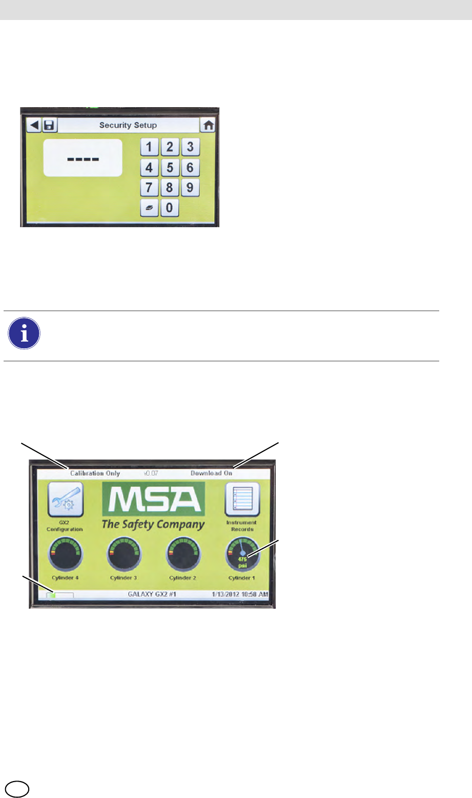
4.2 Security Setup
The Security Setup is the last screen to automatically display. Setting a numeric password
prohibits unauthorized changes to the GALAXY GX2.
4.3 Home Screen
The Home Screen displays the relevant parameters for the Test Stand and electronic Cylinder
Holders.
Fig. 14 Test Stand Home Screen
If no password is desired, enter "0000" to
disable the password feature. The Test
Stand is shipped with the password dis-
abled.
(1) Enter a four-digit password for the
GALAXY GX2.
(2) Select Save.
Retain a copy of the password for
your records.
(3) Select Home.
(4) The GALAXY GX2 Home screen
displays [ Fig. 14].
To change the password, return to the Security Setup screen, enter a new password
and select Save.
If your password has been misplaced, call MSA Customer Service for reset instructions.
1 Test Mode 3 Gas Cylinder Pressure Gauge
2 Gas Detector Datalog Download Mode 4 Gas Detector Charging status
2
3
1
4
GALAXY GX2
28
Setting Up the GALAXY GX2 MSA
US
Test Mode
Bump Only, Calibration Only, or Bump/Cal on Fail. The mode is selected in the Test Setup section
[ chapter 4.5] of this manual.
Gas Detector Datalog Download
On or Off. This setting is described in the GALAXY GX2 Setup, Datalog section [ chapter 4.5]
of this manual.
Pressure Gauges
Display test gas cylinder pressure from the electronic Cylinder Holder only. Selecting a
pressure gauge displays gas cylinder details.
Charging Status
If gas detector charging is installed the battery symbol will display in the lower left corner of the
screen. When the gas detector is charging, the battery symbol will cycle. When the instrument is
either fully charged or not present, the battery symbol will be solid green.
There can be as much as a 10 minute window between when the instrument battery indicator
shows charged and the Test Stand battery symbol shows solid green. The instrument indicator is
the most accurate and will indicate the true charge state of the battery.
GX2 Configuration
Provides access to GALAXY GX2 settings. (Password screen will display if configured.) Steps are
found under GALAXY GX2 Setup section [ chapter 4.2] of this manual.
MSA AUER
MSA
Setting Up the GALAXY GX2
GALAXY GX2 29
US
Instrument Records
Provides the most recent calibration and/or bump record for each instrument in the Test Stand
bank. This button is only active on the Master Test Stand. All other Test Stands will report their
data to the Master Test Stand for display.
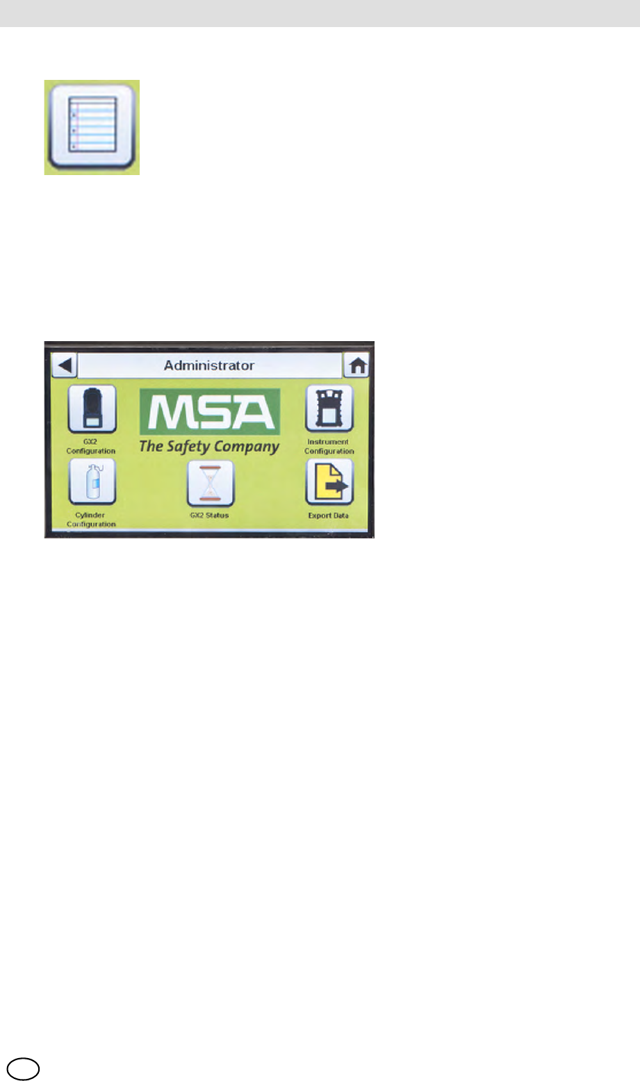
4.4 General Setup
The following settings can be changed from their default values after entering the password.
Select GX2 Configuration from the Home screen. The Administrator screen displays.
Fig. 15 Administrator screen
The Administrator screen provides configuration options for the Test Stand (1), instrument (2) and
test gas cylinders (3).
The GX2 Status selection (4) provides detailed information about the Test Stand that can be used
to troubleshoot identified errors.
The Export Data selection (5) is used to upload instrument settings to a docked gas detector.
4.5 GX2 Configuration
To configure the settings for the GALAXY GX2 select GX2 Configuration [ Fig. 15] on the
Administrator screen.
1 GX2 configuration for Test Stand [ chapter 4.5] 4 GX2 Status selection
2 Instrument configuration [ chapter 4.6] 5 Export Data selection
3 Test gas cylinder configuration [ chapter 4.7]
GALAXY GX2
30
Setting Up the GALAXY GX2 MSA
US
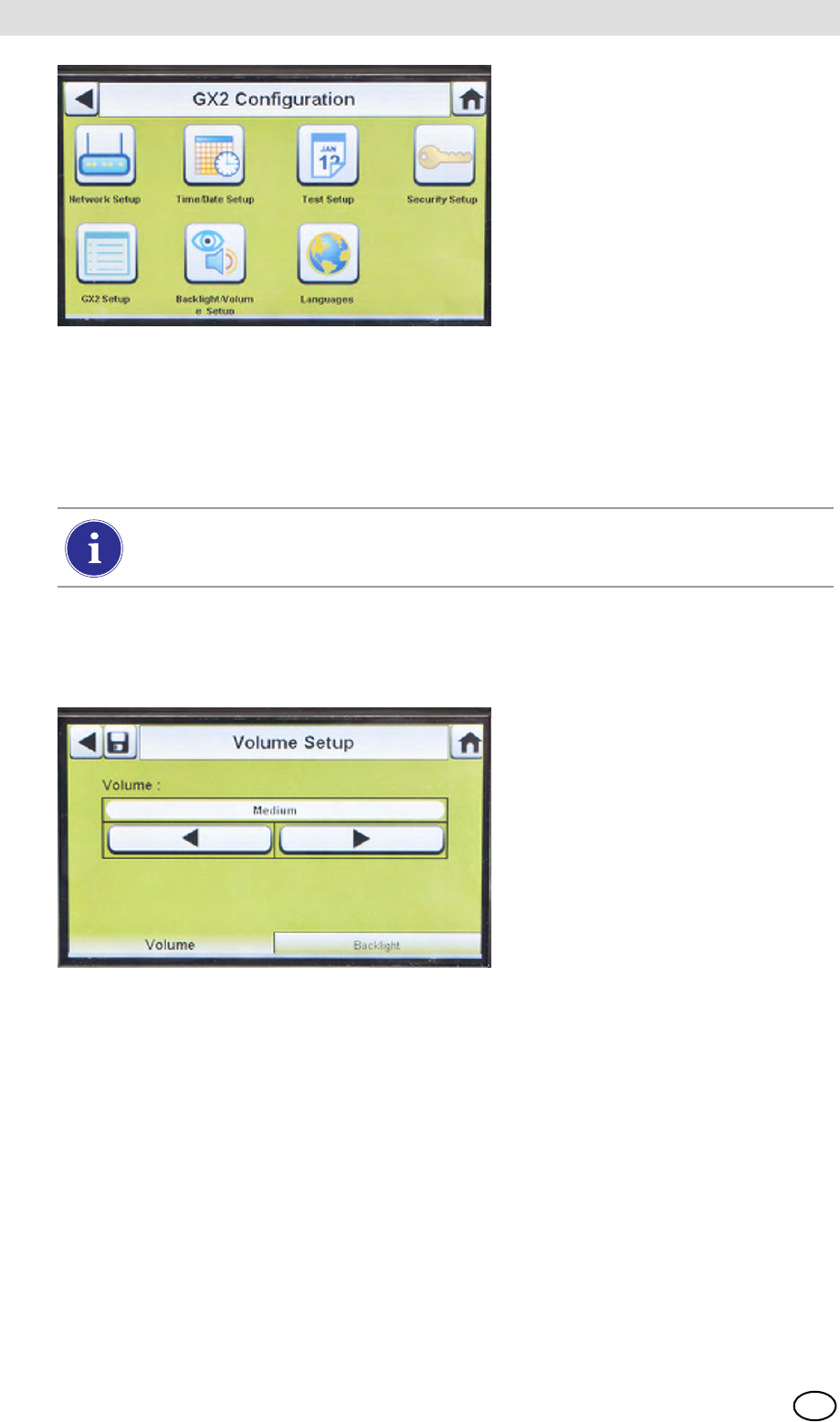
Fig. 16 GX2 Configuration
Backlight/Volume Setup
Select Backlight/Volume Setup on the GALAXY GX2 Configuration screen [ Fig. 16] to access
the Backlight/Volume screens.
Volume Tab
The user can set the volume for audio indicators.
(1) Set the volume by selecting either the left or right arrows on the volume screen.
ZThe default volume level is set to Medium.
(2) Select Save.
Backlight Tab
The user can set the backlight intensity of the display screen.
(1) Set the backlight by selecting either the left or right arrows on the backlight screen.
ZThe default backlight level is set to Medium.
(2) Select Save.
1 Network Setup [ chapter 4.5] 5 GX2 Setup [ chapter 4.5]
2 Time/Date Setup [ chapter 4.1] 6 Backlight/Volume Setup [ chapter 4.5]
3 Test Setup [ chapter 4.5] 7 Languages [ chapter 4.1]
4 Security Setup [ chapter 4.2]
The Time/Date Setup, Security Setup, and Languages Setup have been described in
the Initial Setup section [ chapters 4.1 and 4.2].
MSA AUER
MSA
Setting Up the GALAXY GX2
GALAXY GX2 31
US
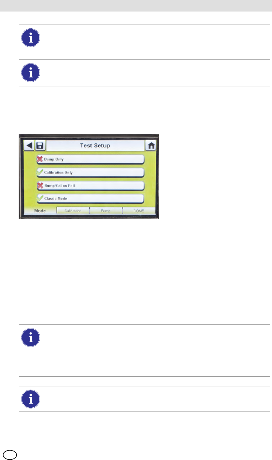
Test Setup
Select Test Setup on the GALAXY GX2 Configuration screen [ Fig. 16] to access the
Test Setup screens. There are 4 tabs that can be selected under Test Setup: Mode, Calibration,
Bump and COMB.
Mode Tab
Select the Mode tab to setup the Test Stand for Bump Only, Calibration Only, Bump/Cal on Fail,
or Classic Mode.
-Bump Only setting bumps an instrument and reports a pass or fail status.
-Calibration Only performs a full calibration on an instrument every time it is docked.
-Bump/Cal on Fail (default setting) will bump an instrument. If it fails the bump, the Test Stand
automatically performs a full calibration.
-Classic Mode (3= enabled) initiates the user-selected test mode each time an instrument is
inserted in the Test Stand. The Classic Mode feature means, "always test".
To return to the GX2 Configuration screen, select the back arrow W on the top left cor-
ner of the screen.
The GALAXY GX2 will reduce the backlight intensity automatically after a period of
inactivity. Either select a button or insert an instrument to return the intensity to the user
selected level.
Disabling Classic Mode (2 = disabled) sets the Test Stand to calibrate or bump an in-
strument only if the due date approaches. The Test Stand will read the last calibration
(or bump) date and add the GX2 Calibration (or Bump) Interval. If the setting is within
5-days of the calibration (or bump) due date, the Test Stand will begin the test. If the
calibration (or bump) due date is not within 5-days, no test will initiate, the screen will
display "Test Not Due" and the instrument will be turned off after 5-minutes.
A memory card must be used if Bump Only test is enabled and Classic Mode is disa-
bled. Otherwise, the Test Stand will bump the instrument each time it's inserted.

GALAXY GX2
32
Setting Up the GALAXY GX2 MSA
US
Calibration Tab
The user can set the calibration interval that is used to determine if a calibration is due.
(1) Set the interval days by selecting either the up or down arrows on the calibration screen.
ZThe default calibration interval is set at 30-days.
(2) Select Save.
Bump Tab
The user can set up the bump interval that is used to determine if a bump is due.
(1) Set the interval days by selecting either the up or down arrows on the bump screen.
ZThe default bump interval is 1-day.
(2) Select Save.
COMB Tab
In the Combustible tab the user can set special conditions for the combustible sensor.
(1) If the gas detector contains a combustible (COMB) sensor, select the %volume to 100%LEL
conversion for each gas type. This conversion factor is determined by regional regulations.
The GALAXY GX2 has the following %volume to 100%LEL conversions:
The default selections are in the left column.
(2) Select Allow Simulant Gas to turn simulant gas on or off.
ZThe only approved simulant gas for the ALTAIR gas detectors is Methane as a pentane
simulant, which is contained in most MSA 4 or 5 gas cylinders.
If this selection is turned off (2), the exact target gas must be used for the combustible
sensor. The Test Stand will check that the exact target gas is available. If it is not, testing
will be prohibited and a message will display to indicate the error.
(3) Select Save.
Methane 5.0%v/v or 4.4%v/v
Propane 2.1%v/v or 1.7%v/v
Pentane 1.5%v/v or 1.1%v/v
Butane 1.5%v/v or 1.4%v/v
MSA AUER
MSA
Setting Up the GALAXY GX2
GALAXY GX2 33
US
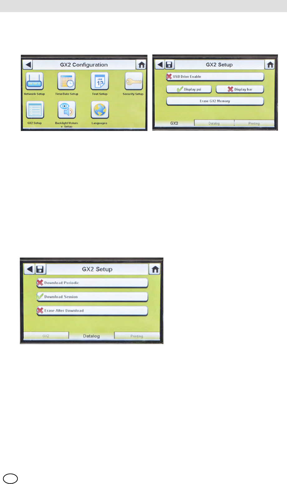
GX2 Setup
To access GX2 Setup, select GX2 Setup on the GALAXY GX2 Configuration screen [ Fig. 16].
GALAXY GX2 Tab
The following options are available on this screen:
-USB Drive Enable setting allows the user to gather data from the Memory card with a USB
drive that can be inserted in the port on the right side of the unit. The default setting is Off (2).
-Display psi or bar options display the units of pressure on the gauges on the home screen and
pressure screen. Selecting one of these options (3) will disable the other option. The default
setting is psi.
-Erase GALAXY GX2 Memory erases all data on the memory card. The user will be prompted
to confirm the action before erasure occurs.
Datalog Tab
The following options are available on this screen:
-Download Periodic setting will download the Periodic Datalog from the instrument following the
specified calibration or bump test. Downloading can be enabled or disabled. The default setting
is disabled (2).
-Download Session will download the Session Datalog from the instrument following the spec-
ified calibration or bump test. It contains the date and time stamp of instrument events, such
as turn on/off, alarms, and calibrations. The default setting is disabled (2).
-Erase After Download erases all current and past data once downloaded and verified by the
MSA Link Pro database. The default setting is enabled (3).
GALAXY GX2
34
Setting Up the GALAXY GX2 MSA
US
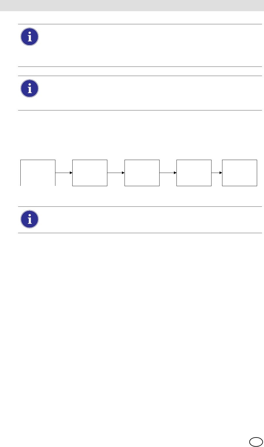
Datalog Download Sequence
The following flowchart shows the sequence of events for a datalog download:
Print Tab
Select the Print tab to print a calibration sticker or receipt [available from MSA, Fig 8]. The stick-
er or receipt will print in the language setting of the Master Test Stand.
-Print Sticker setting will print a calibration or bump sticker each time the GALAXY GX2
successfully calibrates or bumps an instrument. A sticker will not print if the instrument fails the
test.
-Print Receipt will print a receipt and embedded calibration sticker after calibration, or receipt
only after a bump. The receipt will print whether the instrument passes or fails, the calibration
sticker will only print with a passed calibration.
GX2 Gas Setup
The GALAXY GX2 Test Stand can accept test cylinder gas from the optional Cylinder Holders
(electronic and non-electronic) or from a user provided regulated gas source. Cylinder data can
be set for up to six gas types per cylinder. The following are the maximum number of gases each
instrument can process:
-ALTAIR and ALTAIR Pro: 1 gas
-ALTAIR 4/4X: 4 gases (typically 1 cylinder with quad gas)
-ALTAIR 5/5X: 5 gases (typically quad gas + 1 toxic gas)
-ALTAIR 5IR/5XIR: 6 gases
Datalogs are not written to the memory card because of potentially large file sizes. If the
unit is not networked to the MSA Link Pro software application, instrument datalogs
cannot be downloaded with the GALAXY GX2. In this situation the user can use the
MSA IR dongle and the free MSA Link application to download datalogs from the
instrument.
In order to effectively manage the time required to download datalogs, it is recommend-
ed that datalogs be downloaded and erased after each test. This will result in storage
of only the most recent information in the instrument datalog, minimizing time to
download the information.
Test Starts (Bump
or Calibration) Test Finishes Datalog download
starts immediately Datalog download
finishes
Test results (PASS
or FAIL) screen is
displayed
If either the Session or Periodic datalogs are Enabled for downloading, the test status
of the calibration or bump will not display until AFTER the datalog download is com-
plete.

MSA AUER
MSA
Setting Up the GALAXY GX2
GALAXY GX2 35
US
The GALAXY GX2 processes gas cylinder information and instrument readings in ppm,
%(volume) or %LEL. If using certified gas cylinders with the content specified in ppm, the most
accurate gas readings from the instrument will be obtained with the instrument set to ppm.
Conversions between ppm and mg/m3 are completed at standard pressure and temperature val-
ues. If the gas detector is set to display the readings in mg/m3, note that differences in the follow-
ing environmental conditions will cause the readings to be affected:
-Standard temperature: 20 ºC (68 ºF)
-Standard pressure: 101 kPa (760 torr)
An instrument can be set up with Comb EX as its combustible gas. Comb EX is combustible gas
that is not in the GALAXY GX2 database and must be manually entered. Hexane is an example
of a Comb EX gas that can be used for calibration, but is not listed in the database. Not all com-
bustible gases can be used to calibrate the ALTAIR family of gas detectors. If the Comb EX se-
lection is used, contact MSA to confirm your selected combustible calibration gas is compatible
with the instrument and GALAXY GX2.
To access all functionality of the GALAXY GX2 cylinder configuration capabilities,
an electronic Cylinder Holder must be connected to the GALAXY GX2.
GALAXY GX2
36
Setting Up the GALAXY GX2 MSA
US
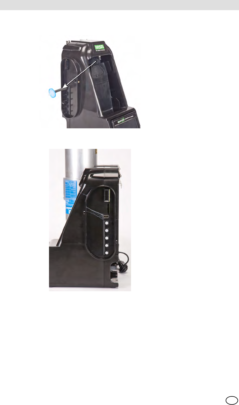
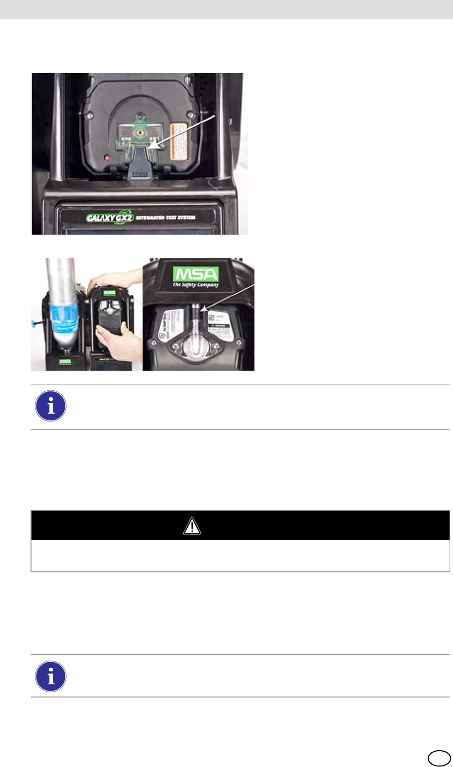
If the Test Stand is NOT using Cylinder Holders, the gas connections on the left-most
GALAXY GX2 Test Stand [ Fig. 17] are as follows from top:
-Fresh Air
-Cylinder 1
-Cylinder 2
-Cylinder 3
-Cylinder 4
Fig. 17 Gas inlets on the Test Stand
If the Test Stand is using Cylinder Holders [ Fig. 10], they are set up as follows from right to left:
-Cylinder 1 is the closest to the Test Stand.
-Cylinder 2 is to the left of Cylinder 1.
-Cylinder 3 is to the left of Cylinder 2.
-Cylinder 4 is to the left of Cylinder 3.
Fresh Air is the top port on the last installed (left-most) Cylinder Holder.
MSA AUER
MSA
Setting Up the GALAXY GX2
GALAXY GX2 37
US
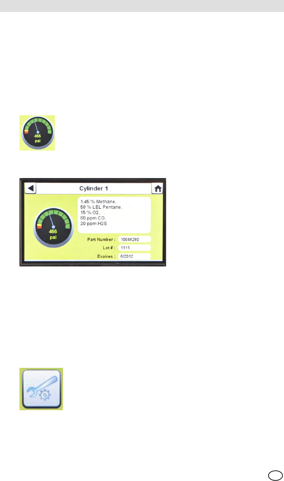
Changing Cylinders
Changing test cylinders in the Cylinder Holders is a simple procedure.
To change an RFID tagged test gas cylinder, using an electronic Cylinder Holder:
(1) Unscrew and remove a cylinder with its attached RFID tag from the Cylinder Holder.
(2) Screw a new test gas cylinder into the Cylinder Holder.
The Multi-Color Light Band will indicate test gas cylinder functionality as described in the System
Features -Cylinder Holder section [ chapter 2.5].
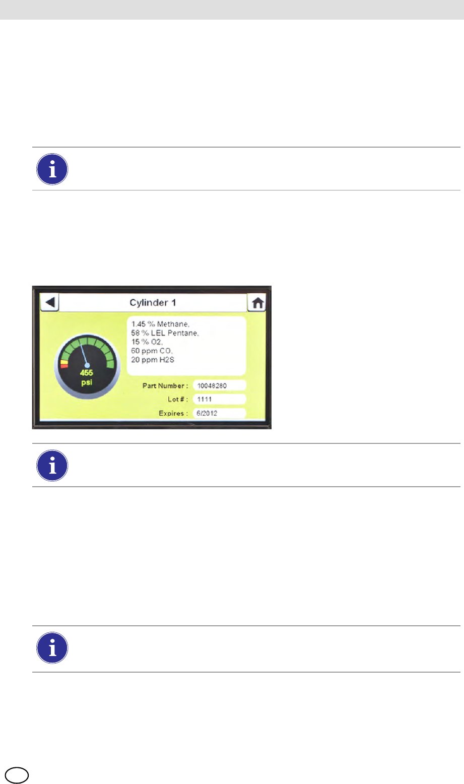
(3) Navigate to the Home screen and select the appropriate cylinder pressure gauge from the
touch screen.
ZThe selected Cylinder screen will appear, as shown.
To change a test gas cylinder, using a non-electronic Cylinder Holder:
(1) Remove the test gas cylinder from the Cylinder Holder.
(2) Unscrew the pressure regulator.
(3) Reattach the pressure regulator to the new test gas cylinder.
(4) Insert it into the Cylinder Holder.
(5) Navigate to the Home screen [ Fig. 23] and select the cylinder gauge to ensure the
GALAXY GX2 is reading the gas type.
The new cylinder's RFID tag will automatically populate the cylinder data fields on the
Cylinder Setup screens.
Ensure the GX2 is reading the pressure and gas type.
If a new gas type is used, the user must manually enter the cylinder data fields on the
Cylinder Setup screens, as described in the Cylinder Configuration section
[ chapter 4.7].
GALAXY GX2
38
Setting Up the GALAXY GX2 MSA
US
Network Setup (Optional)
The GALAXY GX2 can be networked to a PC with the MSA Link Pro software application. Net-
working (single or multiple connected units) allows the user to remotely gather and analyze data,
monitor performance, and configure the Test Stand.
An Ethernet cable supporting 10/100 Mb must be connected to the farthest right Ethernet jack
when facing the front of the unit, (shown in Fig. 6) and connected to the PC or network router.
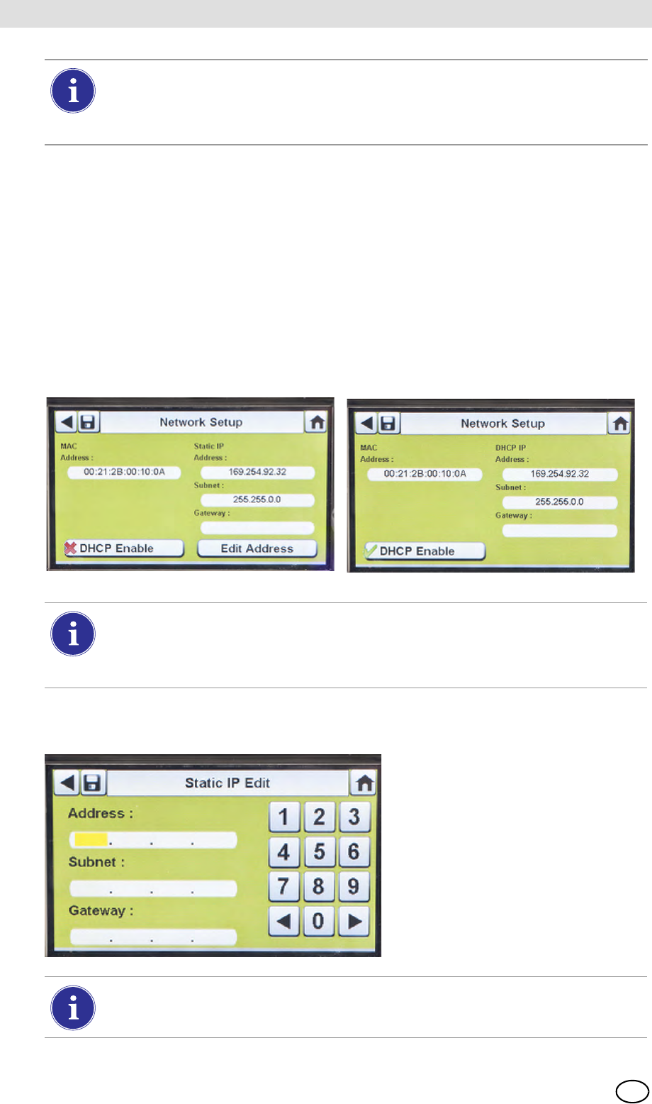
To configure the network setup, navigate to the GX2 Configuration screen and then select
Network Setup. The Network Setup screen displays. It is recommended to use a Static IP ad-
dress between the Master Test Stand and the MSA Link Pro application.
(1) If DHCP is disabled (2), select Edit Address on the Network Setup screen.
ZThe Static IP Edit screen displays.
If background gases could be present, connect a Zero Air Cylinder to any port on the
Cylinder Holder. MSA provides an RFID-tagged Air cylinder for this purpose. This re-
quires a calibration station with expanded solenoid capacity. Refer to the Introduction
section [ chapter 2] for more information about the expanded solenoid option.
Selecting DHCP Enable (3) allows the GALAXY GX2 to automatically receive an
IP address from the network. It is recommended that the DHCP server always assign
the same IP address to the Test Stand to maintain communications with the
MSA Link Pro application.
Corporate networks may require the involvement of an IT department for setup.
MSA AUER
MSA
Setting Up the GALAXY GX2
GALAXY GX2 39
US
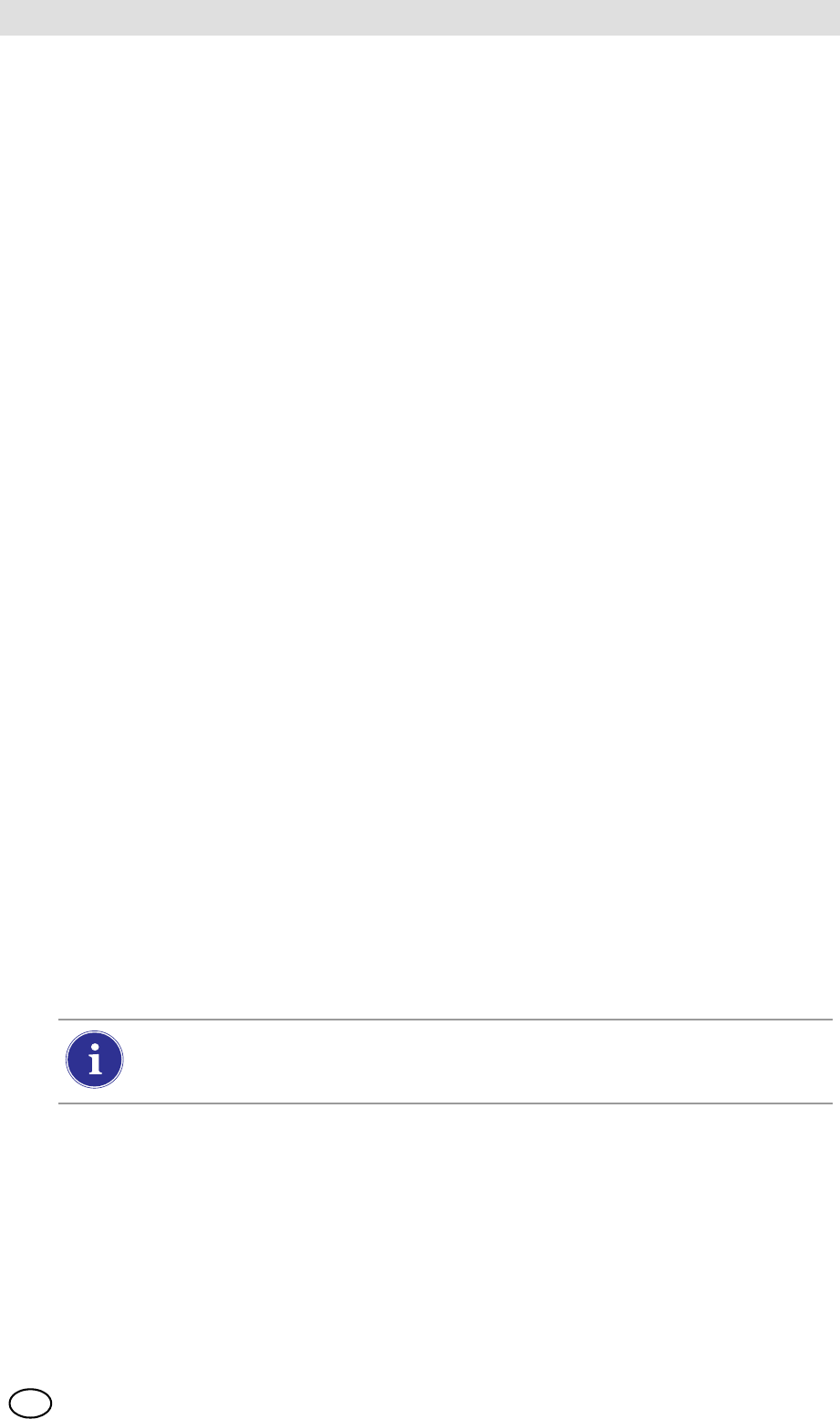
(2) Enter the Static IP Address on the number keypad.
ZThe yellow highlighted cursor then moves to the Subnet field.
(3) Enter the Subnet on the number keypad.
ZThe yellow highlighted cursor then moves to the Gateway field.
(4) Enter the Gateway on the number keypad.
ZThe yellow highlighted cursor then moves to the Subnet field.
(5) Select Save.
4.6 Instrument Configuration
The GALAXY GX2 Automated Test System allows the user to configure a limited set of gas de-
tector settings at the Test Stand, as defined below:
Gas Detector Settings Configurable at the Test Stand
The user can save those settings to a reusable file for later use [
The settings are stored on the Digital Secure USB (black) key. No instrument setting files are
stored locally.
The Instrument Configuration screens are accessed only when an instrument is inserted in the
Test Stand. To configure an instrument, insert the Digital Secure USB (black) key and navigate
to the Administrator page. Select GX2 Configuration screen [ Fig. 23] and then
Instrument Configuration. The Instrument Configuration screen displays.
-Time & Date (automatically set to the
Test Stand time & date)
-24-Hour Time
-Cal Gas Value
-Company Name
-Company Department Name
-User Name
-Exposure Warning
-Exposure Alarm
-TWA
-STEL
-Deficiency Warning
-Deficiency Alarm
-Alarm Set-point
-Latching Enabled
-Vibration Motor On/Off
-LED On/Off
-Horn Enable
-Man Down (if applicable)
-Enable/Disable Sensor Channel
-Cal Due On/Off
-Cal Due Interval
-Average Enabled
-Peak Enabled
-Datalog Interval
All settings entered in Instrument Configuration must be saved on the respective
screens. To apply settings to the instrument, the user must select
Update Settings before removing the instrument.
GALAXY GX2
40
Setting Up the GALAXY GX2 MSA
US
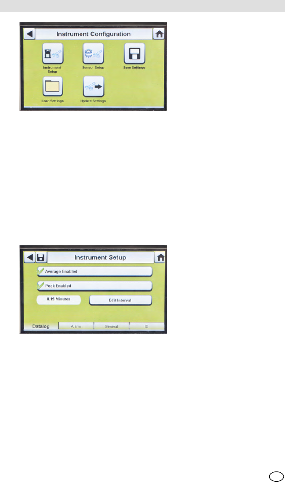
Fig. 18 Instrument Configuration
Instrument Setup
The user can set the instrument's datalog gathering functionality, alarms, calibration intervals, and
identification through the 4 tabs on the Instrument Setup page.
Select Instrument Setup [ Fig. 18] from the Instrument Configuration screen.
Datalog Tab
Select the Datalog tab to set how the instrument compiles sensor reading data during a
set interval.
Fig. 19 Instrument Setup - Datalog
-Average Enabled (3) compiles an average of the sensor readings during the set interval time.
-Peak Enabled (3) records the highest reading during the set interval time.
-Edit Interval allows the user to set a specific interval time frame for the recording of instrument
data to its datalog. The smaller this interval, the more frequent the data will be stored to the
datalog. Large datalogs will require longer download times.
1 Instrument Setup 4 Load Settings
2 Sensor Setup 5 Update Settings
3 Save Settings
MSA AUER
MSA
Setting Up the GALAXY GX2
GALAXY GX2 41
US
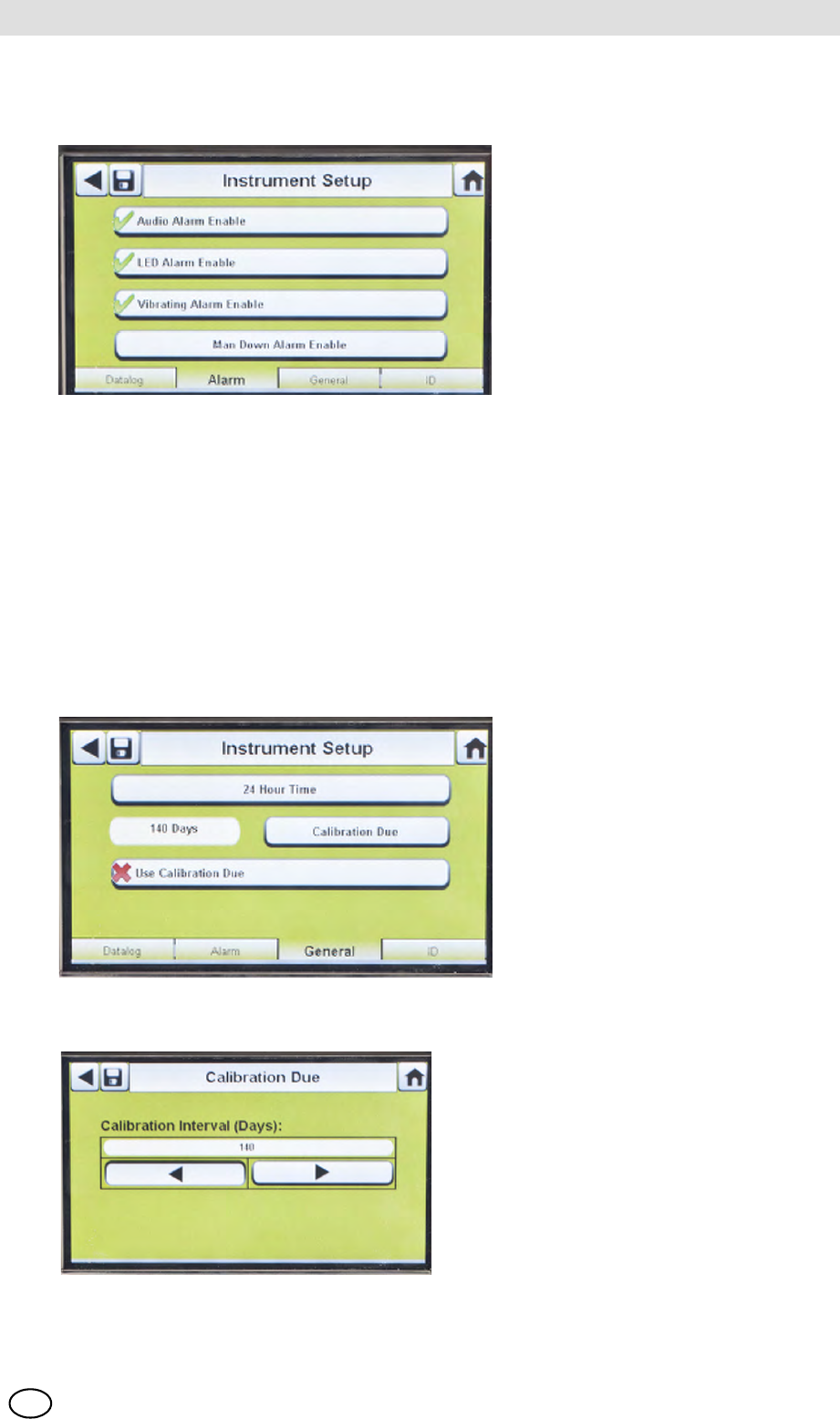
Alarms Tab
Select the Alarm tab to set the instrument alarm functionality.
Fig. 20 Instrument Setup - Alarm
-Audio Alarm Enable (3) sets the instrument to emit a beeping sound in an alarm condition.
-LED Alarm Enable (3) sets the instrument to flash its LEDs in an alarm condition.
-Vibrating Alarm Enable (3) sets the instrument to a vibrating alarm in an appropriate condition.
-Man Down Alarm Enable (if applicable) will activate the Audio and LED alarms if the instrument
does not detect motion for 30 seconds (select gas detectors equipped with this feature).
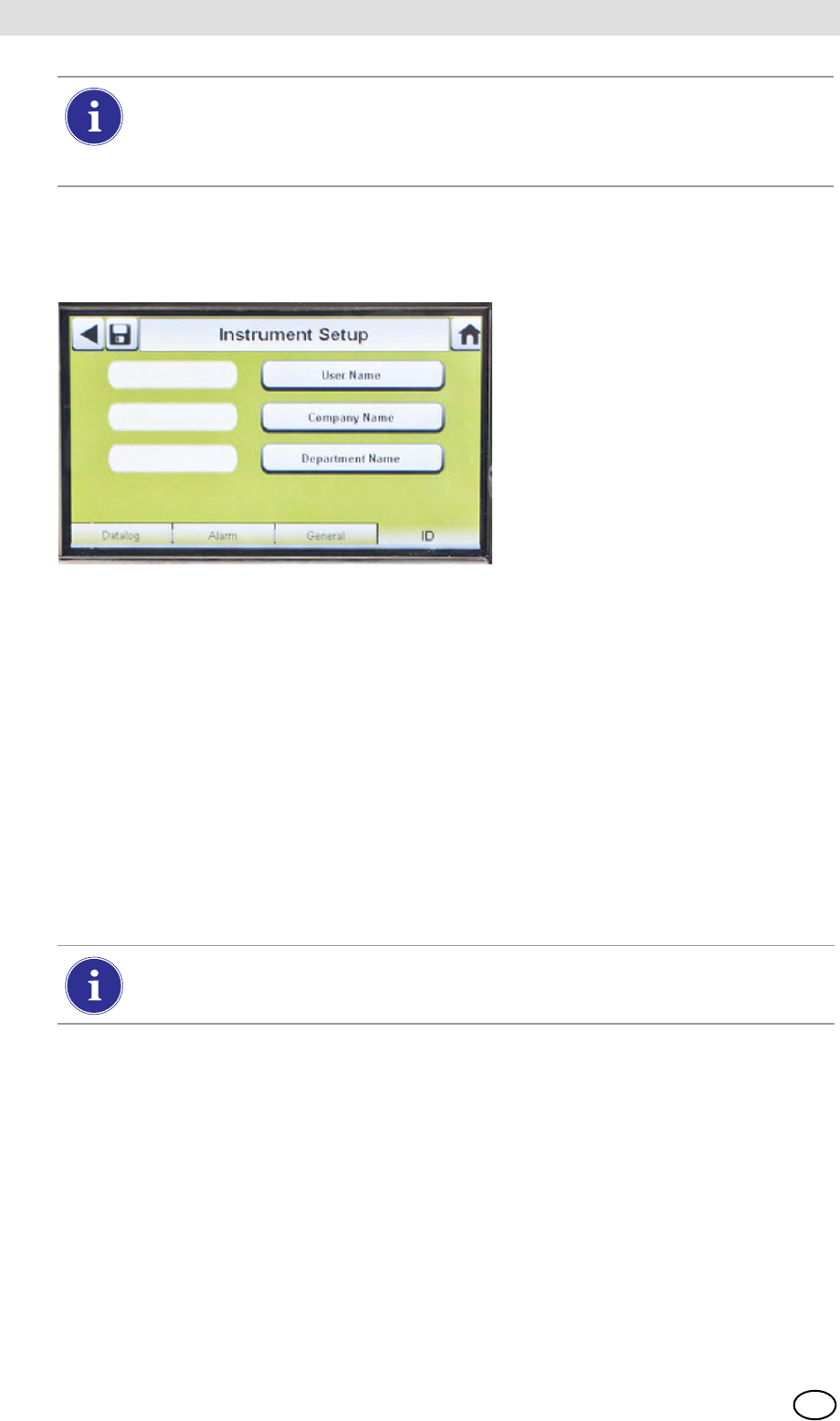
General Tab
Select the General tab to set the instrument calibration interval. The user can select a 24-hour
Time or 12-hour Time standard.
Fig. 21 Instrument Setup - General
(1) Select 24-Hour Time to set that stand-
ard. If not selected the instrument will
function in the default 12-Hour Time
standard.
(2) Select Calibration Due to set calibration
interval for the instrument.
ZThis Calibration Interval screen dis-
plays.
(3) Set the Calibration Interval (Days).
(4) Select Save.
GALAXY GX2
42
Setting Up the GALAXY GX2 MSA
US
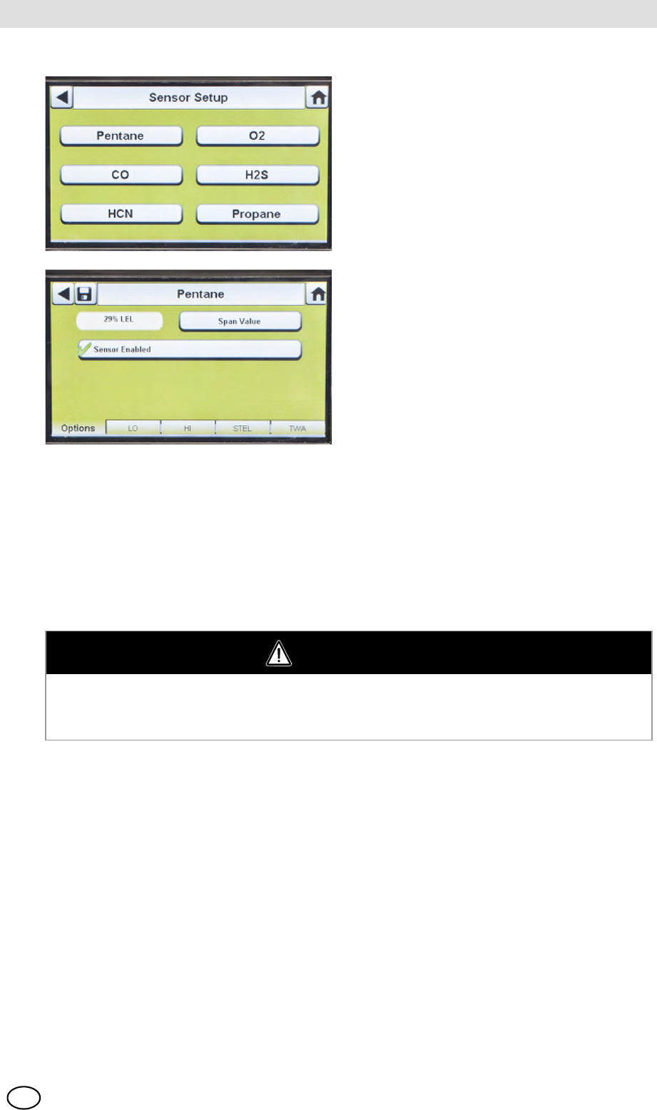
ID Tab
Select the ID tab to set the instrument name, company, and department.
Fig. 22 Instrument Setup - ID
(1) Select User Name to assign a designation.
(2) Enter the name on the keypad.
(3) Select Save and then select the back arrow.
(4) Select Company Name.
(5) Enter the name on the keypad.
(6) Select Save and then select the back arrow.
(7) Select Department Name.
(8) Enter the name on the keypad.
(9) Select Save.
Sensor Setup
The GALAXY GX2 displays the gas types the instrument is programmed to detect. The user can
enable or disable sensor settings, change span value, enable or disable alarms, and set alarm
latching. Adding new sensors or changing sensor types cannot be done in the GALAXY GX2.
These tasks must be completed at an MSA-authorized service center.
For proper operation, ensure the GALAXY GX2 and instrument Calibration Due
intervals are the same value. If not selected, calibration occurs based on the gas de-
tector Cal Interval. This can lead to more (or less, depending on setting) frequent instru-
ment calibration and unwanted overdue indications.
To apply settings to the instrument select Update Settings on the Instrument Configu-
ration screen [ Fig. 18], before removing the instrument from the GALAXY GX2.
MSA AUER
MSA
Setting Up the GALAXY GX2
GALAXY GX2 43
US
Options Tab
Select the Options tab to set Span Value and enable or disable the sensor for that gas type.
(1) Select Span Value to enter the calibration and bump span value. Check the instrument's
product user manual for recommended span value of each sensor.
ZThe GALAXY GX2 will prohibit entering span values outside the instrument range. The in-
strument will transmit its range to the Test Stand.
(2) Enter the Span Value on the number keypad.
(3) Select Save and then select the back arrow.
(1) Select Sensor Setup from the Instru-
ment Configuration screen [ Fig. 18].
ZThis screen displays the sensors cur-
rently installed in the instrument.
(2) Select the sensor that you wish to con-
figure on the Sensor Setup screen.
WARNING
Using an incorrect span value can seriously impair the gas detector's ability to warn the user of
dangerous conditions. The gas detector could fail to perform as designed and persons who rely
on this product for their safety could sustain severe personal injury or loss of life.
GALAXY GX2
44
Setting Up the GALAXY GX2 MSA
US
Alarm Setpoint Tabs
Select the LO, HI, STEL, and TWA tabs to enable each alarm, determine setpoints, or enable
latching for each sensor.
The GALAXY GX2 will read alarm limits from the instrument and prevent entered values from ex-
ceeding those limits.
-LO is a warning alarm that indicates the instrument is exposed to a gas level above the first
alarm level. For an oxygen sensor, this alarm level can also be less than 20.7 %Vol.
-HI is a warning alarm that indicates the instrument is exposed to a gas level above the second
alarm level. For an oxygen sensor, this alarm level can also be less than 20.7 %Vol.
-STEL is the Short Term Exposure Limit warning alarm that indicates the instrument is exposed
to a higher than acceptable gas threshold for 15 minutes.
-TWA is the Time Waited Average that projects the current gas readings over an 8-hour period.
The warning alarm indicates if projections reach a higher than acceptable threshold.
To change the Alarm Setpoint:
(1) Select Alarm Setpoint from the LO, HI, STEL, or TWA tabbed screens.
(2) Enter the setpoint on the number keypad.
(3) Select Save.
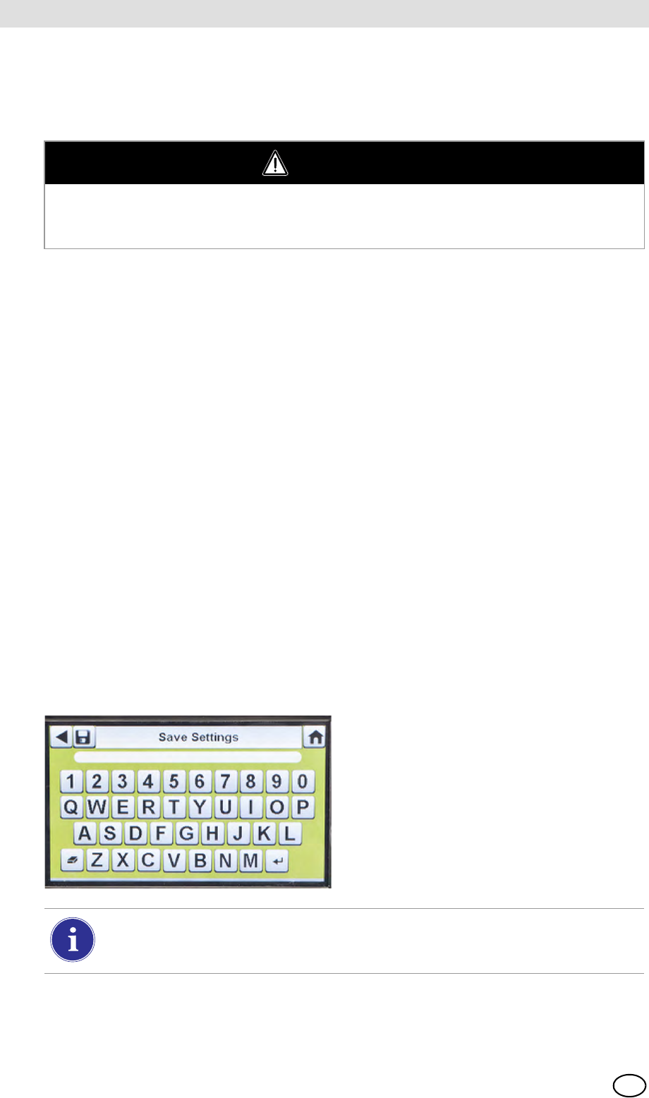
Save Settings
Once the instrument settings are configured, these settings can be saved to a USB drive for future
application onto another instrument.
WARNING
Using an incorrect alarm setting can seriously impair the gas detector's ability to warn the user
of dangerous conditions. Extreme caution must be used when changing alarm levels. Ensure
alarm changes are properly set prior to instrument use.
(1) Select Save Settings () from the
Instrument Configuration screen.
(2) Enter a file name for the settings on the
keypad.
The file name is limited to 24 Western language characters. It is recommended that a
detailed description of changed settings for each file be kept in a secure location to en-
sure proper gas detector configuration.
(3) Select Save.
MSA AUER
MSA
Setting Up the GALAXY GX2
GALAXY GX2 45
US
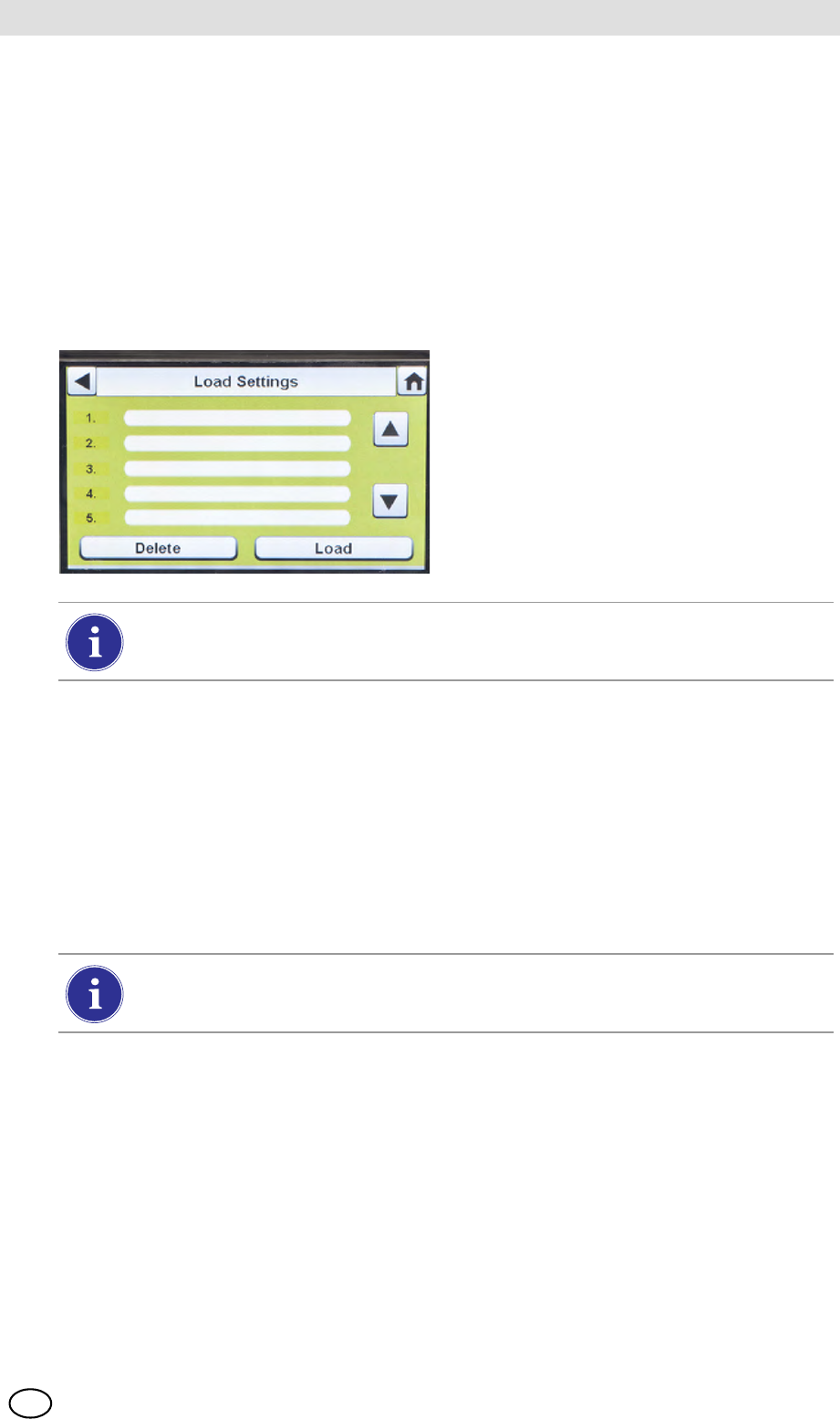
Load/Delete Settings
Configured instrument settings can be loaded into the GALAXY GX2 and applied to an instrument,
provided the black USB key is inserted into the Master Test Stand as described in the USB Drives
section [ chapter 2.4] of the System Features section.
This feature is particularly useful when configuring a large number of instruments. Unused set-
tings may be permanently deleted from the Test Stand. Pre-defined settings from a USB drive can
be efficiently transferred.
To load or delete settings:
(4) Select the up or down arrows to indicate the file name of the setting to apply.
(5) Select Load to apply the setting to the instrument.
Select Delete to permanently remove the setting from the USB drive.
(6) Select the Back Arrow on the top left of the screen to navigate to the
Instrument Configuration screen.
Update Settings
Select Update Settings to save or delete the settings on the instrument.
(1) Insert a USB drive with the Saved set-
tings into the port, under the memory
card port on the right side of the Test
Stand.
(2) Select Instrument Configuration on
the Home screen.
(3) Select Load Settings on the Instrument
Configuration screen.
Saved settings on the black USB key display.
Repeat the Load Settings and Update Settings steps for each new instrument that is
to be changed.
GALAXY GX2
46
Setting Up the GALAXY GX2 MSA
US
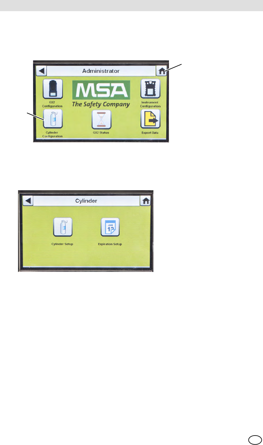
4.7 Cylinder Configuration
The user can configure the GALAXY GX2 to change assigned gases in each cylinder holder
attached to the Test Stand(s).
(1) To access Cylinder Configuration, navigate to the Administrator screen:
Fig. 23 Administrator screen
(2) Select Cylinder Configuration.
ZThe Cylinder screen displays.
1 Icon - Cylinder Configuration 2 Icon - Home Screen
2
1
MSA AUER
MSA
Setting Up the GALAXY GX2
GALAXY GX2 47
US
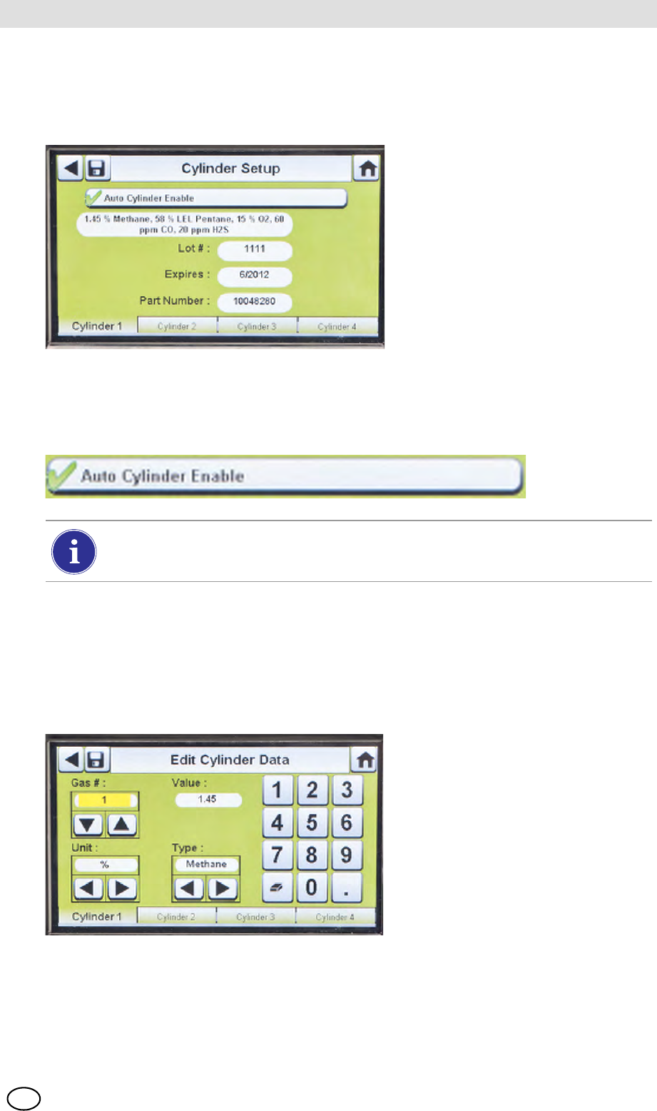
Cylinder Setup
Select Cylinder Setup.
ZThe Cylinder Setup screen displays for Cylinder 1, which is the cylinder closest to the
Test Stand.
Cylinder Tabs
Cylinder data will populate automatically when using the electronic cylinder holder and a test gas
cylinder with RFID tag. This feature is enabled when this button appears as shown:
To enter cylinder data, if not using an electronic cylinder holder:
(1) Select "2" on the Auto Cylinder Enable button for manual entry.
(2) Select Edit on the Cylinder Setup screen.
(3) The user will be prompted to Save Changes? Select Yes.
ZThe Edit Cylinder Data screen displays.
(4) Set the Gas # by selecting either the up or down arrows. If there is one gas in the cylinder,
select 1. For additional gases in the same cylinder (gases 2-6), enter the gas parameters.
Example: if Cylinder 1 contains quad gas, four sets of gas parameters should be entered
(gases 1, 2, 3, and 4). To remove a gas from the list, set the Value to zero (0), Units and Type to
None, and then select Save.
The Lot # and Expires fields cannot be manually entered. They are populated only
when using an electronic cylinder holder.
GALAXY GX2
48
Setting Up the GALAXY GX2 MSA
US
(5) Set the Unit by selecting either the left or right arrows.
(6) Set the Value by entering the correct value on the number keypad.
(7) Set the Type by selecting either the left or right arrows.
(8) Select Save.
(9) Repeat steps 1 through 6 for each cylinder (maximum of 4 cylinders).
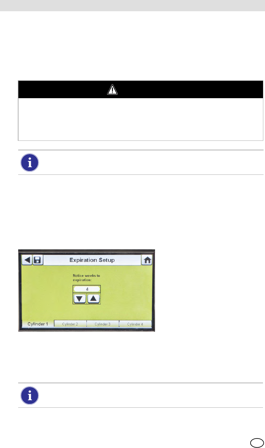
Expiration Setup
When using the electronic Cylinder Holder, the gas cylinder expiration date is automatically read
from the RFID tag. The Test Stand can send an email notification (if configured) of the pending
expiration prior to the expiration date. The user must define how many weeks in advance the
notification is sent. This time period is suggested to be the lead-time to replace/reorder the cyl-
inder.
Select Expiration Setup on the Cylinder screen to access the cylinder Expiration Setup screens.
(1) Set the Notice weeks to expiration by selecting either the up or down arrows.
ZThe default value is 4 weeks.
(2) Select Save.
(3) Repeat steps 1 and 2 for each cylinder.
WARNING
Proper setup of non-RFID tagged gas cylinders is critical. Accurate calibration may not occur if
improper cylinder values are entered. The user must also confirm the cylinder gas concentration
is compatible with the respective instruments that are to be calibrated. The gas detector could
fail to perform as designed and persons who rely on this product for their safety could sustain
severe personal injury or loss of life.
The GALAXY GX2 will prohibit entering gas values greater than 75%LEL for
combustible gases.
This feature is only available for electronic Cylinder Holders with RFID tagged test gas
cylinders.
MSA AUER
MSA
Using the GALAXY GX2
GALAXY GX2 49
US
5 Using the GALAXY GX2
Once the GALAXY GX2 is set up and configured to accept a gas detector, the user must complete
the following steps to perform instrument tests.
5.1 Turning on the System
The system is turned on when the AC Power Module or Vehicle Power Adapter is plugged into the
unit and a reliable power supply is provided. The GALAXY GX2 does not have an on/off button
and is designed to remain powered on.
5.2 Inserting the Instrument
The GALAXY GX2 includes one of three instrument cradles to accommodate the ALTAIR family
of gas detectors.
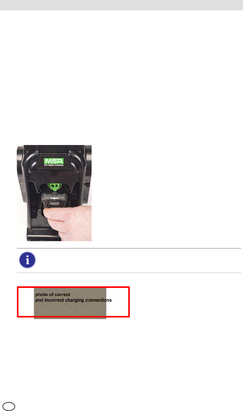
To insert all instruments, except the ALTAIR 5/5X:
(1) Insert the bottom of the instrument into the cradle and
push the top until it snaps into place.
There is a several second delay between the insertion of the instrument and start of gas
testing while communications are established. A Progress screen displays when gas
testing starts.
(2) If using the charging option on the
ALTAIR 4/4X ensure the Test Stand
charging connector at the bottom of
the cradle makes contact with the in-
strument contact.
DUM-
GALAXY GX2
50
Using the GALAXY GX2 MSA
US
To insert the ALTAIR 5/5X:
5.3 Running a Test
Complete the following steps to run an instrument test:
(1) Turn on the gas detector and allow it to warm up per the appropriate instrument manual.
(2) Ensure the test gas cylinder tubing is properly attached to the barb fitting of the gas inlet, or
that the cylinder(s) are properly screwed into the Cylinder Holder(s) and contain gas.
(3) Verify the selected mode, indicated in the top left corner of the Home screen.
(Calibration Only, Bump Only, or Bump/Cal on Fail.)
(1) Insert the instrument into the cradle,
sliding the bottom over the charging
connector.
If your Test Stand has the optional
charging feature, ensure the
charging connector at the bottom
of the cradle makes contact with
the instrument contact.
(2) Pivot the instrument in the cradle up-
wards, into the gas inlet sleeve
(see arrow). The instrument will lock
into place, once properly positioned.
(3) Ensure the red LEDs on the instru-
ment flash when communicating with
the Test Stand.
There is a several second delay between the insertion of the instrument and start of gas
testing while communications are established. A Progress screen displays when gas
testing starts.
WARNING
Instrument must warm up per the instrument manual before attempting calibration; failing to al-
low unit to warm up can cause erroneous test results, which can cause inaccurate calibrations.
If the desired mode is not set, refer to the GALAXY GX2 Setup section [ chapter 4.5]
of this manual.
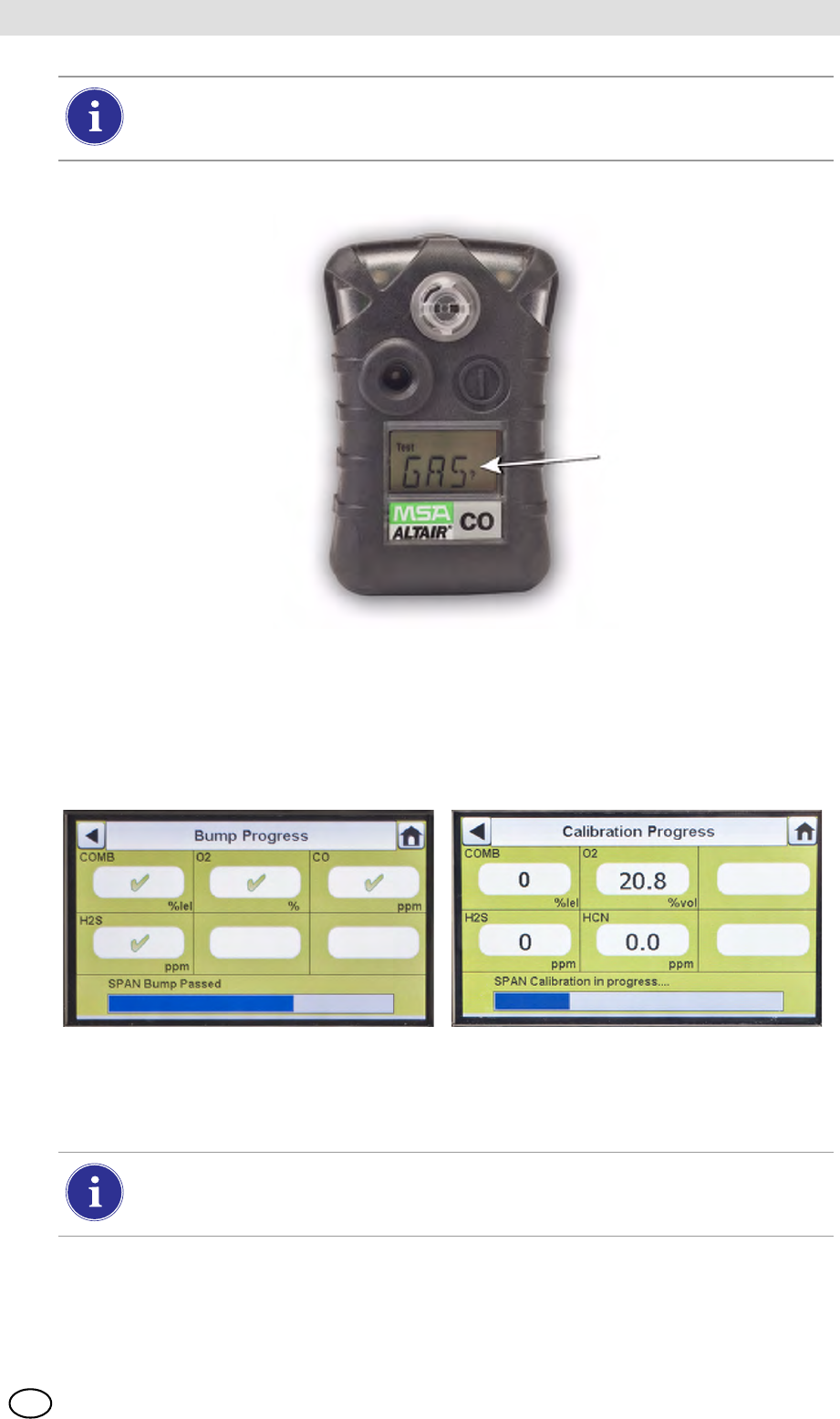
MSA AUER
MSA
Using the GALAXY GX2
GALAXY GX2 51
US
(4) Insert the instrument into the Test Stand cradle.
(5) The GALAXY GX2 will read the instrument configuration via the IR link up to 10 seconds. If
the LED lights on the instrument flash red do not remove the instrument. This indicates that
IR communications are in progress.
(6) After the initial IR communications, the bump or calibration progress screen displays that in-
cludes up to six gas types and a progress bar.
For the Bump Progress screen, an hourglass symbol will display in each sensor box until that sen-
sor's bump is complete. A green checkmark (3) or red X (2) will display for each sensor when
the Bump test is complete.
Before inserting an ALTAIR or ALTAIR Pro into the Test Stand, press and hold the
instrument Test button for one second. The screen on the gas detector should display
Gas? prior to inserting it into the Test Stand (see photo below).
If the Test Stand is configured to download the session log and/or periodic log from the
instrument, the download will occur after the calibration or bump test. Refer to the
GALAXY GX2 Setup section [ chapter 4.5] to configure this feature.
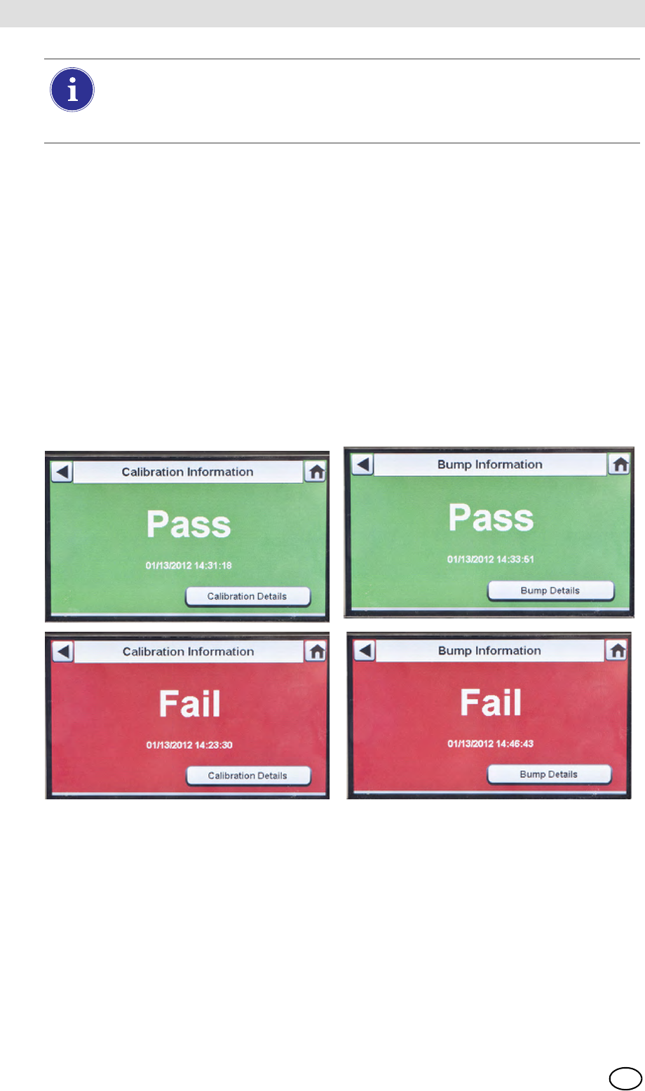
GALAXY GX2
52
Using the GALAXY GX2 MSA
US
Reminder: Instrument datalogs can only be downloaded when an Ethernet connection to
MSA Link Pro is active or via an IR Dongle to MSA Link.
Helpful Hint: Instrument Periodic datalogs can grow large and create lengthy download times,
particularly for the ALTAIR 5/5X. MSA recommends downloading and then erasing Periodic data-
logs after every test. Erase Datalog is the default setting.
The GX2 will only erase instrument datalogs after receiving confirmation from MSA Link Pro that
data is successfully stored. If the software application is inactive the Test Stand displays a mes-
sage stating datalogs cannot be downloaded.
(7) The instrument Pass or Fail screen displays. This screen displays until a new instrument is
inserted or the user makes another selection on the touch screen. If datalog downloads are
enabled, the screen will indicate the status of the download (Successful or Failed) at the
completion of the data transfer.
If the instrument passes the test, remove it or select Home.
If the instrument fails the test, select Calibration Details or Bump Details for sensor failure
information.
If the instrument is removed while the Test Stand is performing a calibration or bump
the instrument will default to the last valid and retained calibration parameters. For gas
detectors with multiple sensors, any green colored calibration progress values are con-
sidered a valid calibration.
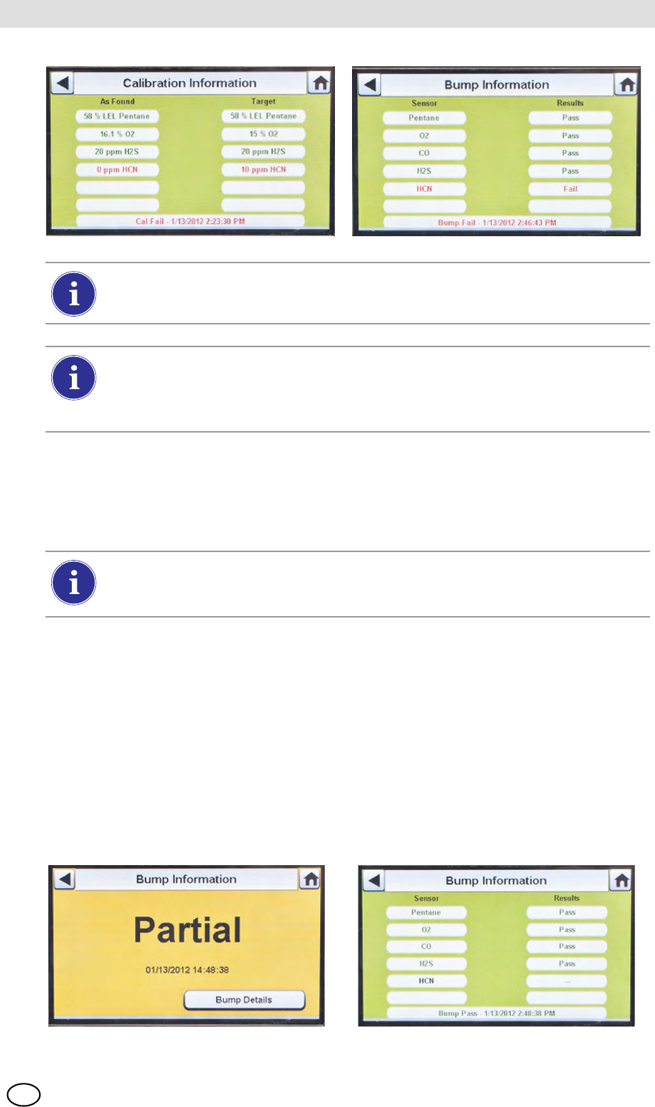
MSA AUER
MSA
Using the GALAXY GX2
GALAXY GX2 53
US
If a sensor failed during a bump, attempt to calibrate the instrument. Refer to calibrate an
instrument in this manual.
If the unit fails the calibration, review the troubleshooting section [ chapter 6] of this man-
ual.
If Cylinder is Configured Incorrectly or Gas is Not Available
The Test Stand will verify the instrument sensors are compatible with the gases in the cylinder(s).
If not, the GALAXY GX2 will:
(1) Prompt the user to run a partial bump or calibration.
(2) If a partial bump or calibration is acceptable, select Yes.
If not, select Home to navigate to the administrator screen.
ZIf a partial bump or calibration is performed the test results screen displays.
ZDashes (---) under the results column indicate unavailable gases for the test.
If the instrument fails the bump test while the mode is set to Bump/Cal on Fail the Test
Stand will automatically calibrate the instrument.
The Calibration Information screen displays two columns for the sensors: As Found and
Target. As Found is what the Test Stand detected prior to calibration. The Target col-
umn specifies the span gas value that is being applied. If the sensor passes calibration,
the Target value becomes the new calibration point.
If using the ALTAIR 4/4X or 5/5X the instrument will shut off if not removed from the Test
Stand within 5 minutes after test completion. If the GALAXY GX2 is equipped with the
charging option the instrument will begin charging after shutoff.
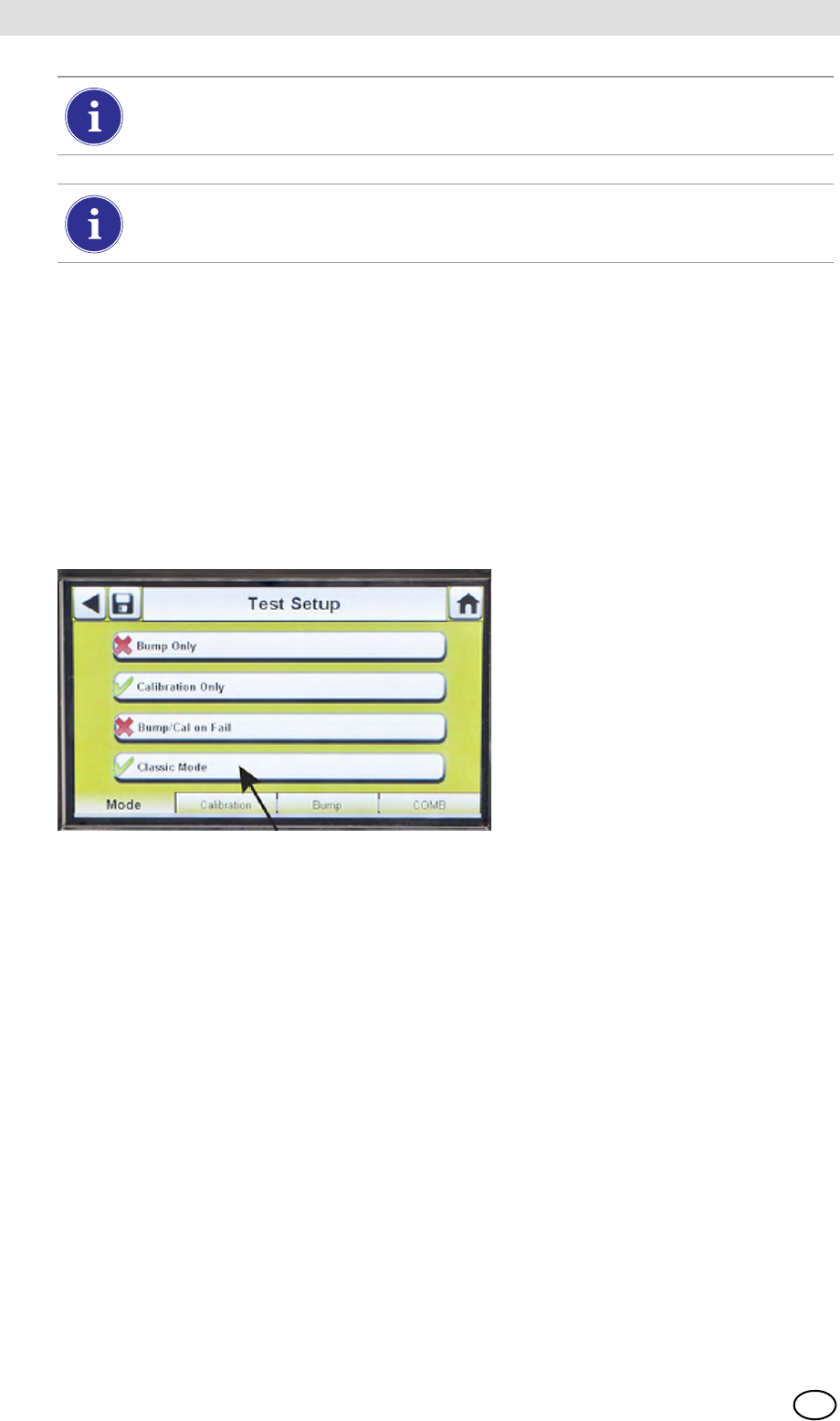
GALAXY GX2
54
Using the GALAXY GX2 MSA
US
After Setup is complete:
After initial installation and setup are complete, confirm the GALAXY GX2 is properly configured.
Perform manual calibrations on several instruments and then repeat the calibration using the
GALAXY GX2. Confirm the calibration results are equivalent.
5.4 Classic Mode
If the Classic Mode button is enabled (3), every time a gas detector is inserted in the Test Stand
it will be tested according to the user-selected Mode. This feature ignores the Calibration and
Bump Interval.
Fig. 24 Test Setup
If the user disables the Classic Mode (2) and datalog downloading is enabled, the Test Stand will
determine if testing is due. If not, the Test Stand downloads the datalogs.
If performing a manual bump or calibration on an individual sensor in a multi-gas detec-
tor, always perform the manual test after the GALAXY GX2 test is complete.
If using MSA Link Pro software, partial bump tests will result in the instrument being list-
ed as "Overdue" for bump testing since not all sensors were tested.
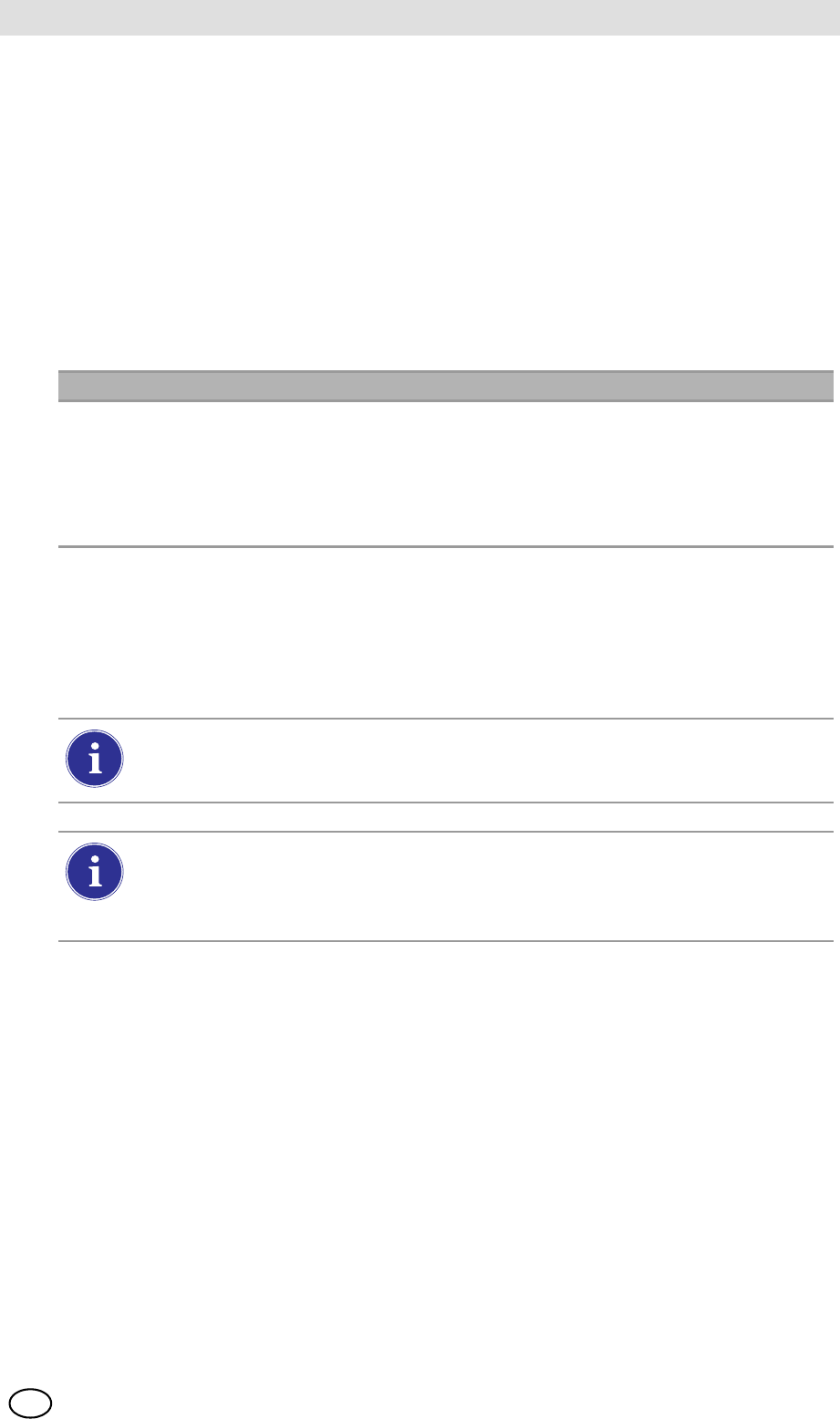
MSA AUER
MSA
Using the GALAXY GX2
GALAXY GX2 55
US
5.5 GALAXY GX2 Always Ready Feature
The Always Ready feature is a capability of the ALTAIR 4X and ALTAIR 5X with the following
software versions:
-ALTAIR 4X: v2.03 and higher
-ALTAIR 5X: v1.11 and higher
The feature permits the gas detector to be automatically calibrated on a user-defined interval. The
most common use of this feature allows the user to configure the GALAXY GX2 to automatically
calibrate an instrument prior to the start of work-shift.
The following configurations must be set to allow the Always Ready feature to be active:
When these conditions are met, every hour the instrument will internally check its clock and last
calibration time and date. If the next calibration is due to occur within the hour, the gas detector
powers itself on and the Test Stand will initiate the calibration. Following calibration, the Test
Stand will power off the instrument and begin charging. The sequence repeats based on the
Calibration Due Interval.
Instrument GALAXY GX2 Test Stand
-Calibration Due Interval = any interval
[ chapter 4.6]. Ensure that this interval is
the same as on the Test Stand.
-Valid calibration at the desired time of day
-Charging version of the Test Stand
-Calibration Due Interval = any interval
[ chapter 4.6]. Ensure that this interval is
the same as on the gas detector.
-Test Mode = Calibration
The Always Ready feature is solely based on Calibration Due Interval, not on time of
day. Each subsequent calibration starts within the same hour of the day as the previous
calibration.
If for some reason the instrument fails calibration two times in a row, the Always Ready
feature will be disabled in the instrument to prevent calibration gas from being unnec-
essarily consumed. The user must diagnose the cause of the failed calibrations and in-
itiate a valid calibration at the desired time of day.
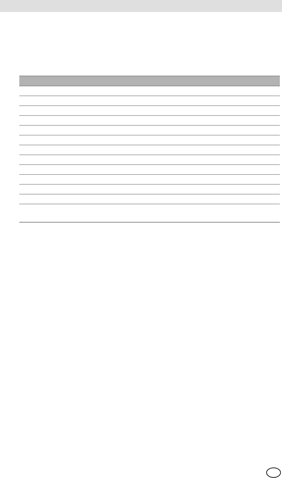
GALAXY GX2
56
Using the GALAXY GX2 MSA
US
5.6 E-mail Notification
If a network connection is active and e-mail notification is configured via the MSA Link Pro
software, the Master Test Stand will send e-mails based on the events shown in the table below.
The MSA Link Pro user can configure which day(s) of the week that e-mails are sent and for which
conditions. Note that "EO" = Each Occurrence and "FO" = First Occurrence.
5.7 Overdue Calibration and Bump Notification
The Test Stand will determine that gas detectors are overdue for a bump or calibration and send
notification per the table above. Gas detectors are flagged as overdue on the day following the
due date.
Frequency Condition for Email e-mail is sent when
FO Low Calibration Gas Gas cylinder pressure ≤99 psi
FO Empty Calibration Gas Gas cylinder pressure ≤49 psi
FO Calibration Gas Nearing Expiration Date User configurable (default = 4 weeks)
FO Calibration Gas Expired Day of expiration
FO GX2 Faults/Errors As they occur
FO SD Memory Card Nearing Full 90% Full
FO SD Memory Card Full 99% Full
EO Security Accessed After password is entered
EO Bump Overdue User configurable (default = 1 day)
EO Calibration Overdue User configurable (default = 30 days)
EO Bump Failed As they occur
EO Calibration Failed As they occur
EO X-Cell Sensor Status Reported after 2 successive
failed calibrations
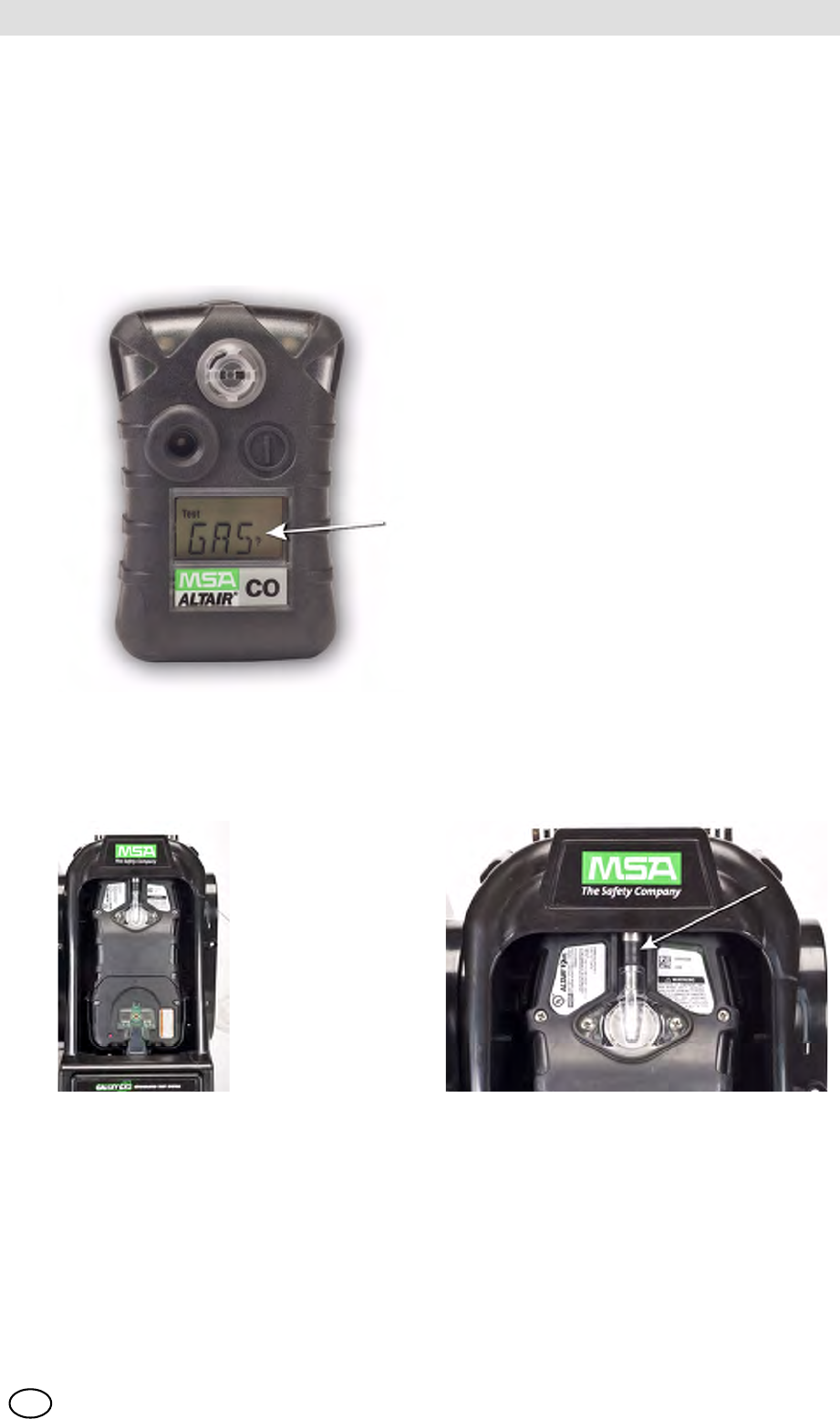
MSA AUER
MSA
Troubleshooting
GALAXY GX2 57
US
6 Troubleshooting
Use the following information to diagnose abnormal conditions.
6.1 Instrument Will Not Initiate a Bump or Calibration
(1) Ensure the instrument is turned on and errors are not displayed.
(2) If using an ALTAIR or ALTAIR Pro, press and hold the button for one second. The screen on
the gas detector must display Gas? prior to insertion into the Test Stand.
(3) Ensure the instrument is seated securely in the Test Stand cradle.
(4) If using the ALTAIR 5 or 5X, ensure the instrument pump inlet is seated securely in the
Test Stand gas inlet sleeve.
(5) Verify errors are not displayed from the electronic Cylinder Holder. If using the non-electronic
Cylinder Holder, ensure adequate connections are made and verify cylinder pressure.
(6) If using a GALAXY GX2 with the charging option for the ALTAIR 4/4X or 5/5X ensure the
charging connection fits securely to the instrument. This properly aligns the instrument in the
test stand.
(7) Ensure the GALAXY GX2 is set in the desired test mode. Refer to the GALAXY GX2
Configuration [ chapter 4.5] in the Setup section of this manual.
GALAXY GX2
58
Troubleshooting MSA
US
6.2 Instrument Fails Zero Calibration or Bump
(1) Check the Fresh Air filter and replace if contaminated.
(2) If not using zero gas, ensure that the atmosphere is free of any interfering gas.
(3) If connecting test gas without a Cylinder Holder, ensure the gas tubing line is not connected
to the top fresh air port on the left side of the farthest left unit.
6.3 Instrument Fails Span Calibration or Bump
(1) Verify the instrument span setting is the same value as the test gas.
(2) For ALTAIR H2S and ALTAIR CO instruments, ensure that the green gas seal is inserted in
the Test Stand.
(3) For ALTAIR 5/5X instruments, verify that the gas inlet on the instrument is fully inside the
inlet nozzle on the Test Stand.
(4) Check the right side of the farthest right unit to ensure the white plugs are secure over the
gas outlet connections.
(5) Check the sides of each unit to ensure the gas line barb fittings are in place and aligned
between the Test Stands and Cylinder Holders. Misaligned barbs lead to gas leakage.
(6) Ensure the cylinder configuration is correct. Refer to the Cylinder Configuration information
in the Setup section [ chapter 4.7] of this manual.
(7) Use the Details screen to identify failing sensor(s). If repeated failures occur, replace sensor
per instrument manual instructions.
6.4 Instrument Records Do Not Display
Instrument records only display in the farthest right Test Stand. Check the memory card port in
the right side port of the farthest right Test Stand. If the optional SD or SDHC memory card is not
installed, the instrument cal and bump records will not display.
Test Records Not Saved to Memory Card
Most likely caused by a corrupted memory card or new card that is write protected. In the case of
a write protected memory card, slide the switch on the side of the card to set it to accept data.
Occasionally, in normal use conditions, electrochemical sensors can be exposed to
either very high levels of the target gas or to an interferent gas, which can saturate the
sensor electrolyte or filter. If this type of saturation occurs, it may affect the sensors per-
formance and ability to zero or span calibrate. This is typically a temporary effect and
the sensor will self-recover if left in fresh air. The recovery time is dependent on the
saturation gas and the level of exposure, but is less than 24 hours in almost all cases.
Recovery should be attempted prior to sensor replacement.
MSA AUER
MSA
Troubleshooting
GALAXY GX2 59
US
6.5 Cylinder Data Does Not Display
If using an electronic Cylinder Holder with RFID-tagged MSA gas cylinders, the general cylinder
parameters automatically populate. If using a non-electronic Cylinder Holder or test gas from an
independent source the user must manually enter cylinder data. Gas cylinder pressure will ONLY
display with an electronic Cylinder Holder.
Cylinder Data Does Not Display:
(1) If using an electronic Cylinder Holder, verify the pressure is displayed on the Home screen.
If not displayed, the Cylinder Holder and Test Stand may not be communicating via the con-
nector. Remove the flange screws and push the two stands together. If a valid pressure read-
ing displays re-insert the flange screws.
(2) If using an electronic Cylinder Holder, ensure the test gas cylinder is properly screwed into
the base.
(3) If not using an RFID-tagged gas cylinder, verify that cylinder parameters have been entered
[ GX2 Gas Setup].
(4) Using an independent regulator, ensure the test cylinder(s) contain test gas.
(5) If not using an electronic Cylinder Holder, ensure the cylinder description is entered in the
cylinder set up screens. Refer to the cylinder configuration set up section [ chapter 4.7] of
this manual.
6.6 Test Stand Yellow LED Blinking
The Test Stand provides a comprehensive status of hardware and firmware components through
the GX2 Status screen, accessed on the Administrator screen [ Fig. 23] by selecting the
GX2 Status button. The table below shows the information reported for each Test Stand and
Cylinder Holder in a bank. If one of these components is in Fault, a red message displays,
indicating the error.
The cylinder gauges on the Home screen and the subsequent cylinder screens only dis-
play pressure, Part Number, Lot Number, and Expiration fields if using an electronic
Cylinder Holder.
Cylinder Holder (number) If Status is Fail, then:
-Cylinder Gas Indicates a fault condition with the cylinder (expired or empty)
-Flash Memory Return to an Authorized MSA Service Center for repair
-RAM Memory Return to an Authorized MSA Service Center for repair
-Power Supply 12V Return to an Authorized MSA Service Center for repair
-Power Supply 6V If GX2 6V power supply shows failed, try reconnecting.
Otherwise, return to an Authorized MSA Service Center for repair
-RFID Tag Return to an Authorized MSA Service Center for repair
-Communications Return to an Authorized MSA Service Center for repair
- RFID Read Corrupt RFID tag. Enter cylinder information via manual setup
screens.
-Data Corrupt RFID tag. Enter cylinder information via manual setup
screens.
GALAXY GX2
60
Troubleshooting MSA
US
-CRC Corrupt RFID tag. Enter cylinder information via manual setup
screens.
-Identifier
Test Stand (number) If Status is Fail, then:
-IR Cycle power to the Test Stand. Ensure there is no dirt on the gas
detector blocking the IR interface. If the problem persists, return to
an Authorized MSA Service Center for repair.
-Pump chapter 6, under Pump Fault or Flow Fault
-Flow chapter 6, under Pump Fault or Flow Fault
-SD Card 90% Full Replace SD card or delete files.
-SD Card 100% Full Replace SD card or delete files.
-Power Supply 6V If another GX2 power supply is available, try exchanging power
supplies. Otherwise, return to an Authorized MSA Service Center
for repair.
-Power Supply 1.8 Return to an Authorized MSA Service Center for repair
-Data A setting was corrupted and factory defaults have been restored for
all settings. Verify all GX2 settings are correct for your application.
-CRC A setting was corrupted and factory defaults have been restored for
all settings. Verify all GX2 settings are correct for your application.
-Configuration Reset This occurs when a Data or CRC fault is detected. This means that
factory defaults have been restored. If this error returns while
making setting changes, return to an Authorized MSA Service
Center for repair.
-Cylinder Comm Communications between the Test Stand and the Cylinder Holder
is disrupted. Verify Cylinder Holder LED status shows green; push
units together to ensure good connection; if problem persists, return
to an Authorized MSA Service Center for repair.
Cylinder Holder (number) If Status is Fail, then:
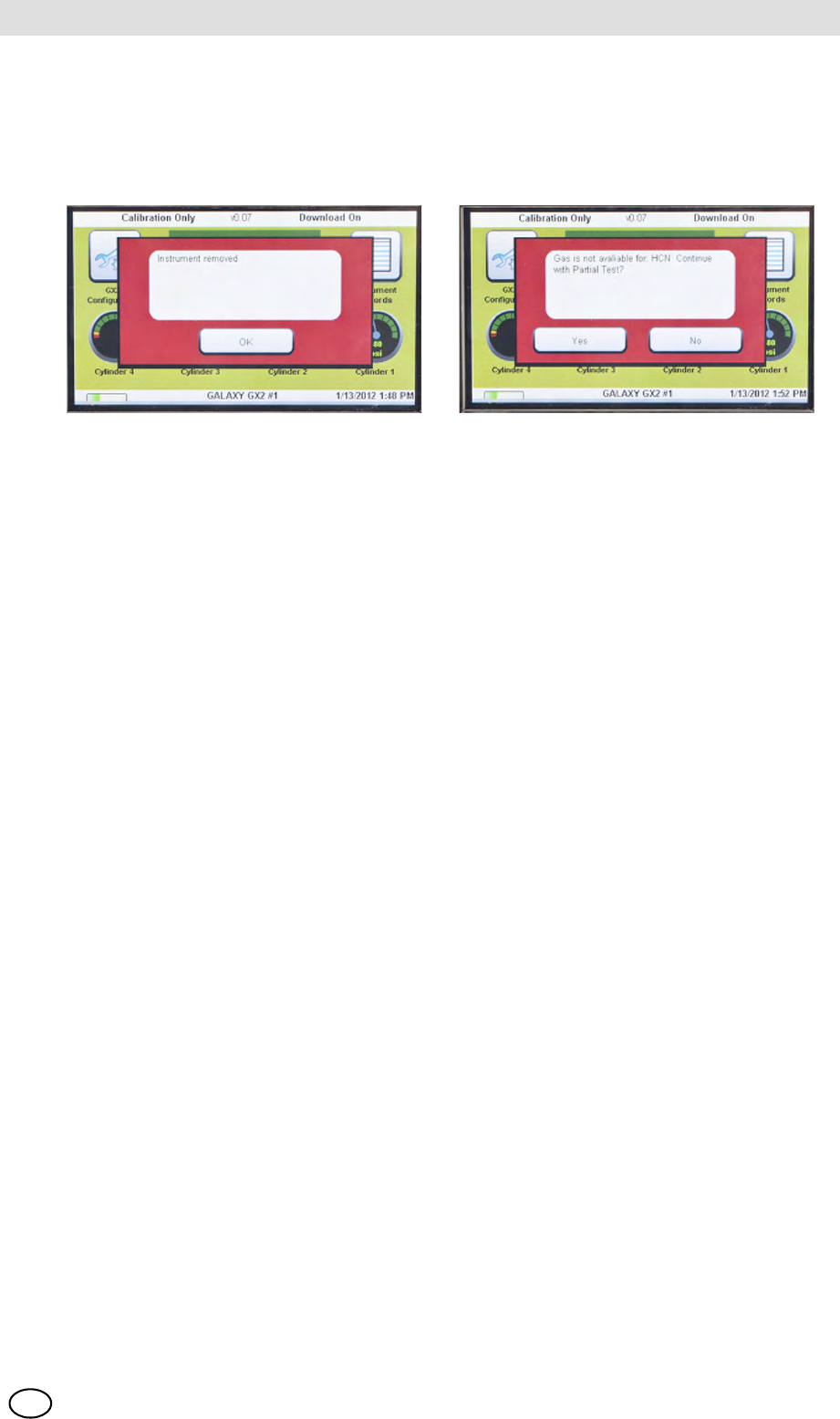
MSA AUER
MSA
Troubleshooting
GALAXY GX2 61
US
6.7 System Error Messages
The GALAXY GX2 can display a number of system errors that display on the Test Stand screen
with a red error box. The error message must be acknowledged for Test Stand operations to
resume.
Memory Card Write Protect
Occurs if the memory card cannot accept data. Ensure the switch on the side of the memory card
is unlocked so it can accept data.
Serial Number Required
Occurs when the instrument is missing its serial number. Use the free MSA Link software appli-
cation and an IR dongle to assign a serial number to the instrument. A unique non-zero serial
number is required for each gas detector model.
Pump Fault or Flow Fault
Occurs if pump(s) is blocked during a test, the test cylinder(s) read empty, the fresh air filter is
clogged, or an internal flow error occurs. Visually inspect the air filter for contamination and re-
place as needed. Refer to the Instrument Will Not Initiate a Bump or Calibration section
[ chapter 6.1] of this manual.
Partial Test
The test system lacks gases for a full test. Ensure the cylinder(s) configuration is set up correctly
and that adequate gas is present in the cylinder(s). Refer to Cylinder Configuration section
[ chapter 4.7] of this manual.
USB Drive Failure
Occurs if the user's flash drive cannot accept data. Ensure the flash drive is functioning properly.
If the USB Drive is full, delete unneeded data or replace with a new USB Drive. Check the USB
Drive Enable setting in the GALAXY GX2 Setup section [ chapter 4] of this manual.
Network Connection Lost
Occurs if the optional network set up malfunctions. Ensure the Ethernet cables are secure
between Test Stands, from the master unit to the PC, and that they are type 10/100 Mbps. Addi-
tional information on network connections can be found in the software product end-user manual.
GALAXY GX2
62
Maintenance (Cleaning and Part Replacement) MSA
US
7 Maintenance (Cleaning and Part Replacement)
7.1 Corrective Maintenance
See the listing below for common replacement parts associated with the GALAXY GX2. If you
have any questions regarding the equipment, any procedure in this manual, or the location of the
nearest MSA Repair Center and source of replacement parts, please call MSA Customer Service.
7.2 Replacement Parts and Accessories
WARNING
Repair or alteration of the GALAXY GX2 System beyond the scope of these instructions by an-
yone other than personnel authorized by MSA can endanger persons who rely on this equipment
for their safety or health and may void all warranties and approvals. Use only genuine MSA re-
placement parts.
Corrective Maintenance Items Part No.
AC Power supply, Global 10124286
Fresh Air Filter 10050789
Fresh Air Filter, High Capacity 10062363
Spare Parts Kit (feet, barb fittings, plugs) 10127020
Electronic Cylinder Holder 10105756
Non-electronic Cylinder Holder 10125135
Inlet Seal Replacement Kit (ALTAIR 5 Instrument) 10094844
ALTAIR Seal 10125136
ALTAIR Pro Seal 10125137
Zero Air Cylinder 801050
Screen protector 10125289
MSA AUER
MSA
Maintenance (Cleaning and Part Replacement)
GALAXY GX2 63
US
Accessories Part No.
4GB SD Card 10127111
MSA Link Pro Key (red) 10123938
Digital Secure USB Key (black) 10123937
End Cap 10113442
ALTAIR 4/4X Multi-Unit Charger 10105727
ALTAIR 5/5X Multi-Unit Charger 10105728
Sticker or Receipt/ Sticker Printer 10127808
Printer Cable 10127807
Instrument Sticker Label Roll (xx labels/ roll) 10126437
Receipt & Sticker Label Roll (xx labels/ roll) 10126438
Laminated Quick Start Guide xxxxxxxx
12" (TBR) Ethernet cable for Test Stand to Test Stand connection 10127518
DIN rail clip kit (2 clips & screws per kit) 10126657
Type Omega DIN Rail 0.5m, perforated, steel, zinc plated 10062364
Type Omega DIN Rail 1m, perforated, steel, zinc plated 10062365
Type Omega DIN Rail 2m, perforated, steel, zinc plated 10062366
USB IR Dongle (for use with MSA Link) 10082834
Demand Regulator 10034391
Large Capacity (<3000psi) Demand Regulator 710289
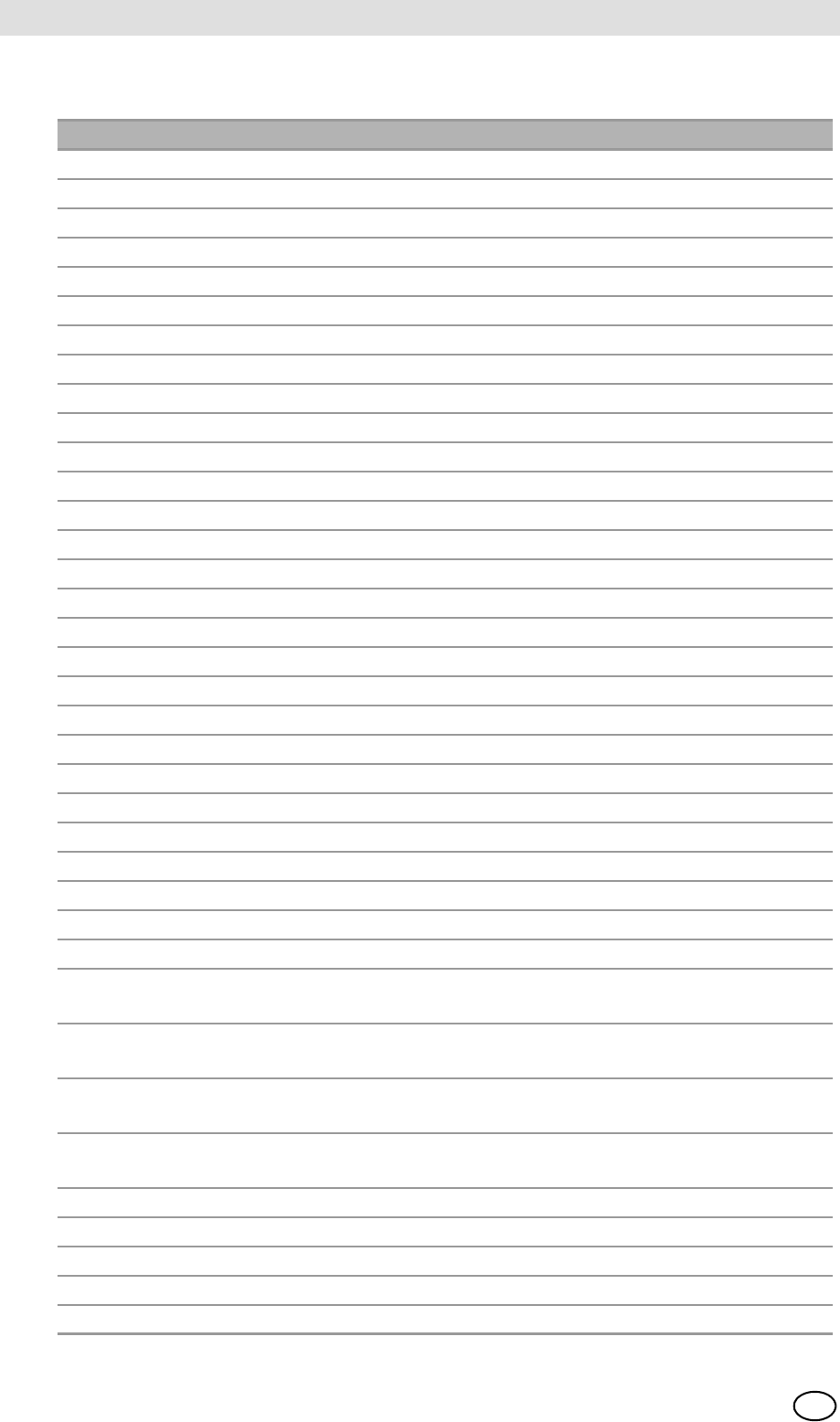
GALAXY GX2
64
Maintenance (Cleaning and Part Replacement) MSA
US
GALAXY CALIBRATION CYLINDERS
Type Gas Content Size PN
Quad 1.45% Methane, 15.0% O2, 60ppm CO, 20ppm H2S ECONO-CAL 10048280
Quad 1.45% Methane, 15.0% O2, 60ppm CO, 20ppm H2S RP CYLINDER 10045035
Quad 2.5% Methane, 15.0% O2, 60ppm CO, 20ppm H2S ECONO-CAL 10048981
Quad 2.5% Methane, 15.0% O2, 60ppm CO, 20ppm H2S RP CYLINDER 10048890
3-GAS 2.5% Methane, 15.0% O2, 20ppm H2S ECONO-CAL 10048888
3-GAS 2.5% Methane, 15.0% O2, 20ppm H2S RP CYLINDER 10048889
3 + NO21.45% Methane, 15.0% O2, 60ppm CO, 10 ppm NO2ECONO-CAL 10058036
3 + NO21.45% Methane, 15.0% O2, 60ppm CO, 10 ppm NO2RP CYLINDER 10058034
3 + NO22.5% Methane, 15.0% O2, 60ppm CO, 10 ppm NO2ECONO-CAL 10058172
3 + NO22.5% Methane, 15.0% O2, 60ppm CO, 10 ppm NO2RP CYLINDER 10058171
NO210 ppm ECONO-CAL 711068
NO210 ppm RP CYLINDER 808977
SO210 ppm ECONO-CAL 711070
SO210 ppm RP CYLINDER 808978
NH325 ppm ECONO-CAL 711078
NH325 ppm RP CYLINDER 814866
CL210 ppm ECONO-CAL 711066
CL210 ppm RP CYLINDER 806740
CL22 ppm ECONO-CAL 711082
CL22 ppm RP CYLINDER 10028080
HCN 10 ppm ECONO-CAL 711072
HCN 10 ppm RP CYLINDER 809351
PH30.5 ppm ECONO-CAL 711088
PH30.5 ppm RP CYLINDER 710533
CO 60 ppm 100L 710882
H2S 40 ppm ECONO-CAL 711062
H2S 40 ppm RP CYLINDER 467897
O220.80% 100L 479857
QD-CO21.45% Methane, 15.0% O2, 60ppm CO, 20ppm H2S,
2.5% CO2
RP CYLINDER 10103262
QUAD SO21.45% Methane, 15.0% O2, 60ppm CO, 20ppm H2S,
10ppm SO2
ECONO-CAL 10098855
QUAD SO21.45% Methane, 15.0% O2, 60ppm CO, 20ppm H2S,
10ppm SO2
RP CYLINDER 10117738
Air Zero
THC<1ppm
100L 801050
NO 50 ppm RP CYLINDER 812144
NO 50 ppm ECONO-CAL 711074
CH40.625% Methane, 15.0% O2, 60ppm CO RP CYLINDER 10125948
C5H12 0.375% Methane, 15.0% O2, 60ppm CO RP CYLINDER 10125947
CH40.625% Methane, 15.0% O2, 60ppm CO, 20ppm H2S RP CYLINDER 10125695

MSA AUER
MSA
Maintenance (Cleaning and Part Replacement)
GALAXY GX2 65
US
C5H12 0.375% Methane, 15.0% O2, 60ppm CO, 20ppm H2S RP CYLINDER 10125708
NO 50 PPM IN N2ECONO-CAL 10126429
Type Gas Content Size PN
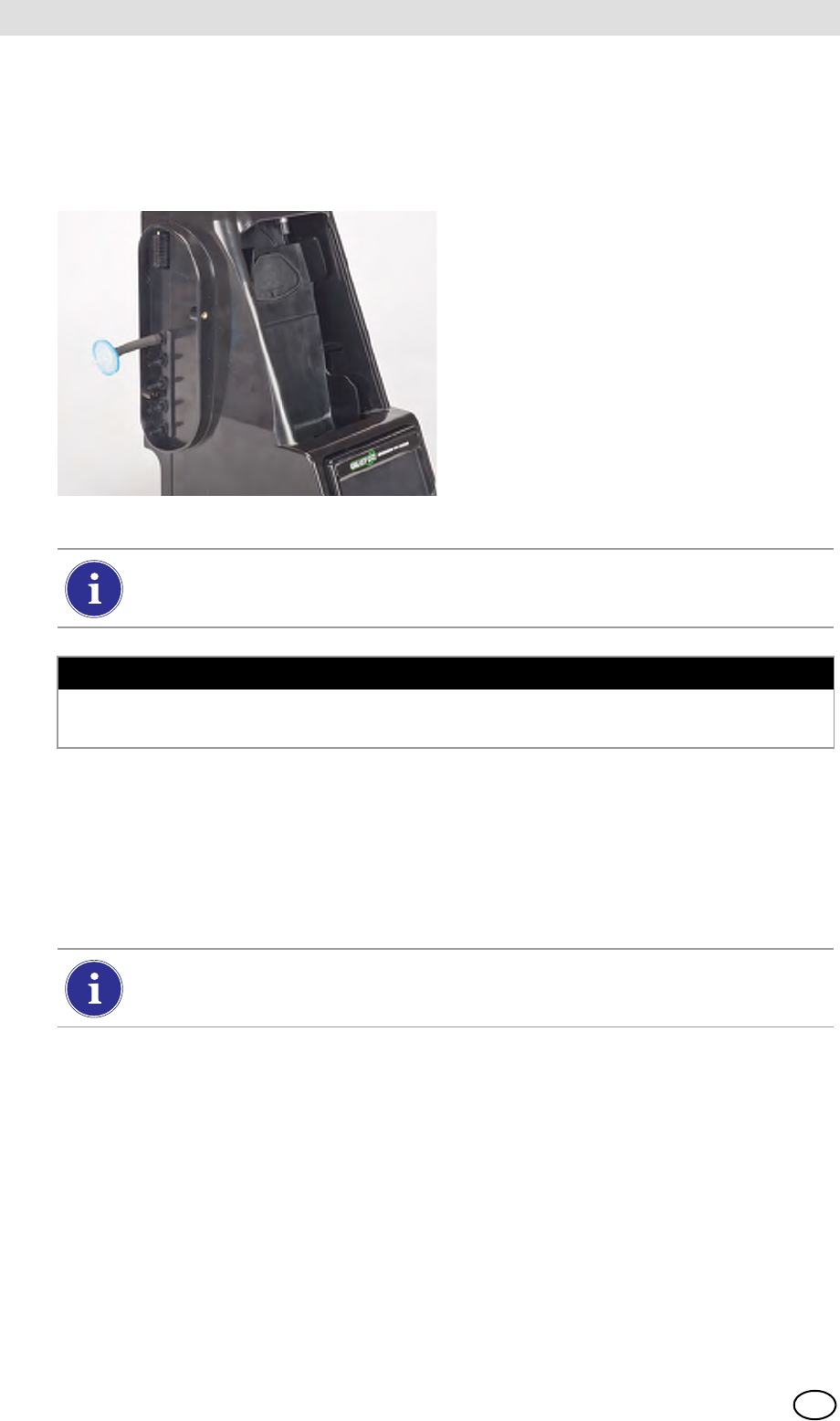
GALAXY GX2
66
Maintenance (Cleaning and Part Replacement) MSA
US
7.3 Fresh Air Filter Replacement
The disposable fresh air filter is located on the tubing attached to the upper port on the left side of
the farthest left unit. The filter requires periodic replacement, based on the unit's frequency of use
and environmental cleanliness. Visual inspection of the fresh air filter will indicate contamination.
Replace as needed.
Fig. 25 Fresh air filter
To Replace the Filter:
(1) Remove the filter and tubing from the barb fitting in the fresh air port on the left side of the
farthest left unit.
(2) Dispose of the old filter.
(3) Insert the new filter and tube onto the same barb fitting of the fresh air port.
Pump Alarms may indicate the need to replace the fresh air filter.
NOTICE
Do not run the unit without the filter in place (even if using a zero-air cylinder in your installation);
otherwise, the valves and pumps may be damaged.
If the system consists of four or more Test Stands, use the high capacity filter and
ensure the flow arrow indicator points toward the unit.
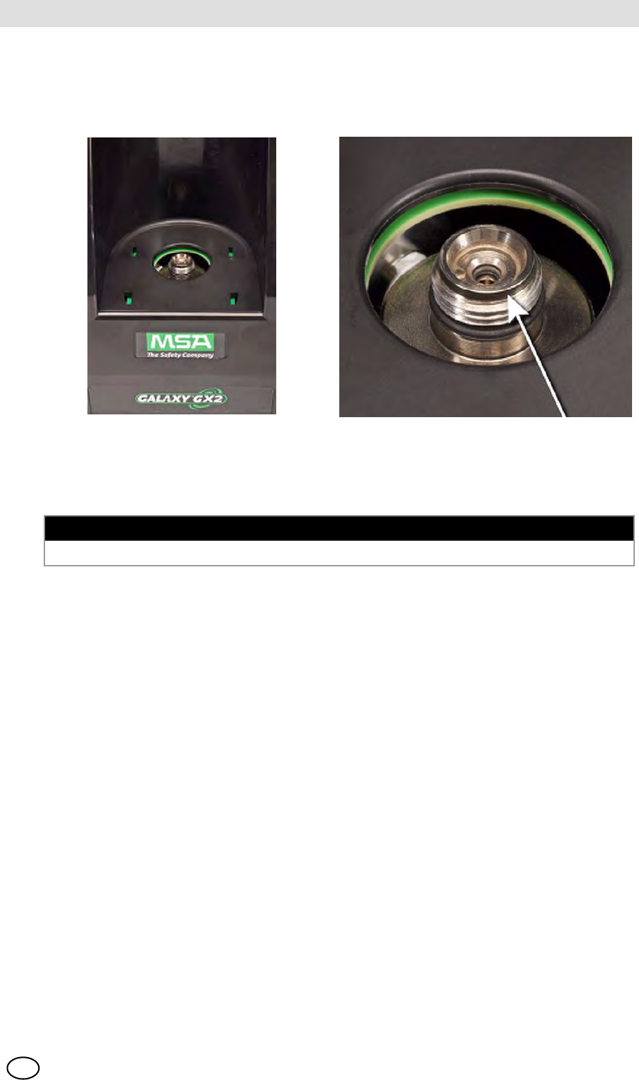
MSA AUER
MSA
Maintenance (Cleaning and Part Replacement)
GALAXY GX2 67
US
7.4 O-Ring Seal Replacement (Cylinder Holder)
Each month, visually inspect the O-ring on the fitting and clean if necessary. Replace if any dam-
age is found.
(1) Remove the damaged O-ring.
(2) Clean the fitting with a water-dampened cloth and apply a light film of mineral oil to the new
O-ring.
(3) Place the new O-ring onto the fitting.
7.5 Inlet Seal Replacement (ALTAIR 5/5X Gas Detector)
Flow Errors and Calibration Failures may indicate a damaged inlet seal. MSA recommends annual
seal replacement.
Replace the seal:
(1) Remove the stainless steel eyelet (collar).
(2) The rubber inlet seal can now be removed from the fitting.
(3) Place the wider (flared) end of a new inlet seal over the fitting.
(4) Replace the stainless steel eyelet (collar) and ensure it is seated at the top.
NOTICE
Do not use a silicone-based lubricant on this O-ring.
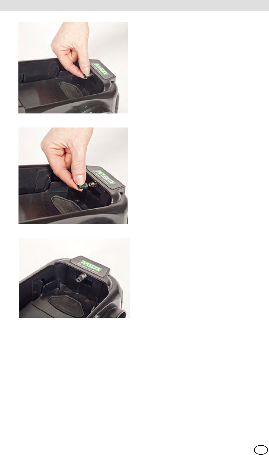
GALAXY GX2
68
Maintenance (Cleaning and Part Replacement) MSA
US
Fig. 26
Fig. 27
Fig. 28
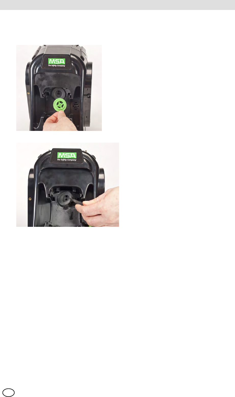
MSA AUER
MSA
Maintenance (Cleaning and Part Replacement)
GALAXY GX2 69
US
7.6 Rubber Insert Replacement (ALTAIR Gas Detector)
The rubber inserts may degrade in the GALAXY GX2 over time. Pull the degraded insert from the
Test Stand. Replace the insert and ensure that it is firmly seated.
Fig. 29
Fig. 30
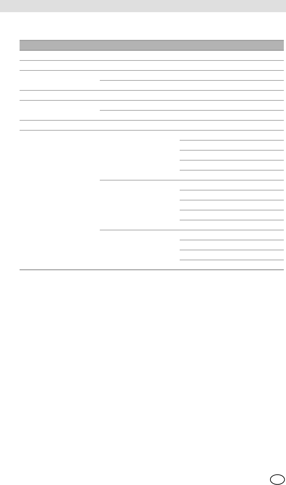
GALAXY GX2
70
Technical Specifications MSA
US
8 Technical Specifications
Specification Part Range
Operating Temperature GALAXY GX2 0-40º C
Power Input Power Module 100 - 240 VAC, 47 - 63 Hz
Optional Vehicle Module 9-32 VDC
Power Consumption Test Stand only < 6.0 W
With Cylinder Holder
Physical Characteristics Test Stand Height: 11.80" (299.72 mm)
Width: 6.50" (165.10 mm)
Depth: 7.90" (200.66 mm)
Material: Acrylonitrile Butadiene ABS
Cylinder Holder Height: 11.80" (299.72 mm)
Width: 6.50" (165.10 mm)
Depth: 6.10" (154.94 mm)
Material: Acrylonitrile Butadiene ABS
Multi-Unit Charger Height: 11.80" (299.72 mm)
Width: 6.50" (165.10 mm)
Depth: 6.44" (163.58 mm)
Material: Acrylonitrile Butadiene ABS
MSA AUER
MSA
Galaxy GX2 Default Parameters
GALAXY GX2 71
US
9 Galaxy GX2 Default Parameters
Refer to the listing below for the default settings for each display screen for configuring the
GALAXY GX2. The settings can be changed for optimal performance in the user's facility.
Screen Name Parameter Default Setting
Date Setup Date Current date set during assembly
Time Zone Setup Time Zone Eastern Time (US_ Canada)
Time Setup Time Current time set during assembly
24 Hour Time off
Test Setup Allow Simulant Gas yes for all
%volume to 100%LEL US setting for all
Test Setup - Mode Bump Only off
Calibration Only off
Bump/Cal on Fail on
Classic Mode off
Test Setup - Calibration Calibration Interval (days) 30
Test Setup - Bump Bump Interval (days) 1
Security Setup Passcode 0000 (off)
GX2 Setup - GX2 USB Drive Enable on
Display PSI on
Display bar off
GX2 Setup - Datalog Download Periodic off
Download Session off
Erase After Download off
GX2 Setup - Printing Print Calibration Sticker off
Print Receipt off
Volume Setup Volume Medium
Backlight Setup Intensity Very High
USB Drive Enabled On
Language Setup Language English
Cylinder Setup 1-4 Auto Cylinder Enable all on
Expiration Setup 1-4 Weeks to Expiration 4 weeks
LEL Setup %volume setting All combustible gas 100%LEL volumes
set to ANSI standards

MSA in Europe
[ www.msa-europe.com & www.msa-gasdetection.com ]
Northern Europe Southern Europe Eastern Europe Central Europe
Netherlands
MSA Nederland
Kernweg 20
1627 LH Hoorn
Phone +31 [229] 25 03 03
Fax +31 [229] 21 13 40
info@msaned.nl
Belgium
MSA Belgium
Duwijckstraat 17
2500 Lier
Phone +32 [3] 491 91 50
Fax +32 [3] 491 91 51
msabelgium@msa.be
Great Britain
MSA Britain
Lochard House
Linnet Way
Strathclyde Business Park
BELLSHILL ML4 3RA
Scotland
Phone +44 [16 98] 57 33 57
Fax +44 [16 98] 74 0141
info@msabritain.co.uk
Sweden
MSA NORDIC
Kopparbergsgatan 29
214 44 Malmö
Phone +46 [40] 699 07 70
Fax +46 [40] 699 07 77
info@msanordic.se
MSA SORDIN
Rörläggarvägen 8
33153 Värnamo
Phone +46 [370] 69 35 50
Fax +46 [370] 69 35 55
info@sordin.se
France
MSA GALLET
Zone Industrielle Sud
01400 Châtillon sur
Chalaronne
Phone +33 [474] 55 01 55
Fax +33 [474] 55 47 99
message@msa-gallet.fr
Italy
MSA Italiana
Via Po 13/17
20089 Rozzano [MI]
Phone +39 [02] 89 217 1
Fax +39 [02] 82 59 228
info-italy@
msa-europe.com
Spain
MSA Española
Narcís Monturiol, 7
Pol. Ind. del Sudoeste
08960 Sant-Just Desvern
[Barcelona]
Phone +34 [93] 372 51 62
Fax +34 [93] 372 66 57
info@msa.es
Poland
MSA Safety Poland
ul. Wschodnia 5A
05-090 Raszyn k/Warszawy
Phone +48 [22] 711 50 33
Fax +48 [22] 711 50 19
eer@msa-europe.com
Czech Republic
MSA Safety Czech
Pikartská 1337/7
716 07 Ostrava-Radvanice
Phone +420 [59] 6 232222
Fax +420 [59] 6 232675
info@msa-auer.cz
Hungary
MSA Safety Hungaria
Francia út 10
1143 Budapest
Phone +36 [1] 251 34 88
Fax +36 [1] 251 46 51
info@msa.hu
Romania
MSA Safety Romania
Str. Virgil Madgearu, Nr. 5
Ap. 2, Sector 1
014135 Bucuresti
Phone +40 [21] 232 62 45
Fax +40 [21] 232 87 23
office@msanet.ro
Russia
MSA Safety Russia
Pokhodny Proezd, 14
125373 Moscow
Phone +7 [495] 921 1370/74
Fax +7 [495] 921 1368
msa-moscow@
msa-europe.com
Germany
MSA AUER GmbH
Thiemannstrasse 1
12059 Berlin
Phone +49 [30] 68 86 0
Fax +49 [30] 68 86 15 17
info@msa-auer.de
Austria
MSA AUER Austria
Vertriebs GmbH
Modecenterstrasse 22
MGC Office 4, Top 601
A-1030 Wien
Phone +43 [0] 1 / 796 04 96
Fax +43 [0] 1 / 796 04 96 - 20
info@msa-auer.at
Switzerland
MSA Schweiz
Eichweg 6
8154 Oberglatt
Phone +41 [43] 255 89 00
Fax +41 [43] 255 99 90
info@msa.ch
European
International Sales
[Africa, Asia, Australia, Latin
America, Middle East]
MSA EUROPE
Thiemannstrasse 1
12059 Berlin
Phone +49 [30] 68 86 0
Fax +49 [30] 68 86 15 58
contact@msa-europe.com